

Kenwood 3750-X, 3560-X Hardware Installation Manual

Catalyst 3750-X and 3560-X Switch
Hardware Installation Guide
June 2011
Revised: April 2013
Americas Headquarters
Cisco Systems, Inc.
170 West Tasman Drive
San Jose, CA 95134-1706
USA
http://www.cisco.com
Tel: 408 526-4000
800 553-NETS (6387)
Fax: 408 527-0883
Text Part Number: OL-19593-03

THE SPECIFICATIONS AND INFORMATION REGARDING THE PRODUCTS IN THIS MANUAL ARE SUBJECT TO CHANGE WITHOUT NOTICE. ALL
STATEMENTS, INFORMATION, AND RECOMMENDATIONS IN THIS MANUAL ARE BELIEVED TO BE ACCURATE BUT ARE PRESENTED WITHOUT
WARRANTY OF ANY KIND, EXPRESS OR IMPLIED. USERS MUST TAKE FULL RESPONSIBILITY FOR THEIR APPLICATION OF ANY PRODUCTS.
THE SOFTWARE LICENSE AND LIMITED WARRANTY FOR THE ACCOMPANYING PRODUCT ARE SET FORTH IN THE INFORMATION PACKET THAT
SHIPPED WITH THE PRODUCT AND ARE INCORPORATED HEREIN BY THIS REFERENCE. IF YOU ARE UNABLE TO LOCATE THE SOFTWARE LICENSE
OR LIMITED WARRANTY, CONTACT YOUR CISCO REPRESENTATIVE FOR A COPY.
The following inform ation is for FCC compliance of Class A devices: This equipment has been tested and found to comply with the limits for a Class A digital device, pursuant
to part 15 of the FCC rules. These limits are designed to provide reasonable protection against harmful interference when the equipment is operated in a commercial
environment. This equipment generates, uses, and can radiate radio-frequency energy and, if not installed and used in accordance with the instruction manual, may cause
harmful interference to radio communications. Operation of this equipment in a residential area is likely to cause harmful interference, in which case users will be required
to correct the interference at their own expense.
The following information is for FCC compliance of Class B devices: The equipment described in this manual generates and may radiate radio-frequency energy. If it is not
installed in accordance with Cisco’s installation instructions, it may cause interference with radio and television reception. This equipment has been tested and found to
comply with the limits for a Class B digital device in accordance with the specifications in part 15 of the FCC rules. These specifications are designed to provide reasonable
protection against such interference in a residential installation. However, there is no guarantee that interference will not occur in a particular installation.
Modifying the equipment without Cisco’s written authorization may result in the equipment no longer complying with FCC requirements for Class A or Class B digital
devices. In that event, your right to use the equipment may be limited by FCC regulations, and you may be required to correct any interference to radio or television
communications at your own expense.
You can determine whether your equipment is causing interference by turning it off. If the interference stops, it was probably caused by the Cisco equipment or one of its
peripheral devices. If the equipment causes interference to radio or television reception, try to correct the interference by using one or more of the following measures:
• Turn the television or radio antenna until the interference stops.
• Move the equipment to one side or the other of the television or radio.
• Move the equipment farther away from the television or radio.
• Plug the equipment into an outlet that is on a different circuit from the television or radio. (That is, make certain the equipment and the television or radio are on circuits
controlled by different circuit breakers or fuses.)
Modifications to this product not authorized by Cisco Systems, Inc. could void the FCC approval and negate your authority to operate the product.
The Cisco implementation of TCP header compression is an adaptation of a program developed by the University of California, Berkeley (UCB) as part of UCB’s public
domain version of the UNIX operating system. All rights reserved. Copyright © 1981, Regents of the University of California.
NOTWITHSTANDING ANY OTHER WARRANTY HEREIN, ALL DOCUMENT FILES AND SOFTWARE OF THESE SUPPLIERS ARE PROVIDED “AS IS” WITH
ALL FAULTS. CISCO AND THE ABOVE-NAMED SUPPLIERS DISCLAIM ALL WARRANTIES, EXPRESSED OR IMPLIED, INCLUDING, WITHOUT
LIMITATION, THOSE OF MERCHANTABILITY, FITNESS FOR A PARTICULAR PURPOSE AND NONINFRINGEMENT OR ARISING FROM A COURSE OF
DEALING, USAGE, OR TRADE PRACTICE.
IN NO EVENT SHALL CISCO OR ITS SUPPLIERS BE LIABLE FOR ANY INDIRECT, SPECIAL, CONSEQUENTIAL, OR INCIDENTAL DAMAGES, INCLUDING,
WITHOUT LIMITATION, LOST PROFITS OR LOSS OR DAMAGE TO DATA ARISING OUT OF THE USE OR INABILITY TO USE THIS MANUAL, EVEN IF CISCO
OR ITS SUPPLIERS HAVE BEEN ADVISED OF THE POSSIBILITY OF SUCH DAMAGES.
Cisco and the Cisco logo are trademarks or registered trademarks of Cisco and/or its affiliates in the U.S. and other countries. To view a list of Cisco trademarks, go to this
URL: www.cisco.com/go/trademarks. Third-party trademarks mentioned are the property of their respective owners. The use of the word partner does not imply a partnership
relationship between Cisco and any other company. (1110R)
Catalyst 3750-X and 3560-X Switch Hardware Installation Guide
© 2010–2013 Cisco Systems, Inc. All rights reserved.

CONTENTS
CHAPTER
Preface
1
Product Overview
vii
1-1
Switch Models
Front Panel Description
SFP Module Slots
10/100/1000 Ethernet Ports
PoE+ and UPOE Ports
Network Modules
LEDs
USB Mini-Type B Port
Rear Panel Description
RJ-45 Console Port LED
USB Type A Interface
StackWise Ports
Power Supply Modules
Fan Modules
XPS Connector
1-1
1-5
1-6
1-6
1-6
1-7
1-11
1-18
1-18
1-19
1-19
1-20
1-20
1-23
1-23
StackPower Connector (Catalyst 3750-X Switches)
Management Ports
1-24
1-24
Management Options
Network Configurations
CHAPTER
2
Switch Installation
Preparing for Installation
Safety Warnings
Installation Guidelines
Tools and Equipment
Planning a Switch Data Stack (Catalyst 3750-X Switches)
Switch Data Stacking Guidelines
Data Stack Cabling Configurations
Data Stack Bandwidth and Partitioning Examples
Power On Sequence for Switch Data Stacks
OL-19593-03
1-25
1-26
2-1
2-1
2-1
2-4
2-5
2-5
2-5
2-6
2-7
2-8
Catalyst 3750-X and 3560-X Switch Hardware Installation Guide
iii

Contents
Planning a StackPower Stack (Catalyst 3750-X Switches)
StackPower Stacking Guidelines
StackPower Cabling Configurations
StackPower Partitioning Examples
Installing the Switch
Rack-Mounting
2-15
2-15
Table- or Shelf-Mounting
After Installing the Switch
2-9
2-10
2-14
2-19
2-19
2-9
Connecting to the StackWise Ports (Catalyst 3750-X Switches)
Connecting to the StackPower Ports (Catalyst 3750-X Switches)
Connecting the StackPower Ports to the XPS 2200
Installing a Network Module in the Switch
Tools and Equipment
Installing Network Modules
Removing a Network Module
Installing SFP and SFP+ Modules
Installing an SFP Module
Removing an SFP Module
2-23
2-23
2-24
2-24
2-25
2-26
2-22
2-22
2-19
2-20
CHAPTER
Connecting Devices to the Ethernet Ports
10/100/1000 Ethernet Port Connections
PoE+ and UPOE Port Connections
Where to Go Next
3
Power Supply and Fan Module Installation
Power Supply Module Overview
Installation Guidelines
Installing an AC Power Supply
Installing a DC Power Supply
Equipment That You Need
Grounding the Switch
2-29
3-1
3-5
3-7
3-8
3-8
3-9
Installing the DC Power Supply in the Switch
Wiring the DC Input Power Source
Finding the Power Supply Module Serial Number
Fan Module Overview
Installing a Fan Module
3-14
3-15
2-26
2-27
2-27
3-1
3-11
3-11
3-12
Finding the Fan Module Serial Number
Catalyst 3750-X and 3560-X Switch Hardware Installation Guide
iv
3-15
OL-19593-03

Contents
CHAPTER
APPENDIX
APPENDIX
4
A
B
Troubleshooting
Diagnosing Problems
Switch POST Results
Switch LEDs
Switch Connections
Switch Performance
Resetting the Switch to the Factory Default Settings
Finding the Switch Serial Number
4-1
4-1
4-1
4-1
4-2
4-4
4-5
4-6
Replacing a Failed Data Stack Member (Catalyst 3750-X Switches)
Technical Specifications
Switch Specifications
Power Supply Module Specifications
Fan Module Specifications
Connector and Cable Specifications
Connector Specifications
10/100/1000 Ports
A-1
A-1
A-2
A-4
B-1
B-1
B-1
10 Gigabit Ethernet CX1 (SFP+ Copper) Connectors
SFP and SFP+ Modules
10/100 Ethernet Management Port
Console Port
B-4
B-2
B-3
4-6
B-2
APPENDIX
OL-19593-03
Cable and Adapter Specifications
SFP and SFP+ Module Cable Specifications
Four Twisted-Pair Cable Pinouts
Two Twisted-Pair Cable Pinouts
Identifying a Crossover Cable
Console Port Adapter Pinouts
C
Configuring the Switch with the CLI-Based Setup Program
Accessing the CLI
C-1
Accessing the CLI Through Express Setup
Accessing the CLI Through a Console Port
Installing the Cisco Microsoft Windows USB Device Driver
Uninstalling the Cisco Microsoft Windows USB Driver
Entering the Initial Configuration Information
IP Settings
C-6
Configuring the Setup Program
B-5
B-5
B-7
B-7
B-8
B-8
C-1
C-1
C-2
C-3
C-5
C-6
C-6
Catalyst 3750-X and 3560-X Switch Hardware Installation Guide
v

Contents
Catalyst 3750-X and 3560-X Switch Hardware Installation Guide
vi
OL-19593-03

Preface
Purpose
This guide describes the hardware features of the Catalyst 3750-X and 3560-X switches. It describes the
physical and performance characteristics of each switch, explains how to install a switch, and provides
troubleshooting information.
This guide does not describe system messages that you might receive or how to configure your switch.
See the switch software configuration guide, the switch command reference, and the switch system
message guide on
http://www.cisco.com/en/US/products/ps10745/tsd_products_support_series_home.html
Related Publications
Catalyst 3750-X switches:
http://www.cisco.com/en/US/products/ps10745/tsd_products_support_series_home.html
Catalyst 3560-X switches:
http://www.cisco.com/en/US/products/ps10744/tsd_products_support_series_home.html
OL-19593-03
•
Catalyst 3750-X and 3560-X Switch Getting Started Guide
•
Catalyst 3750-X and 3560-X Switch Hardware Installation Guide
•
Regulatory Compliance and Safety Information for the Catalyst 3750-X and 3560-X Switch
•
Installation Notes for the Catalyst 3750-X, Catalyst 3560-X Switch Power Supply Modules
•
Installation Notes for the Catalyst 3750-X and 3560-X Switch Fan Module
•
Installation Notes for the Catalyst 3750-X and 3560-X Switch Network Modules
•
Release Notes for the Catalyst 3750-X and 3560-X Switch
•
Catalyst 3750-X and 3560-X Switch Software Configuration Guide
•
Catalyst 3750-X and 3560-X Switch Command Reference
•
Catalyst 3750-X, 3750-E, 3560-X, and 3560-E Switch System Message Guide
•
Cisco IOS Software Installation Document
Catalyst 3750-X and 3560-X Switch Hardware Installation Guide
vii

Information about Cisco SFP and SFP+ modules is available from this Cisco.com site:
http://www.cisco.com/en/US/products/hw/modules/ps5455/prod_installation_guides_list.html
SFP compatibility matrix documents are available from this Cisco.com site:
http://www.cisco.com/en/US/products/hw/modules/ps5455/products_device_support_tables_list.html
Obtaining Documentation and Submitting a Service Request
For information on obtaining documentation, submitting a service request, and gathering additional
information, see the monthly What’s New in Cisco Product Documentation, which also lists all new and
revised Cisco technical documentation, at:
http://www.cisco.com/en/US/docs/general/whatsnew/whatsnew.html
Subscribe to the What’s New in Cisco Product Documentation as a Really Simple Syndication (RSS) feed
and set content to be delivered directly to your desktop using a reader application. The RSS feeds are a free
service and Cisco currently supports RSS Version 2.0.
Chapter
Catalyst 3750-X and 3560-X Switch Hardware Installation Guide
viii
OL-19593-03
CHA PTER
1
Product Overview
The Catalyst 3750-X and 3560-X series switches are Ethernet switches to which you can connect devices
such as Cisco IP Phones, Cisco Wireless Access Points, workstations, and other network devices such
as servers, routers, and other switches.
The Catalyst 3750-X switches support stacking through Cisco StackWise technology and power
management through Cisco StackPower technology. The Catalyst 3560-X switches do not support
switch stacking or StackPower.
Unless otherwise noted, the term switch refers to a standalone switch and to a switch stack.
•
Switch Models, page 1-1
•
Front Panel Description, page 1-5
•
Rear Panel Description, page 1-18
•
Management Options, page 1-25
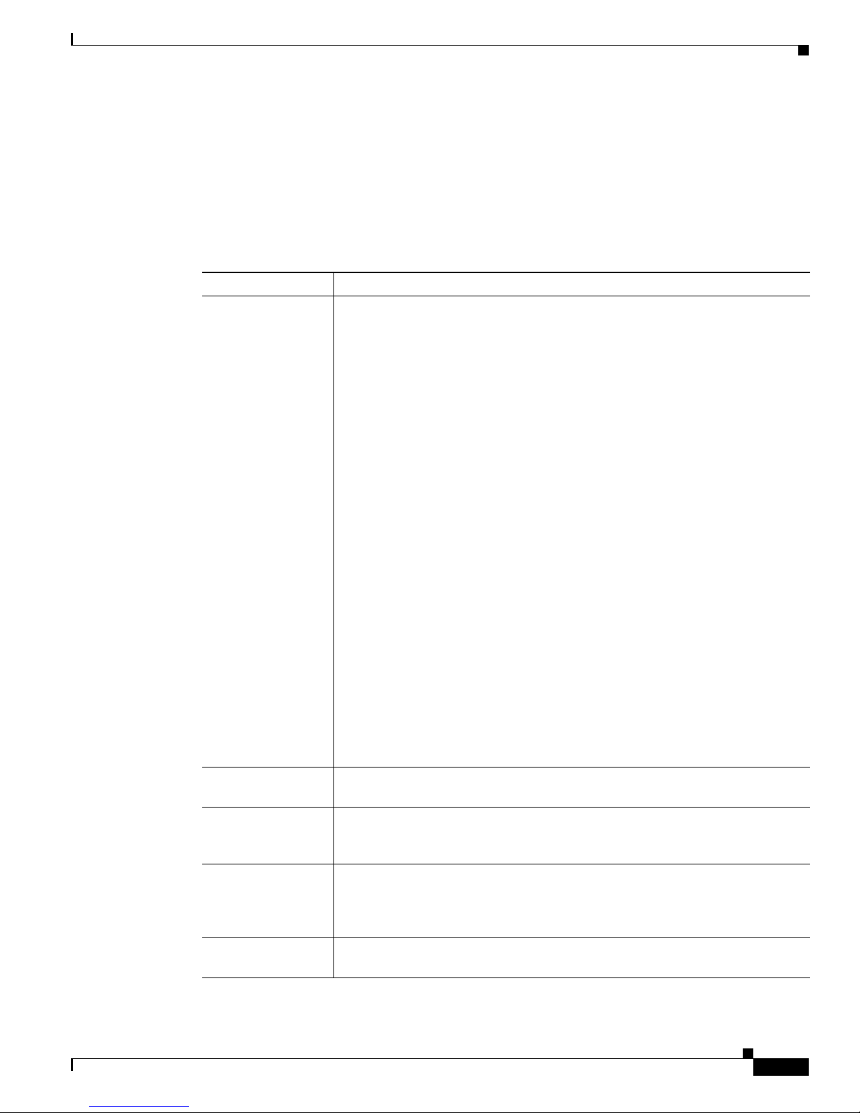
Switch Models
Table 1-1 Catalyst 3750-X Switch Models
Switch Model Cisco IOS Image Description
Catalyst 3750-X-24T-L LAN Base image 24 10/100/1000 Ethernet ports, StackWise Plus, 1
Catalyst 3750-X-48T-L LAN Base image 48 10/100/1000 Ethernet ports, StackWise Plus, one
Catalyst 3750-X-24P-L LAN Base image 24 10/100/1000 PoE+
Catalyst 3750-X-48P-L LAN Base image 48 10/100/1000 PoE+
Catalyst 3750-X-48PF-L LAN Base image 48 10/100/1000 PoE+
Catalyst 3750-X-24U-L
network module
network module
network module
network module
network module
3
LAN Base image 24 10/100/1000 UPOE4 ports, StackWise Plus,
StackPower, 1 network module
supply
1
slot, 350-W power supply
1
slot, 350-W power supply
2
ports, StackWise Plus, 1
1
slot, 715-W power supply
2
ports, StackWise Plus, one
1
slot, 715-W power supply
2
ports, StackWise Plus, 1
1
slot, 1100-W power supply
1
slot, 1100-W power
OL-19593-03
Catalyst 3750-X and 3560-X Switch Hardware Installation Guide
1-1

Switch Models
Chapter 1 Product Overview
Table 1-1 Catalyst 3750-X Switch Models (continued)
Switch Model Cisco IOS Image Description
Catalyst 3750-X-48U-L3LAN Base image 48 10/100/1000 UPOE4 ports, StackWise Plus,
StackPower, 1 network module
1
slot, 1100-W power
supply
Catalyst 3750-X-24T-S IP Base image 24 10/100/1000 Ethernet ports, StackWise Plus,
StackPower, 1 network module
1
slot, 350-W power
supply
Catalyst 3750-X-48T-S IP Base image 48 10/100/1000 Ethernet ports, StackWise Plus,
StackPower, 1 network module
1
slot, 350-W power
supply
Catalyst 3750-X-24P-S IP Base image 24 10/100/1000 PoE+
StackPower, 1 network module
2
ports, StackWise Plus,
1
slot, 715-W power
supply
Catalyst 3750-X-48P-S IP Base image 48 10/100/1000 PoE+
StackPower, 1 network module
2
ports, StackWise Plus,
1
slot, 715-W power
supply
Catalyst 3750-X-48PF-S IP Base image 48 10/100/1000 PoE+
StackPower, 1 network module
2
ports, StackWise Plus,
1
slot, 1100-W power
supply
3
Catalyst 3750-X-24U-S
IP Base image 24 10/100/1000 UPOE4 ports, StackWise Plus,
StackPower, 1 network module
1
slot, 1100-W power
supply
Catalyst 3750-X-48U-S
3
IP Base image 48 10/100/1000 UPOE4 ports, StackWise Plus,
StackPower, 1 network module
1
slot, 1100-W power
supply
Catalyst 3750-X-12S-S IP Base image 12 SFP module slots, StackWise Plus, StackPower,
1 network module
1
slot, 350-W power supply
Catalyst 3750-X-24S-S IP Base image 24 SFP module slots, StackWise Plus, StackPower,
1 network module
Catalyst 3750-X-24T-E IP Services image 24 10/100/1000 Ethernet ports, StackWise Plus,
StackPower, 1 network module
1
slot, 350-W power supply
1
slot, 350-W power
supply
Catalyst 3750-X-48T-E IP Services image 48 10/100/1000 Ethernet ports, StackWise Plus,
StackPower, 1 network module
1
slot, 350-W power
supply
2
Catalyst 3750-X-24P-E IP Services image 24 10/100/1000 PoE+
StackPower, 1 network module
ports, StackWise Plus,
1
slot, 715-W power
supply
Catalyst 3750-X-48P-E IP Services image 48 10/100/1000 PoE+
StackPower, 1 network module
2
ports, StackWise Plus,
1
slot, 715-W power
supply
2
Catalyst 3750-X-48PF-E IP Services image 48 10/100/1000 PoE+
StackPower, 1 network module
ports, StackWise Plus,
1
slot, 1100-W power
supply
Catalyst 3750-X and 3560-X Switch Hardware Installation Guide
1-2
OL-19593-03
Chapter 1 Product Overview
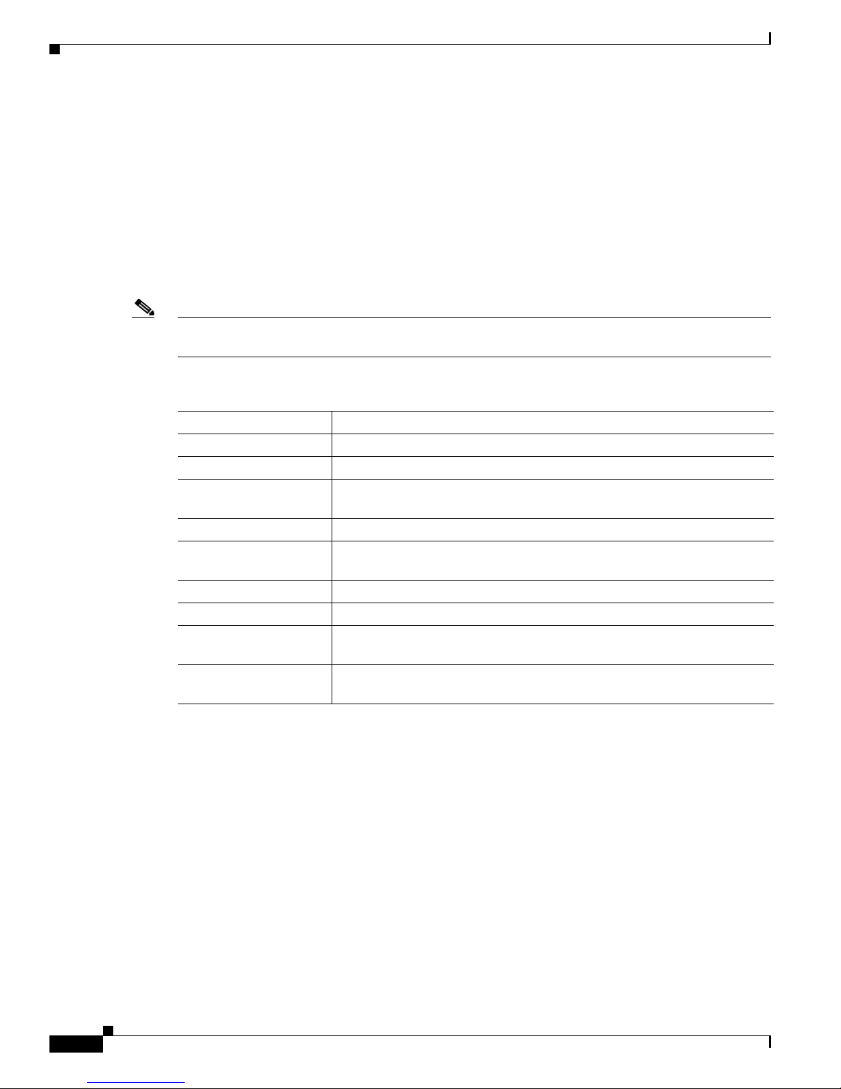
Table 1-1 Catalyst 3750-X Switch Models (continued)
Switch Model Cisco IOS Image Description
Catalyst 3750-X-24U-E3IP Services image 24 10/100/1000 UPOE4 ports, StackWise Plus,
Catalyst 3750-X-48U-E
Catalyst 3750-X-12S-E IP Services image 12 SFP module slots, StackWise Plus, StackPower,
Catalyst 3750-X-24S-E IP Services image 24 SFP module slots, StackWise Plus, StackPower,
1. Available network modules: 10-Gigabit Ethernet network module; 10-Gigabit Ethernet (copper) network module; 10-Gigabit
2. PoE+ = Power over Ethernet plus (provides up to 30 W per port).
3. Not supported for NEBS.
4. UPOE = Universal Power over Ethernet (provides up to 60 W per port).
StackPower, 1 network module
1
slot, 1100-W power
supply
3
IP Services image 48 10/100/1000 UPOE4 ports, StackWise Plus,
StackPower, 1 network module
1
slot, 1100-W power
supply
1 network module
1 network module
Ethernet service module; 1-Gigabit Ethernet network module; blank module (see Table 1-3 on page 1-7).
1
slot, 350-W power supply
1
slot, 350-W power supply
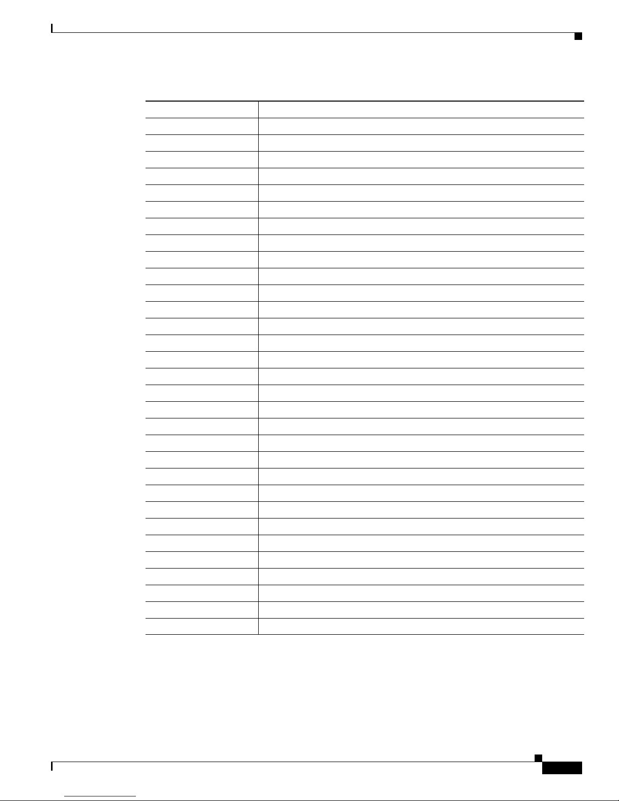
Switch Models
Table 1-2 Catalyst 3560-X Switch Models
Switch Part Number Description
Catalyst 3560-X-24T-L LAN Base image 24 10/100/1000 Ethernet ports, 1 network module
slot, 350-W power supply
Catalyst 3560-X-48T-L LAN Base image 48 10/100/1000 Ethernet ports, 1 network module
slot, 350-W power supply
Catalyst 3560-X-24P-L LAN Base image 24 10/100/1000 PoE+
2
ports, 1 network module1 slot,
715-W power supply
2
Catalyst 3560-X-48P-L LAN Base image 48 10/100/1000 PoE+
ports, 1 network module1 slot,
715-W power supply
Catalyst 3560-X-48PF-L LAN Base image 48 10/100/1000 PoE+
2
ports, 1 network module1 slot,
1100-W power supply
Catalyst 3560-X-24U-L
3
LAN Base image 24 10/100/1000 UPOE4 ports, 1 network module1 slot,
1100-W power supply
Catalyst 3560-X-48U-L
3
LAN Base image 48 10/100/1000 UPOE4 ports, 1 network module1 slot,
1100-W power supply
Catalyst 3560-X-24T-S IP Base image 24 10/100/1000 Ethernet ports, 1 network module
slot, 350-W power supply
Catalyst 3560-X-48T-S IP Base image 48 10/100/1000 Ethernet ports, 1 network module
slot, 350-W power supply
2
Catalyst 3560-X-24P-S IP Base image 24 10/100/1000 PoE+
ports, 1 network module1 slot,
715-W power supply
Catalyst 3560-X-48P-S IP Base image 48 10/100/1000 PoE+
2
ports, 1 network module1 slot,
715-W power supply
2
Catalyst 3560-X-48PF-S IP Base image 48 10/100/1000 PoE+
ports, 1 network module1 slot,
1100-W power supply
1
1
1
1
OL-19593-03
Catalyst 3750-X and 3560-X Switch Hardware Installation Guide
1-3
Switch Models
Chapter 1 Product Overview
Table 1-2 Catalyst 3560-X Switch Models (continued)
Switch Part Number Description
Catalyst 3560-X-24U-S3IP Base image 24 10/100/1000 UPOE4 ports, 1 network module1 slot,
1100-W power supply
Catalyst 3560-X-48U-S
3
IP Base image 48 10/100/1000 UPOE4 ports, 1 network module1 slot,
1100-W power supply
1
Catalyst 3560-X-24T-E IP Services image 24 10/100/1000 Ethernet ports, 1 network module
slot, 350-W power supply
Catalyst 3560-X-48T-E IP Services image 48 10/100/1000 Ethernet ports, 1 network module
1
slot, 350-W power supply
2
Catalyst 3560-X-24P-E IP Services image 24 10/100/1000 PoE+
ports, 1 network module1 slot,
715-W power supply
Catalyst 3560-X-48P-E IP Services image 48 10/100/1000 PoE+
2
ports, 1 network module1 slot,
715-W power supply
Catalyst 3560-X-48PF-E IP Services image 48 10/100/1000 PoE+
2
ports, 1 network module1 slot,
1100-W power supply
Catalyst 3560-X-24U-E
3
IP Services image 24 10/100/1000 UPOE4 ports, 1 network module1 slot,
1100-W power supply
3
Catalyst 3560-X-48U-E
IP Services image 48 10/100/1000 UPOE4 ports, 1 network module1 slot,
1100-W power supply
1. Available network modules: 10-Gigabit Ethernet network module; 10-Gigabit Ethernet (copper) network module; 10-Gigabit
Ethernet service module; 1-Gigabit Ethernet network module; blank module (see Table 1-3 on page 1-7).
2. PoE+ = Power over Ethernet plus (provides up to 30 W per port).
3. Not supported for NEBS.
4. UPOE = Universal Power over Ethernet (provides up to 60 W per port).
Catalyst 3750-X and 3560-X Switch Hardware Installation Guide
1-4
OL-19593-03
Chapter 1 Product Overview
251960
Catalyst 3750-X PoE+48
SYST
XPS
STAT
SPEED
DUPLX
EN
PoE
STACK
MAST
S-PWR
MODE
CONSOLE
1
2
3
4
5
6
7
8
9
10
11
12
13
14
15
16
17
18
19
20
21
22
23
24
25
26
27
28
29
30
31
32
33
34
35
36
37
38
39
40
41
42
43
44
45
46
47
48
1
2
3
4
5
C3KX-NM-10G
NETWORK
MODULE
G1
G2/TE1
G3
G4/TE2
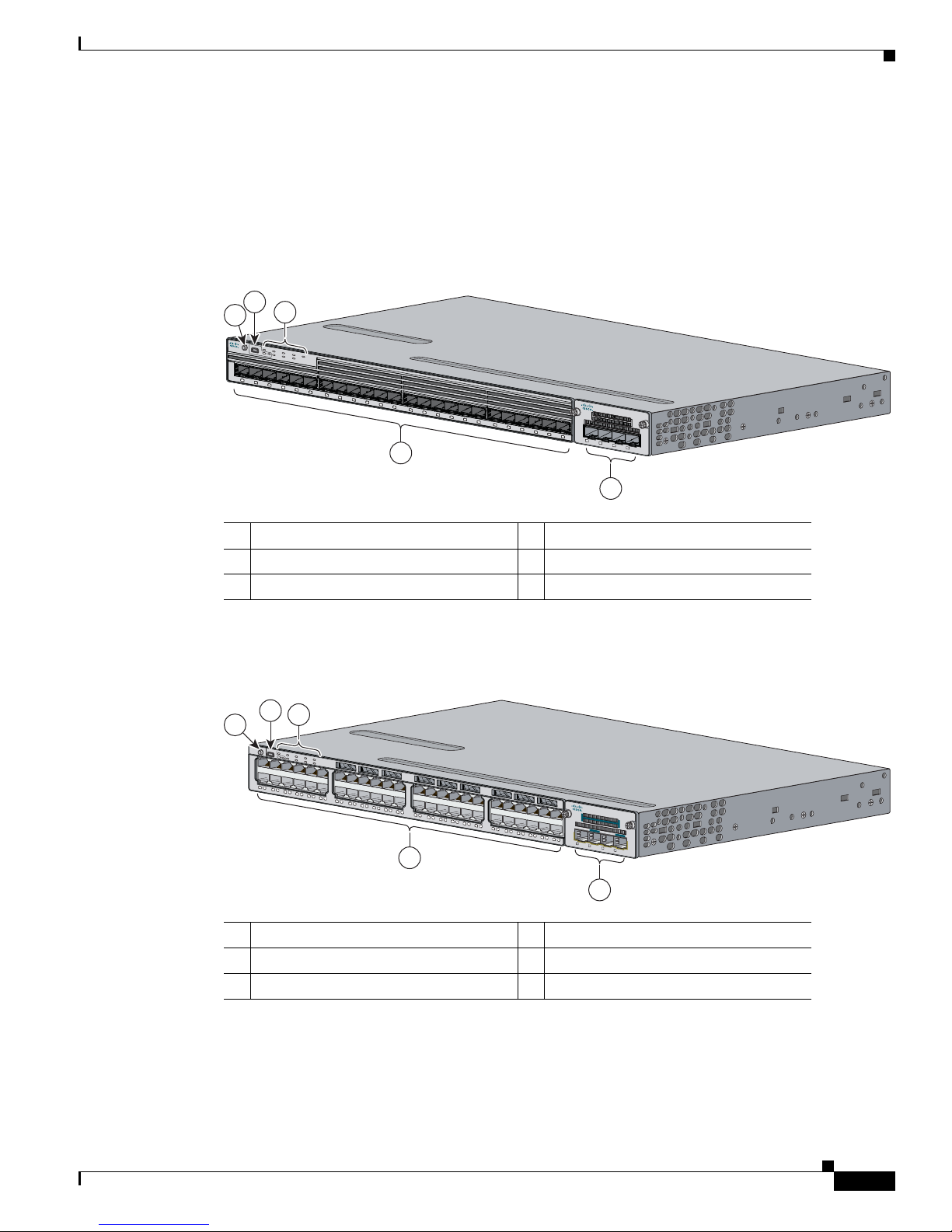
Front Panel Description
The switch front panel includes the Mode button, a USB 5-pin mini-Type B console port, the downlink
ports and LEDs, the network module, and the switch LEDs.
Figure 1-1 shows the Catalyst 3750-X-24S switch as an example.
Figure 1-1 Catalyst 3750-X-24S Switch Front Panel
2
1
3
CO
N
S
OL
E
S
Y
S
T
X
P
M
S
O
DE
E
N
S
T
AT
S
S
P
PW
E
E
D
R
P
o
E
D
MAST
UP
L
X
S
T
AC
K
Cata
l
y
s
t
3
7
50-X Series
1
2
3
4
5
6
7
8
9
10
Front Panel Description
1
1
12
1
3
14
15
16
17
18
19
20
21
22
2
3
4
C
3
K
X-N
M
-1G
NETW
OR
K
M
ODU
LE
24
G1
G2
G3
G4
282317
5
1 Mode button 4 SFP module slots (downlink)
2 USB Type-B console port 5 Network Module
3 Status LEDs
Figure 1-2 shows the Catalyst 3750-X-48P switch as an example.
Figure 1-2 Catalyst 3750-X-48P Switch Front Panel
1 Mode button 4 10/100/1000 ports
2 USB Type-B console port 5 Network Module
3 Status LEDs
OL-19593-03
Catalyst 3750-X and 3560-X Switch Hardware Installation Guide
1-5

Front Panel Description
SFP Module Slots
The switch (downlink) SFP module slots on the Catalyst 3750-X-12S and Catalyst 3750-X-24S switch
support any combination of standard SFP modules. SFP+ modules are not supported.
Chapter 1 Product Overview
Note
For information about about the (uplink) SFP and SFP+ module slots on the network modules, see the
“Network Modules” section on page 1-7.
See Tabl e 1-4 for a list of supported SFP modules.
10/100/1000 Ethernet Ports
The 10/100/1000 Ethernet ports use RJ-45 connectors with Ethernet pinouts. The maximum cable length
is 328 feet (100 meters). The 100BASE-TX and 1000BASE-T traffic requires Category 5, Category 5e,
or Category 6 unshielded twisted pair (UTP) cable. The 10BASE-T traffic can use Category 3 or
Category 4 UTP cable.
For information about the 10/100/1000 Ethernet port connections and specifications, see the
“10/100/1000 Ethernet Port Connections” section on page 2-27 and Appendix B, “Connector and Cable
Specifications.”
PoE+ and UPOE Ports
The PoE+ and UPOE ports use the same connectors as described in the “10/100/1000 Ethernet Ports”
section on page 1-6 and provide this support.
•
Support for prestandard Cisco powered devices
•
Support for IEEE 802.3af compliant powered devices (up to 15.4 W)
•
Support for IEEE 802.3at compliant powered devices (up to 30 W)
1-6
•
Support for Cisco UPOE (up to 60 W) —UPOE switches only
•
Support for Cisco enhanced PoE
•
Configuration for StackPower PoE+ and UPOE. When the switch internal power supply module(s)
cannot support the total load, StackPower configurations allow the switch to leverage power
available from other switches (only Catalyst 3750-X switches)
•
Configurable support for Cisco intelligent power management, including enhanced power
negotiation, power reservation, and per-port power policing
See Tab l e 1- 1 8 for the power supply matrix that defines the available PoE, PoE+, and UPOE power per
port.
Note
Catalyst 3750-X and 3560-X Switch Hardware Installation Guide
The output of the PoE+ and UPOE circuit has been evaluated as a Limited Power Source (LPS) per IEC
60950-1.
For information about power supply modules, PoE+ port connections, and PoE+ specifications, see the
“Power Supply Modules” section on page 1-20, the “PoE+ and UPOE Port Connections” section on
page 2-27, and Appendix B, “Connector and Cable Specifications.”
OL-19593-03
Chapter 1 Product Overview
Network Modules
The switch supports one hot-swappable network module that provides uplink ports to connect to other
devices. You must insert the network module during switch operation. Operating the switch without a
network module is not supported. A blank module is available.
The switch generates logs when you insert or remove a network module with SFP ports.
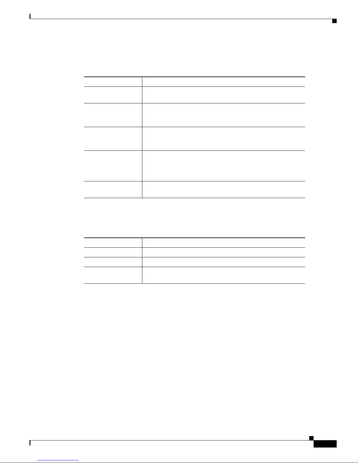
Table 1-3 Network Modules
Front Panel Description
Network Module
10-Gigabit Ethernet
C3KX-NM-10G
1
Description
This module has four slots. Two slots support only 1-Gigabit SFP modules, two
slots support either 1-Gigabit SFP or 10-Gigabit SFP+ modules.
Note
The GLC-T SFP is not supported on the SFP+ slots of C3KX-NM-10G.
The four slots are grouped as two pairs with each pair consisting of one SFP slot
and one SFP+ slot. Each pair supports either two 1-Gigabit SFP modules or one
10-Gigabit SFP+ module. A 10-Gigabit SFP+ module cannot operate at the same
time as the corresponding 1-Gigabit SFP module in the pair.
Supported combinations of SFP and SFP+ modules:
•
Slots 1, 2, 3, and 4 populated with 1-Gigabit SFP modules.
•
Slots 1 and 2 populated with 1-Gigabit SFP modules and Slot 4 populated
with one 10-Gigabit SFP+ module.
•
Slot 2 populated with one 10-Gigabit SFP+ module and Slots 3 and 4
populated with 1-Gigabit SFP modules.
•
Slot 2 and Slot 4 each populated with 10-Gigabit SFP+ modules.
A 10-Gigabit SFP+ module takes precedence over a 1-Gigabit SFP module
except when an SFP module is first inserted in Slot 1 and has link. When you
insert an SFP+ module in Slot 2, the SFP in Slot 1 retains link. The SFP+ module
in Slot 2 does not operate.
When the SFP module in Slot 1 is shutdown, loses link, or is removed, the SFP+
module in Slot 2 becomes operational. At this point, the SFP module in Slot 1
will not become operational under any circumstance for as long as an SFP+
module remains in Slot 2 whether it is link up or not.
The same precedence applies to Slots 3 and 4.
10-Gigabit Ethernet
This module has two autonegotiating 10-Gigabit Ethernet (copper) ports.
C3KX-NM-10GT
10-Gigabit Ethernet
Service Module
C3KX-SM-10G
1-Gigabit Ethernet
C3KX-NM-1G
This module has two slots that support either 1-Gigabit SFP or 10-Gigabit SFP+
modules. The service module supports Net Flow and MACSec Uplink
Encryption (switch- to-switch encryption between uplinks).
This module has four 1-Gigabit SFP module slots. Any combination of standard
SFP modules are supported. SFP+ modules are not supported. If you insert an
SFP+ module in the 1-Gigabit network module, the SFP+ module does not
operate, and the switch logs an error message.
Blank
This module has no uplink ports.
C3KX-NM_BLNK
1. All network modules are hot-swappable.
OL-19593-03
Catalyst 3750-X and 3560-X Switch Hardware Installation Guide
1-7
Front Panel Description
For information about the network modules, see the “Installing a Network Module in the Switch” section
on page 2-22. For cable specifications, see Appendix B, “Connector and Cable Specifications.”
SFP and SFP+ Modules
The SFP and SFP+ modules provide copper or fiber-optic connections to other devices. These
transceiver modules are field-replaceable, providing the uplink interfaces when installed in an SFP
module slot. The SFP modules have LC connectors for fiber-optic connections or RJ-45 connectors for
copper connections.
Use only Cisco SFP modules on the switch.
Chapter 1 Product Overview
Note
The (downlink) SFP module slots on the Catalyst 3750-X-12S and Catalyst 3750-X-24S switch front
panel support any combination of standard SFP modules. SFP+ modules are not supported.
Table 1-4 Supported Cisco SFP Modules
Part Number Description
GLC-GE-100FX=
1,2,3
100FX SFP on GE SFP ports for LAN switches
GLC-LH-SM= GE SFP, LC connector LX/LH transceiver
GLC-LH-SMD= GE SFP, LC connector LX/LH transceiver, extended operating temperature
range
GLC-SX-MM= GE SFP, LC connector SX transceiver
GLC-SX-MMD= GE SFP, LC connector SX transceiver, extended operating temperature
range
GLC-T=
1, 3
1000BASE-T SFP transceiver module for copper connections
GLC-ZX-SM= 1000BASE-ZX SFP module for SMF, 1550 nm
GLC-BX-D=
1
1000BASE-BX10 SFP module for single-strand SMF, 1490-nm TX,
1310-nm RX wavelength
GLC-BX-U=
1
1000BASE-BX10 SFP module for single-strand SMF, 1310-nm TX,
1490-nm RX wavelength
Catalyst 3750-X and 3560-X Switch Hardware Installation Guide
1-8
OL-19593-03
Chapter 1 Product Overview
Table 1-4 Supported Cisco SFP Modules (continued)
Part Number Description
CWDM-SFP-1470= CWDM 1470-nm SFP Gigabit Ethernet and 1G/2G FC
CWDM-SFP-1490= CWDM 1490-nm SFP Gigabit Ethernet and 1G/2G FC
CWDM-SFP-1510= CWDM 1510-nm SFP Gigabit Ethernet and 1G/2G FC
CWDM-SFP-1530= CWDM 1530-nm SFP Gigabit Ethernet and 1G/2G FC
CWDM-SFP-1550= CWDM 1550-nm SFP Gigabit Ethernet and 1G/2G FC
CWDM-SFP-1570= CWDM 1570-nm SFP Gigabit Ethernet and 1G/2G FC
CWDM-SFP-1590= CWDM 1590-nm SFP Gigabit Ethernet and 1G/2G FC
CWDM-SFP-1610= CWDM 1610-nm SFP Gigabit Ethernet and 1G/2G FC
SFP-GE-S= 1000BASE-SX SFP module for MMF, 850 nm (DOM)
SFP-GE-L= 1000BASE-LX/LH SFP module for SMF, 1300 nm (DOM)
DWDM-SFP-3033= DWDM SFP 1530.33-nm SFP (100 GHz ITU grid)
DWDM-SFP-3112= DWDM SFP 1531.12-nm SFP (100 GHz ITU grid)
DWDM-SFP-3190= DWDM SFP 1531.90-nm SFP (100 GHz ITU grid)
DWDM-SFP-3268= DWDM SFP 1532.68-nm SFP (100 GHz ITU grid)
DWDM-SFP-3346= DWDM SFP 1533.47-nm SFP (100 GHz ITU grid)
DWDM-SFP-3425= DWDM SFP 1534.25-nm SFP (100 GHz ITU grid)
DWDM-SFP-3504= DWDM SFP 1535.04-nm SFP (100 GHz ITU grid)
DWDM-SFP-3582= DWDM SFP 1535.82-nm SFP (100 GHz ITU grid)
DWDM-SFP-3661= DWDM SFP 1536.61-nm SFP (100 GHz ITU grid)
DWDM-SFP-3739= DWDM SFP 1537.40-nm SFP (100 GHz ITU grid)
DWDM-SFP-3819= DWDM SFP 1538.19-nm SFP (100 GHz ITU grid)
DWDM-SFP-3898= DWDM SFP 1538.98-nm SFP (100 GHz ITU grid)
DWDM-SFP-3977= DWDM SFP 1539.77-nm SFP (100 GHz ITU grid)
DWDM-SFP-4056= DWDM SFP 1540.56-nm SFP (100 GHz ITU grid)
DWDM-SFP-4134= DWDM SFP 1541.35-nm SFP (100 GHz ITU grid)
DWDM-SFP-4214= DWDM SFP 1542.14-nm SFP (100 GHz ITU grid)
DWDM-SFP-4294= DWDM SFP 1542.94-nm SFP (100 GHz ITU grid)
DWDM-SFP-4373= DWDM SFP 1543.73-nm SFP (100 GHz ITU grid)
DWDM-SFP-4453= DWDM SFP 1544.53-nm SFP (100 GHz ITU grid)
DWDM-SFP-4532= DWDM SFP 1545.32-nm SFP (100 GHz ITU grid)
DWDM-SFP-4612= DWDM SFP 1546.12-nm SFP (100 GHz ITU grid)
Front Panel Description
4
4
OL-19593-03
Catalyst 3750-X and 3560-X Switch Hardware Installation Guide
1-9
Front Panel Description
Chapter 1 Product Overview
Table 1-4 Supported Cisco SFP Modules (continued)
Part Number Description
DWDM-SFP-4692= DWDM SFP 1546.92-nm SFP (100 GHz ITU grid)
DWDM-SFP-4772= DWDM SFP 1547.72-nm SFP (100 GHz ITU grid)
DWDM-SFP-4851= DWDM SFP 1548.51-nm SFP (100 GHz ITU grid)
DWDM-SFP-4931= DWDM SFP 1549.32-nm SFP (100 GHz ITU grid)
DWDM-SFP-5012= DWDM SFP 1550.12-nm SFP (100 GHz ITU grid)
DWDM-SFP-5092= DWDM SFP 1550.92-nm SFP (100 GHz ITU grid)
DWDM-SFP-5172= DWDM SFP 1551.72-nm SFP (100 GHz ITU grid)
DWDM-SFP-5252= DWDM SFP 1552.52-nm SFP (100 GHz ITU grid)
DWDM-SFP-5332= DWDM SFP 1553.33-nm SFP (100 GHz ITU grid)
DWDM-SFP-5413= DWDM SFP 1554.13-nm SFP (100 GHz ITU grid)
DWDM-SFP-5494= DWDM SFP 1554.94-nm SFP (100 GHz ITU grid)
DWDM-SFP-5575= DWDM SFP 1555.75-nm SFP (100 GHz ITU grid)
DWDM-SFP-5655= DWDM SFP 1556.55-nm SFP (100 GHz ITU grid)
DWDM-SFP-5736= DWDM SFP 1557.36-nm SFP (100 GHz ITU grid)
DWDM-SFP-5817= DWDM SFP 1558.17-nm SFP (100 GHz ITU grid)
DWDM-SFP-5898= DWDM SFP 1558.98-nm SFP (100 GHz ITU grid)
DWDM-SFP-5979= DWDM SFP 1559.79-nm SFP (100 GHz ITU grid)
DWDM-SFP-6061= DWDM SFP 1560.61-nm SFP (100 GHz ITU grid)
DWDM-SFP-6141= DWDM SFP 1561.42-nm SFP (100 GHz ITU grid)
1. Not supported in the SFP+ slots (2 and 4) on the C3KX-NM-10G.
2. Not supported on the C3KX-SM-10G
3. Not supported for NEBS.
4. DOM = digital optical monitoring.
Table 1-5 Supported Cisco SFP+ Modules
Part Number Description
SFP-10G-LR= 10 GBASE LR SFP+ transceiver module for SMF, 1350 nm,
SFP-10G-SR= 10 GBASE SR SFP+ transceiver module for MMF, 850 nm,
SFP-10G-LRM= 10 GBASE-LRM SFP+ module for MMF and SMF, 1310 nm
SFP-H10GB-CU1M= 10 GBASE-CU Twinax SFP+ cable assembly, 1 meter (Version -02)
SFP-H10GB-CU3M= 10 GBASE-CU Twinax SFP+ cable assembly, 3 meters (Version -02)
SFP-H10GB-CU5M= 10 GBASE-CU Twinax SFP+ cable assembly, 5 meters (Version -02)
Catalyst 3750-X and 3560-X Switch Hardware Installation Guide
1-10
LC duplex connector
LC duplex connector
OL-19593-03
Chapter 1 Product Overview
LEDs
Front Panel Description
For information about SFP modules, see your SFP module documentation and the “Installing SFP and
SFP+ Modules” section on page 2-24. For cable specifications, see Appendix B, “Connector and Cable
Specifications.”
The Catalyst 3560-X switch supports the SFP module patch cable (CAB-SFP-50CM), a 0.5-meter,
copper, passive cable with SFP module connectors at each end. This cable is only used with 1-Gigabit
Ethernet SFP ports to connect two Catalyst 3560-X switches in a cascaded configuration.
You can use the switch LEDs to monitor switch activity and its performance. Figure 1-3 shows the
Catalyst 3750-X switch LEDs and the Mode button that you use to select a port mode.
Figure 1-3 Switch Front Panel LEDs
1
2
3
4
SPEED
STACK
5
DUPLX
PoE
MODE
CONSOLE
SYST
XPS
EN
S-PWR
STAT
MAST
System LED
1
2
3
4
5
6
7
8
9
10
11
6
7
8
9
12
251962
10
1 System LED 6 USB console port LED
2 XPS
1
LED
7 S-PWR (StackPower) LED
3 Status LED 8 Master LED
4 Speed LED 9 Stack LED
5 Duplex LED 10 PoE LED
1. XPS = Expandable power system.
2. Only Catalyst 3750-X switches.
3. Only switches with PoE+ or UPOE ports.
Table 1-6 System LED
2
2
3
2
Color System Status
Off System is not powered on.
Green System is operating normally.
Blinking Green Switch is running power on self-test (POST).
Amber System is receiving power but is not functioning properly.
OL-19593-03
Catalyst 3750-X and 3560-X Switch Hardware Installation Guide
1-11
Front Panel Description
XPS LED
Chapter 1 Product Overview
For information on the System LED colors during power-on self-test (POST), see the “Diagnosing
Problems” section on page 4-1.
Ta b l e 1 - 7 X P S L E D
Color XPS Status
Off XPS cable is not installed.
Switch is in StackPower mode (Catalyst 3750-X).
Green XPS is connected and ready to provide back-up power.
Blinking green XPS is connected but is unavailable because it is providing power to another device
(redundancy has been allocated to a neighboring device).
Amber The XPS is in standby mode or in a fault condition. See the XPS 2200
documentation for information about the standby mode and fault conditions.
Blinking amber The power supply in a switch has failed, and the XPS is providing power to that
switch (redundancy has been allocated to this device).
For information about the XPS 2200, see the Cisco eXpandable Power System 2200 Hardware
Installation Guide on Cisco.com.
Port LEDs and Modes
Each Ethernet port, 1-Gigabit Ethernet module slot, and 10-Gigabit Ethernet module slot has a port LED.
These port LEDs, as a group or individually, display information about the switch and about the
individual ports. The port mode determines the type of information shown by the port LEDs. Table 1 - 8
lists the mode LEDs and their associated port modes and meanings.
To select or change a mode, press the Mode button until the desired mode is highlighted. When you
change port modes, the meanings of the port LED colors also change. Table 1 - 9 explains how to interpret
the port LED colors in different port modes.
When you press the Mode button on any switch in the Catalyst 3750-X switch stack, all the stack
switches change to show the same selected mode. For example, if you press the Mode button on the stack
master to show the SPEED LED, all the other switches in the stack also show the SPEED LED.
Table 1-8 Port Mode LEDs
Mode LED Port Mode Description
STAT Port status The port status. This is the default mode.
SPEED Port speed The port operating speed: 10, 100, or 1000 Mb/s.
DUPLX Port duplex mode The port duplex mode: full duplex or half duplex.
MAST
1
Master The stack master status.
Catalyst 3750-X and 3560-X Switch Hardware Installation Guide
1-12
OL-19593-03
Chapter 1 Product Overview
Table 1-8 Port Mode LEDs (continued)
Mode LED Port Mode Description
STACK
PoE
1. Only Catalyst 3750-X switches.
2. Only switches with PoE+ or UPOE ports.
Table 1-9 Meaning of Switch LED Colors in Different Modes
Port Mode Port LED Color Meaning
STAT
(port status)
Front Panel Description
1
Stack member status
StackWise port status
The stack member status.
The StackWise port status. See the “Stack LED (Catalyst
3750-X)” section on page 1-15.
2
PoE+ or UPOE port
The PoE+ or UPOE port status.
power
Off No link, or port was administratively shut down.
Green Link present, no activity.
Blinking green Activity. Port is sending or receiving data.
Alternating
green-amber
Link fault. Error frames can affect connectivity, and errors such as
excessive collisions, CRC errors, and alignment and jabber errors
are monitored for a link-fault indication.
Amber Port is blocked by Spanning Tree Protocol (STP) and is not
forwarding data.
SPEED
DUPLX
(duplex)
1
MAST
(data stack
master)
After a port is reconfigured, the port LED can be amber for up to 30
seconds as STP checks the switch for possible loops.
10/100/1000/SFP ports
Off Port is operating at 10 Mb/s.
Green Port is operating at 100 Mb/s.
Single green
Port is operating at 1000 Mb/s.
flash (on for
100 ms, off for
1900 ms)
Network module slots
Off Port is not operating.
Blinking green Port is operating at up to 10 Gb/s.
Off Port is operating in half duplex.
Green Port is operating in full duplex.
Off The switch is not the stack master.
Note
For a standalone switch, this LED is off.
Green The switch is the stack master.
Amber Error during stack master election.
OL-19593-03
Catalyst 3750-X and 3560-X Switch Hardware Installation Guide
1-13
Front Panel Description
Chapter 1 Product Overview
Table 1-9 Meaning of Switch LED Colors in Different Modes (continued)
Port Mode Port LED Color Meaning
STACK
(stack member)
1
Off No stack member corresponding to that member number.
Blinking green Stack member number.
Green Member numbers of other stack member switches.
PoE
2
Off PoE+ or UPOE is off.
If the powered device is receiving power from an AC power source,
the port LED is off even if the device is connected to the switch port.
Green PoE+ or UPOE
is on. The port LED is green when the switch port
is providing power.
Alternating
green and
PoE+ or UPOE is denied because providing power to the powered
device will exceed the switch power capacity.
amber
Blinking amber PoE+ or UPOE is off due to a fault or because it has exceeded a limit
set in the switch software.
USB Console LED
Caution
PoE+ and or UPOE faults are caused when noncompliant
cabling or powered devices are connected to a PoE+ or
UPOE port. Use only standard-compliant cabling to
connect Cisco prestandard IP Phones and wireless access
points or IEEE 802.3af-compliant devices to PoE+ or
UPOE ports. You must remove from the network any
cable or device that causes a PoE+ or UPOE fault.
Amber PoE+ or UPOE for the port has been disabled.
Note
1. Only Catalyst 3750-X switches.
2. Only switches with PoE+ or UPOE ports.
PoE+ or UPOE is enabled by default.
The USB console LED shows whether there is an active USB connection to the port.
Table 1-10 USB Console Port LED
Color Description
Off USB console is disabled.
Green USB console is enabled.
Catalyst 3750-X and 3560-X Switch Hardware Installation Guide
1-14
OL-19593-03
Chapter 1 Product Overview
S-PWR LED (Catalyst 3750-X)
Ta b l e 1 - 11 S - PW R L ED
Color Description
Off StackPower cable is not connected, or the switch is in standalone
Green An XPS cable is connected to the XPS 2200.
Blinking Green This appears on the switch in a StackPower ring configuration
Amber There is a fault: load shedding is occurring, a StackPower cable is
Blinking Amber The StackPower budget is not sufficient to meet current power
Front Panel Description
mode.
Each StackPower port is connected to another switch or to an XPS
2200 (Catalyst 3750-X switches).
that detects an open ring or has only one StackPower cable
connected, and no connection to an XPS 2200.
defective, or administrative action is required. See the switch
software configuration guide for information about configuring
StackPower.
demands.
Master LED (Catalyst 3750-X)
Ta b l e 1 - 1 2 M a s t e r L E D
Color Description
Off Switch is not the stack master.
Green Switch is the stack master or a standalone switch.
Amber An error occurred when the switch was selecting the stack master
Stack LED (Catalyst 3750-X)
The stack LED shows the sequence of member switches in a stack. Up to nine switches can be members
of a stack. The first nine port LEDs show the member number of a switch in a stack. Figure 1-4 shows
the LEDs on the first switch, which is stack member number 1. For example, if you press the Mode
button and select Stack, the LED for port 1 blinks green. The LEDs for ports 2 and 3 are solid green, as
these represent the member numbers of other switches in the stack. The other port LEDs are off because
there are no more members in the stack.
switch, or another type of stack error occurred.
OL-19593-03
Catalyst 3750-X and 3560-X Switch Hardware Installation Guide
1-15
Front Panel Description
253198
Catalyst 3750-X PoE+48
SYST
XPS
STAT
SPEED
DUPLX
EN
PoE
STACK
MAST
S-PWR
MODE
CONSOLE
1
2
3
4
5
6
7
8
9
10
11
12
1
2
3
4
5
6
7
8
9
10
11
12
1
2
3
4
5
6
7
8
9
10
11
12
1
2
3
4
5
6
7
8
9
10
11
12
C3KX-NM-10G
NETWORK
MODULE
G1
G2/TE1
G3
G4/TE2
Catalyst 3750-X PoE+48
SYST
XPS
STAT
SPEED
DUPLX
EN
PoE
STACK
MAST
S-PWR
MODE
CONSOLE
1
2
3
4
5
6
7
8
9
10
11
12
1
2
3
4
5
6
7
8
9
10
11
12
1
2
3
4
5
6
7
8
9
10
11
12
1
2
3
4
5
6
7
8
9
10
11
12
C3KX-NM-10G
NETWORK
MODULE
G1
G2/TE1
G3
G4/TE2
Catalyst 3750-X PoE+48
SYST
XPS
STAT
SPEED
DUPLX
EN
PoE
STACK
MAST
S-PWR
MODE
CONSOLE
1
2
3
4
5
6
7
8
9
10
11
12
1
2
3
4
5
6
7
8
9
10
11
12
1
2
3
4
5
6
7
8
9
10
11
12
1
2
3
4
5
6
7
8
9
10
11
12
C3KX-NM-10G
NETWORK
MODULE
G1
G2/TE1
G3
G4/TE2
SYST
XPS
STAT
SPEED
DUPLX
PoE
STACK
MAST
S-PWR
MODE
CONSOLE
1
2
3
4
5
6
7
8
9
10
11
12
EN
5
6
4
1
2
3
Chapter 1 Product Overview
Figure 1-4 Stack LED
1 Stack member 1 4 LED blinks green to show that this is switch 1 in the stack.
2 Stack member 2 5 LED is solid green to show that switch 2 is a stack member.
3 Stack member 3 6 LED is solid green to show that switch 3 is a stack member.
When you select the Stack LED mode, the representative Stack LEDs are green when the StackWise
ports are up, and the representative Stack LEDs are amber when the ports are down.
PoE LED
If the PoE LED mode is not selected on a switch with PoE+ or UPOE ports, the PoE LED still shows
detected PoE+ or UPOE problems.
Table 1-13 PoE Mode LED
Color PoE+/UPOE Status
Off PoE+ or UPOE mode is not selected. None of the 10/100/1000 ports have been
Green PoE+ or UPOE mode is selected, and the port LEDs show the PoE+ or UPOE
Blinking amber PoE+ or UPOE mode is not selected. At least one of the 10/100/1000 ports has been
1-16
Catalyst 3750-X and 3560-X Switch Hardware Installation Guide
denied power or are in a fault condition.
status.
denied power, or at least one of the 10/100/1000 ports has a PoE+ or UPOE fault.
OL-19593-03
Chapter 1 Product Overview
Catalyst 3750-X PoE+48
37
38
39
40
41
42
43
44
45
46
47
48
C3KX-NM-10G
NETWORK
MODULE
G1
G2/TE1
G3
G4/TE2
253212
1
2
3
4
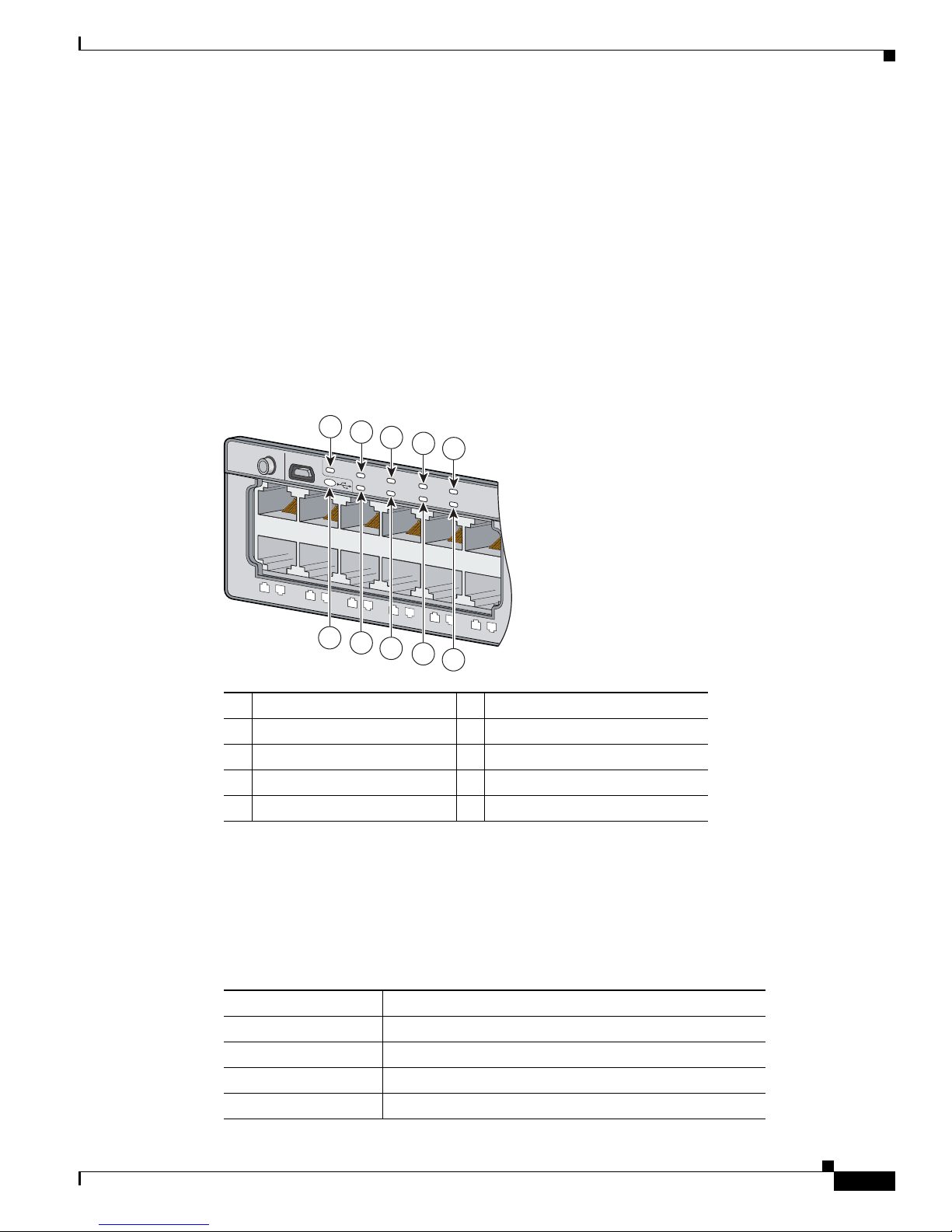
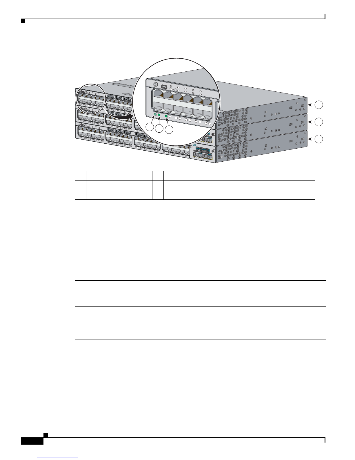
Network Module LEDs
Figure 1-5 Network Module LEDs (10-Gigabit Network Module Shown)
1 G1 LED 3 G3 LED
2 G2/TE1 LED 4 G4/TE2 LED
Table 1-14 Network Module LEDs
Front Panel Description
Color Network Module Link Status
Off Link is off.
Green Link is on, no activity.
Blinking green Activity on a link, no faults.
Blinking amber Link is off due to a fault or because it has exceeded a limit set in the
switch software.
Caution
Link faults are caused when noncompliant cabling is
connected to an SFP or SFP+ port. Use only
standard-compliant cabling to connect to Cisco SFP and
SFP+ ports. You must remove from the network any cable
or device that causes a link fault.
Amber Link for the SFP or SFP+ has been disabled.
OL-19593-03
Catalyst 3750-X and 3560-X Switch Hardware Installation Guide
1-17
Rear Panel Description
253163
R
E
S
ET
C
ONSOLE
STACK 1
STACK 2
AUX
A
C
OK
C3KX
-P
WR-715W
AC
PS
OK
A
C
OK
C3KX
-P
WR
-715W
AC
PS
OK
S-PWR
XPS
S
-
PW
R
1
3
4
5
6
7
8
9
10
11
12
13
12
251961
13
2
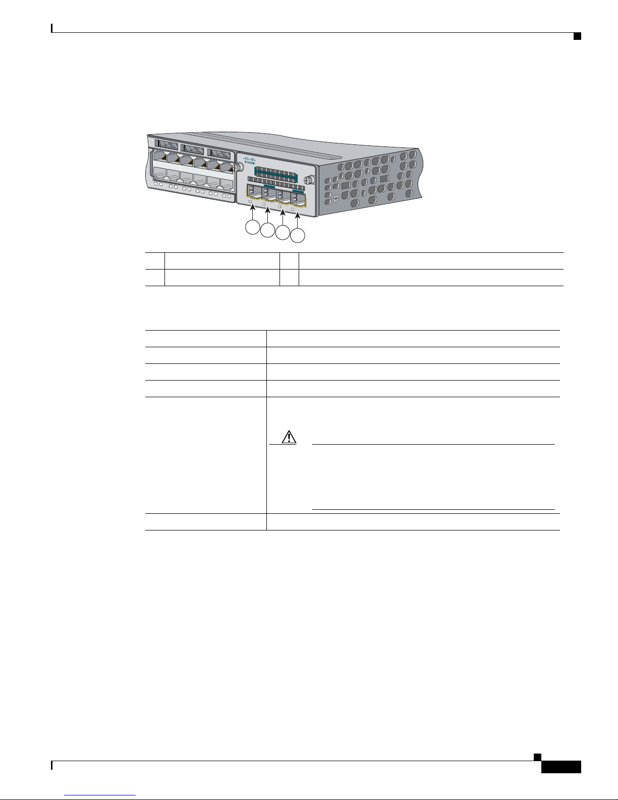
USB Mini-Type B Port
A USB 5-pin mini-Type B connector on the front panel is available for switch management (Figure 1-6).
Figure 1-6 USB Mini-Type B Console Port
See the “Management Ports” section on page 1-24 for details.
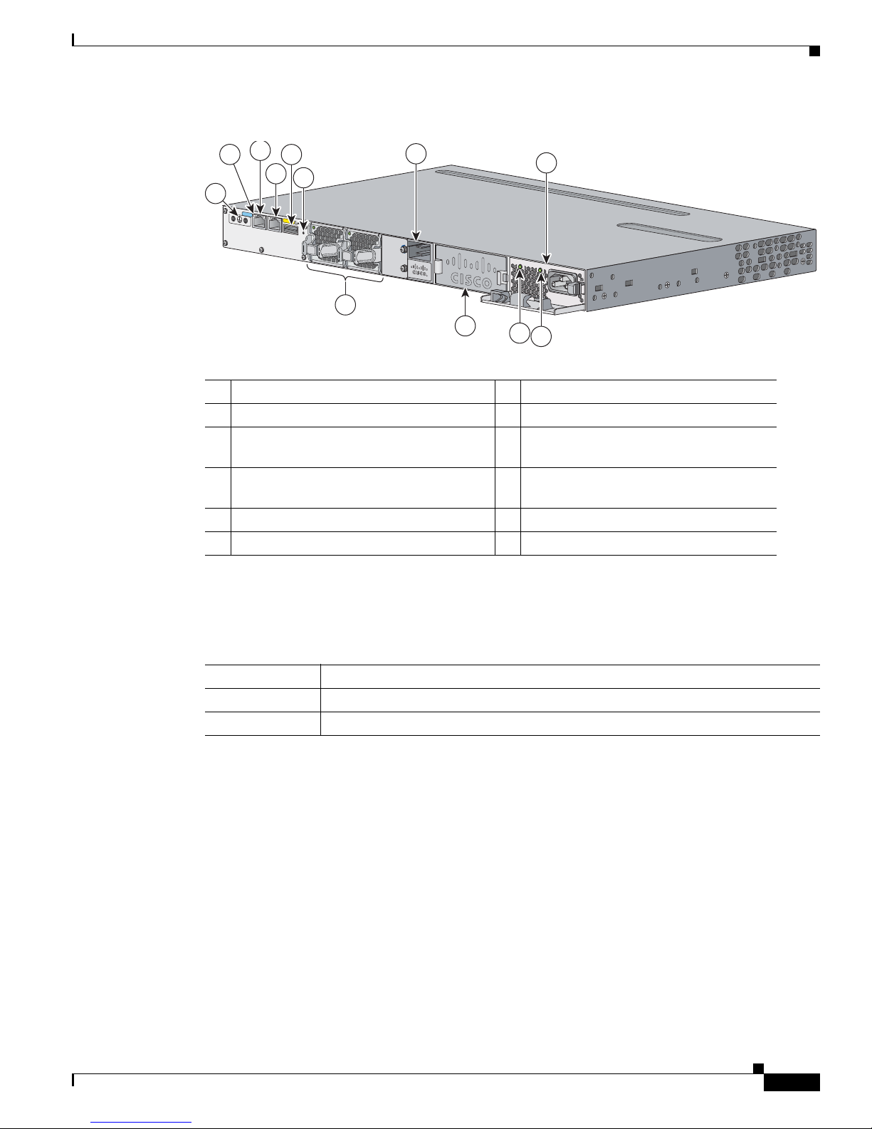
Rear Panel Description
The switch rear panel has a ground connector, an RJ-45 console port, an RJ-45 10/100 management port,
a USB Type A connector, two StackWise connectors (only Catalyst 3750-X switches), two fan modules,
an XPS 2200 connector, a StackPower connector (only Catalyst 3750-X switches), and two power supply
module slots. See Figure 1-7, and the descriptions on the following pages. Figure 1-7 shows the Catalyst
3750-X-48 PoE+ switch, which has one connector for either a StackPower or an XPS connection, and
one connector only for StackPower. Figure 1-8 shows the Catalyst 3560-X switch rear panel, which has
one connector for XPS and no StackPower connector.
Chapter 1 Product Overview
Figure 1-7 Catalyst 3750-X Switch Rear Panel
1 Ground connector 8 Fan modules
2 RJ-45 console port LED 9 StackPower or XPS 2200 connector
3 RJ-45 console port 10 StackPower connector
4 RJ-45 10/100 management port 11 Power supply modules (AC power supply
5 USB Type A connector 12 AC power (input) status LED
1-18
6 Stack cable connectors 13 Power supply (output) status LED
7 Reset button
Catalyst 3750-X and 3560-X Switch Hardware Installation Guide
modules shown)
OL-19593-03
Chapter 1 Product Overview
RES
ET
S
E
R
IA
L
XPS
A
C
OK
C3K
X
-P
WR-715W
AC
PS
OK
CON
SOLE
10
/100T
X
1
3
4
5
6
7
8
11
253392
12
2
9
10
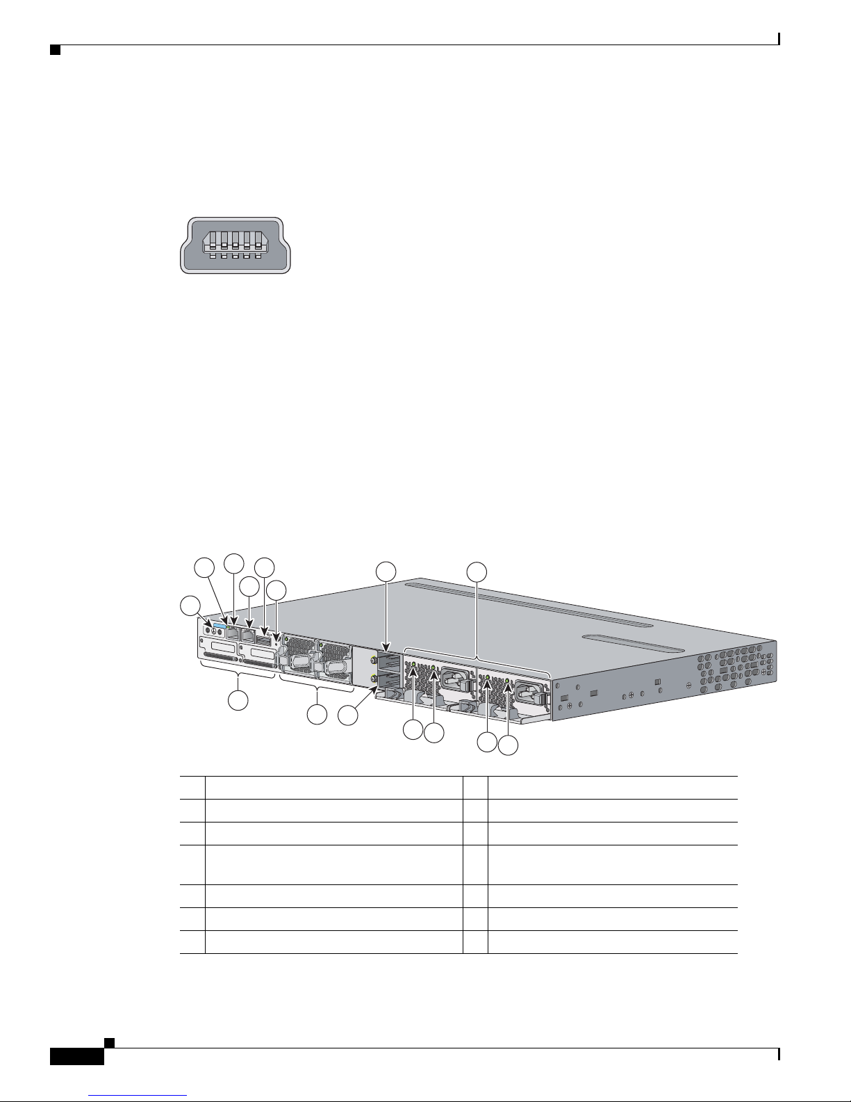
Figure 1-8 Catalyst 3560-X Switch Rear Panel
1 Ground connector 7 Fan modules
2 RJ-45 console port LED 8 XPS 2200 connector
3 RJ-45 console port 9 Power supply module slot (blank module
4 RJ-45 10/100 management port 10 Power supply module (AC power supply
5 USB Type A connector 11 AC power (input) status LED
6 Reset button 12 Power supply (output) status LED
Rear Panel Description
shown)
module shown)
RJ-45 Console Port LED
Table 1-15 RJ-45 Console Port LED
Color RJ-45 Console Port Status
Off RS-232 console is disabled.
Green RS-232 console is enabled.
USB Type A Interface
The USB Type A interface provides access to external USB FLASH devices (also known as thumb drives
or USB keys).
The interface supports Cisco USB flash drives with capacities from 64 MB to 1 GB.
Cisco IOS software provides standard file system access to the flash device: read, write, erase, and copy,
as well as formatting of the flash device with a FAT file system. You can boot the switch from a USB
drive.
OL-19593-03
For information about the switch management ports, see the switch software configuration guide and the
command reference on Cisco.com and the “Connector and Cable Specifications” section on page B-1.
Catalyst 3750-X and 3560-X Switch Hardware Installation Guide
1-19
Rear Panel Description
StackWise Ports
The Catalyst 3750-X switch ships with a 0.5-meter StackWise cable (CAB-STACK-50CM) that you can
use to connect the StackWise ports.
Chapter 1 Product Overview
Caution
Use only approved cables (CAB-STACK-50CM, CAB-STACK-1M, CAB-STACK-3M,
CAB-STACK-50CM-NH,CAB-STACK-1M-NH, or CAB-STACK-3M-NH), and connect only to similar
Cisco equipment. Equipment might be damaged if connected to nonapproved Cisco cables or equipment.
You can order these StackWise cables from your Cisco sales representative:
•
CAB-STACK-50CM (0.5-meter cable)
•
CAB-STACK-1M= (1-meter cable)
•
CAB-STACK-3M= (3-meter cable)
•
CAB-STACK-50CM-NH= (0.5-meter cable, nonhalogen)
•
CAB-STACK-1M-NH= (1-meter cable, nonhalogen)
•
CAB-STACK-3M-NH= (3-meter cable, nonhalogen)
Power Supply Modules
The switch is powered through one or two internal power supply modules.
Supported power supply modules:
Description Model
350 W AC PWR-C1-350WAC
715 W AC PWR-C1-715WAC1
1100 W AC PWR-C1-1100WAC
440 W DC PWR-C1-440WDC
1. These power supplies have an extended tab at the connector end that is designed to protect the system and the
power supply from damage if the power supply is installed incorrectly. Otherwise, these power supplies are
functionally compatible with the C3KX-PWR power supplies.
1
C3KX-PWR-350WAC
C3KX-PWR-715WAC
1
C3KX-PWR-1100WAC
1
C3KX-PWR-440WDC
The switch has two internal power supply module slots. You can use two AC modules, two DC modules,
a mixed configuration of one AC and one DC power supply module, or one power supply module and a
blank module.
The switch can operate with either one or two active power supply modules or with power supplied by
an XPS 2200. A Catalyst 3750-X switch that is in a StackPower stack can operate with power supplied
by other switches in the stack.
Table 1-1 and Tab le 1 -2 show the power supply modules that ship with each switch model. All power
supply modules (except the blank modules) have internal fans. All switches ship with a blank power
supply module in the second power supply slot.
Catalyst 3750-X and 3560-X Switch Hardware Installation Guide
1-20
OL-19593-03
Chapter 1 Product Overview
Rear Panel Description
Caution
Do not operate the switch with one power supply module slot empty. For proper chassis cooling, both
power supply module slots must be populated or with either a power supply or a blank module.
The 350-W and 715-W AC power supply modules are autoranging units that support input voltages
between 100 and 240 VAC. The 1100-W power supply module is an autoranging unit that supports input
voltages between 115 and 240 VAC. The 440-W DC power supply module has dual input feeds (A and B)
and supports input voltages between 36 and 72 VDC. The output voltage range is 51–57 V.
Each AC power supply module has a power cord for connection to an AC power outlet. The 1100-W and
715-W modules use a 16-AWG cord (only North America). All other modules use an 18-AWG cord. The
DC-power supply module must be wired to a DC-power source.
The XPS 2200 powers connected switches when the power supply is removed or fails. When a new
switch power supply is installed, the switch software polls the device. The switch power supply again
provides power, and the XPS 2200 is available to power other devices.
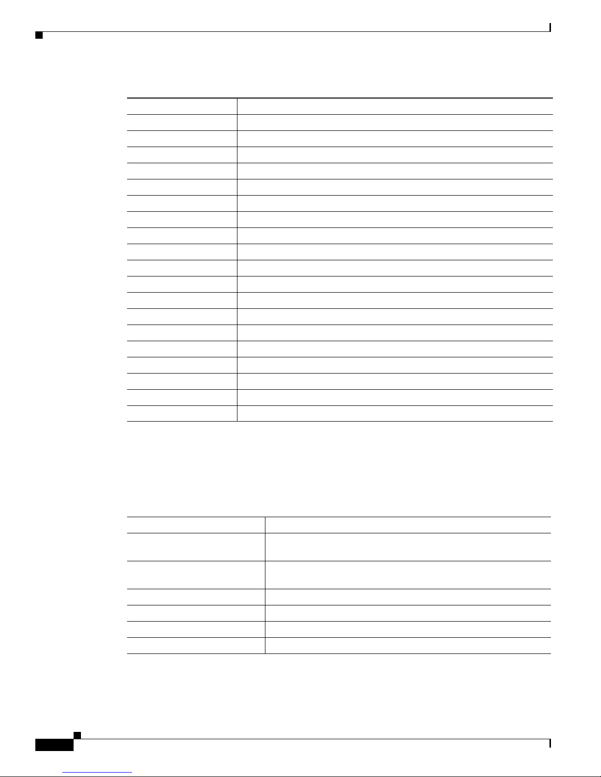
Table 1-1 6 and Table 1 - 17 show the power supply modules available for Catalyst 3750-X and 3560-X
switches and power supply configurations based on switch models.
Table 1-16 Available PoE with AC Power Supply
Switch Models Default Power Supply Available PoE Power
12- and 24-port data (SFP) PWR-C1-350WAC
24-port data
C3KX-PWR-350WAC
–
48-port data
24-port PoE+ PWR-C1-715WAC
48-port PoE+ 462
48-port full PoE+ PWR-C1-1100WAC
24-port UPOE 870
C3KX-PWR-715WAC
1
C3KX-PWR-1100WAC
1
495
847
48-port UPOE 840
1. Japan only: To satisfy regulatory requirements, you must use the CAB-3KX-250VAC-JP power cord with the 1100-W power supply module.
Table 1-17 Available PoE with DC Power Supply
Switch Models Power Supply Available PoE Power
24-port PoE+ 1 220 W
2660 W
48-port PoE+ 1 187 W
2 627 W
24-port UPOE 1 210 W
2650 W
48-port UPOE 1 180 W
2 620 W
OL-19593-03
Catalyst 3750-X and 3560-X Switch Hardware Installation Guide
1-21
Rear Panel Description
Chapter 1 Product Overview
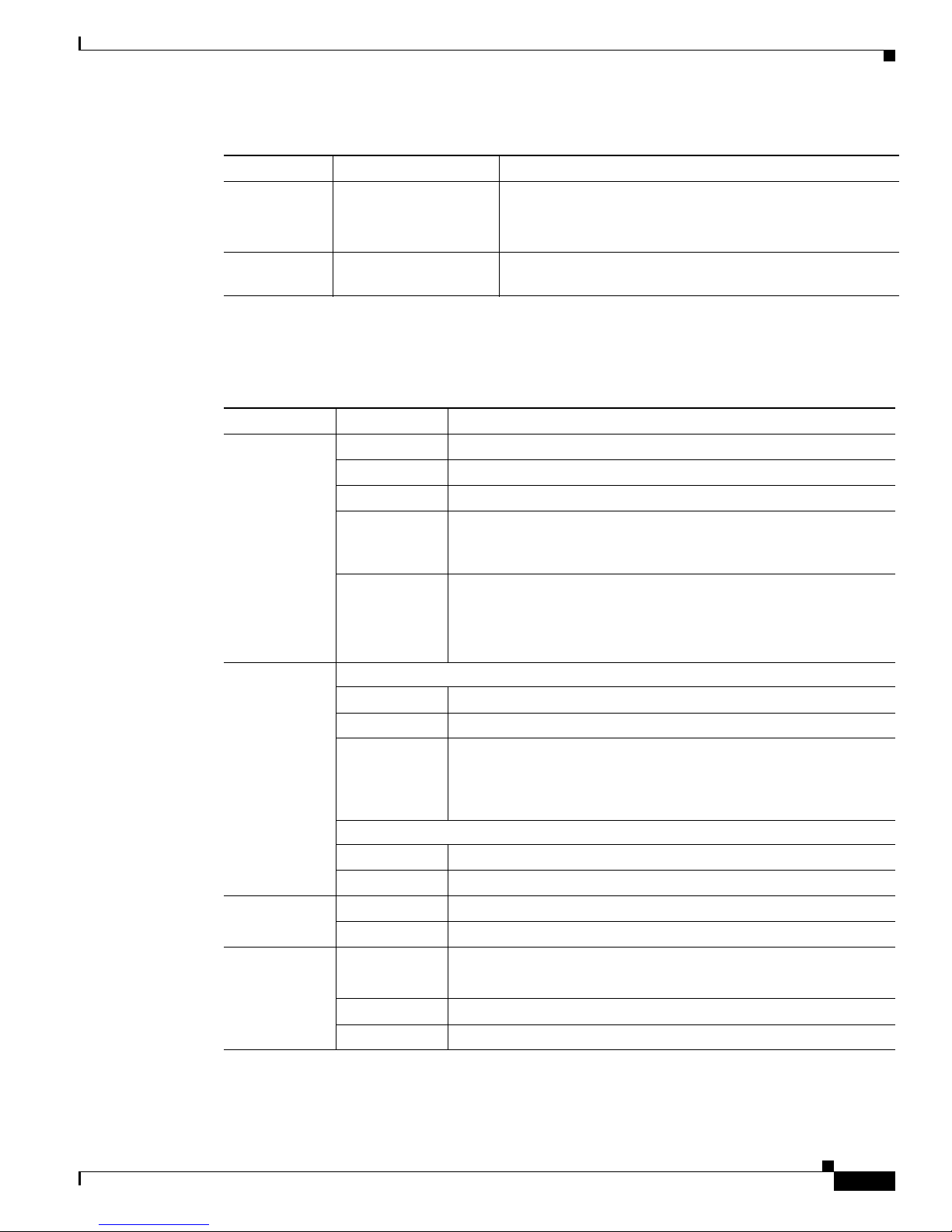
Table 1-18 Switch Power Supply Requirements for PoE, PoE+, and UPOE
PoE Option 24-Port Switch 48-Port Switch
PoE (up to 15.4 W per port) (1) 715-W power supply
(1) 1100-W power supply
(2) 440-W DC power supplies
PoE+ (up to 30 W per port) (1) 1100-W power supply (1) 1100-W power supply plus
(1) 715-W power supply
or
(2) 1100-W power supplies
UPOE (up to 60 W per port) (1) 1100-W power supply plus
(1) 715-W power supply
(2) 1100-W power supplies
(maximum of 30 ports)
or
(2) 1100-W power supplies
Note
A 48-port switch with one 715-W power supply provides up to 8.7 W of PoE to all ports.
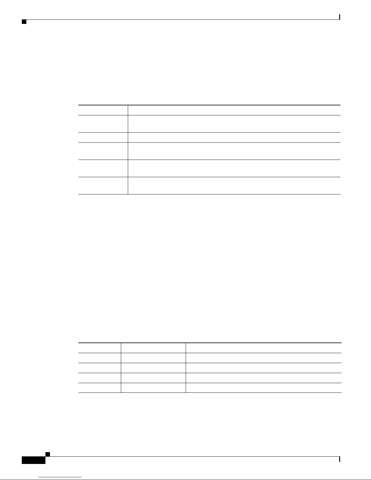
The power supply modules have two status LEDs.
Table 1-19 Switch Power Supply Module LEDs
AC-Power Supply Module LEDs
AC OK Description PS OK Description
Off No AC input power. Off Output is disabled, or input is
outside operating range (AC LED
is off).
Green AC input power present. Green Power output to switch active.
Red Output has failed.
DC-Power Supply Module LEDs
DC OK Description PS OK Description
Off No DC input power. Off Output is disabled, or input is
outside operating range (DC LED
is off).
Green DC input power present. Green Power output to switch active.
Red Output has failed.
For information about replacing a power supply module, wiring a DC power supply module, and module
specifications, see Chapter 3, “Power Supply and Fan Module Installation,” and Appendix A, “Technical
Specifications.”
Catalyst 3750-X and 3560-X Switch Hardware Installation Guide
1-22
OL-19593-03
 Loading...