


KW-128C User's Manual
Video Door Phone Indoor Monitor Video Door Phone Indoor Monitor
Top Way Intelligent Science & Technology Co., Ltd
http://www.kenwei.com

2
CONTENTS
Top Way Technology Top Way Technology
4
17
18
18
18
18
18
18
18
19
20
20
20
20
20
20
20
20
21
21
21
22
22- 24
24- 26
26
27
28
29
30
31- 32
33- 34
35
35
5
5
6
7
7
7
7
7-8
8
8
8
8-9
9
9
9
9-10
10
10
10-11
11
11
12
11-12
12
12
12
12-13
13
14
14
15
15
16
17
PRODUCTION INTRODUCTIONPRODUCTION INTRODUCTION
Time Setting
SD Card Insert
Instruction Of B&W Image Memory(Optional) Instruction Of B&W Image Memory(Optional)
Record Function
Review Function
Auto-off Function
Time Display And Revise Function
Away Function
B&W Image Memory OperationB&W Image Memory Operation
OSD OperationOSD Operation
Image Quality Of Brightness, Contrast And Color Adjustment
Image Effect Setup
Color standard setup
Language Of Image Quality Adjustment Menu Setup
Image size setup
Image quality reset setup
Exit image quality adjustment menu setup
SPECIFICATION AND ACCESSORIESSPECIFICATION AND ACCESSORIES
Dimension
Accessories
INSTALLATIONINSTALLATION
Surface Mount Type Sketch ASurface Mount Type Sketch A
Surface Mount Type Sketch BSurface Mount Type Sketch B
Dismounting methodDismounting method
INSTALLATION ATTENTIONINSTALLATION ATTENTION
WIRING DIAGRAMSWIRING DIAGRAMS
Connection Diagram Of Indoor Unit And Outdoor Camera(1-1)Connection Diagram Of Indoor Unit And Outdoor Camera(1-1)
Connection Diagram Of Indoor Unit And Outdoor Camera(1-2)Connection Diagram Of Indoor Unit And Outdoor Camera(1-2)
Connection Diagram Of Indoor Unit And Outdoor Camera(2-1)Connection Diagram Of Indoor Unit And Outdoor Camera(2-1)
Connection Diagram Of More UnitsConnection Diagram Of More Units
TROUBLE SHOOTING GUIDETROUBLE SHOOTING GUIDE
SPECIFICATIONSSPECIFICATIONS
FEATURES AND PARTSFEATURES AND PARTS
KW-128C Features And PartsKW-128C Features And Parts
KW-137MC Features And Parts(Optional Door Camera)KW-137MC Features And Parts(Optional Door Camera)
OPERATION GUIDEOPERATION GUIDE
The Operation For The Indoor UnitThe Operation For The Indoor Unit
Power On/Off
Call Remind
Talk/Stop
Reject Answering
Open The Door
Monitor/Exit The Monitor
Chord Ring Select
Ring Volume/Talking Volume
No Bother Function
Quit No Bother Function
Intercom(More Than 1 Indoor Unit)
Outdoor unit call transfer(More Than 1 Indoor Unit)
Room Number Indication
Away Function(With Image Memory Function Only)
Exit Away Function(With Image Memory Function Only)
Busy Status
Visitors Call Remind
Alarm For Room Number Confliction(More Than 2 Indoor Units)
Alarm For Communication Confliction(More Than 2 Indoor Units)
Special FunctionsSpecial Functions
Initialization Of Indoor Unit's Number
Indoor unit room number setup-automatically
Indoor unit room number setup-manual(more than 2 indoor units)
LED statusLED status
Voice statusVoice status
Color Image & Video Memory Operatio(Optional)Color Image & Video Memory Operatio(Optional)
Color Image Function
Color Video Function
SD Card Function
3

PRODUCT INTRODUCTION
Thank you for purchasing our products of building intercom system series. Please
read the instructions carefully and follow the directions before install the products.
Any problem regarding to the product, please query your supplier.
GENERAL FEATURES:
Hands-free and auto-off function
Monitor and remote unlock
Kinds of chord ring (optional) and clear tone
Image memory
16:9 screen, widen your vision (for 7" LCD only)
OSD (Brightness/contrast/Color/image size adjustable)
No bother function
B&W or Color image memory (optional)
Colour Image can be recorded in FLASH & SD card (optional)
GENERAL FEATURES:
person if maintenance needed.
Remind users that important operation and maintenance guides are
included in the attached user's manual.
* reserves the right to change or modify design, features,
functions and specifications without any prior notice for the impro-
vement and promotion of products quality.
Remark
4
Top Way TechnologyTop Way Technology
FEATURES AND PARTS
1. 5.6"or 7"color TFT screen
2. LED for power/LED for Image memory
3. LED for door 1
4. LED for door 2
5. Speake
6. TFT OSD navigation(“ ” minus, “ ” plus, “ ” function selection)
7. a.Color Image memory navigation(“ ” up, “ ” down, “ ” confirmation)
b.B&W Image memory navigation(“ ” time; “ ” record, “ ” play)
c.no function without memory
8. Intercom/Music selection
9. Open
Remark
the function after “/” means the button with different functions
under different status.
1
2
3
4
5
6
7
8
9
10
11
12
13
14
15
16
KW-128C Features And PartsKW-128C Features And Parts
CAUTION:Please don't remove cover or back. Please ask professional
5
10. Monitor Door 1/Monitor Door 2/Quit
11. LED of no bother
12. No bother/Volume/Power switch
13. Talk/Stop
14. LED for working status
15. Microphone
16. Slot for SD card(color image memory)

6
Top Way TechnologyTop Way Technology
1. Screws to fix panel
2. CCD camera(B&W/Color)
3. White light/IR light
4. Speaker
5. Room No. and night light
6. Call button
7. Microphone
8. Imbedded assembling box
9. Camera angle adjusting button
1
2
3
4
5
6
7
10
8
9
KW-137MC Features And Parts(Optional Door Camera)KW-137MC Features And Parts Optional Door Camera( )
OPERATION GUIDE
The Operation For The Indoor UnitThe Operation For The Indoor Unit
Remark
The indoor unit is connectable to any outdoor unit with 4-wire from
our company.
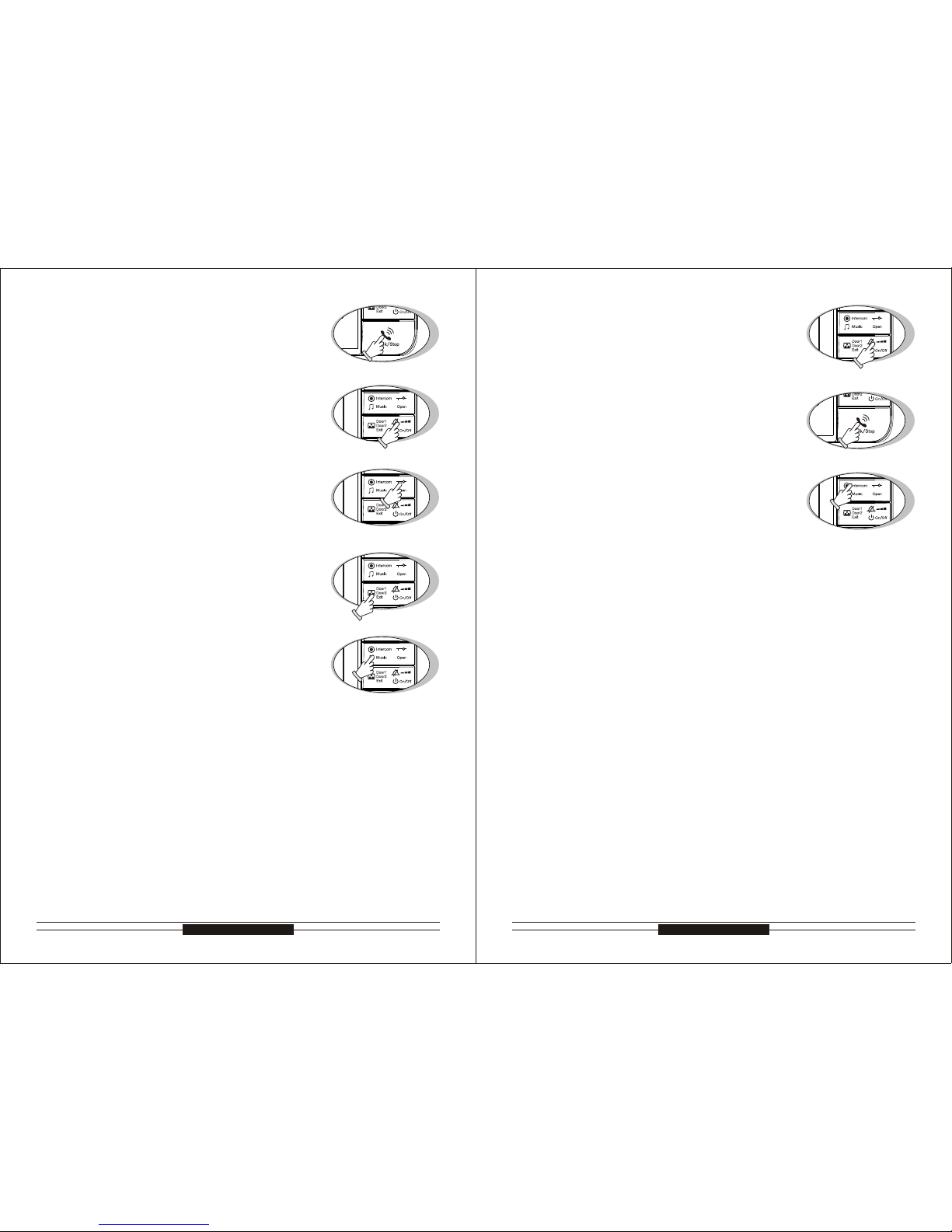
1. Power On/Off
1.1 Power On
On the power, the unit will enter the stand-by status
automatically.
Off the power, press “on” button(Pic. A), the unit will
will light
1.2 Power Off
1. Power On/Off
1.1 Power On
1.2 Power Off
sound “Di” and enter the stand-by status and the LED
Under the stand-by mode, press the “off” button(Pic. A)
for 5 seconds, the unit will sound “Di Di Di” and enter
the power off status and the LED of no bother, power
and working status will turn off.
2. Call Remind
2.1. Outdoor Unit 1 Call The Indoor Unit
2. Call Remind
2.1. Outdoor Unit 1 Call The Indoor Unit
The indoor unit will display the image of outdoor unit 1
Door 1.
2.2 Outdoor unit 2 call the indoor unit(more than 1 outdoor unit)
2.2 Outdoor unit 2 call the indoor unit(more than 1 outdoor unit)
automatically when the outdoor unit 1 calls, and the
LED of outdoor unit 1 will light, the LED of working
status will glitter and the unit will under chord ring se-
ect status(See P8 point 7), the selected melody is for
The indoor unit will display the image of outdoor unit 2
automatically when the outdoor unit 2 calls, and the
LED of outdoor unit 2 will light, the LED of working
status will glitter and the melody for Door 2 is the next
unit will sound “Du Du” when the indoor unit calls
Pic. A
Pic. B
melody of Door 1.
2.3 Indoor unit call indoor unit(more than 1 indoor unit)
The LED of working status will glitter and the indoor
indoor unit. (no ring under no bother status)
3. Talk/Stop
3.1 Call To Talk
When the indoor unit is called, please see “P7 point
tus, the unit and the calling unit can talk.
2.3 Indoor unit call indoor unit(more than 1 indoor unit)
3.1 Call To Talk
3. Talk/Stop
7
2.1”, press “talk” button(Pic. B) to enter talking sta-
10. Connecting port
8
Top Way TechnologyTop Way Technology
3.2 Monitor to Talk
When the indoor unit under “monitor” status, please
3.2 Monitor to Talk
see “P8 point 6”, press “talk” button(Pic. C) to enter
talking status, the indoor unit and the monitored outdoor unit can talk.
8. Ring Volume/talking Volume
8.1 Ring Volume
8. Ring Volume/talking Volume
8.1 Ring Volume
3.3 Stand-by to Talk3.3 Stand-by to Talk
3.4 Stop
3.4 Stop
talk with outdoor unit 1 directly, it is available for the
indoor unit and outdoor unit 1 only.
Enter talk status, repress “stop” button(Pic. C) to fi-
nish talk, the unit will back to stand-by status or will
If you don't want to talk with visitors when they press
be off automatically after 90s.
4. Reject answering4. Reject answering
call button, you can press talk button continually for
will stop automatically.
2 seconds to finish or wait 30 seconds and the ring
a. You can press “open” button(Pic. C) to let visitors in
5. Open the door5. Open the door
when you talk with visitors. (An electronic lock should
be installed on the outdoor)
b. Press “open” button(Pic E), the system will under un-
lock status for 3s, if hold “open” button(Pic E), the
system will always under unlock status, but after 8s,
the system will be back.
F) to monitor the outdoor unit 1, repress “monitor”
6. Monitor/Exit monitor6. Monitor/Exit monitor
“monitor” button again, the unit will exit to monitor
button(Pic. F) to monitor the outdoor unit 2, press
status and back to stand-by status, after 90s. it will
You can choose the chord ring by pressing the
exit the monitor status automatically. (under monitor
“Music” button(Pic. G) for 2 seconds when the unit
is under standby. The ring is different by pressing
“Music” button(Pic. G) each time, you can save the
a. Per press “Volume” button(Pic. H) to adjust ring vo-
lume during selecting chord ring.
b. when this unit calls other indoor units, it will discon-
tinuously sound “Du” and can not adjust the volume
Press the “no bother” button(Pic. H) for 2 seconds
under standby status, the unit will sound “Di” and
can only see the picture of visitors without hearing
enter no bother status and the LED will light. You
the ring while the outdoor unit calls. By pressing the
enter no bother status and the LED will light.
will turn off. Press the “no bother” button(Pic. H) for
2s under ringing status, the unit will stop ringing and
10. Exit no bother function:10. Exit no bother function:
indoor unit enter talking status.
ccessful call from one indoor unit to another indoor
unit.
wer off.
bother” button(Pic. H), it will exit the no bother status when the unit sound “Di”, the LED will turn off.
a. Under stand-by or no bother status, press the “no
b. It will exit no bother function automatically while the
c. It will exit no bother function automatically after su-
d. It will exit no bother function automatically after po-
11. Intercom(more than 1 indoor units)11. Intercom(more than 1 indoor units)
a. Under standby status, press “Intercom” button(Pic.
J) and then “talk” button(Pic. I), you can cal an-
other indoor unit. (Remark: It's available for two in-
Pic.D
Pic.H
Pic.J
Pic.E
Pic.F
Pic.G
Pic.C
Pic.I
“talk” button(Pic. I) to talk with visitor and the LED
status, there is no voice, cannot open the door)
or wait for the ring stop automatically. The select-
ring you prefer with pressing “talk” button(Pic. C)
ed melody is for Door 1. The melody for Door 2 is
continuously sound “Du”.
the next melody. The music from intercom will dis-
9
7. Chord ring select7. Chord ring select
8.2. Talking Volume8.2. Talking Volume
Press “Volume” button(Pic. H) to adjust talking vo lume during talking status.
9. No bother function9. No bother function
Under stand-by status, press “monitor” button(Pic.
Under stand-by status, press “talk” button(Pic.C) to

10
Top Way TechnologyTop Way Technology
b. When there are more than two indoor units, the times
to No.3 extension, press “intercom” button(Pic.K) 3 ti-
mes and then press “talk” button(Pic. L)
return to normal when talk is finished.
you press the “Intercom” button(Pic.K) should be the
same as the room No. of called room, and then press
the “talk” button(Pic. L) to talk.(e.g. If you want to talk
During the operation of a and b, the related buttons
should be pressed within 4 seconds. If fail to press “Intercom” button (Pic. K) or “talk” button (Pic. L), or wrong
button pressed, the intercom function should be operated from very beginning.
c. When the indoor units ring, only the “talk” button(Pic. L)
of called unit can be pressed to talk and under this status, the no bother LED light. The no bother function will
d. During calling and ringing from the indoor units, the
two ringing units can by pressing “talk” button(Pic. L)
to end of the calling.
12. Outdoor unit call transfer(more than 1 indoor unit)
12. Outdoor unit call transfer(more than 1 indoor unit)
During the talk, the way to transfer the call from out-
tercom between indoor ones. After the successful tran-
busy status.
13. Room Number indication
13. Room Number indication
door unit to another indoor unit is the same as the in-
sfer, the called indoor unit will ring and others will be in
Under the stand-by status, press “talk” button(Pic. L)
standby light is in accordance with the room number.
while the LED flashing and the flashing times of the
Release “Talk” button(Pic. L), the unit will go back to
unit of No.2)
14. Away function(with image memory function only)
14. Away function(with image memory function only)
stand-by status. (eg: flashing twice stands for the sub
15. Exit away function(with image memory function only)
15. Exit away function(with image memory function only)
a. With color memory: under stand-by status, the away
function will be turned on by pressing “monitor” button
it automatically.
(Pic. M) for 2s,the unit will sound “Di Di” and the LED
will light continually . The unit will with the away func-
calls, the unit will store the image from the outdoor un-
tion when it turns on per time. While the outdoor unit
b. With B&W memory: under stand-by status, the away
function will be turned on by pressing “monitor” bu-
unit will exit the away function when the power is
tton(Pic.N) for 2s, the unit will sound “Di” and the
a. With color memory: under stand-by and away func-
outdoor unit automatically.
off. The away function will be turn off when the unit
turns on per time.
16. Busy status(more than 1 indoor units)
16. Busy status(more than 1 indoor units)
tion status, will exit the away function by pressing
“monitor” button(Pic. N) for 2s, the unit will sound
“Di” and the LED will flash. While the outdoor unit
calls, the unit will cancel to store the image from the
b. With B&W memory: under stand-by and away func-
tion status, will exit the away function by pressing
“monitor” button(Pic. N) for 2s, the unit will sound
“Di” and the LED of stay away(blue light) will turn
With color memory: the functions of color image me-
mory, chord ring select and ring volume adjustment
tus, but for other functions, the unit will sound “Du”.
functions, the unit will sound “Du”.
door units will enter busy status.
with any outdoor units, the indoor unit with outdoor
camera assist this indoor unit enter monitoring and
light and other indoor units will enter busy status.
standby mode.
are working properly while the units under busy sta-
With or without memory: the functions of chord ring
select and ring volume adjustment are working properly while the units under busy status, but for other
a. When the indoor unit with outdoor camera is in mo-
nitoring and talking with any outdoor unit, other in-
b. When the indoor units enter busy status and talking
talking with outdoor unit status and supply the power to this outdoor unit, the LED of outdoor unit will
c. When the two indoor units are communicating, other
ones will be in busy status. After the communication,
the busy status finishes and all indoor units enter
Pic.L
Pic.M
Pic.N
Pic.K
door units only.)
11
off or the power is cut off
LED of away(blue light) will light continually. The

12
Top Way TechnologyTop Way Technology
17.Visitors call remind(more than 1 indoor units)
17.Visitors call remind(more than 1 indoor units)
calls.
b. When the indoor unit is talking with outdoor unit, an-
other outdoor unit calls in, the indoor unit in commu-
a. When the indoor unit under stand-by, monitoring, call-
ing, talking and without no-bother status, the indoor
unit and outdoor unit will ring while the outdoor unit
nication will sound “Di Di Di” discontinuously to remind
18. Alarm for room number confliction(more than 2 indoor units)
18. Alarm for room number confliction(more than 2 indoor units)
that there is another visitor call. At this time the indoor
When the room number of indoor unit is the same as
confliction.
19. Alarm for communication confliction(more than 2 indoor units)
19. Alarm for communication confliction(more than 2 indoor units)
and outdoor ones will not ring.
that of the others, the unit will sound discontinuous
“Di”, and then you need to change this number to avoid
When the indoor unit sounds “Di” every three seconds,
it shows the connection between the indoor and outdoor unit has communication confliction. Please inspect the circuitry or check the indoor monitor if in off
(Pic. Q) to connect with the outdoor, it quit the alarm
automatically.
Special FunctionsSpecial Functions
If the system is working properly, don't set the room no.Improper setup will make the f the system is working properly, don t set the room no.Improper setup will make the
system in trouble.
system in trouble.
When all indoor units and outdoor camera are install-
ed, the system doesn't work properly please reinitialize all indoor units and setup the room numubers.
Turn off the unit, press “Intercom” button at the same
time press “on/off” (Pic. R) to turn on the unit.The system will sound “Di”, and release “Intercom” button.
Now the “Talk” LED flashes three times quickly then
back to standby.The initialization finish, room No.is 0.
2.Indoor unit room number setup-automatically(more than 2 indoor unit)
2.Indoor unit room number setup-automatically more than 2 indoor unit
a.When there are 2 indoor units,after initialzation of all
indoor units(see point 1) , press “call” from outdoor ca-
mera and the indoor units will ring.The unit's room
b.When there are more than 2 indoor units, after initia
main indoor unit and no.2 indoor unit and turn them
on, press “call” from outdoor camera and the indoor
lization of all indoor units(see point 1), connect the
units will ring.And then connect no.3 indoor unit and
call from outdoor unit.When the indoor units ring,
the no.3 indoor unit is set.No.4, No.5, etc.
3.Indoor unit room number setup-manual(more than 2 indoor unit)
3.Indoor unit room number setup-manual more than 2 indoor unit)
will allocate the room number automatically. If you
want to change the room number (Except the indoor
one which is connected to the outdoor unit), it can
When there are more than 2 indoor units, the system
a. Please make the unit under power off status.
be changed following bellowing steps:
b. After the first step, press and hold “intercom” button
(Pic. S) at the same time press “on/off” button(Pic.
S1), when the unit sounds “Di”, release “intercom”
button and “on/off” button.Then press “Open” button
(Pic.S3) three times within 4 seconds. At this time
working LED will glitter three times and the unit sound
which stands for the room number.
is successfully completed.
ful change and then turn on again.
“Talk” button(Pic.S2), the unit will sound “Di” and
c. Following the second step, each time you press
please check the flash times of the working LED
d. After room number setting, press “on/off” button(Pic.
S2) for 2s, the unit will sound “Di”, and the working
LED glitter three times and the room number setting
e. After the room number setting, if the number is the
same as the others in this system, the unit will alarm
and sound “Di” discontinuously. You can reset the
room number or change the conflicted one. Cut off
the power supply of the alarming unit after success-
Remark
During step b of point 3, if you fail to press “Open” button three times
The operation failed, you have to restart from step a.
within 4 seconds, the working LED will return to glitter under standby.
Pic.S
Pic.S1
Pic.R
Pic.O
Pic.P
Pic.Q
Pic.S4
Pic.S3
Pic.S2
“Di” and the no bother LED will light up.
numbers are set automatically and ready to work.
13
status. Press “monitor” button(Pic. P) or “talk” button
1.Initialization of indoor unit's number1.Initialization of indoor unit s number
14
Top Way TechnologyTop Way Technology
LED StatusLED Status
Color Image & video memory operation(Optional) Color Image & video memory operation(Optional)
Voice statusVoice status
Power LED light
Power on
LED of outdoor unit 1 and the LED of working status light
monitoring and talking with outdoor unit 1
LED of outdoor unit 2 and the LED of working status light
monitoring and talking outdoor unit 2
No bother LED and the LED of working status light
talking with indoor unit
LED of outdoor unit 1 light and the LED of working status glitter
calling from the outdoor unit 1
LED of outdoor unit 2 light and the LED of working status glitter
calling from the outdoor unit 2
The working status of LED glitter
calling from other indoor units
No-bother LED light continually
under no-bother status
Power LED glitter
The unit turns off the away function (with color memory)
LED of B&W memory light
under the away status (with B&W memory)
Power LED light
LED of outdoor unit 1 and the LED of working status light
LED of outdoor unit 2 and the LED of working status light
No bother LED and the LED of working status light
LED of outdoor unit 1 light and the LED of working status glitter
LED of outdoor unit 2 light and the LED of working status glitter
The working status of LED glitter
No-bother LED light continually
Power LED glitter
LED of B&W memory light
Sound “Di” discontinuously: room number confliction
Sound “Di Di” discontinuously: communication confliction
Sound “Di Di Di” discontinuously: calling from another outdoor unit
sound “Du” : Operation is not allowed
Sound “Di-----------” : Power on
Sound “Di” discontinuously:
Sound “Di Di” discontinuously:
Sound “Di Di Di” discontinuously:
sound “Du” :
Sound “Di-----------” :
Remark
indoor unit and outdoor unit connected well, call the indoor
indoor unit, do not change the indoor unit any more.
All the indoor units and outdoor units are formatted in our
factory. Any indoor unit can connect any outdoor unit. When
unit from the outdoor unit first to let the system identify the
correct connection and start work. Otherwise, they system
will not work properly. After the outdoor camera calls the
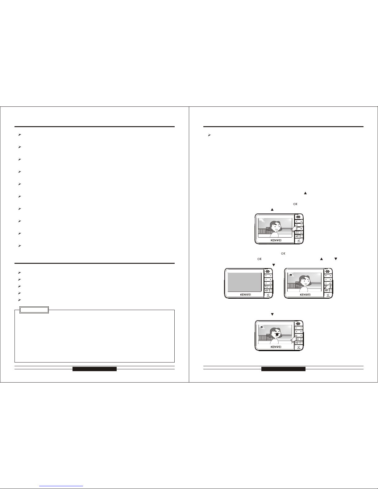
Color image function
1. This indoor monitor is equipped with storing and recalling color image
functions.Even after power off, the image will be still stored.
2. Store color images:
a. This unit is set with storing color function. This is a default function.
b. Auto storing
c. Manual storing
time.
When talking with outdoor camera, press “ ” , after 5 seconds, when the
screen displays clock, press “ ” to store a color image with time.
3.View color images
a. When in standby status, press the “ ” button for 5 seconds, when the screen
b. When viewing images, press “ ” to exit.
4.Delete color images
When viewing images, press “ ” for 3 seconds to delete the image.
Color image function
1. This indoor monitor is equipped with storing and recalling color image
functions.Even after power off, the image will be still stored.
2. Store color images:
3.View color images
4.Delete color images
When a visitor calls in, it will store a color picture automatically. The picture is
with time.
When a visitor calls in, after 5 seconds, press “ ” to store a color image with
Off
On
2007/ 11/16
15:1 9:06
Off
On
2007/ 11/16
15:1 9:06
Off
On
2007/ 11/16
15:1 9:06
106/ 106
Pic. A-2 Pic. A-3
Pic. A-1
2007/ 11/16
15:1 9:06
Off
On
001/ 106
Pic. A-4
15
displays clock, press “ ” again to view images. Press “ ” or “ ” to scroll.

16
Top Way TechnologyTop Way Technology
Note: information of the picture and fileNote: information of the picture and file
Storage format
Image size
Video size
Image quantity
Video quantity
Image: jpg; Video: avi, 5fps
About 60K (depending on the background)
About 500K (depending on the background)
Without SD card: about 20 segments
Maximum SD card capacity: 2G
Maximum video: 1024 segments
Without SD card: about 200 pieces
Maximum SD card capacity: 2G
Maximum image: 1024 pieces
Color video function
Color video function
Off
On
2007/ 11/16
15:1 9:06
2007/ 11/16
15:1 9:06
Off
On
REC
Pic. A-5
Pic. A-6
Off
On
2007/ 11/16
15:1 9:06
021/ 106
Off
On
2007/ 11/16
15:1 9:06
021/ 106
Pic. A-7 Pic. A-8
or “ ” to select the setting menu, press “ ” to enter the setting.
firm and change to next item. After finish, it will exit time setting automatically.
Format built-in memory and SD card
Format built-in memory and SD card
2007/ 11/16
15:1 9:06
Off
On
021/ 106
Pic. A-9
1. This indoor monitor is equipped with recording and playing color video 1. This indoor monitor is equipped with recording and playing color video
functions. Every time 10 seconds with avi format. Even after power off,
the video will be still stored.
2. Record color video
functions. Every time 10 seconds with avi format. Even after power off,
the video will be still stored.
2. Record color video
When a visitor calls in, after 5 seconds of the monitor working, press “ ” to re-
cord color video.
displays clock, press “ ” to record color video.
3. Play color video
3. Play color video
When talking with outdoor camera, press “ ” , after 5 seconds, when the screen
a. When in standby status, press “ ” button for 5 seconds, when the screen displays
displays “ ” , it is a video. At this time press “ ” to play the recorded video.
b. When playing video, press “ ” for 3 seconds to exit.
4. Delete color video
When playing video, press “ ” for 3 seconds to delete the video.
SD card function
SD card function
1. This indoor monitor is equipped with SD card function to store images and videos.
The SD card can be taken out to input to computer.
automatically.
2. If SD card not inserted, the images and videos will be saved in the built-in me-
mory; if SD card inserted, the images and videos will be saved in the SD card
2. During time setting, press “ ” or “ ” to change the date and time, press “ ” to con-
Off
On
Time s etup
2
6
Off
On
Off
On
For mat
2
6
Pic. B-3
Pic. B-4
Pic. B-5
Off
On
2
6
2007/ 01/01
Pic. B-1
Pic. B-2
Off
On
Time s etup
2
6
clock, press “ ” again to view video. Press “ ” or “ ” to scroll, when the screen
1. When in standby status, press “ ” or “ ” for 5 seconds, when the screen displays
Time settingTime setting
clock, press “ ” for 3 to 4 seconds, the menu for setting time will display. Press “ ”
When in standby status, press “ ” or “ ” for 5 seconds, when the screen displays
clock, press “ ” for 3 to 4 seconds, the menu for setting time will display. Press “ ”
card.
17
or “ ” to select the format menu,press “ ” to format the built-in memory and SD

Off
On
1. Recording function:
1. Recording function:
SD card insert: Press the card slightly into the slot as the arrow direction.
SD card take out: Press slightly at the card, it will come out from the slot.
SD card insert:
SD card take out:
The system will auto record each visitor's image under "AWAY" mode.
Push " " to enter into the record mode,
push one time record one picture with
time.
Enlarge the picture
1. If the system enters away management function,when a visitor presses Call button
15t h Mar 200 6 10:03 1 -115t h Mar 200 6 10:03 1 -1
15t h Mar 200 6 15:21 3 -115t h Mar 200 6 15:21 3 -1
15t h Mar 200 6 13:54 2 -115t h Mar 200 6 13:54 2 -1
25 th M a y 20 06 1 4 :3 8 4- 125 th M a y 20 06 1 4 :3 8 4- 1
25th M ay 2006 14:37 3 -125th M ay 2006 14:37 3 -1
25th M ay 2006 1 4:38 4- 125th M ay 2006 1 4:38 4- 1
25th M ay 2006 14:35 1 -125th M ay 2006 14:35 1 -1 25th M ay 2006 14:36 2 -125th M ay 2006 14:36 2 -1
18
Top Way TechnologyTop Way Technology
SD card insertSD card insert
B&W Image Memory OperationB&W Image Memory Operation
Instruction Of B&W Image Memory(Optional) Instruction Of B&W Image Memory (Optional)
During operation of image memory unit, the time will display and the time and date
are editable.
from the outdoor camera, the indoor unit will store the visitor's picture. When you
every time. After 10 seconds, the system will go back to monitor status.
come back home, you can review the visitor's picture by pressing “ ” button.
display by pressing “ ” button every time. (Up to 32 or 64 pictures, when more
than 32 or 64 pictures the earliest pictures will be over written).
2. When in monitor status, press “ ” to store image. Store 1 picture with time
to exit time setting.
4. In monitor status, press “ ” button to display time and date, and press “ ”
3. In monitor status, review 1 picture in time sequence by pressing “ ” button
19
button to edit time and date. When time adjustment finishes, press “ ” button
3. Auto-off function:
-3. Auto off function:
The user can store visitor's picture with time display. (Up to 32 or 64 pictures).
2. Picture review function:
2. Picture review function:
The user can review stored pictures during monitor and talking status.
After 10 seconds of operation of reviewing pictures, the system will return to standby
status automatically.
4. Time display and edit function:
4. Time display and edit function:
5. Away management function:
5. Away management function:
When in Away function, the indoor unit will store the visitor's pictures automatically.

50
50
50
MANUAL
Off
On
ADJ
BRIGHTNESS
CONTRAST
COLOR
IMPACT
EXIT
SEC
Menu A
OSD operationOSD operation
“ ” button, the window will display the second image quality adjustment menu B.
1. Image quality of brightness, contrast and color adjustment
Press “ ” button, the window will display the image quality adjustment menu A while TFT is
working, press “ ” button to select brightness, contrast and color, press “ ” to weakening,
press “ ” to enhancing.
2. Image quality setup
Press “ ” button, the window will display the image quality adjustment menu A while TFT is
working, press “ ” button to choose image quality setup, then press “ ” and “ ” button to
adjust in bright, soft, standard and personal settings.
3. Color standard setup
Press “ ” button, the window will display the image quality adjustment menu B while TFT is
working, then press “ ” and “ ” button to adjust in AUTO, SECAM , NTSC and PAL.
4. Language of image quality adjustment menu setup
Press “ ” button, the window will display the image quality adjustment menu B while TFT is
working, then press “ ” and “ ” button to choose the language you need.
5. Image size setup
Press “ ” button, the window will display the image quality adjustment menu B while TFT is
in 16:9 and 4:3
6. Image quality reset
Press “ ” button, the window will display the image quality adjustment menu B while TFT is
will come back to default status.
7. Exit Image quality adjustment menu
Press “ ” button, the window will display the image quality adjustment menu B while TFT is
1. Image quality of brightness, contrast and color adjustment
2. Image quality setup
3. Color standard setup
4. Language of image quality adjustment menu setup
5. Image size setup
6. Image quality reset
7. Exit Image quality adjustment menu
20
Top Way TechnologyTop Way Technology
Menu B
Off
On
COLOR SYS
LANGUAGE
SCALER
RESET
EXIT
SEC
ADJ
AUTO
ENGLISH
16:9
Product dimension:
SPECIFICATIONS AND ACCESSORIES
Accessories:
Dilatant Plug
Mounting Screw: 4×25
Short Circuit Connector
DC adaptor
13.5V/1.5A
29
222.5
137
working, press “ ” button to choose the image size, then press “ ” and “ ” button to select
working, press “ ” button to choose exit, then press “ ” and “ ” button to exit.
working, press “ ” button to choose reset, then press “ ” and “ ” button, the image quality
(Unit:MM)
21
Brightness, contrast, color, image size and language are adjustable. Press “ ” button the
window will display the image quality adjustment menu A while TFT is working, press “ ” bu-
tton to choose the one which you want to adjust, after choosing the exit menu A, to repress

INSTALLATION
86 Box
225
106
13.6
72
85
40
12.5
Surface Mount Type Sketch ASurface Mount Type Sketch A
(Unit:MM)
1
Connect the line with the line through the mounting bracket in
bracket tightly, and keep them on the line. Noted: Each port in
one line, please check it one by one after connection
After connection, insert the wiring ports to the needles.
3
2
22
Top Way TechnologyTop Way Technology
according the bracket hole, and then drill the dilatant plug in it.
Make sure the connection place of the mounting bracket aim
correct place, make the bracket aimed at the hole, screw the
23
at the hole in the wall or the wall box, drill 4 holes on the wall

24
Top Way TechnologyTop Way Technology
After inserting, tidy up the wires and cover the box.
Buckle the unit into the bracket.
4
5
86 Box
225
106
13.6
72
85
40
12.5
Surface Mount Type Sketch BSurface Mount Type Sketch B
(Unit:MM)
25
1
according the bracket hole, and then drill the dilatant plug in it.
Make sure the connection place of the mounting bracket aim
at the hole in the wall or the wall box, drill 4 holes on the wall

INSTALLATION ATTENTION
Remark
attention to:
Keep sufficient space to adjust while installing.
Not put hot resource under the unit.
shall be easily accessible.
When you choose the place to install the unit, please pay
Keep sufficient space for ventilation and easy communication.
The socket outlet shall be installed near the equipment and
Connect the line with the line through the bracket in correct place,
make the bracket aimed at the hole, screw the bracket tightly, tidy
up the line. Buckle the unit into the bracket.
you can press the edge of
the mounting bracket, and
then pull forward the unit.
2
26
Top Way TechnologyTop Way Technology
Use a screw driver to take out
the connecting ports.
Dismounting methodDismounting method
out of the mounting bracket,
If you want to put the unit
27
1. Do not expose the unit to sunshine or rain:
Even if you do not use it, don't expose it to sunshine or rain.
2. Do not expose to intense light:
Spotlight may cause stain or striation in the screen.
3. Do not disassemble the unit by yourself:
Improper disassembly may damage the unit or cause electric shock.
4. Do not splash water on the unit:
Install the unit in dry place. In case that the unit gets wet, turn off the unit and contact
your dealer.
5. Check the ambient temperature and humidity:
1. Do not expose the unit to sunshine or rain:
2. Do not expose to intense light:
3. Do not disassemble the unit by yourself:
4. Do not splash water on the unit:
5. Check the ambient temperature and humidity:
Avoid using the unit where the temperature is hotter or colder than specified, other-
temperature and humidity.
6. In case of trouble:
If any trouble occurs while you are using the unit, turn off the power and contact
your dealer to avoid worse problem or unpredictable accident.
7. About operation:
speaker. If the unit will not be used for a long time, please switch it off.
8. About clean:
wise the internal parts may get affected. Special care is required to use the unit at high
Keep the unit away from magnetic equipments such as microwave oven or big
Use soft cloth to clean the unit. Do not use any impregnant, such as alcohol, benzene. If you have any problem, please contact your dealer.

POWER
POWER
RVV4*0.5
RVV1*0.5
RVV1*0.5
RVV1*0.5
RVV1*0.5
RVV1*0.5
RVV1*0.5
RVV4*0.5
1
2
3
4
5
6
7
8
9
10
11
12
13
14
15
16
+V
C
C
-
GND
AF
AF
AF
D
GN
GND
G
D
N
VCC
CVC
DAT
VD
VD
VD
PO
W
ER
D
O
OR2
DOR1
O
S
H
O
R
T
EXT
EN
IO
N
-I
/O
S
1
1
1
1
2
2
2
2
I/O
I/O
I/O
I/O
1.
VDC35
13.5V/1.5A
5
6
7
8
9
10
11
12
13
14
15
16
+VCC
-GND
Connection Diagram Of Indoor Units And Outdoor Camera(1-2)Connection Diagram Of Indoor Units And Outdoor Camera 1-2
Electronic Lock
Electronic Lock
Electronic Lock
Outdoor Camera(2)
Outdoor Camera(1)
Outdoor Camera
Outdoor Camera(2)
Outdoor Camera(1)
Short circuit connector
(need to insert this connector on single
unit or last extension unit)
Short circuit connector
(need to insert this connector on single unit or last extension unit)
Lock Electric Power
Lock Electric Power
Lock Electric Power
Electronic
Lock
Electronic
Lock
Electronic
Lock
Lock Electric
Power
Lock Electric
Power
Lock Electric
Power
Connection Diagram
Connection Diagram
1
2
3
4
5
6
7
8
9
10
11
12
13
14
15
16
C
+
VC
-GD
N
AF
AF
AF
GND
G
D
N
D
GN
V
C
C
VCC
D
T
A
VD
VD
VD
OWE
PR
DO
R
2O
DOO
R1
SR
HO
T
TN ON
EX
E
S
I
-
I/
O
1
1
1
1
2
2
2
2
I/O
I/O
I/O
I/O
DC13.5V
POWER
RVV4*0.5
RVV1*0.5
RVV1*0.5
RVV1*0.5
1
2
3
4
5
6
7
8
9
10
11
12
13
14
15
16
+VCC
-GND
AF
AF
AF
GND
GND
GND
VCC
VCC
DAT
VD
VD
VD
POWER
DOOR2
DOOR1 SHORT
EXTENSION-I/O
1
1
1
1
2
2
2
2
I/O
I/O
I/O
I/O
DC13.5V
13.5V/1.5A
5
6
7
8
9
10
11
12
13
14
15
16
+VCC
-GND
WIRING DIAGRAMS
Connection Diagram Of Indoor Units And Outdoor Camera(1-1)Connection Diagram Of Indoor Units And Outdoor Camera 1-1
28
Top Way TechnologyTop Way Technology
29

Connection Diagram Of Indoor Units And Outdoor Camera(2-1)Connection Diagram Of Indoor Units And Outdoor Camera 2-1
POWER
RVV4*0.5
RVV4*0.5
RVV1*0.5
RVV1*0.5
RVV1*0.5
13.5V/1.5A
13.5V/1.5A
1 2 3 4
1
2
3
4
5
6
7
8
9
10
11
12
13
14
15
16
1
2
3
4
5
6
7
8
9
10
11
12
13
14
15
16
1
2
3
4
5
6
7
8
9
10
11
12
13
14
15
16
+VCC
-GND
AF
AF
AF
GND
GND
GND
VCC
VCC
DAT
VD
VD
VD
POWER
DOOR2
DOOR1 SHORT
EXTENSION-I/O
1
1
1
1
2
2
2
2
I/O
I/O
I/O
I/O
DC13.5V
KW-128C(Main Indoor Unit)
KW-128C
Main Indoor Unit
KW-128C(Extension)
KW-128C
Extension
Electronic Lock
Lock Electric Power
Outdoor Camera
Outdoor Camera
Lock Electric
Power
Electronic Lock
Short circuit connector
(need to insert this connector on single unit or last extension unit)
30
Top Way TechnologyTop Way Technology
31

Lock Electric Power Lock Electric Power
KW-128C
Main Indoor Unit
KW-128C(Main Indoor Unit)
KW-128C(Extension 1)
KW-128C
Extension 1
KW-128C
Extension N≤3
KW-128C(Extension N≤3)
Outdoor Camera(1)
Outdoor Camera(1) Outdoor Camera(2)
Outdoor Camera(2)
Electronic Lock Electronic Lock
Lock Electric
Power
Lock Electric
Power
Short circuit connector
(need to insert this connector on single unit or last extension unit)
13.5V/1.5A
13.5V/1.5A
13.5V/1.5A
1122334
4
1
2
3
4
5
6
7
8
9
10
11
12
13
14
15
16
1
2
3
4
5
6
7
8
9
10
11
12
13
14
15
16
1
2
3
4
5
6
7
8
9
10
11
12
13
14
15
16
1
2
3
4
5
6
7
8
9
10
11
12
13
14
15
16
+VCC
-GND
AF
AF
AF
GND
GND
GND
VCC
VCC
DAT
VD
VD
VD
POWER
DOOR2
DOOR1 SHORT
EXTENSION-I/O
1
1
1
1
2
2
2
2
I/O
I/O
I/O
I/O
DC13.5V
32
Top Way TechnologyTop Way Technology
RVV4*0.5
RVV4*0.5
RVV4*0.5
RVV1*0.5
RVV1*0.5
RVV1*0.5
RVV1*0.5
RVV1*0.5
RVV1*0.5
POWER
POWER
RVV4*0.5
Connection Diagram Of More UnitsConnection Diagram Of More Units
Electronic Lock
Electronic Lock
33

35
34
Top Way TechnologyTop Way Technology
SPECIFICATIONSTROUBLE SHOOTING GUIDE
KW-128C
5.6"/7"Color TFT(optional)
Consumption
13.5V/1.5A
Model
Item
Display
Power
Wiring
Ring
Communication
Wiring Distance
Operation
Temperature
Outdoor Unit
4 wires in polarity
Music,Chord and “DingDong”
Hands free
8.8W(with color image memory) 13.5V/650mA
6.75W(with B&W image memory) DC13.5V/500mA
6.1W(without image memory function) DC13.5V/450mA
50M/165Inch(RVV4*0.5)
-20 C~+50 C
。 。
Connectable to any outdoor camera from our company
Problem
Possible Cause
Resolving
all
The power LED doesn't
work
The unit doesn't supply
the power
The power is off
Cannot call
circuit
The unit is in off state
camera
of the monitor
or not
od of the indoor unit
the No.1 operation me-
Exit the off state refer on
thod of the indoor unit
Check the connection
unit
Exit the off state refers on
No.1 of operation me-
The unit is in off
are shorted
The wires between the
monitor and the camera
Two room number is the
same
mera
connection in door ca-
Check the connection
Reset the room number
refers on No. 3 of special
ber
mera
Exit the off state refers on
No.1 of operation me-
Check the connection
the unit
thod of the indoor unit
between the door and
Reset the room number
ber
The last monitor's short
circuit Connector is not
inserted
Can call well but the picture is overlapped
line well
Cannot monitor the door
“Di” of the monitor
Discontinuous music in
Continuous music “Di”
The unit doesn't work at
The AF line is in short
Room number is not set
Some problems of the
Check the adapter is ok
between the door and the
refers on No. 3 of special
function of setting num-
function of setting num-
problem of the door ca-
Insert the short circuit
 Loading...