


AI296
TM
16-Port High Speed Multi-Protocol Line Card
User’s Guide
Version 9.8x
Part Number 296UM Rev 5
© 2008 by Kentrox, Inc. All rights reserved.

Copyright © 2008 by Kentrox, Inc. All Rights Reserved. The ma terial discussed in this publication
is the proprietary property of Kentrox, Inc. Kentrox retains all rights to reproduction and
distribution of this publication.
Kentrox is a registered trademark of Kentrox, Inc. Applied Innovation, Applied Innovation Inc., the
AI logo, and other names are the intellectual property of Kentrox. All other product names are
trademarks or registered trademarks of their respective owners.
Information published here is current as of this document’s date of publication, but is subject to
change without notice. You may verify product information by contacting our headquarters in
Oregon. Kentrox is an Equal Opportunity/Affirmative Action employer.
Kentrox, Inc.
5800 Innovation Dr.
Dublin, Ohio USA 43016-3271
Toll Free: (800) 247-9482
International: +1 (614) 798-2000
Fax: +1 (614) 798-1770
15201 NW Greenbrier Pkwy.
Suite C6
Beaverton, Oregon USA 97006
Toll Free: (800) 733-5511
Direct: (503) 643-1681

About this Document
This document explains how to install, configure, and operate the AI296 16-port high speed
multi-protocol line card.
You should have a working knowledge of the following:
z Your network
z AISwitch
z X.25 protocol
z Asynchronous protocols
z TCP/IP
z PC or asynchronous terminal configuration
TM
technology
i

AI296 Version 9.8x User’s Guide
About this Document: Document Conventions
Document Conventions
Table 1 describes the text conventions used in this document.
Convention Meaning
Table 1 Document Conventions
Screen Text, Menu Items,
System Prompts, Messages
and Reports
Static Command Text
This style indicates Kentrox configuration screen text,
menu items, system prompts, messages, and reports.
In a command statement, this style indicates text that
should be entered exactly as shown at a command line.
Variable Command Text
In a command statement, this style indicates
user-specified text.
...
In a command statement, ellipses (...) signify that the
preceding parameter can be repeated a number of
times.
[ ]
[ | ]
In a command statement, square brackets indicate an
optional parameter. Two or more parameters in square
brackets with a vertical bar ( | ) between them indicate a
choice of optional parameters.
{ | }
In a command statement, two or more parameters in
braces with a vertical bar ( | ) between them indicate a
choice of required parameters.
Variable Field Text This style indicates variable information you type in a
dialog box field.
KEYS Uppercase body text indicates keys on a keyboard,
such as the TAB or ENTER keys. Keys used in
combination are connected with a plus symbol (+).
Labels This style designates physical components on Kentrox
products such as jumpers, switches, and cable
connectors.
Note messages emphasize or supplement important
Note:
points of the main text.
Important: Important messages provide information that is
essential to the completion of a task.
Tip messages provide information that assists users in
Tip:
ii
operating equipment more effectively.
Table 1 Document Conventions (Continued)
Convention Meaning
Caution messages indicate that failure to take a
CAUTION:
specified action could result in loss of data and/or harm
to the software or hardware.
Warning messages indicate that failure to take a
WARNING:
specified action could result in physical harm to the
user.
AI296 Version 9.8x User’s Guide
About this Document: Document Conventions
iii

AI296 Version 9.8x User’s Guide
ENSURE PROPER COOLING
About this Document: Cautions and Warnings
Cautions and Warnings
Electrostatic Discharge Caution
CAUTION: Kentrox equipment and its peripherals contain electrostatic sensitive
components. Proper handling, shipping, and storage precautions must
be exercised:
z Y ou must remove and inst all cards in a static-free environment. W ear
an antistatic wrist strap that is plugged into the Kentrox equipment so
you are grounded at the same point as the equipment.
z Do not remove cards from their antistatic plastic bags until you are
ready to install them into the chassis.
z Immediately after you remove a card from the chassis, you must
insert it into its antistatic bag.
z When the cards are not in use, keep them in their antistatic plastic
bags.
z Do not ship or store cards near strong electrostatic, electromagnetic,
or radioactive fields.
Ground Caution
CAUTION: For Kentrox equipment to operate safely and correctly, there must be a
safety ground strap between the equipment ground bolts and the office
ground.
Proper Cooling Caution
CAUTION: When AI296 is installed into an AI180TM AIswitch series 180 chassis, the
chassis must be equipped with the AIcool
HS heat baffle with sensor assemblies.
The AI180I AIswitch series 180 integrated chassis has a built-in fan and
baffle assembly and does not require additional assemblies.
TM
chassis cooling and Baffle-
iv

FCC Warning
The Federal Communications Commission has set limits for emitted radio
interference, and AI296 is constructed with this electromagnetic interference (EMI)
limitation in mind. AI296 is classified under FCC regulations as a Class A device, that
is, a device for use in commercial environments and not in residential areas. This
device has been tested and shown to comply with the following FCC rule: Part 15
Subpart J. Operation of this equipment in a residential area may cause interference to
radio and TV reception, requiring the user to take whatever steps are necessary to
correct the interference.
Information is available from the FCC describing possible corrective actions. To
maintain low EMI levels, we suggest that you use only metal connector s and shielded
cable grounded to the frame.
Specifications are subject to change without notice.
AI296 Version 9.8x User’s Guide
About this Document: Cautions and Warnings
v

AI296 Version 9.8x User’s Guide
About this Document: Customer Assistance
Customer Assistance
Kentrox offers technical support 24 hours a day, seven days a week.
Before you contact Kentrox for assistance, please have the following information
available:
z The type of hardware and software you are using
z The error number and exact wording of any messages that appeared on your
screen
z What happened and what you were doing when the problem occurred
z How you tried to solve the problem
Web Site Support
Support is available 24 hours a day using our Web site at:
http://www.kentrox.com
Email Support
Email support is available 24 hours a day. When you use email support, please be
sure to include the details of your problem within the email.
To contact Technical Support, send email to:
techsupport@aiinet.com
Phone Support
Phone support is available. When you call Kentrox for support, please be sure you
are at your computer and have the details of your problem available.
To contact Technical Support, call (866) 480-3571.
Kentrox Product Documentation
To order documentation, please contact your sales representative at
(800) 247-9482 or +1 (614) 798-2000.
You can also access and view the most current versions of Kentrox product
documentation on our Web site at:
http://www.kentrox.com
vi

Table of Contents
Chapter 1: Product Description ..............................................................1-1
Features .......................................................................................................................1-2
Break Propagation ............................................................................................1-2
BX.25 Compatibility ..........................................................................................1-2
DCD/DSR/RTS/DTR Signal Lead Control ........................................................1-2
Dynamic Port Configuration .............................................................................1-2
EIA Lead Signaling ...........................................................................................1-2
IRB Connectivity ...............................................................................................1-2
Line Monitoring Diagnostics .............................................................................1-2
Link-to-Link Call Routing ..................................................................................1-3
Performance Monitoring, Maintenance, Troubleshooting .................................1-3
Remote and Local Configuration ......................................................................1-3
Simultaneous Connections ...............................................................................1-3
Single Alias Translation ....................................................................................1-3
SNMP Manageability ........................................................................................1-3
Standalone Configuration .................................................................................1-3
System Diagnostics ..........................................................................................1-4
TID Multiplexing ................................................................................................1-4
AI296 Hardware Components ......................................................................................1-5
Front Panel Components .................................................................................1-6
Technical Specifications ...............................................................................................1-7
Individual Port Access ..................................................................................................1-8
CAB257 Cable ..................................................................................................1-8
DP196 Distribution Panel .................................................................................1-8
Typical Applications ...................................................................................................1-11
Asynchronous to TCP/IP Application .............................................................1-11
IP Over X.25 Networks ...................................................................................1-12
Mixed Asynchronous and X.25 Networks .......................................................1-14
X.25 to TCP/IP Application .............................................................................1-16
X.25 Trunking .................................................................................................1-17
Chapter 2: Using the AI198
Accessing the Menu System ........................................................................................2-2
Navigating the Menu System .......................................................................................2-3
Menu Numbering Structure ..............................................................................2-3
Types of Menu Items ........................................................................................2-3
TM
Menu System ........................................ 2-1
TOC-1

Table of Contents
Exiting the Menu System .............................................................................................2-6
Chapter 3: AI296 Local Menu System ....................................................3-1
Identifying AI296 Menu System Security Options ........................................................3-2
Multilevel User Name and Password Security .................................................3-2
RADIUS Authentication ....................................................................................3-2
TACACS+ Authentication .................................................................................3-2
PPP Authentication Protocols (PAP and CHAP) ..............................................3-2
Logging Into AI296 .......................................................................................................3-3
Using a Telnet Connection for Login ................................................................3-3
Using an Asynchronous Port for Login .............................................................3-4
Accessing the Local Menu System ..............................................................................3-6
Navigating the Local Menu System ..............................................................................3-7
Identifying Types of Menu Items ......................................................................3-7
Accessing the Help Menu ............................................................................................3-9
Exiting the Local Menu System ..................................................................................3-10
Chapter 4: System Configuration ...........................................................4-1
General System Properties Configuration ....................................................................4-2
Destination Menu Break Sequence ..................................................................4-2
Ethernet Port Settings ......................................................................................4-4
FTP Port ...........................................................................................................4-5
IP Settings ........................................................................................................4-6
Passive Link Settings .......................................................................................4-8
System Prompt ...............................................................................................4-10
TCP Settings ..................................................................................................4-11
Telnet Port ......................................................................................................4-12
RADIUS Configuration ...............................................................................................4-14
Server Settings ...............................................................................................4-14
Shell/FTP Options ..........................................................................................4-16
TACACS+ Configuration ............................................................................................4-18
Server Settings ...............................................................................................4-18
Shell/FTP Options ..........................................................................................4-19
SNMP Configuration ..................................................................................................4-21
Authentication Traps ......................................................................................4-21
Community Names .........................................................................................4-22
Contact Persons .............................................................................................4-24
Node Information ............................................................................................4-24
SNMP Manager ..............................................................................................4-25
Static Route Configuration .........................................................................................4-27
IP Address Settings ........................................................................................4-27
TID to Modem Mux Configuration ..............................................................................4-28
TOC-2

Table of Contents
Inactivity Timeout ...........................................................................................4-28
Initialization String ..........................................................................................4-29
Port Bit Settings ..............................................................................................4-30
TID to Route ...................................................................................................4-31
Time Configuration .....................................................................................................4-33
Daylight Savings Time ....................................................................................4-33
SNTP Settings ................................................................................................4-34
Time Zone ......................................................................................................4-36
Chapter 5: IP Over X.25 Subnet Configuration ......................................5-1
Configuration Overview ................................................................................................5-2
Local Settings ...............................................................................................................5-3
Local IP Address for this Subnet ......................................................................5-3
Local IP Subnet Mask ......................................................................................5-4
Local X.25 Link Number ...................................................................................5-5
Remote Settings ...........................................................................................................5-6
Remote IP Address for this Subnet ..................................................................5-6
Remote X.121 Address ....................................................................................5-7
Chapter 6: Link Configuration ................................................................6-1
AI296 Link Types .........................................................................................................6-2
Asynchronous ...................................................................................................6-2
Asynchronous PPP ..........................................................................................6-2
HDLC-Bridge .................................................................................................... 6-3
MLT ..................................................................................................................6-3
Synchronous PPP ............................................................................................6-3
X.25 .................................................................................................................. 6-4
BX.25 Configuration .....................................................................................................6-5
BX.25 Configuration Values Usage ..................................................................6-5
BX.25 Modulo ...................................................................................................6-6
BX.25 Support ..................................................................................................6-7
BX.25 Timer Settings .......................................................................................6-8
Connect Options Configuration ..................................................................................6-10
Alias ................................................................................................................6-10
Call Retry Interval ...........................................................................................6-11
Connect String ................................................................................................6-12
Connection Settings .......................................................................................6-14
Link Application ..............................................................................................6-16
Disconnect Options Configuration ..............................................................................6-18
Disconnect Inactivity Timer Settings ..............................................................6-18
Disconnect Settings ........................................................................................6-20
TOC-3

Table of Contents
Disconnect String ................................ .......... ........... ........... ...........................6-21
General Link Properties Configuration .......................................................................6-23
Auto Disable Error Limit .................................................................................6-23
Flow Control ...................................................................................................6-24
Hardware Interface (Interface Type) ..............................................................6-25
Interface Mode ...............................................................................................6-27
Link Description ..............................................................................................6-28
Link Mode .......................................................................................................6-29
Link Number ...................................................................................................6-30
Link State .......................................................................................................6-31
Link Type ........................................................................................................6-32
Passive Link with Clocking .............................................................................6-33
Port Data Bits .................................................................................................6-34
Port Parity .......................................................................................................6-35
Port Speed .....................................................................................................6-36
Port Stop Bits .................................................................................................6-38
Sync Port Encoding ........................................................................................6-39
Xon Repeat Interval ........................................................................................6-40
General PPP Properties Configuration ......................................................................6-42
IPCP Address Settings ...................................................................................6-42
Maximum Unit Settings ..................................................................................6-44
Network Control Protocol ...............................................................................6-45
LAPB Parameters Configuration ................................................................................6-47
Frame Settings ...............................................................................................6-47
Interface Mode ...............................................................................................6-48
LAPB Timer Settings ......................................................................................6-49
N2 Retry Counter ...........................................................................................6-50
Modem Option Configuration .....................................................................................6-52
Modem String .................................................................................................6-52
Dialing Time-out Interval ................................................................................6-53
Number of Dial Attempts ................................................................................6-54
PPP Authentication Configuration ..............................................................................6-56
Local Authentication Settings .........................................................................6-56
RAS Option ....................................................................................................6-58
Remote Authentication Settings .....................................................................6-60
Quick X.25 Configuration ...........................................................................................6-62
Frame Settings ...............................................................................................6-62
Interface Mode ...............................................................................................6-63
Number of PVCs ............................................................................................6-64
Packet Settings ..............................................................................................6-65
Passive Link Settings .....................................................................................6-66
Port Speed .....................................................................................................6-67
SVC Settings ..................................................................................................6-68
TOC-4

Table of Contents
X.121 Local Address ......................................................................................6-69
RTS/DTR Lead Control Configuration ........................................................................6-71
DTR State Configuration ................................................................................6-71
RTS State Configuration ................................................................................6-72
X.25 Parameters Configuration ..................................................................................6-75
Maximum Packet Size ....................................................................................6-75
Packet Window Size .......................................................................................6-76
Protocol Version .............................................................................................6-77
X.25 Counter Settings ................................... ........... ........... .......... .................6-78
X.25 Facilities Negotiation ............................. .................................................6-80
X.25 Timer Settings .................................................. ........... ...........................6-81
X.121 Local Address ......................................................................................6-84
Virtual Circuit Configuration .......................................................................................6-85
Number of PVCs ............................................................................................6-85
PVC Configuration Settings ............................................................................6-86
SVC Configuration Settings ............................................................................6-90
Chapter 7: TID Multiplexing ....................................................................7-1
Overview ......................................................................................................................7-2
TID Multiplexing Configuration .....................................................................................7-4
Configuring the Parent Alias .............................................................................7-4
Configuring the Children Aliases ......................................................................7-7
Example Configurations .................................................................................7-10
TID Multiplexing Troubleshooting ...............................................................................7-15
RTRV-HDR .....................................................................................................7-15
Diagnostics for TID Multiplexing .....................................................................7-17
Chapter 8: Alias and Call Routing Configuration ....................................8-1
Overview ......................................................................................................................8-2
Call Routing ..................................................................................................................8-5
Configuring an Alias in the AI198 Menu System ..............................................8-5
Configuring an Alias in the AI296 Menu System ..............................................8-7
Configuring an Alias with X.25 Keep-Alive .....................................................8-10
Source/Destination Protocol Tables ...........................................................................8-12
Source/Destination Protocol Tables for the AI198 Menu System ..................8-12
Source/Destination Protocol Tables for the AI296 Menu System ..................8-20
Protocol Processing Modules .....................................................................................8-29
Module Types .................................................................................................8-29
Module Properties ..........................................................................................8-36
Alias Macros ...............................................................................................................8-38
Alias Macro Components ...............................................................................8-38
TOC-5

Table of Contents
Alias Macro Configuration ..............................................................................8-43
Alias Configuration Examples ....................................................................................8-45
SVC to SVC Connection ................................................................................8-45
SVC to PVC Connection ................................................................................8-47
PVC to SVC Connection ................................................................................8-49
MLT Route ......................................................................................................8-51
Link-to-Link Call Routing ................................................................................8-53
Chapter 9: AI296 Commands .................................................................9-1
Commands Overview ...................................................................................................9-2
Shell Commands ..............................................................................................9-2
Shell Connections ............................................................................................9-2
winslc Commands ........................................................................................................9-4
aaa ...............................................................................................................................9-6
alarm ..........................................................................................................................9-12
arp ..............................................................................................................................9-16
break ..........................................................................................................................9-19
bridge .........................................................................................................................9-21
creset .........................................................................................................................9-22
date ............................................................................................................................9-23
debug ......................................................................................................................... 9-24
delete .........................................................................................................................9-26
diag-conn ...................................................................................................................9-27
diag-eth ...................................................................................................................... 9-29
diag-info .....................................................................................................................9-37
diag-line ......................................................................................................................9-46
diag-tconn ..................................................................................................................9-49
dir ...............................................................................................................................9-50
exit ..............................................................................................................................9-51
head ...........................................................................................................................9-52
help ............................................................................................................................9-53
id ................................................................................................................................9-55
ip ................................................................................................................................9-56
ip init ...........................................................................................................................9-57
link ..............................................................................................................................9-59
linkstat ........................................................................................................................ 9-61
log ..............................................................................................................................9-64
logout .........................................................................................................................9-65
ls .................................................................................................................................9-66
menu ..........................................................................................................................9-67
more ...........................................................................................................................9-68
pad .............................................................................................................................9-69
panic ...........................................................................................................................9-71
TOC-6

Table of Contents
passwd .......................................................................................................................9-72
ping ............................................................................................................................9-73
pppstatus ....................................................................................................................9-74
profile .........................................................................................................................9-76
pvcedit ........................................................................................................................9-78
pvclist ......................................................................................................................... 9-80
reset ........................................................................................................................... 9-82
rz ................................................................................................................................9-83
selcnf .......................................................................................................................... 9-84
sholog .........................................................................................................................9-85
show ...........................................................................................................................9-86
staeia ..........................................................................................................................9-89
standalone ..................................................................................................................9-91
staslc .......................................................................................................................... 9-92
syncflash ....................................................................................................................9-94
sz ................................................................................................................................9-95
tacacs .........................................................................................................................9-96
tacacs server ..............................................................................................................9-99
tail .............................................................................................................................9-103
tcpoutconn ................................................................................................................9-104
tftp ............................................................................................................................9-105
tftpboot ..................................................................................................................... 9-108
timezone ...................................................................................................................9-110
trace .........................................................................................................................9-112
traceroute ................................................................................................................. 9-114
type ..........................................................................................................................9-115
update ...................................................................................................................... 9-116
uptime ...................................................................................................................... 9-117
useradd .................................................................................................................... 9-118
userdel .....................................................................................................................9-120
users ........................................................................................................................9-121
who ...........................................................................................................................9-122
xvc ............................................................................................................................9-123
Appendix A: AI296 System Codes ........................................................ A-1
X.25 Cause Codes and Diagnostic Codes ...................................................................A-2
Standard Reset Indication Cause Codes .........................................................A-2
Kentrox-Specific Reset Indication Cause Codes ..............................................A-3
Standard Clear Indication Cause Codes ..........................................................A-3
Standard ISO Diagnostic Codes ......................................................................A-4
CCITT Diagnostic Codes ..................................................................................A-4
Kentrox-Specific Diagnostic Codes ..................................................................A-7
TOC-7

Table of Contents
Crash Codes ................................................................................................................A-8
Common Crash Codes ............................................. ........... .......... ........... ........A-8
AI296 Crash Codes ..........................................................................................A-9
System Failure Crash Reports ....................................................................... A-10
Kentrox Technical Support .........................................................................................A-11
Appendix B: Standalone Mode and Switch Mode ................................. B-1
Standalone Mode .........................................................................................................B-2
Downloading Software for a Standalone AI296 ................................................B-2
Configuring BOOTP/TFTP ...............................................................................B-3
Switch Mode .................................................................................................................B-4
Downloading Software for AI296 in Switch Mode ............................................B-4
Appendix C: Commands for AI296 TACACS+ Server Enhancements .. C-1
AI296 Commands ........................................................................................................C-2
AI296 Menu Aliases .....................................................................................................C-3
FTP Sessions ...............................................................................................................C-4
TOC-8

1
Product Description
This chapter provides an overview of the AI296 16-port high speed multi-protocol line card.
Guide to this Chapter
Features
AI296 Hardware Components
Technical Specifications
Individual Port Access
Typical Applications
1-1

AI296 Version 9.8x User’s Guide
Product Description: Features
Features
The AI296 16-port high speed multi-protocol line card provides 16 physical ports for
asynchronous or X.25 connections between NEs and OSSs in a carrier’s network.
AI296 includes the following features:
Break Propagation
AI296 supports break propagation on X.25, asynchronous, or TCP protocols. Refer to
Chapter 8: Alias and Call Routing Configuration
break handling.
BX.25 Compatibility
AI296 is BX.25 compatible and supports passive links.
DCD/DSR/RTS/DTR Signal Lead Control
AI296 supports user selectable disconnect on DCD low, DCD high-to-low transition,
DSR low, and DSR high-to-low transition. Additionally, AI296 allows for user
selectable connection control of DTR/RTS.
for details about available types of
Dynamic Port Configuration
Any X.25 or asynchronous parameter can be changed and individual links can be
reconfigured without resetting AI296. X.25 and asynchronous parameters take effect
after disabling and then re-enabling the affected link.
EIA Lead Signaling
AI296 can program the disconnected and connected states of EIA signals and toggle
the leads. The system can use EIA signaling to simulate modem style access to host
computers. These signaling options provide a secure and flexible connection to any
asynchronous host or modem port. Refer to command staeia on page 9-89
details.
IRB Connectivity
AI296 communicates with other cards in the same chassis over an internal repeater
bus. It cannot communicate over the backplane with line cards that do not use the
IRB.
Line Monitoring Diagnostics
X.25 line monitoring diagnostics are available from the shell connection. Refer to
command diag-line on page 9-46
for more
for more details.
1-2

AI296 Version 9.8x User’s Guide
Product Description: Features
Link-to-Link Call Routing
Link-to-link call routing lets users route all SVC calls coming in on one X.25 link to
another X.25 link. By using X.25 link-to-link call routing, it is now possible to create a
default route for all calls from a specified X.25 link. The alias for the default link-to-link
route can route all calls destined for the same link. On previous versions of AI296,
users had to create an alias for each unique called address.
Performance Monitoring, Maintenance, Troubleshooting
Shell and winslc commands let users handle performance monitoring, maintenance,
and troubleshooting for AI296.
Remote and Local Configuration
AI296 can be configured from AI198TM by accessing the AI198 menu system. AI198 is
accessible using a Telnet session or by plugging a terminal into the AI198 Craft port.
Simultaneous Connections
AI296 supports up to 1024 simultaneous X.25 to IP and/or IP to X.25 virtual
connections. It supports 512 simultaneous X.25 to X.25 virtual connections or child
connections. These connections may be distributed in any combination across the 16
available serial ports on AI296.
Single Alias Translation
Single alias translation allows routing a call from an incoming link on one AI296 to an
outgoing link on a second AI296/AI232
feature is used to route an X.25 connection across two AI296/AI232/AIscout cards
using TCP/IP.
SNMP Manageability
AI296 supports configuration using SNMP as well as monitoring. SNMP traps are
generated by AI296 and are sent to all the management stations that exist in the trap
table.
Standalone Configuration
AI296 operates as a standalone card when it is installed in the AIswitch series 110
chassis. Standalone mode lets AI296 function without dependence on AI198 for
configuration and management. Refer to Appendix B: Standalone Mode and Switch
Mode for more details.
TM
/AIscoutTM with a single alias. Generally, this
1-3

AI296 Version 9.8x User’s Guide
Product Description: Features
System Diagnostics
AI296 lets users view diagnostic data on existing connections and internal information
about serial links. For more information about viewing system diagnostics, refer to
sections:
z diag-conn on page 9-27
z diag-eth on page 9-29
z diag-info on page 9-37
z diag-line on page 9-46
z diag-tconn on page 9-49.
TID Multiplexing
TID multiplexing allows a single call from a legacy X.25 OSS to fan out into multiple
calls to various NEs. The initiating call may be X.25, asynchronous, or TCP. Refer to
Chapter 7: TID Multiplexing
for more details.
1-4

Product Description: AI296 Hardware Components
AI296 Hardware Components
AI296 has four high density connectors that provide 16 asynchronous, HDLC-Bridge,
PPP, or X.25 ports. Individual ports are derived by using a cable assembly or a
distribution panel. Protocol changes to a single port can be made without interrupting
communications on the other ports. Each port operates at speeds up to 115 kilobits
per second asynchronous or 128 kilobits per second synchronous.
AI296 supports both X.25 and TCP/IP protocols and provides concurrent X.25,
TCP/IP, HDLC-Bridging, and asynchronous functionality . An Ethernet port is available
on the front panel or on the backplane interface (IRB). AI296 uses the IRB to transfer
data to and from other cards in the system and network.
AI296 can be used in an AI shelf with other AI network interface cards to provide
single, multiple, and redundant trunk lines with a variety of physical port and protocol
types, including:
z EIA-232
z EIA-530
AI296 Version 9.8x User’s Guide
z X.25
z V.35
z IP
z Asynchronous
z PPP
z HDLC-Bridge
When combined with other AI network interface cards, typical applications include
collection, concentration and trunking of alarm and event messages from many NEs
to one or more OSSs and operations centers.
AI296 meets Bellcore Network Equipment Building Standards (NEBS) to ensure
reliable operations in Central Offices and other telecommunications facilities.
CAUTION: AIswitch and its peripherals contain electrostatic sensitive components.
Exercise proper handling, shipping, and storage precautions.
1-5
DC OK
FAULT
LINKS
5-8
LINKS
13-15
LINKS
1-4
LINKS
9-12
A
CT
L
I
NK
COL
10
B
A
S
E
T
AI296
AI296 Version 9.8x User’s Guide
Product Description: AI296 Hardware Components
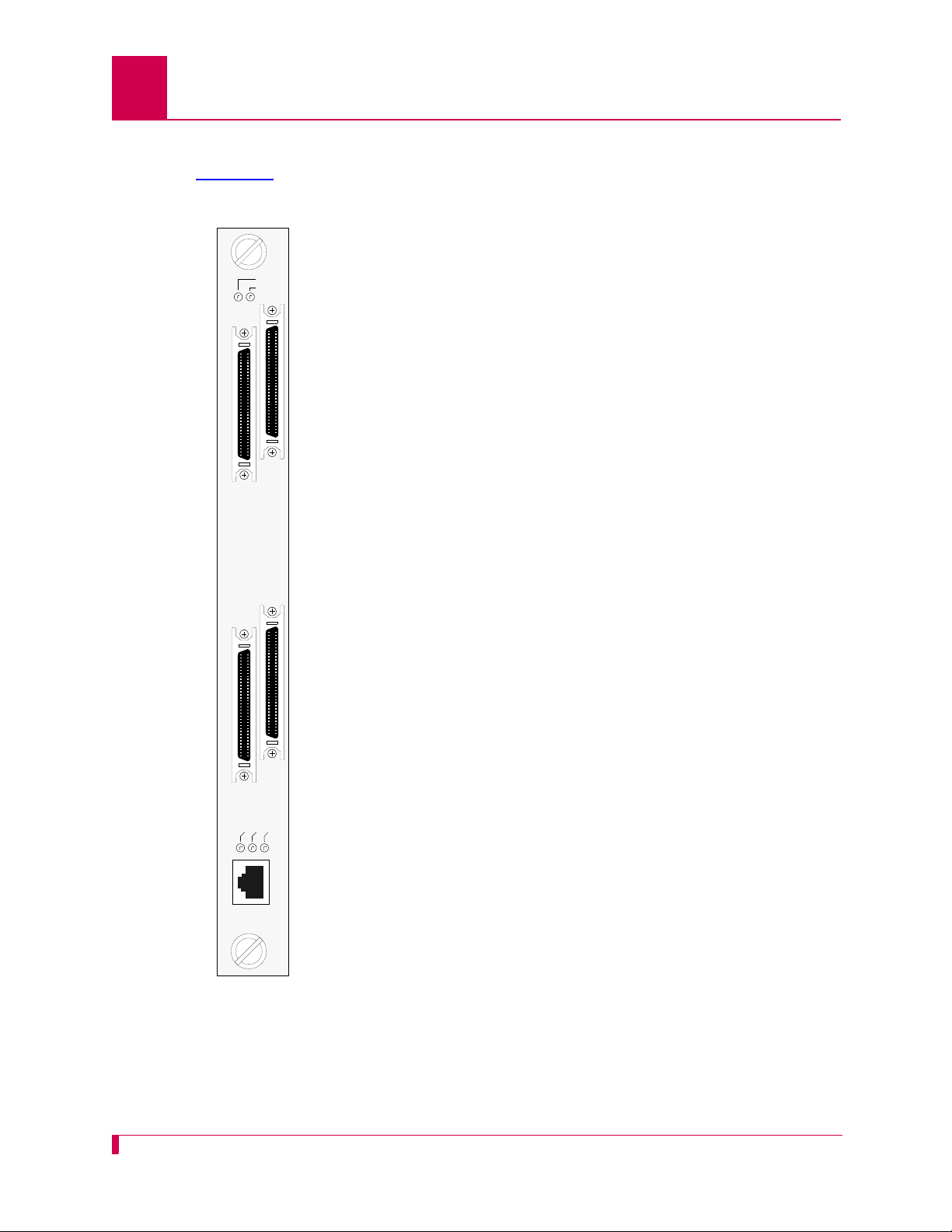
Front Panel Components
Figure 1-1 displays the AI296 front panel components.
DC OK LED Illuminates green when +5 Volts are
present.
FAULT LED Illuminates red if the card fails.
LINKS 5-8 Connector Provides four asynchronous, HDLC-
Bridge, PPP or X.25 ports.
LINKS 13-16 Connector Provides four asynchronous, HDLC-
Bridge, PPP or X.25 ports.
LINKS 1-4 Connector Provides four asynchronous, HDLC-
Bridge, PPP or X.25 ports.
LINKS 9-12 Connector Provides four asynchronous, HDLC-
Bridge, PPP or X.25 ports.
ACT LED Illuminates green when the card is
transmitting or receiving packets.
LINK LED Illuminates green when valid link integrity
pulses are being received.
COL LED Illuminates red when collisions are
detected.
10BASET
Connector Specifies the external 10BaseT port
connector.
Figure 1-1
1-6
AI296

Technical Specifications
Table 1-1 lists the AI296 technical specifications.
Table 1-1 Technical Specifications
Component Description
I/O Ports 16 asynchronous, HDLC-Bridge, PPP or X.25 (selectable
per port during configuration)
Note: Individual ports are derived by using a CAB257 cable
Port Speed 300 bps to 128 Kbps or exte rnal clocking (selectable per port
during configuration)
Electrical Interfaces RS-232, RS-530, and V.35 (selectable per port during
configuration)
AI296 Version 9.8x User’s Guide
Product Description: Technical Specifications
assembly for each connector or by using the Model
DP196 distribution panel.
Installation Requires one slot in an AI chassis (can be hot swapped)
Current Draw 4.2 A at +5 VDC, maximum
Compliance For use with AI UL Listed AIswitch Series Chassis.
1-7
AI296 Version 9.8x User’s Guide
LINK 1 LINK 5
LINK 2 LINK 6
LINK 3 LINK 7
LINK 4 LINK 8
LINK 1 LINK 5
LINK 2 LINK 6
LINK 3 LINK 7
LINK 4 LINK 8
Product Description: Individual Port Access
Individual Port Access
Individual ports are accessed by using a cable assembly or a distribution panel. AI2 96
uses the following components to derive ports:
z CAB257 Cable
z DP196 Distribution Panel
CAB257 Cable
The CAB257 cable has a multi-connector end that provides four DB-25 connectors.
Four CAB257 cables are needed to derive all 16 ports.
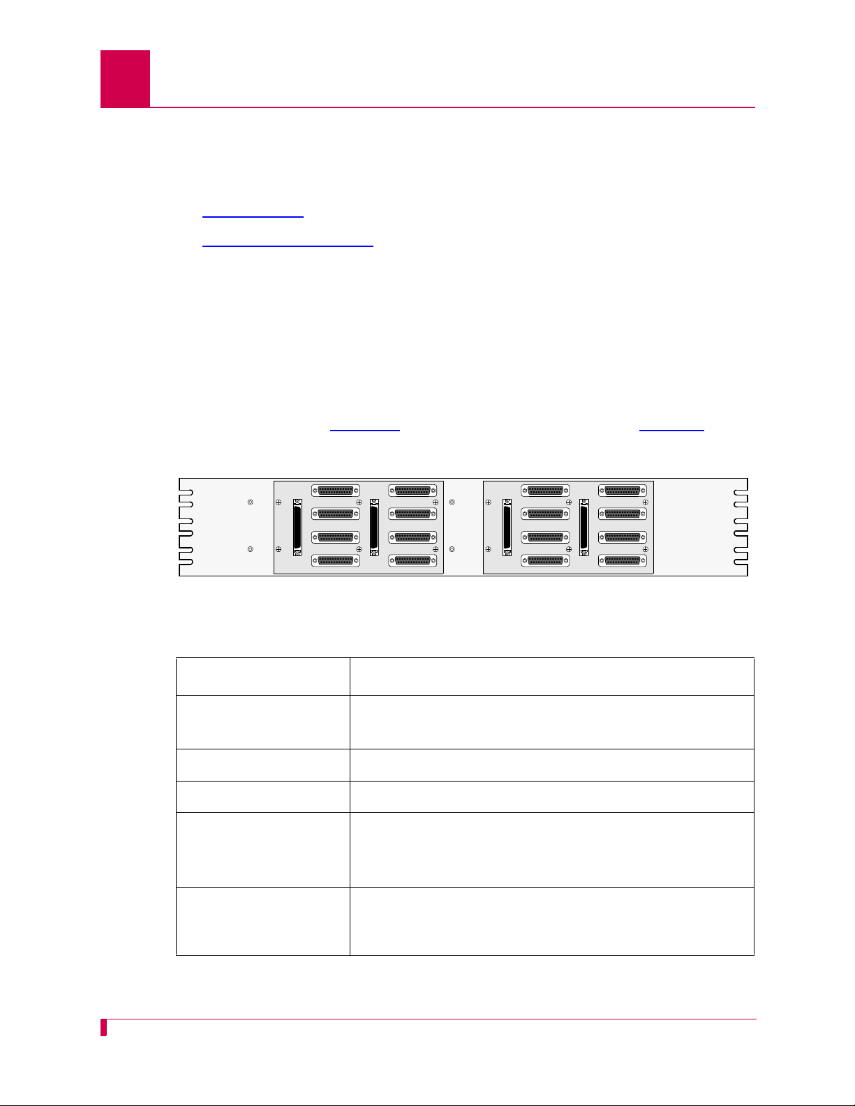
DP196 Distribution Panel
The DP196 distribution panel provides the physical interface for AI296 with sixteen
DB-25 connectors. The distribution panel is available in two sizes for 19-inch or 23inch rack installations. Figure 1-2
the specifications.
displays the distribution panel and Table 1-2 lists
Figure 1-2 DP196-19/23 Distribution Panel
Table 1-2 DP196-19/23 Specifications
Description Specification
Mounting DP196-19—Mounts to a 19-inch rack
DP196-23—Mounts to a 23-inch rack
I/O Ports Sixteen DB-25 connectors
Weight (approximately) 2.5 lb. (1.12 kg)
Size Height: 4 in. (10.16 cm)
Width: 19 in.(48.26cm)/23in. (58.42 cm)
Depth: 1.12 in. (2.84 cm)
Cable CAB162—Connects one connector (4 ports) on AI296 to
the distribution panel. Each distribution panel requires
four cables.
1-8
AI296 Version 9.8x User’s Guide
Pin 25
Pin 1
Pin 14
Pin 13
Product Description: Individual Port Access
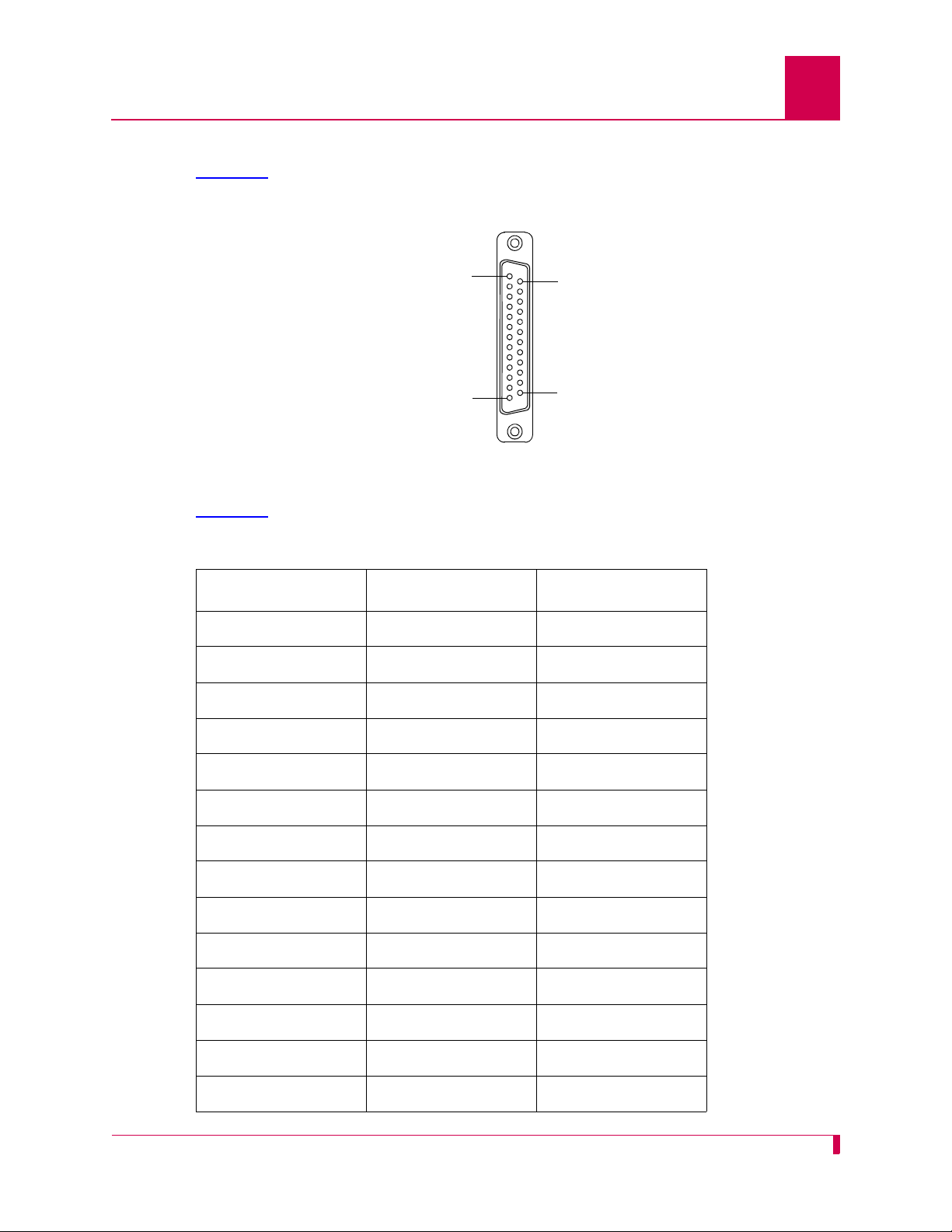
DB-25 Connectors
Table 1-3 displays pin assignments for the DB-25 connectors on the DP196-19/23
distribution panel.
Figure 1-3 DB-25 connector Pin Assignments
Table 1-3
displays the DP196-19/23 pin assignment specifications.
Table 1-3 DP196-19/23 Pin Assignment Specifications
Pin Signal Direction
2 TXD- Output
3 RXD- Input
4 RTS- Output
5 CTS- Input
7 Signal GND ---8 DCD- Input
9 RXC+ Input
10 DCD+ Input
12 TXC+ Either
13 CTS+ Input
14 TXD+ Output
15 TXC- Either
16 RXD+ Input
17 RXC- Input
1-9

AI296 Version 9.8x User’s Guide
Pin 1 Pin 8
Product Description: Individual Port Access
Table 1-3 DP196-19/23 Pin Assignment Specifications (Continued)
Pin Signal Direction
19 RTS+ Output
20 DTR- Output
23 DTR+ Output
The following characteristics apply to pin assignments:
z Any pin assignment not referenced on a connector is not connected.
z Signals with a (-) sign after them are used when RS-232 is selected.
z Signals with both (+) and (-) after them are used when RS-530, V.35, or V.11 are
selected.
z When RS-530 is selected, both the (+) and the (-) signals are used. The DSR is
only supported in RS-232 mode. There is no DSR+ signal.
Note: The pin assignments also apply to CAB257.
RJ45 10BaseT Connectors
Figure 1-4 displays the RJ45 10BaseT connector.
Figure 1-4 RJ45 10BaseT Connector on an AI296 Front Panel
Figure 1-4
Pin Signal Direction
1 TD+ Output
2 TD- Output
3 RD+ Input
lists the specifications for the RJ45 10BaseT connector.
Table 1-4 RJ45 10BaseT Connector Specifications
6 RD- Input
CAB182 cables connect network elements to the individual connectors on the
distribution panel (straight through applications).
1-10
Typical Applications
Asynchronous NE
Asynchronous NE
Asynchronous NE
Operating Support System
AI296
IP Network
AI296 is used primarily for X.25 trunking and connecting different types of network
elements. The following applications are discussed in this section:
z Asynchronous to TCP/IP Application
z IP Over X.25 Networks
z Mixed Asynchronous and X.25 Networks
z X.25 to TCP/IP Application
z X.25 Trunking
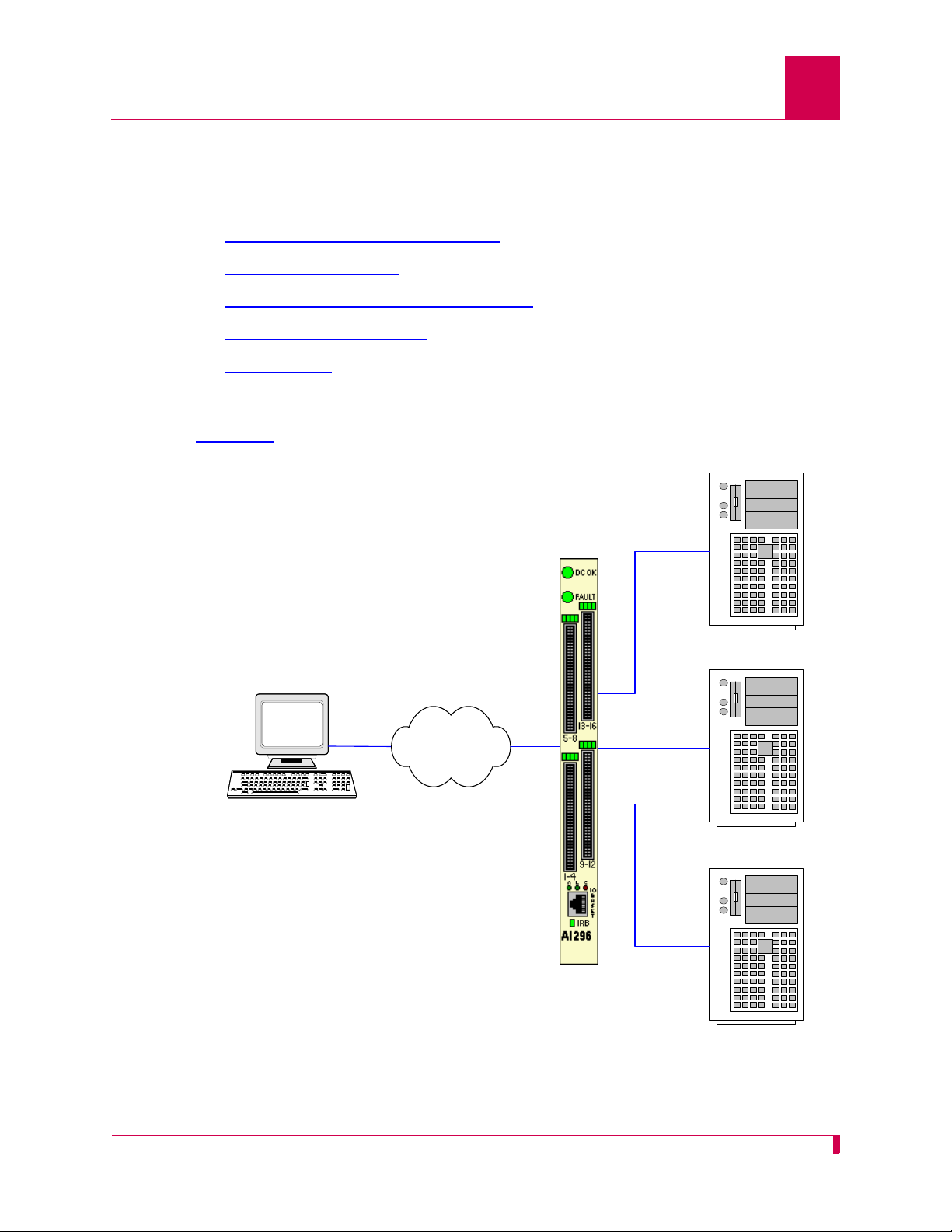
Asynchronous to TCP/IP Application
Figure 1-5 illustrates an asynchronous to TCP/IP application.
AI296 Version 9.8x User’s Guide
Product Description: Typical Applications
Figure 1-5 Asynchronous to TCP/IP Application
1-11
AI296 Version 9.8x User’s Guide
AI296 AI296
SNMP
Manager
SNMP
Manageable
Device
(example
AI198)
IP Over Ethernet
IP Over Ethernet
IP Network
IP Network
X.25 Packet
Network
Product Description: Typical Applications
The following events occur in Figure 1-5:
z The OSS sends TCP/IP calls to AI296.
z AI296 routes the TCP/IP calls to an asynchronous NE using an asynchronous
port.
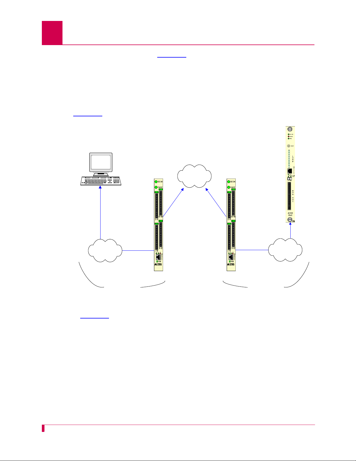
IP Over X.25 Networks
Figure 1-6 illustrates a common IP over X.25 application.
1-12
Figure 1-6 IP Over X.25 Network
In Figure 1-6
, AI296 is used to tunnel IP traffic through an X.25 network. AI296 can be
configured to encapsulate IP packets, making it possible to achieve IP connectivity
across a legacy X.25 network. The most common application for this functionality is to
transport SNMP management information across an X.25 network.
Important: IP/X.25 transport works only over SVCs.

AI296 Version 9.8x User’s Guide
Product Description: Typical Applications
Figure 1-6 on page 1-12 illustrates the following events:
z The SNMP Network Manager (for example, AppliedView) sends TCP/IP calls over
an IP/Ethernet network to AIswitch (AI296).
z AI296 encapsulates the TCP/IP calls within X.25 SVC calls and sends them
through the X.25 packet network.
z The X.25 packet network sends the X.25 calls to a remote AIswitch (AI296).
z The remote AI296 returns the X.25 calls to TCP/IP calls based on its static routing
tables.
z AI296 sends the TCP/IP calls over the IP/Ethernet network to the
SNMP-managed device (for example, AI198).
1-13
AI296 Version 9.8x User’s Guide
X.25 Packet
Network
DDM 2000
FLM 150
Titan DACS
DDM 2000
FLM 150
Titan DACS
AI296
AI296
Operating
Support System
Asynchronous NE
IRB
Product Description: Typical Applications
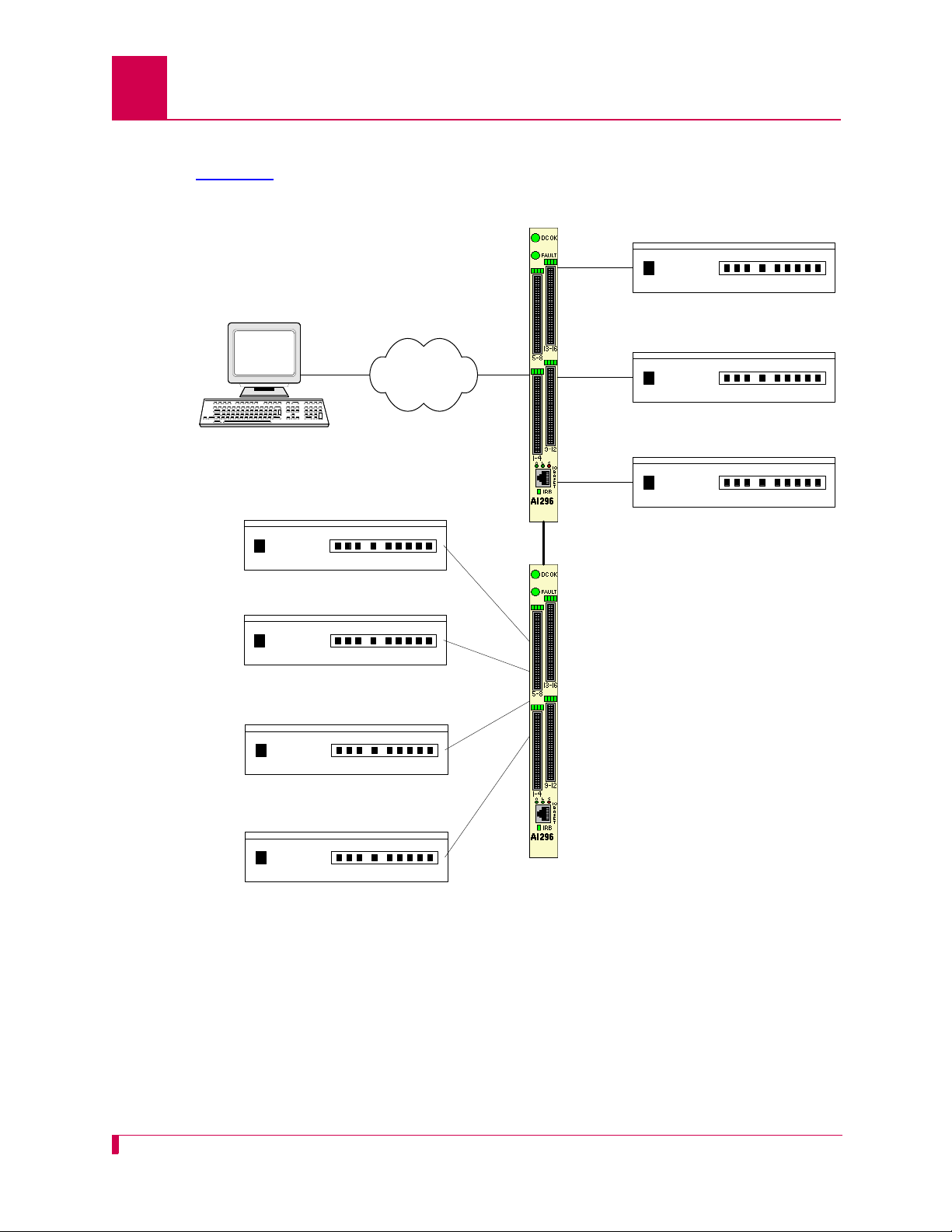
Mixed Asynchronous and X.25 Networks
Figure 1-7 illustrates both X.25 network elements and asynchronous network
elements connected to a remote OSS using a single X.25 trunk.
Figure 1-7 Mixed Asynchronous and X.25 Network
1-14

AI296 Version 9.8x Use r’s Guide
Product Description: Typical Applications
Figure 1-7 illustrates the following events:
z The OSS sends X.25 calls through an X.25 packet network to AI296.
z AI296 makes call routing decisions based on the AI198 routing alias.
z AI296 sends local X.25 calls directly to the attached NEs.
z The local AI296 converts local X.25 calls to TCP/IP calls and routes them over the
IRB to a remote AI296. Routing is based on the routing aliases configured in
AI198.
z The remote AI296 sends asynchronous calls to the attached asynchronous NEs.
1-15

AI296 Version 9.8x User’s Guide
AIswitch
Operating
Support System
X.25 NE
X.25 NE
X.25 NE
IRB
AIfocus AI296
AIswitch
TCP/IP Network
X.25
TCP/IP
X.25
Product Description: Typical Applications
X.25 to TCP/IP Application
Figure 1-8 illustrates a common X.25 to TCP/IP application. X.25 network elements
are connected to a router network using a TCP/IP LAN.
Figure 1-8 X.25 to TCP/IP Application
Figure 1-8
z The OSS sends X.25 calls to AIswitch.
z AIswitch converts X.25 calls to TCP/IP calls and sends them over the router
illustrates the following events:
network.
z The router network carries the TCP/IP calls to AIfocus
z AIfocus sends the TCP/IP calls over the IRB to AI296.
z Based on the AI198 routing alias, AI296 converts the TCP/IP calls to X.25 calls.
z AI296 sends X.25 calls to the attached X.25 NEs.
TM
.
Like other AIswitch line cards, AI296 terminates X.25 connections and extracts the
data from them. Unlike other line cards, AI296 can convert the X.25 connections to
TCP/IP connections across the IRB. The ultimate destination for these TCP/IP
connections may be one of the following:
z An IRB-connected line card in the same chassis, such as another AI296 or an
AI193-TX
z A locally connected TCP/IP host
TM
1-16
z A remote TCP/IP host, indirectly connected to AIswitch using a router network.
When AI296 establishes a TCP/IP connection to an external device, the IP packets
are exported from AIswitch by AIfocus or by an AI router.

X.25 Trunking
X.25 Packet
Network
X.25 NE
X.25 NE
X.25 NE
X.25 NE
X.25 NE
X.25 NE
AI296
AI296
Operating
Support System
Figure 1-9 illustrates a common X.25 trunking application.
AI296 Version 9.8x Use r’s Guide
Product Description: Typical Applications
Figure 1-9 X.25 Trunking
1-17

AI296 Version 9.8x User’s Guide
Product Description: Typical Applications
Figure 1-9 illustrates the following events:
z The OSS sends X.25 calls through an X.25 packet network (over an X.25 trunk) to
AI296.
z AI296 makes call routing decisions based on the AI198 routing alias.
z AI296 sends local X.25 calls directly to its attached NEs. X.25 NEs are connecte d
to the OSS with a single X.25 trunk.
z AI296 converts local X.25 calls to TCP/IP calls and sends them over the IRB to a
remote AI296.
z The remote AI296 sends remote X.25 calls directly to its attached network
elements.
1-18

2
Using the AI198
This chapter provides information on starting, ending, and navigating through an AI198 menu
system session.
Guide to this Chapter
Accessing the Menu System
Navigating the Menu System
Exiting the Menu System
TM
Menu System
2-1

AI296 Version 9.8x User’s Guide
Using the AI198TM Menu System: Accessing the Menu System
Accessing the Menu System
To access the AI198 menu system:
1. Log into AI198.
2. At the prompt, enter
>menu
Main Menu
01+Configure options affecting the system as a whole
02+Create, delete, or modify a destination name
03+Display all destination names
04+Configure cards
05+Set or remove connection restrictions based on port numbers
06+Display all connection restrictions
07+Configure slot density
08+Configure the alias translation table
09+Display the list of alias translation entries
10+Configure the BOOTP table
21 Exit the configuration menu system
Enter item number and optional ",value" then push <CR> key
>
menu. The Main Menu appears.
2-2

Using the AI198TM Menu System: Navigating the Menu System
Navigating the Menu System
Menu Numbering Structure
All menus accessed from the Main Menu are identified with a numerical reference at
the top right corner of the menu screen. This numerical reference specifies the
location within the menu system. Each digit in the menu number represents a menu
item that was previously selected. For example, Menu 4.2 indicates that menu item
2 were selected.
and
>2
Menu 4.2
01 Configure as Empty Slot
02+Configure as AI183/AI185 standard 4/16 port card
03+Configure as AI193/194 Ethernet card with slot expansion of----04+Configure as AI192/196 X.25 network card with slot expansion of-------05+Configure as ASP or Advanced Smart Line Card with slot expansion of-------06 Configure as AI196-I network card with LocalView
07 Configure as AI2524 Router card
08 Configure as AI294 Ethernet Switch card
09+Configure as AI196-I network interface card with menu support
10 Configure as Independent Smart Line Card
11+Configure as AI296 network interface card
12+Configure as AI192/196 with full menu support and slot expansion of-------13+Configure as AI285 network interface card
14+Configure as AI232 network interface card
15 Configure as AI Modem
16 Configure as AIFlex Fiber LAN Extender Card
17 Configure as AI120 Card
18 Configure as AIE1 Card
19 Configure as AITC Card
20 Next Page
21 Exit this menu with no changes
Enter item number and optional ",value" then push <CR> key
>
AI296 Version 9.8x Use r’s Guide
4
Types of Menu Items
The following four types of menu items are available:
z Submenus
z Toggles
z Data
z Functions
2-3

AI296 Version 9.8x User’s Guide
Using the AI198TM Menu System: Navigating the Menu System
Submenus
Submenus go to deeper levels in the menu hierarchy. They provide additional
configuration menus. Menu items that contain submenus have a plus sign (
their menu item number. In this example, menu item
02+Configure as AI232 network interface card
02 will display a submenu.
+) next to
Some submenus require a selection from a list and then re-display the previous menu
showing the selection. Other submenus have their own submenus that request
additional information. After saving the entries, the top-level menu re-appears.
Toggles
Toggles display two or more values that can be selected for a parameter. Toggles
have an asterisk (
toggles to the next selection.
*) next to their menu item number. Entering the menu item number
In this example, menu items
06*TCP Default Window Size (200, 512, 1024, 2048)-------------------------- 200
07*TCP Send Ahead-----------------------------------------------------------OFF
06*TCP Default Window Size, the user can toggle between values 200, 512, 1024, and
For
2048. For 07*TCP Send Ahead, the user can toggle between ON and OFF.
06 and 07 are toggles.
Data
Data menu items request text entries (such as destination names and card
descriptions) or numeric values (such as port numbers and IP addresses). To enter
information in a data menu item, enter the menu item number followed by a comma
(or a space) and the configuration information.
In this example, the menu item requires an IP address entry.
01 IP Address (0.0.0.0 - 255.255.255.254)------- ----------------000.000.000.000
To enter an IP address of 172.016.002.043, enter the following:
1,172.016.002.043
The menu re-appears with the entered IP address.
2-4
01 IP Address (0.0.0.0 - 255.255.255.254)------- ----------------172.016.002.043
To change configuration data that has been entered for a menu item, enter the menu
item number followed by a comma and the new data.

AI296 Version 9.8x Use r’s Guide
Using the AI198TM Menu System: Navigating the Menu System
Tip: To change a typed entry, use BACKSPACE to back up to the desired position in
the text and retype the changes. However, once the user presses ENTER,
changes can be made only by selecting that menu item and re-entering the
data.
Functions
Menu item functions appear at the bottom of each menu. This example displays menu
items that can appear and Table 2-1
17 Display first page
18 Next page
19 Delete entry
20 Save the changes made
21 Exit this menu with no changes
Enter item number and optional ",value" then push <CR> key
>
describes them.
Table 2-1 Menu Item Descriptions
Menu Item Description
17 Displays the first page of a menu.
18 Displays additional pages of a menu.
19 Deletes information for a specified entry.
20 Saves the entered information and re-displays the previous related
menu.
Important: Configuration entries take effect only after every screen
has been saved going back to the main menu.
21 Exits a menu without saving changes. All items on the menu return to
the previously configured values.
2-5

AI296 Version 9.8x User’s Guide
Using the AI198TM Menu System: Exiting the Menu System
Exiting the Menu System
To exit the menu system:
1. Access the Main Menu.
2. Enter
21. The command prompt appears.
2-6

3
AI296 Local Menu System
This chapter provides information on the configuration and navigation of the AI296 menu system.
This system offers on-board configuration capabilities similar to those available in the AI198
menu system. The AI296 menu system is available when the card is operating in both switch
mode and standalone mode.
Guide to this Chapter
Identifying AI296 Menu System Security Options
Logging Into AI296
Accessing the Local Menu System
Navigating the Local Menu System
Accessing the Help Menu
Exiting the Local Menu System
3-1

AI296 Version 9.8x User’s Guide
AI296 Local Menu System: Identifying AI296 Menu System Security Options
Identifying AI296 Menu System Security Options
AI296 has a variety of security options, including:
z Multilevel User Name and Password Security
z RADIUS Authentication
z TACACS+ Authentication
z PPP Authentication Protocols (PAP and CHAP)
Multilevel User Name and Password Security
Up to 10 configurable user account profiles can be assigned to an AI296 user. Five
system profiles are available for providing various levels of user access. For more
information about user profiles, refer to command profile on page 1-103.
RADIUS Authentication
RADIUS authentication verifies user login information against valid user information in
a database on a centralized RADIUS authentication server. A primary and secondary
RADIUS server are configurable to provide secure access for an entire AI296
network. AI296 RADIUS authentication is available for Telnet, asynchronous, and
synchronous ports. For more information on RADIUS authentication, refer to section
RADIUS Configuration on page 1-19.
TACACS+ Authentication
T ACACS+ authentication verifies user login information against the user’s permission
level on a TACACS+ server. Up to 9 TACACS+ servers are configurable to provide
secure access for an entire AI296 network. AI296 TACACS+ authentication is
available for Telnet, asynchronous, and FTP connections. For more information on
TACACS+ authentication and server configuration, refer to the following commands:
z aaa
z tacacs
z tacacs server
PPP Authentication Protocols (PAP and CHAP)
All asynchronous and synchronous PPP links are configurable to use either PAP or
CHAP PPP authentication protocols. PAP establishes peer identity using a 2-way
handshake that is done only upon initial link establishment. CHAP performs a 3-way
handshake upon initial link establishment, then proceeds to verify the link with 3-way
handshakes at random intervals. CHAP also encrypts the user’s password over the
PPP link to provide added security.
3-2

Logging Into AI296
Log into AI296 with a Telnet connection or with any of AI296’s asynchronous ports
that are configured as Login ports.
Note: ai is the default user ID and password. AI296 prompts you to create a new
user ID and password after the fifth login with the default values. Refer to
command useradd on page 9-118
Using a Telnet Connection for Login
Logging in using a Telnet connection requires that AI296 has a configured IP address.
If an IP address has not been configured, refer to Chapter 4: System Configuration
assign an IP address.
To log into AI296 using a Telnet connection:
1. Power on AI296.
2. Connect the Ethernet network connection to the 10BaseT port on the front panel
of AI296.
AI296 Version 9.8x Use r’s Guide
AI296 Local Menu System: Logging Into AI296
to create a new user ID and password.
to
3. Telnet to AI296. The login prompt appears.
Note: ai is the default user ID and password. There are five grace period logins.
If after the fifth login a new ID and password have not been created, AI296
prompts you to create a user ID and password. Use the useradd
command described in Chapter 9: AI296 Commands
and password.
4. Enter your user ID. The password prompt appears.
5. Enter your password. The destination menu appears. You are now logged into
AI296.
The following message appears when AI296 is configured to contact a TACACS+
server during authentication:
login: test
Password:
Contacting TACACS+ server. Please wait.
to create a user ID
3-3

AI296 Version 9.8x User’s Guide
AI296 Local Menu System: Logging Into AI296
The following message appears when AI296 is configured to contact a TACACS+
server during authentication, but the contact attempt fails:
login: test
Password:
Contacting TACACS+ server. Please wait.
TACACS+ server(s) not responding.
Note: Five consecutive failed login attempts generate an SNMP trap and a log
message saying that the login failed. Also, an entry appears in th e log file with
text stating
Warning:
x
consecutive failed login attempts where x is the number
of consecutive failed login attempts.
Using an Asynchronous Port for Login
Two tools are required for logging into AI296 using an asynchronous port:
z A PC with terminal emulation software such as HyperTerminal (included with
Windows 95/98/2000/XP) or ProComm.
z Terminal cable with these specifications: null (RS232) cable with DB25 male
connector for AI296 distribution panel connection and appropriate connector for
your PC.
To log into AI296 using an asynchronous port:
1. Set the terminal emulation software to the following settings:
z 9600 baud
z No parity
z Eight data bits
z One stop bit
2. Power on AI296.
3. Connect a PC to port 1 on the DP232 distribution panel.
Note: Link 1 on AI296 is enabled and configured for login by default, which
allows access through the link. AI296 may also be accessed through any
asynchronous link that is enabled and configured for login.
4. Press ENTER. The login prompt appears.
5. Enter your user ID. The password prompt appears.
6. Enter your password. The destination menu appears. You are now logged into
AI296.
3-4

AI296 Version 9.8x Use r’s Guide
AI296 Local Menu System: Logging Into AI296
The following message appears when AI296 is configured to contact a TACACS+
server during authentication:
login: test
Password:
Contacting TACACS+ server. Please wait.
The following message appears when AI296 is configured to contact a TACACS+
server during authentication, but the contact attempt fails:
login: test
Password:
Contacting TACACS+ server. Please wait.
TACACS+ server(s) not responding.
Note: Five consecutive failed login attempts generate an SNMP trap and a log
message saying that login failed. Also, a new entry will appear in the log
file with text stating
Warning:
x
consecutive failed login attempts where
the number of consecutive failed login attempts.
x
is
3-5

AI296 Version 9.8x User’s Guide
AI296 Local Menu System: Accessing the Local Menu System
Accessing the Local Menu System
To access the AI296 menu session:
1. Log into AI296. Refer to section Logging Into AI296 on page 3-3
information.
2. At the destination menu, enter
3. Enter
menu. The AI296 Main Menu appears.
+ Link Menu
+ Alias Menu
+ System Menu
+ Static Route Menu
....................................................................
: :
: Select the desired menu option using the UP or DOWN arrow key. :
: Then press ENTER or RETURN to continue. :
:..................................................................:
ai. The AI296 shell prompt appears.
AI296 Main Menu
for more
3-6
<F1> Help <F4> Close
Note: The Alias Menu is only available when you log into AI296 in standalone mode.

AI296 Version 9.8x Use r’s Guide
AI296 Local Menu System: Navigating the Local Menu System
Navigating the Local Menu System
Arrow keys and keyboard short cuts can be used to navigate through the local menu
system. Refer to Table 3-1
Note: To use the arrow keys in the menu system, make sure the VT100 arrow keys
are enabled in either your Telnet settings or your terminal emulation program.
Direction Keys
Up Use the up arrow key or Press <Ctrl-p>
Down Use the down arrow key or Press <Ctrl-n>
Right Use the right arrow key or Press <Ctrl-f>
Left Use the left arrow key or Press <Ctrl-b>
for a list of arrow key movements and keyboard shortcuts.
Table 3-1 Direction Keys
Identifying Types of Menu Items
The AI296 local menu system contains data items that let you input information or
toggle between available selections.
Data Entry Items
The following screen shot displays an example of a data entry menu item:
Link to configure . . . . . . . . . . . . . . . . . . . . . . . . . . . . 1
To enter information for a data entry menu item:
1. Move the cursor to the menu item.
Note: If the selected menu item has a range of valid values, that range will
appear in the bottom right of the screen.
2. Enter your data.
To erase existing data for a data entry menu item:
1. Move the cursor to the menu item.
2. Delete the data using BACKSPACE or DELETE and press ENTER.
OR
Enter new data.
3-7

AI296 Version 9.8x User’s Guide
AI296 Local Menu System: Navigating the Local Menu System
To save your changes:
z Press F2 (or use the up and down arrow keys to highlight [Send]) and ENTER.
z Enter y to save. If an error message appears, check your work and make change s
as necessary.
z Press CTRL-E to save data entries immediately without being queried to save. If
an error message appears, check your work and make changes as necessary.
Togg le Items
The following screen shot displays an example of a toggle menu item. The selected
option has brackets around it.
Link state . . . . . . . . . . . . . . . . . . . . . . . . . . [Up] Down
To select a value for a toggle menu item:
1. Move the cursor to the menu item.
2. Highlight the option you want to select and press ENTER. The brackets move to
that option.
To save your changes:
z Press F2 (or use the up and down arrow keys to highlight [Send]) and ENTER.
z Enter y to save. If an error message appears, check your work and make change s
as necessary.
z Press CTRL-E to save data entries immediately without being queried to save. If
an error message appears, check your work and make changes as necessary.
3-8

Accessing the Help Menu
The AI296 help menu lists all available keyboard codes and function keys with their
associated purposes. The help menu can be accessed by doing one of the following
things:
z Pressing F1 and ENTER
z Selecting Help on the menu and ENTER
z Pressing ESC-1 and ENTER.
The following example displays the first page of the local menu system help screen:
Navigation Help Page 1 of 4
This screen displays when you press the <F1> key or if you enter an invalid keystroke from the Main Menu. The following keyboard function keys are programmed
to allow you to enter or change data in menus:
AI296 Version 9.8x Use r’s Guide
AI296 Local Menu System: Accessing the Help Menu
<F1>; <F2>; <F4>; UP Arrow; DOWN Arrow; LEFT Arrow; RIGHT Arrow
If you can not locate these keys on your keyboard, use the following keyboard
equivalent codes to provide the same functionality:
Keyboard Code Function Key Purpose
Esc 1 <F1> HELP - displays this help screen from any menu.
Esc 2 <F2> SEND - transmits the currently displayed data. You
are given a confirmation prompt before the actual
transmittal of data occurs. When you press the <F2>
key, the RIGHT and LEFT arrow keys can then be used
to access the other commands.
Press SPACE BAR to continue, or 'q' to quit
3-9

AI296 Version 9.8x User’s Guide
AI296 Local Menu System: Exiting the Local Menu System
Exiting the Local Menu System
To exit the local menu system and save all changes:
1. Select
<F2> Send and press ENTER.
The following prompt appears:
Save changes? (y/n)
2. Save the changes:
y
3. Select <F4> Close and press ENTER until you are out of the menu system.
To exit the local menu system without saving changes, execute step 3
.
Note: Entering <CTRL> + R takes you directly to the main menu.
3-10

4
System Configuration
This chapter provides information on configuring AI296 system settings with the AI198 menu
system and the AI296 local menu system. To configure AI296 with the AI198 menu system, the
AI198 software must be at version 1.90 or later . The AI198 menu syste m settings take ef fect only
when AI296 is operating in switch mode (non-standalone mode).
Guide to this Chapter
General System Properties Configuration
RADIUS Configuration
TACACS+ Configuration
SNMP Configuration
Static Route Configuration
TID to Modem Mux Configuration
Time Configuration
4-1

AI296 Version 9.8x User’s Guide
System Configuration: General System Properties Configuration
General System Properties Configuration
General system properties are configurable at the first level of the AI198 and AI296
System menu. The following menu items can be configured:
z Destination Menu Break Sequence
z Ethernet Port Settings
z FTP Port
z IP Settings
z Passive Link Settings
z System Prompt
z TCP Settings
z Telnet Port
Destination Menu Break Sequence
Description
This menu item sets the character sequence that lets the user exit a connection from
the destination menu.
Format
Destination menu break sequences take the following format:
attention_keystroke
attention_keystroke
[
delay_start, delay_end
]
next_character
Defines the keystroke that indicates that a break
sequence is coming. Valid values are:
z <
x
> where
x
represents the decimal ASCII value
of the keystroke. For example, enter
represent the TAB key.
z <c>
x
where <c> represents the CTRL key and
represents the actual key name. For example,
enter
<c>^ to represent CTRL+SHIFT+6.
z <c><
x
> where <c> represents the CTRL key and
represents the decimal ASCII value of the actual
key name. For example, enter
<c><9> to represent
CTRL+TAB.
<9> to
x
x
4-2
delay_start
Defines the amount of time (in seconds) you must wait
before entering the next character. Valid values are
integers from 0 to 8.

AI296 Version 9.8x Use r’s Guide
System Configuration: General System Properties Configuration
delay_end
next_character
Defines the amount of time (in seconds) before which
you must enter the next character. Valid values are
integers from 1 to 9.
Note: If you do not enter the next character within the
configured time frame, then both the
attention_keystroke
and
next_character
values are treated as data and forwarded.
Defines the next character in the sequence. Valid
values are:
z <
x
> where
of the keystroke. For example, enter
x
represents the decimal ASCII value
<9> to
represent the TAB key.
z <c>
x
where <c> represents the CTRL key and
x
represents the actual key name. For example,
<c>^ to represent CTRL+SHIFT+6.
enter
z <c><
x
> where <c> represents the CTRL key and
x
represents the decimal ASCII value of the actual
key name. For example, enter
<c><9> to represent
CTRL+TAB.
Note: You can include multiple characters with delays between each in the break
sequence. For example,
<c>^[1,5]x[0,9]k is a valid entry.
Menu Item Type
Data
Configuration in the AI198 Menu System
1. Access Menu 4.2.11 pg 2.
2. From Menu 4.2.11 pg 2, enter
sequence. The maximum length is 44 characters. The default is
This example displays item
<c>^[2,6]x.
>3,<c>^[2,6]x
Menu 4.2.11 pg 2
01*10 Base T Ethernet-------------------------------------------------------OFF
02+Radius Configuration Menu
03 Destination Menu Break Sequence-----------------------------------<c>^[2,6]x
03 Destination Menu Break Sequence configured as
3, and the desired destination menu break
<c>^[1,5]x.
4-3

AI296 Version 9.8x User’s Guide
System Configuration: General System Properties Configuration
Configuration in the AI296 Local Menu System
1. Access the System Menu.
2. Enter a character sequence for
is 44 characters. The default is
The following example displays item
System Prompt . . . ................................................. [232]
Destination Menu Break Sequence . . . . . . . ..................... <c><33>
Ethernet Port Settings
Description
The Ethernet port settings are configured using two menu items:
z 10BaseT Ethernet—Enables or disables the 10BaseT Ethernet port on the front
panel of AI296.
z Dual Ethernet—Enables or disables simultaneous operation of the faceplate
mounted 10BaseT Ethernet port and the IRB.
Destination Menu Break Sequence. Maximum length
<c>^[1,5]x.
Destination Menu Break Sequence set to <c><33>.
System Menu
Note: When the dual Ethernet setting is enabled, the 10BaseT Ethernet setting
has no effect on AI296 operation.
Menu Item Type
Toggle for both menu items
Configuration in the AI198 Menu System
1. Access Menu 4.2.11 pg 2.
2. For
3. For
This example displays
01*10 Base T Ethernet, enter 1 to select OFF or ON. The default is OFF.
07*Dual Ethernet, enter 7 to select OFF or ON. The default is OFF.
01*10 Base T Ethernet set to ON and 07*Dual Ethernet set to OFF.
>7
Menu 4.2.11 pg 2
01*10 Base T Ethernet---------- ------------------------------------------- -- ON
02+Radius Configuration Menu
03 Destination Menu Break Sequence----------- ------------------------<c>^[1,5]x
04+TACACS Configuration Menu
05 TCP Outgoing Connection Timer (2-360s)-----------------------------------075
07*Dual Ethernet (On, Off)--------------------------------------------------OFF
4-4

AI296 Version 9.8x Use r’s Guide
System Configuration: General System Properties Configuration
Configuration in the AI296 Local Menu System
1. Access the System Menu.
2. For
3. For
This example displays
FTP Port
Description
This menu item sets the FTP server port number.
10 Base T Ethernet, select Off or On. The default is off when running in switch
mode. The default is
Dual Ethernet, select Off or On. The default is Off.
System Prompt . . . ................................................. [232]
Destination Menu Break Sequence . . . . . . . ..................... <c><33>
TCP Default Window Size . . . . . . . . . . [200] 512 1024 2048
TCP Send Ahead . . . . . . . . . . . . . . . . . . . . . . . On [Off]
Telnet Port . . . . . . . . . . . . . . . . . . . . . . . . . . . . ... 23
FTP Port . . . . . . . . . . . . . . . . . . . . . . . . . . . . . . ... 21
10 Base T Ethernet . . . . . . . . . . . . . . . . . . . . . Off [On]
Dual Ethernet . . . . . . . . . . . . . . . . . . . . . . . [Off] On
on when running in standalone mode.
10 Base T Ethernet set to ON and Dual Ethernet set to OFF.
System Menu
Menu Item Type
Data
Configuration in the AI198 Menu System
1. Access Menu 4.2.11.
2. For
16 FTP port number, enter 16, and the FTP server port number. Valid values are
1 to 65534. The default is 21.
4-5

AI296 Version 9.8x User’s Guide
System Configuration: General System Properties Configuration
This example displays 16 FTP port number set to 220.
>16,220
Menu 4.2.11 pg 1
01 IP Address (0.0.0.0 - 255.255.255.254)------- ----------------010.040.057.015
02 IP Address Range (1 - 255)---------------------- -------------------------001
03 IP Subnet Mask (0.0.0.1 - 255.255.255.254) ------------------255.255.000.000
04 Primary IP Router Address (0.0.0.0 - 255.255.255.254) -------010.040.000.001
05 Secondary IP Router Address (0.0.0.0 - 255.255.255 .254) -----000.000.000.000
06*TCP Default Window Size (200, 512, 1024, 2048)-------------------------- 200
07*TCP Send Ahead-----------------------------------------------------------OFF
08+SNMP System Parameters
09*Bring passive link down when all calls have cleared----------------------OFF
10 Passive link Stay Inactive timer--------------------------------------000060
11 Passive link Standby Mode timer---------------------------------------000025
12+Link Setup
13+IP Over X.25 Subnets
14+IP Static Routes
15 Telnet port number (1..65534)------------------------------------------00023
16 FTP port number (1..65534)---------------------------------------------00220
Configuration in the AI296 Local Menu System
1. Access the System Menu.
2. For
This example displays
IP Settings
Description
The IP settings are configurable using five menu items in the CLC menu or via a shell
command on AI296. The configurable values are:
z IP address
z IP address range
z IP subnet mask
FTP Port, enter the desired FTP port value. Valid values are from 0 to 65534.
FTP Port set to 1752.
System Menu
System Prompt . . . ................................................. [232]
Destination Menu Break Sequence . . . . . . . ..................... <c><33>
TCP Default Window Size . . . . . . . . . . [200] 512 1024 2048
TCP Send Ahead . . . . . . . . . . . . . . . . . . . . . . . On [Off]
Telnet Port . . . . . . . . . . . . . . . . . . . . . . . . . . . . ... 23
FTP Port . . . . . . . . . . . . . . . . . . . . . . . . . . . . . . . 1752
4-6
z Primary IP router address
z Secondary IP router address.

AI296 Version 9.8x Use r’s Guide
System Configuration: General System Properties Configuration
Menu Item Types
Data
Configuration in the AI198 Menu System
1. Access Menu 4.2.11.
2. For
3. For
4. For
5. For
6. For
01 IP Address, enter 1, and the IP address for AI296. The default is
000.000.000.000.
02 IP Address Range, enter 2, and the number of the IP addresses to be
assigned to AI296. The valid range is
03 IP Subnet Mask, enter 3, and the IP subnet mask for AI296. The default is
255.255.255.254.
04 Primary IP Router Address, enter 4, and the IP address of the primary router
for AI296. The default is
05 Secondary IP Router Address, enter 5, and the IP address of the secondary
router for AI296. The default is
000.000.000.000.
000.000.000.000.
1 to 255.
This example displays:
z 01 IP Address set to 10.38.49.12
z 02 IP Address Range set to 3
z 03 IP Subnet Mask set to 255.255.000.000
z 04 Primary IP Router Address set to 010.038.000.001
z 05 IP Router Address set to 010.038.000.002
>5,10.38.0.2
Menu 4.2.11 pg 1
01 IP Address (0.0.0.0 - 255.255.255.254)------- ----------------010.038.049.012
02 IP Address Range (1 - 255)---------------------- -------------------------003
03 IP Subnet Mask (0.0.0.1 - 255.255.255.254) ------------------255.255.000.000
04 Primary IP Router Address (0.0.0.0 - 255.255.255.254) -------010.038.000.001
05 Secondary IP Router Address (0.0.0.0 - 255.255.255 .254) -----010.038.000.002
Note: For information about configuring IP setting with shell commands, refer to
commands ip on page 9-56
and ip init on page 9-57.
4-7

AI296 Version 9.8x User’s Guide
System Configuration: General System Properties Configuration
Passive Link Settings
Description
The passive link settings are configured using three menu items. The configurable
values are:
z Passive link down state—Configures standby (DMlock) mode for a passive link.
When this feature is turned on, a passive link will go into DMlock mode after all
calls have cleared. When turned off, a pass ive link will sta y up when all calls have
cleared.
z Passive link stay inactive timer—Sets the number of seconds a passive link waits
for a connection to come up before failing.
z Passive link standby mode timer—Configures the amount of time a link remains in
standby mode before it becomes idle. Immediately after a passive link becomes
inactive, it goes into the standby (DMlock) mode.
Menu Item Types
Toggle for the passive link down state
Data for the passive link stay inactive timer and the passive link standby mode timer
Configuration in the AI198 Menu System
1. Access Menu 4.2.11.
2. For
3. For
4. For
09*Bring passive link down when all calls have cleared, enter 9 to select ON or
OFF. The default is OFF.
10 Passive link Stay Inactive timer, enter 10, and a value in seconds for the
passive link stay inactive timer. The minimum value is
60 seconds.
is
11 Passive link Standby Mode timer, enter 11, and a value in seconds for the
passive link standby mode timer . The min imum value is
is
25 seconds.
25 seconds and the default
5 seconds and the default
4-8

AI296 Version 9.8x Use r’s Guide
System Configuration: General System Properties Configuration
This example displays:
z 09*Bring passive link down when all calls have cleared set to ON
z 10 Passive link Stay Inactive timer set to 50
z 11 Passive link Standby Mode timer set to 20
>11,20
Menu 4.2.11 pg 1
01 IP Address (0.0.0.0 - 255.255.255.254)------- ----------------010.040.057.015
02 IP Address Range (1 - 255)---------------------- -------------------------001
03 IP Subnet Mask (0.0.0.1 - 255.255.255.254) ------------------255.255.000.000
04 Primary IP Router Address (0.0.0.0 - 255.255.255.254) -------010.040.000.001
05 Secondary IP Router Address (0.0.0.0 - 255.255.255 .254) -----000.000.000.000
06*TCP Default Window Size (200, 512, 1024, 2048)-------------------------- 200
07*TCP Send Ahead-----------------------------------------------------------OFF
08+SNMP System Parameters
09*Bring passive link down when all calls have cleared---------------------- ON
10 Passive link Stay Inactive timer--------------------------------------000050
11 Passive link Standby Mode timer---------------------------------------000020
Configuration in the AI296 Local Menu System
1. Access the System Menu.
2. For
3. For
4. For
Bring passive links down when all calls have cleared, select Yes or No. The
default is
The minimum value is
minimum value is
No.
Time to remain inactive after being brought down, enter a value in seconds.
25 seconds and the default is 60 seconds.
Time to stand by before being brought up, enter a value in seconds. The
5 seconds and the default is 25 seconds.
This example displays:
z Bring passive links down when all calls have cleared set to Yes
z Time to remain inactive after being brought down set to 50
z Time to stand by before being brought up set to 20.
System Menu
System Prompt . . . ................................................. [296]
Destination Menu Break Sequence . . . . . . . .................. <c>^[1,5]x
TCP Default Window Size . . . . . . . . . . [200] 512 1024 2048
TCP Send Ahead . . . . . . . . . . . . . . . . . . Enabled [Disabled]
Telnet Port . . . . . . . . . . . . . . . . . . . . . . . . . . . . . .. 23
FTP Port . . . . . . . . . . . . . . . . . . . . . . . . . . . . . . . .. 21
10 Base T Ethernet . . . . . . . . . . . . . . . . . . . . . [Off] On
Dual Ethernet . . . . . . . . . . . . . . . . . . . . . . . [Off] On
Bring passive links down when all calls have cleared . . . . [Yes] No
Time to remain inactive after being brought down (sec) . . . . . . . .... 50
Time to stand by before being brought up (s ec) . . . . . . . . . . . .... 20
4-9

AI296 Version 9.8x User’s Guide
System Configuration: General System Properties Configuration
System Prompt
Description
This item sets the system prompt value in the CLI.
Menu Item Type
Data
Configuration in the AI198 Menu System
1. Access Menu 4.2.11.
2. For
17 Prompt String, enter 17, and the desired system prompt value. There is no
default prompt string. The maximum length is 64 characters.
This example displays item
>17,NewPrompt
Menu 4.2.11 pg 1
01 IP Address (0.0.0.0 - 255.255.255.254)------- ----------------010.040.057.015
02 IP Address Range (1 - 255)---------------------- -------------------------001
03 IP Subnet Mask (0.0.0.1 - 255.255.255.254) ------------------255.255.000.000
04 Primary IP Router Address (0.0.0.0 - 255.255.255.254) -------010.040.000.001
05 Secondary IP Router Address (0.0.0.0 - 255.255.255 .254) -----000.000.000.000
06*TCP Default Window Size (200, 512, 1024, 2048)-------------------------- 200
07*TCP Send Ahead-----------------------------------------------------------OFF
08+SNMP System Parameters
09*Bring passive link down when all calls have cleared---------------------- ON
10 Passive link Stay Inactive timer--------------------------------------000050
11 Passive link Standby Mode timer---------------------------------------000020
12+Link Setup
13+IP Over X.25 Subnets
14+IP Static Routes
15 Telnet port number (1..65534)------------------------------------------00023
16 FTP port number (1..65534)---------------- -----------------------------00021
17 Prompt String------------------------------------------------------NewProm pt
17 Prompt String set to NewPrompt.
Configuration in the AI296 Local Menu System
1. Access the System Menu.
4-10
2. For
This example displays
System Prompt, enter the desired system prompt.
System Prompt set to NewPrompt.
System Menu
System Prompt . . . ............................................. NewPrompt

TCP Settings
Description
The TCP settings are configured using two menu items. The configurable values are:
z TCP default window size—Sets the TCP default window size for AI296. The window
size specifies how many bytes AI296 will send to another device or how many
bytes another device may send to the AI296 before receiving an
acknowledgement.
Note: A small default window size way slow transfers to and from AI296.
z TCP send ahead—Enables or disables AI296’s ability to send a TCP window without
requiring an acknowledgment. When enabled, acknowledgment is not required.
When disabled, acknowledgment is required.
Menu Item Type
Toggle
AI296 Version 9.8x Use r’s Guide
System Configuration: General System Properties Configuration
Configuration in the AI198 Menu System
1. Access System Menu 4.2.11.
2. For
3. For
This example displays
to
06*TCP Default Window Size, enter 6 to select 200, 512, 1024, or 2048. The default
is
200.
07*TCP Send Ahead, enter 7 to select OFF or ON. The default is OFF.
06*TCP Default Window Size set to 1024 and 07*TCP Send Ahead set
ON.
>7
Menu 4.2.11 pg 1
01 IP Address (0.0.0.0 - 255.255.255.254)------- ----------------010.040.057.015
02 IP Address Range (1 - 255)---------------------- -------------------------001
03 IP Subnet Mask (0.0.0.1 - 255.255.255.254) ------------------255.255.000.000
04 Primary IP Router Address (0.0.0.0 - 255.255.255.254) -------010.040.000.001
05 Secondary IP Router Address (0.0.0.0 - 255.255.255 .254) -----000.000.000.000
06*TCP Default Window Size (200, 51 2, 1024, 2048)--------------------------1024
07*TCP Send Ahead----------------------------------------------------------- ON
Configuration in the AI296 Local Menu System
1. Access the System Menu.
2. For
TCP Default Window Size, select 200, 512, 1024, or 2048. The default is 200.
3. For
TCP Send Ahead, select Enabled or Disabled. The default is Disabled.
4-11

AI296 Version 9.8x User’s Guide
System Configuration: General System Properties Configuration
This example displays TCP Default Window Size set to 1024 and TCP Send Ahead set to
Enabled.
Telnet Port
Description
This item sets the Telnet port value for AI296.
Menu Item Type
Data
System Menu
System Prompt . . . ............................................. NewPrompt
Destination Menu Break Sequence . . . . . . . .................. <c>^[1,5]x
TCP Default Window Size . . . . . . . . . . 200 512 [1024] 2048
TCP Send Ahead . . . . . . . . . . . . . . . . . . [Enabled] Disabled
Configuration in the AI198 Menu System
1. Access Menu 4.2.11.
2. For
This example displays
15 Telnet port number, enter 15, and the desired port number value. Valid
values are 1 to 65534. The default is
15 Telnet port number set to 122.
>15,122
Menu 4.2.11 pg 1
01 IP Address (0.0.0.0 - 255.255.255.254)------- ----------------010.040.057.015
02 IP Address Range (1 - 255)---------------------- -------------------------001
03 IP Subnet Mask (0.0.0.1 - 255.255.255.254) ------------------255.255.000.000
04 Primary IP Router Address (0.0.0.0 - 255.255.255.254) -------010.040.000.001
05 Secondary IP Router Address (0.0.0.0 - 255.255.255 .254) -----000.000.000.000
06*TCP Default Window Size (200, 512, 1024, 2048)--------------------------1024
07*TCP Send Ahead----------------------------------------------------------- ON
08+SNMP System Parameters
09*Bring passive link down when all calls have cleared---------------------- ON
10 Passive link Stay Inactive timer--------------------------------------000050
11 Passive link Standby Mode timer---------------------------------------000020
12+Link Setup
13+IP Over X.25 Subnets
14+IP Static Routes
15 Telnet port number (1..65534)------------------------------------------00122
23.
Configuration in the AI296 Local Menu System
1. Access the System Menu.
4-12
2. For
Telnet Port, enter the desired value. The default is 23.

AI296 Version 9.8x Use r’s Guide
System Configuration: General System Properties Configuration
This example displays Telnet Port set to 55.
System Menu
System Prompt . . . ............................................. NewPrompt
Destination Menu Break Sequence . . . . . . . .................. <c>^[1,5]x
TCP Default Window Size . . . . . . . . . . 200 512 [1024] 2048
TCP Send Ahead . . . . . . . . . . . . . . . . . . [Enabled] Disabled
Telnet Port . . . . . . . . . . . . . . . . . . . . . . . . . . . . . .. 55
4-13

AI296 Version 9.8x User’s Guide
System Configuration: RADIUS Configuration
RADIUS Configuration
RADIUS authentication verifies user login information against valid user information in
a database on a centralized RADIUS authentication server. A primary and secondary
RADIUS server are configurable to provide secure access for an entire AI296
network. AI296 RADIUS authentication is available for Telnet, asynchronous, and
synchronous ports. The following menu items can be configured for RADIUS:
z Server Settings
z Shell/FTP Options
Server Settings
Description
The RADIUS server settings are configured using four menu items for the primary and
secondary server. The configurable values are:
z Primary/secondary server status—Enables or disables the primary or secondary
server.
z Primary/secondary server IP address —Defines an IP address for the primary or
secondary server.
z Primary/secondary server port—Defines the port number for the primary or
secondary server.
z Primary/secondary server secret—Defines a password for the primary or secondary
server.
Menu Item Types
Toggle for primary/secondary server status
Data for primary/secondary server IP address, server port, and server secret
Configuration in the AI198 Menu System
Note: RADIUS and TACACS+ cannot both be configured at the same time.
Attempting to do this generates an error.
To configure the RADIUS server settings:
1. Access Menu 4.2.11-2.2.
4-14
2. For
DISABLED.
3. For
is
0.0.0.0.
01*Primary Server Status, enter 1 to select ENABLED or DISABLED. The default is
02 Primary Server IP Address, enter 2, and the desired IP address. The default

AI296 Version 9.8x Use r’s Guide
System Configuration: RADIUS Configuration
4. For 03 Primary Server Port, enter 3, and the desired port number. The default is
1812.
5. For
04 Primary Server Secret, enter 4, and the desired password. The default is
applied.
6. If desired, repeat steps 2 through 5 for the secondary server settings.
This example displays:
z 01*Primary Server Status set to ENABLED
z 02 Primary Server IP Address set to 050.023.156.012
z 03 Primary Server Port set to 122
z 04 Primary Server Secret set to hilltop.
>4,hilltop
Menu 4.2.11-2.2
01*Primary Server Status (Enabled, Disabled)--------------------------- ENABLED
02 Primary Server IP Address------------------------------------050.023.156.012
03 Primary Server Port (1..65535)-----------------------------------------00122
04 Primary Server Secret------------------------------- hilltop
Configuration in the AI296 Local Menu System
1. Access the RAS Configuration Menu located under the System Menu.
2. For
3. For
RADIUS Primary Server Status, select Enabled or Disabled.
IP address, enter an IP address. The default is 0.0.0.0.
4. For
5. For
Port Number, enter a port number. The default is 1812 for RADIUS servers.
Secret, enter a password. The default is applied.
6. Repeat steps 2 through 5 for the secondary RADIUS server.
This example displays:
z RADIUS Primary Server Status set to Enabled
z IP Address set to 12.33.57.2
z Port Number set to 122
z Secret set to newone.
RAS Configuration Menu
RADIUS Primary Server Status . . . . . . . . . . . [Enabled] Disabled
IP Address . . . . .... 12.33.57.2 Port Number . . . . . 122
Secret . . . .............. newone
4-15

AI296 Version 9.8x User’s Guide
System Configuration: RADIUS Configuration
Shell/FTP Options
Description
This item sets the Shell/FTP option for RADIUS as one of the following:
z Enabled—Enables RADIUS login.
z Disabled—Disables RADIUS login.
z Local fallback—Enables RADIUS login, but resorts to local login if the RADIUS
login fails.
Note: RADIUS and TACACS+ cannot both be configured at the same time.
Attempting to do this generates an error.
Menu Item Type
Toggle
Configuration in the AI198 Menu System
To configure the shell/FTP RADIUS option:
1. Access Menu 4.2.11-2.2.
2. For
This example displays
09*Shell/FTP Radius Option, enter 9 to select ENABLED, DISABLED, or LOCAL
FALLBACK
>9
Menu 4.2.11-2.2
01*Primary Server Status (Enabled, Disabled)--------------------------- ENABLED
02 Primary Server IP Address------------------------------------050.023.156.012
03 Primary Server Port (1..65535)-----------------------------------------00122
04 Primary Server Secret------------------------------- hilltop
05*Secondary Server Status (Enabled, Disabled)-------------------------DISABLED
06 Secondary Server IP Address--------------- -------------------000.000.000.000
07 Secondary Server Port (1..65535)---------- -----------------------------01812
08 Secondary Server Secret----------------------------- applied
09*Shell/FTP Radius Option (Ena bled, Disabled, Local Fallback)---LOCAL FALLBACK
. The default is DISABLED.
09*Shell/FTP Radius Option set to LOCAL FALLBACK.
Configuration in the AI296 Local Menu System
To configure the shell/FTP RADIUS option:
1. Access the RAS Configuration Menu located under the System Menu.
4-16
2. For
Disabled.
Shell RAS Option, select Disabled, RADIUS, RADIUS/Fallback. The default is

AI296 Version 9.8x Use r’s Guide
System Configuration: RADIUS Configuration
This example displays the shell RAS option set to RADIUS/Fallback.
RAS Configuration Menu
RADIUS Primary Server Status . . . . . . . . . . . [Enabled] Disabled
IP Address . . . . ....... 0.0.0.0 Port Number . . . . 1812
Secret . . . .............. newone
RADIUS Secondary Server Status . . . . . . . . . . Enabled [Disabled]
IP Address . . . . ....... 0.0.0.0 Port Number . . . . 1812
Secret . . . ............. applied
Shell RAS Option: Disabled RADIUS [RADIUS/Fallback]
4-17

AI296 Version 9.8x User’s Guide
System Configuration: T ACACS+ Configuration
TACACS+ Configuration
T ACACS+ authentication verifies user login information against the user’s permission
level on a TACACS+ server. Up to 9 TACACS+ servers are configurable to provide
secure access for an entire AI296 network. AI296 TACACS+ authentication is
available for Telnet, asynchronous, asynchronous PPP, and FTP connections. The
following menu items can be configured for TACACS+ on the AI198 menu system:
z Server Settings
z Shell/FTP Options
Note: TACACS+ is not configurable from the AI296 local menu system. For
information on configuring TACACS+ when logged into AI296, refer to shell
commands aaa on page 9-6
9-99.
Server Settings
, tacacs on page 9-96, and tacacs server on p age
Description
From the AI198 Menu System, the TACACS+ server settings are configured using
four menu items for the primary and secondary server. The configurable values are:
z Primary/secondary server status—Enables or disables the primary or secondary
server.
z Primary/secondary server IP address —Defines an IP address for the primary or
secondary server.
z Primary/secondary server port—Defines the port number for the primary or
secondary server.
z Primary/secondary server secret—Defines a password for the primary or secondary
server.
Menu Item Types
Toggle for primary/secondary server status
Data for primary/secondary server IP address, server port, and server secret
Configuration in the AI198 Menu System
To configure the TACACS+ server settings:
4-18
1. Access Menu 4.2.11-2.4.
2. For
01*Primary Server Status, enter 1 to select ENABLED or DISABLED. The default is
DISABLED.

AI296 Version 9.8x Use r’s Guide
System Configuration: TACACS+ Configuration
3. For 02 Primary Server IP Address, enter 2, and the IP address. The default is
0.0.0.0.
4. For
5. For
03 Primary Server Port, enter 3, and the port number. The default is 49.
04 Primary Server Secret, enter 4, and the password. The default is applied.
6. Repeat steps 2 through 5 for the secondary server settings.
This example displays:
z 01*Primary Server Status set to ENABLED
z 02 Primary Server IP Address set to 050.023.156.011
z 03 Primary Server Port set to 122
z 04 Primary Server Secret set to hilltop.
>4,hilltop
Menu 4.2.11-2.4
01*Primary Server Status (Enabled, Disabled)--------------------------- ENABLED
02 Primary Server IP Address------------------------------------050.023.156.012
03 Primary Server Port (1..65535)-----------------------------------------00122
04 Primary Server Secret------------------------------- hilltop
Shell/FTP Options
Description
This item sets the Shell/FTP option for TACACS+ as one of the following:
z Enabled—Enables TACACS+ login.
z Disabled—Disables T ACACS+ login.
z Local fallback—Enables TACACS+ login, but resorts to local login if the
TACACS+ login fails.
Note: RADIUS and TACACS+ cannot both be configured at the same time.
Attempting to do this generates an error.
Menu Item Type
Toggle
Configuration in the AI198 Menu System
Important: Configuration of the shell/FTP TACACS+ option results in privilege level
authorization and supersedes any TACACS+ configuration on the AI296
card.
To configure the shell/FTP TACACS+ option:
1. Access Menu 4.2.11-2.4.
4-19

AI296 Version 9.8x User’s Guide
System Configuration: T ACACS+ Configuration
2. For 09*Shell/FTP TACACS Option, enter 9 to select ENABLED, DISABLED, or LOCAL
FALLBACK
. The default is DISABLED.
This example displays
>9
Menu 4.2.11-2.4
01*Primary Server Status (Enabled, Disabled)---------------------------DISABLED
02 Primary Server IP Address------------------------------------000.000.000.000
03 Primary Server Port (1..65535)-----------------------------------------00049
04 Primary Server Secret------------------------------- applied
05*Secondary Server Status (Enabled, Disabled)-------------------------DISABLED
06 Secondary Server IP Address--------------- -------------------000.000.000.000
07 Secondary Server Port (1..65535)---------- -----------------------------00049
08 Secondary Server Secret----------------------------- applied
09*Shell/FTP TACACS Option (Ena bled, Disabled, Local Fallback)---LOCAL FALLBACK
09*Shell/FTP TACACS Option set to LOCAL FALLBACK.
4-20

SNMP Configuration
This section discusses SNMP configuration options. The following configuration
components are available:
z Authentication Traps
z Community Names
z Contact Persons
z Node Information
z SNMP Manager
Authentication Traps
Description
This item enables or disables the generation of authentication failure traps by AI296.
When a user enters faulty login information, authentication traps are sent from an
SNMP agent to inform the management station about the incorrect login attempt.
AI296 Version 9.8x Use r’s Guide
System Configuration: SNMP Configuration
Menu Item Types
Toggle
Configuration in the AI198 Menu System
1. Access Menu 4.2.11.8.
2. For
The following example displays item
04*Send authentication traps, enter 4 to select ON or OFF. The default is ON.
04*Send authentication traps set to ON.
>4
Menu 4.2.11.8
01 Contact person for this node-----------------------------------------------02 Node name--------------------------- ---------------------------------------03 Node location----------------------- ---------------------------------------04*Send authentication traps------------------------------------------------ ON
AI296 Local Menu Item Configuration
1. Access the SNMP Menu located under the System Menu.
2. For
Send authentication traps, select On or Off. The default is ON.
4-21

AI296 Version 9.8x User’s Guide
System Configuration: SNMP Configuration
The following example displays the selection of On for menu item Send authentication
.
traps
Contact person for this managed node . . . . . . . . . . . . .
Node name . . . . . . . . . . . . . . . . . . . . . . . . . . ...............
Node location . . . . . . . . . . . . . . . . . . . . . . . . ...............
Send authentication traps . . . . . . . . . . . . . . . . . . [On] Off
Community Names
Description
SNMP community names provide embedded password access to MIB contents.
There are three menu items available for configuring AI296 SNMP community name
information:
z Read Community Name—Sets the name that permits read only access to all objects in
the MIB.
SNMP Menu
z MIB2 Read Community Name—Sets the name that permits read only access to all
objects in MIB2.
z Write Community Name—Sets the name that permits read and write access to all
objects in the MIB.
Menu Item Types
Data for all menu items
Configuration in the AI198 Menu System
1. Access Menu 4.2.11.8.
2. For
3. For
4. For
05 Read Community Name, enter 5, and the community name value. The
maximum length is 32 characters. The default value is
06 MIB2 Read Community Name, enter 6, and the community name value. The
maximum length is 32 characters. The default value is
07 Write Community Name, enter 7, and the community name value. The
maximum length is 32 characters. The default value is
readonly.
public.
administrator.
4-22

AI296 Version 9.8x Use r’s Guide
System Configuration: SNMP Configuration
The following example displays:
z Item 05 Read Community Name set to ReadComm.
z Item 06 MIB2 Read Community Name set to MIB2.
z Item 07 Write Community Name set to WriteComm.
>7,WriteComm
Menu 4.2.11.8
01 Contact person for this node-----------------------------------------------02 Node name--------------------------- ---------------------------------------03 Node location----------------------- ---------------------------------------04*Send authentication traps------------------------------------------------ ON
05 Read Community Name-------------------------------------------------ReadComm
06 MIB2 Read Community Name------------------------------------------------MIB2
07 Write Community Name-------- ---------------------------------------Writ eC om m
AI296 Local Menu Item Configuration
1. Access the SNMP Menu located under the System Menu.
2. For menu item
maximum length is 32 characters. The default value is
3. For menu item
maximum length is 32 characters. The default value is
4. For menu item
maximum length is 32 characters. The default value is
Read Community Name, enter the community name value. The
readonly.
MIB2 Read Community Name, enter the community name value. The
public.
Write Community Name, enter the community name value. The
administrator.
The following example displays:
z Item Read Community Name set to ReadComm.
z Item MIB2 Read Community Name set to MIB2.
z Item Write Community Name set to WriteComm.
SNMP Menu
Contact person for this managed node . . . . . . . . . . . . .
Node name . . . . . . . . . . . . . . . . . . . . . . . . . . ...............
Node location . . . . . . . . . . . . . . . . . . . . . . . . ...............
Send authentication traps . . . . . . . . . . . . . . . . . . [On] Off
SNMP Manager #1 . . . . . . . . . . . . . . . . . . . . . . ..... 10.35.0.30
SNMP Manager #2 . . . . . . . . . . . . . . . . . . . . . . ..... 10.35.0.60
SNMP Manager #3 . . . . . . . . . . . . . . . . . . . . . . ..... 10.35.0.20
SNMP Manager #4 . . . . . . . . . . . . . . . . . . . . . . ........ 0.0.0.0
SNMP Manager #5 . . . . . . . . . . . . . . . . . . . . . . ........ 0.0.0.0
Read Community Name . . . . . . . . . . . . . . . . . . . . . ...... ReadComm
MIB2 Read Community Name . . . . . . . . . . . . . . . . . . ......... .. MIB2
Write Community Name . . . . . . . . . . . . . . . . . . . . ...... WriteC omm
4-23

AI296 Version 9.8x User’s Guide
System Configuration: SNMP Configuration
Contact Persons
Description
This item defines the name of the person to contact regarding a specific node.
Menu Item Types
Data
Configuration in the AI198 Menu System
1. Access Menu 4.2.11.8.
2. For
01 Contact person for this node, enter 1, and the desired contact person. The
maximum length is 40 characters.
The following example displays
for this node
>1,John Doe
Menu 4.2.11.8
01 Contact person for this node----------------------------------------John Doe
:
John Doe configured for menu item 01 Contact person
AI296 Local Menu Item Configuration
1. Access the SNMP Menu located under the System Menu.
2. For
The following example displays
this managed node
Contact person for this managed node , enter the cont act person. The ma ximum
length is 40 characters.
John Doe configured for menu item Contact person for
:
SNMP Menu
Contact person for this managed node . . . . . . . . . . . . ....... John Doe
Node Information
Description
There are two menu items available for configuring node information:
z Node Name—Defines the name of a location on a network.
z Node Location—Defines a location on a network.
Menu Item Types
Data
4-24

AI296 Version 9.8x Use r’s Guide
System Configuration: SNMP Configuration
Configuration in the AI198 Menu System
1. Access Menu 4.2.11.8.
2. For
02 Node name, enter 2, and the node name. The maximum length is 40
characters.
3. For
03 Node location, enter 3, and a node location description. The maximum
length is 40 characters.
The following example displays the configuration of node name
location
Office B.
>3,Office B
Menu 4.2.11.8
01 Contact person for this node----------------------------------------John Doe
02 Node name------------------------------------------------------------newNo de
03 Node location-------------------------------------------------------Office B
newNode and node
AI296 Local Menu Item Configuration
1. Access the SNMP Menu located under the System Menu.
2. For
3. For
The following example displays the configuration of node name
location
Node name, enter the node name. The maximum length is 40 characters.
Node location, enter a node location description. The maximum length is 40
characters.
newNode and node
Office B.
Contact person for this managed node . . . . . . . . . . . . ....... John Doe
Node name . . . . . . . . . . . . . . . . . . . . . . . . . . ....... newNode
Node location . . . . . . . . . . . . . . . . . . . . . . . . ...... Office B
SNMP Manager
Description
An SNMP manager is a combination of monitoring software running on a network
management station (NMS) and the actual device runnin g the software. It collect s and
acts on information from the various devices being monitored and/or controlled. The
SNMP manager also periodically polls the devices it is managing to get status
information. AI296 allows for the configuration of up to 5 SNMP managers.
Note: SNMP managers are only configurable when AI296 is in standalone mode.
They are not configurable through the AI198 menu system.
SNMP Menu
4-25

AI296 Version 9.8x User’s Guide
System Configuration: SNMP Configuration
Menu Item Types
Data
AI296 Local Menu Item Configuration
1. Access the SNMP Menu located under the System Menu.
2. For
3. For
4. For
5. For
6. For
SNMP Manager #1, enter the IP address of the first SNMP manager. The default
0.0.0.0.
is
SNMP Manager #2, enter the IP address of the second SNMP manager. The
default is
is
0.0.0.0.
default is
is
0.0.0.0.
0.0.0.0.
SNMP Manager #3, enter the IP address of the third SNMP manager. The default
SNMP Manager #4, enter the IP address of the fourth SNMP manager. The
0.0.0.0.
SNMP Manager #5, enter the IP address of the fifth SNMP manager. The default
The following example displays:
z SNMP Manager #1 set to 10.65.32.4
z SNMP Manager #2 set to 10.65.32.5
z SNMP Manager #3 set to 10.65.32.6
z SNMP Manager #4 set to 10.65.32.7
z SNMP Manager #5 set to 10.65.32.8
SNMP Menu
4-26
Contact person for this managed node . . . . . . . . . . . . .
Node name . . . . . . . . . . . . . . . . . . . . . . . . . . ...............
Node location . . . . . . . . . . . . . . . . . . . . . . . . ...............
Send authentication traps . . . . . . . . . . . . . . . . . . [On] Off
SNMP Manager #1 . . . . . . . . . . . . . . . . . . . . . . ..... 10.65.32.4
SNMP Manager #2 . . . . . . . . . . . . . . . . . . . . . . ..... 10.65.32.5
SNMP Manager #3 . . . . . . . . . . . . . . . . . . . . . . ..... 10.65.32.6
SNMP Manager #4 . . . . . . . . . . . . . . . . . . . . . . ..... 10.65.32.7
SNMP Manager #5 . . . . . . . . . . . . . . . . . . . . . . ..... 10.65.32.8

Static Route Configuration
AI296 allows for the configuration of static routes using both the AI198 and AI296
menu systems.
IP Address Settings
Description
Static routes are configured with a destination and next hop IP address. The
destination IP address defines the static IP route you want to configure. The next hop
IP address defines the IP address of the router you want the system to use when
trying to reach the destination IP address.
Menu Item Types
Data
Configuration in the AI198 Menu System
1. Access Menu 4.2.11.14.
AI296 Version 9.8x Use r’s Guide
System Configuration: Static Route Configuration
2. From Menu 4.2.11.14, enter a value from
3. For
4. For
01 Destination IP, enter an IP address value.
02 Next Hop IP, enter an IP address value.
The following example displays the configuration of destination address
and next hop address
>2,023.051.093.005
Menu 4.2.11.14.1
01 Destination IP-----------------------------------------------084.238.045.002
02 Next Hop IP--------------------------------------------------023.051.093.005
23.51.93.5.
3 to 11. Menu 4.2.11.14.1 appears.
84.238.45.2
AI296 Local Menu Item Configuration
1. Access the Static Route Menu.
2. Select
3. For
4. For
The following example displays the configuration of destination IP address
and next hop IP address
[Add]. The IP Static Route Edit Menu appears.
Destination IP Address, enter an IP address value. The default is 1.1.1.1.
Next Hop IP Address, enter an IP address value. The default is 1.1.1.1.
12.240.54.4.
12.240.54.3
IP Static Route Edit Menu
Destination IP Address . . . . . . . . . . . . . . ........... 12.240.54.3
Next Hop IP Address . . . . . . . . . . . . . . . . ........... 12.240.54.4
4-27

AI296 Version 9.8x User’s Guide
System Configuration: TID to Modem Mux Configuration
TID to Modem Mux Configuration
The following are available:
z Inactivity Timeout
z Initialization String
z Port Bit Settings
z TID to Route
Inactivity Timeout
Description
This menu item defines the amount of time (in seconds) the Modem Mux connection
must be inactive before it times out.
Menu Item Types
Data
Configuration in the AI198 Menu System
1. Access Menu 4.2.14-2.6.
2. From Menu 4.2.14-2.6, enter a value from
3. For
This example displays
06 Inactivity Timeout, enter 6, and a timeout value. Valid values are from 0 to
100000. The default is 300.
06 Inactivity Timeout set to 1500.
>6,1500
Menu 4.2.14-2.6.1
01 TID to route-------------------------------------------02*Port Data Bits (7, 8)------------------------------------------------------8
03*Port Stop Bits (1, 2)------------------------------------------------------1
04*Port Parity (None, Even, Odd)-------------------------------------------None
05 Init String------------------------- ---------06 Inactivity Timeout (0 - 100000)---------------------------------------001500
2 to 11. Menu 4.2.14-2.6.1 appears.
AI296 Local Menu Item Configuration
1. Access the TID to Modem Mux Menu located under the System Menu.
2. From the TID to Modem Mux Summary Menu, select
Modem Mux Edit Menu appears.
[Add TID]. The TID To
4-28
3. For
Inactivity Timeout, enter a timeout value. Valid values are from 0 to 100000.
The default is
300.

This example displays Inactivity Timeout set to 1500.
TID to route . . . . . . . . . . . . . . . . . . . . .....................
Port Data Bits . . . . . . . . . . . . . . . . . . . . Seven [Eight]
Port Stop Bits . . . . . . . . . . . . . . . . . . . . . . [One] Two
Port Parity . . . . . . . . . . . . . . . . . . . [None] Even Odd
Init String . . . . . . . . . . . . . . . ...............................
Inactivity Timeout . . . . . . . . . . . . . . . . . . . . . . . .... 1500
Initialization String
Description
This menu item defines the string that is sent upon indication that there is a device
connected to the port (DSR asserted).
Menu Item Types
Data
AI296 Version 9.8x Use r’s Guide
System Configuration: TID to Modem Mux Configuration
TID To Modem Mux Edit Menu
Configuration in the AI198 Menu System
1. Access Menu 4.2.14-2.6.
2. From Menu 4.2.14-2.6, enter a value from
3. For
05 Init String, enter 5, and an initialization string value. Maximum length is
2 to 11. Menu 4.2.14-2.6.1 appears.
30 characters.
This example displays
>5,conn23
Menu 4.2.14-2.6.1
01 TID to route-------------------------------------------02*Port Data Bits (7, 8)------------------------------------------------------8
03*Port Stop Bits (1, 2)------------------------------------------------------1
04*Port Parity (None, Even, Odd)-------------------------------------------None
05 Init String----------------------------------- conn23
05 Init String set to conn23.
AI296 Local Menu Item Configuration
1. Access the TID to Modem Mux Menu located under the System Menu.
2. From the TID to Modem Mux Summary Menu, select
Modem Mux Edit Menu appears.
3. For
Init String, enter a string value. Maximum length is 30 characters.
[Add TID]. The TID To
4-29

AI296 Version 9.8x User’s Guide
System Configuration: TID to Modem Mux Configuration
This example displays Init String set to conn23.
TID to route . . . . . . . . . . . . . . . . . . . . .....................
Port Data Bits . . . . . . . . . . . . . . . . . . . . Seven [Eight]
Port Stop Bits . . . . . . . . . . . . . . . . . . . . . . [One] Two
Port Parity . . . . . . . . . . . . . . . . . . . [None] Even Odd
Init String . . . . . . . . . . . . . . . .................... .... conn23
Port Bit Settings
Description
There are three menu items available for configuring TID to Modem Mux port bits:
z Port Data Bits—Defines the number of databits in a data byte.
z Port Stop Bits—Defines the number of stop bits for TID to Modem Mux. A stop bit
is an extra bit at the end of an asynchronous character that helps the receiver
recognize the end of the character.
TID To Modem Mux Edit Menu
z Port Parity—Defines parity, which is a process for detecting whether or not bit s of
data have been altered during data transmission.
Menu Item Types
Toggle for all menu items
Configuration in the AI198 Menu System
1. Access Menu 4.2.14-2.6.
2. From Menu 4.2.14-2.6, enter a value from
3. For
4. For
5. For
02*Port Data Bits, enter 2, to select 7 or 8. The default is 8.
03*Port Stop Bits, enter 3, to select 1 or 2. The default is 1.
04*Port Parity, enter 4, to select None, Even, or Odd. The default is None.
This example displays:
z 02*Port Data Bits set to 7
z 03*Port Stop Bits set to 1
z 04*Port Parity set to Even.
>4,Even
Menu 4.2.14-2.6.1
01 TID to route-------------------------------------------02*Port Data Bits (7, 8)------------------------------------------------------7
03*Port Stop Bits (1, 2)------------------------------------------------------1
04*Port Parity (None, Even, Odd)-------------------------------------------Even
2 to 11. Menu 4.2.14-2.6.1 appears.
4-30

AI296 Version 9.8x Use r’s Guide
System Configuration: TID to Modem Mux Configuration
AI296 Local Menu Item Configuration
1. Access the TID to Modem Mux Menu located under the System Menu.
2. From the System Menu, select
TID to Modem Mux. The TID to Modem Mux
Summary Menu appears.
3. From the TID to Modem Mux Summary Menu, select
[Add TID]. The TID To
Modem Mux Edit Menu appears.
4. For
5. For
6. For
Port Data Bits, select 7 or 8. The default is 8.
Port Stop Bits, select 1 or 2. The default is 1.
Port Parity, select None, Even, or Odd. The default is None.
This example displays:
z Port Data Bits set to 7
z Port Stop Bits set to 1
z Port Parity set to Even.
TID To Modem Mux Edit Menu
TID to route . . . . . . . . . . . . . . . . . . . . .....................
Port Data Bits . . . . . . . . . . . . . . . . . . . . [Seven] Eight
Port Stop Bits . . . . . . . . . . . . . . . . . . . . . . [One] Two
Port Parity . . . . . . . . . . . . . . . . . . . None [Even] Odd
TID to Route
Description
This menu item defines the string that represents the TID to be routed to the Modem
Mux link.
Menu Item Type
Data
Configuration in the AI198 Menu System
1. Access Menu 4.2.14-2.6.
2. From Menu 4.2.14-2.6, enter a value from
3. For
characters.
This example displays the TID configured as
>1 columbus-oh
Menu 4.2.14-2.6.1
01 TID to route-------------------------------------------- COLUMBUS-OH
2 to 11. Menu 4.2.14-2.6.1 appears.
01 TID to route, enter 1, and the desired TID. Maximum length is 20
COLUMBUS-OH.
4-31

AI296 Version 9.8x User’s Guide
System Configuration: TID to Modem Mux Configuration
AI296 Local Menu Item Configuration
1. Access the TID to Modem Mux Menu located under the System Menu.
2. From the TID to Modem Mux Summary Menu, select
[Add TID]. The TID To
Modem Mux Edit Menu appears.
3. For
This example displays the TID configured as
TID to route, enter the desired TID. Maximum length is 20 characters.
COLUMBUS-OH.
TID To Modem Mux Edit Menu
TID to route . . . . . . . . . . . . . . . . . . . . ......... COLUMBUS-OH
4-32

Time Configuration
AI296 supports the Simple Network Time Protocol (SNTP). SNTP is a time protocol
that maintains a common time among Internet hosts.
Note: Time configuration options are only available when AI296 is operating in
standalone mode.
The following configuration items are available:
z Daylight Savings Time
z SNTP Settings
z Time Zone
Daylight Savings Time
Description
There are eight menu items available for configuring Daylight Savings Time:
AI296 Version 9.8x Use r’s Guide
System Configuration: Time Configuration
z Start On and End On—Configures the numbered day to start or end Daylight
Savings Time.
z Start Day and End Day—Configures the day of the week to start or end Daylight
Savings Time.
z Start Month and End Month—Configures the month to start or end Daylight Savings
Time.
z Start Hour and End Hour—Configures the hour of the day to start or end Daylight
Savings Time.
Menu Item Types
Toggle
AI296 Local Menu Item Configuration
1. Access the System Menu.
2. From the System Menu, select
3. For
4. For
Daylight Saving Time on this host is, select Enabled or Disabled.
Start On, select the day number in the month that Daylight Savings Time will
start.
Time Menu. The Time Menu appears.
5. For
6. For
Start Day, select the day that Daylight Savings Time will start.
Start Month, select the month that Daylight Savings Time will start.
4-33

AI296 Version 9.8x User’s Guide
System Configuration: Time Configuration
7. For Start Hour, select the hour that Daylight Savings Time will start.
8. For
End On, select the day number in the month that Daylight Savings Time will
end.
9. For
10. For
11. For
End Day, select the day that Daylight Savings Time will end.
End Month, select the month that Daylight Savings Time will end.
End Hour, select the hour that Daylight Savings Time will end.
This following example displays:
z Daylight Saving Time on this host is set to Enabled
z Start On set to Second
z Start Day set to Sun
z Start month set to 3
z Start Hour set to 2
z End On set to First
z End Day set to Sun
z End month set to 11
z End Hour set to 2.
Time Menu
Current Time Zone (+/-hh:mm) . . . . . . . . . . . . . . . . . . . . . .+00:00
Daylight Saving Time on this host is . . . . . . . . [Enabl ed] Disabled
Start On . . . . . . . . . First [Second] Third Fourth Last
Start Day . . . . . . [Sun] Mon Tue Wed Thur Fri Sat
Start Month (1-12, 1=Jan, 12=Dec) . . . . . . . . . . . . . . . . . . . 3
Start Hour (0-23) . . . . . . . . . . . . . . . . . . . . . . . . . . . 2
End On . . . . . . . . . [First] Second Third Fourth Last
End Day . . . . . . [Sun] Mon Tue Wed Thur Fri Sat
End Month (1-12, 1=Jan, 12=Dec) . . . . . . . . . . . . . . . . . . . 11
End Hour (0-23) . . . . . . . . . . . . . . . . . . . . . . . . . . . 2
SNTP Settings
Description
SNTP is a time protocol that maintains a common time among Internet hosts. There
are 4 menu items available for configuring SNTP settings:
z SNTP client on this host is—Enables or disables SNTP. If Enabled is selected, the
system attempts to contact the primary and secondary SNTP servers for the exact
time. If AI296 is unable to contact either the primary or secondary SNTP server, it
uses the local time maintained by AI296. If
the local time maintained by AI296.
Disabled is selected, the system uses
4-34

AI296 Version 9.8x Use r’s Guide
System Configuration: Time Configuration
z Primary SNTP Server—Defines the IP address of the first SNTP server from which
AI296 will attempt to retrieve the exact time.
z Secondary SNTP Server—Defines the IP address of the second SNTP server from
which AI296 will attempt to retrieve the exact time.
Note: The SNTP client must be enabled before the primary or secondary SNTP
server can be defined.
z SNTP Poll Interval (minutes)—Defines the time interval (in minutes) for AI296 to
poll the SNTP servers.
Menu Item Types
Toggle for SNTP client on this host is
Data for Primary SNTP Server, Secondary SNTP Server, and SNTP Poll Interval (minutes)
settings
AI296 Local Menu Item Configuration
1. Access the Time Menu located under the System Menu.
2. For
3. For
4. For
5. For
This following example displays:
SNTP client on this host is, select Enabled or Disabled. The default is Enabled.
Primary SNTP Server, enter the primary server IP address. The default is
0.0.0.0.
Secondary SNTP Server, enter the secondary server IP address. The default is
0.0.0.0.
SNTP Poll Interval (minutes), enter the time in minutes for the SNTP servers to
be polled. The default is
z SNTP client on this host is set to Enabled
z Primary SNTP Server set to 12.43.167.59
z Secondary SNTP Server set to 12.43.167.60
z SNTP Poll Interval (minutes) set to 7.
Current Time Zone (+/-hh:mm) . . . . . . . . . . . . . . . . . . . . . .+00:00
Daylight Saving Time on this host is . . . . . . . . [Enabled] Disabled
10.
Time Menu
SNTP client on this host is . . . . . . . . . . . . . [Enabled] Disabled
Primary SNTP Server . . . . . . . . . . . . . . . . . . . . . ... 12.43.167.59
Secondary SNTP Server . . . . . . . . . . . . . . . . . . . . ... 12.43.167.60
SNTP Poll Interval (minutes) . . . . . . . . . . . . . . . . . . . . . . ... 7
4-35

AI296 Version 9.8x User’s Guide
System Configuration: Time Configuration
Time Zone
Description
This menu item configures the time zone for AI296 to use. The configured value
represents the number of hours you are from UTC.
Menu Item Types
Data
AI296 Local Menu Item Configuration
1. Access the Time Menu located under the System Menu.
2. For
Current Time Zone (+/-hh:mm), enter the time zone you want AI296 to use:
z For +/-, enter the direction (+ = east) (- = west) of Universal Coo rdinated T ime
(UTC) or Greenwich Mean Time.
z For hh, enter the number of hours.
z For mm, enter the number of minutes.
Note: The time entered is the number of hours you are from UTC. For example,
if you are located in the Eastern Standard Time (EST) zone, you would
enter -05:00 in this field. This indicates that you are 5 hours behind UTC.
This example displays a time zone configuration of
Time Menu
Current Time Zone (+/-hh:mm) . . . . . . . . . . . . . . . . . . . . . .-05:00
-05:00.
4-36

k5
IP Over X.25 Subnet Configuration
This chapter provides information on configuring the encapsulation of the IP protocol over X.25
(IXE) networks.
Guide to this Chapter
Configuration Overview
Local Settings
Remote Settings
5-1

AI296 Version 9.8x User’s Guide
IP Tunnel
within X.25
11
8
Local AI296 Remote AI296
IP address: 198.127.1.196 IP address: 198.30.2.196
Local IXE doorway
address: 20.0.0.1
Local IXE doorway
X.121 address:
3035550005
Subnet mask: 255.255.255.0 Subnet mask: 255.255.255.0
IXE subnet mask:
255.255.255.0
Remote IXE doorway
address: 20.0.0.2
Remote IXE doorway
X.121 address:
6065550008
IXE subnet mask:
255.255.255.0
Link Numbers
IP Over X.25 Subnet Configuration: Configuration Overview
Configuration Overview
AI296 supports encapsulation of the IP protocol over X.25 (IXE) networks. The local
AI296 wraps IP packets (either control or data packets) inside of X.25 frames and
sends them across the X.25 network. The remote AI296 receives the X.25 frames and
unwraps the IP packets.
To allow IP traffic to run over an X.25 network, the network must be configured to
support IP over X.25 encapsulation. To do this, complete the following tasks:
z Configure and verify the X.25 SVC links. Refer to section SVC Configuration
Settings on page 6-90 for information about configuring X.25 SVC links.
z Create IP subnets and IP over X.25 remote pairs.
z Create IP static routing table entries (optional).
z Reset AI296.
Before Configuration
In order for the TCP/IP stack to know where to route incoming packets, an appropriate
subnet must be configured. IP addresses and subnets must be assigned to the local
and remote sides of the X.25 link (also called "doorway"). X.121 addresses are then
assigned to the local and remote sides. After this, a static ro ute can be setup throug h
the IXE link to the remote doorway IP address. Refer to the example in Figure 5-1 on
page 5-2 for an illustration of how to configure IP over X.25.
5-2
Figure 5-1 IXE Example

Local Settings
IXE can be configured using either one local and one remote AI296 or one local AI296
and a router that supports IP over X.25. The following configuration components are
available:
z Local IP Address for this Subnet
z Local IP Subnet Mask
z Local X.25 Link Number
Local IP Address for this Subnet
Description
This menu item configures the local IXE doorway address for the subnet.
Note: This address is not the same as the local AI296 IP address.
AI296 Version 9.8x Use r’s Guide
IP Over X.25 Subnet Configuration: Local Settings
Menu Item Type
Data
Configuration in the AI198 Menu System
1. Access Menu 4.2.11.13. This menu displays a list of all the configured IP over
X.25 subnets.
2. From Menu 4.2.11.13, enter a value (
02 through 11) associated with the IP over
X.25 subnet to be configured. Menu 4.2.11.13.1 appears.
3. For
This example displays
01 Local IP address for this subnet, enter the subnet IP address value. The
default is
>1,24.35.132.67
Menu 4.2.11.13.1
01 Local IP address for this subnet-----------------------------024.035.132.067
0.0.0.0.
01 Local IP address for this subnet set to 24.35.132.67.
Configuration in the AI296 Local Menu System
1. Access the IP Over X.25 Subnet Menu.
2. From the IP Over X.25 Subnet Menu, select
Menu appears.
Add. The IP Over X.25 Subnet Edit
3. For
Local IP Address for this Subnet, enter the subnet IP address value.
5-3

AI296 Version 9.8x User’s Guide
IP Over X.25 Subnet Configuration: Local Settings
This example displays Local IP Address for this Subnet set to 24.35.132.67.
Local IP Address for this Subnet . . . . . . . . . .......... 24.35.132.67
Local IP Subnet Mask
Description
This menu item configures the local IXE doorway IP subnet mask.
Menu Item Type
Data
Configuration in the AI198 Menu System
1. Access Menu 4.2.11.13. This menu displays a list of all the configured IP over
X.25 subnets.
IP Over X.25 Subnet Edit Menu
2. From Menu 4.2.11.13, enter a value (
02 through 11) associated with the IP over
X.25 subnet to be configured. Menu 4.2.11.13.1 appears.
3. For
This example displays
02 Local IP Mask for this subnet, enter the subnet IP subnet mask value. The
default is
>2,255.255.0.0
Menu 4.2.11.13.1
01 Local IP address for this subnet---------------- -------------024.035.132.067
02 Local IP Mask for this subnet--------------------------------255.255.000.000
255.255.255.252.
02 Local IP Mask for this subnet set to 255.255.0.0.
Configuration in the AI296 Local Menu System
1. Access the IP Over X.25 Subnet Menu.
2. From the IP Over X.25 Subnet Menu, select
Menu appears.
3. For
This example displays
Local IP Mask for this Subnet, enter the subnet IP subnet mask value. The
default is
255.255.255.252.
Local IP Mask for this Subnet set to 255.255.0.0.
Add. The IP Over X.25 Subnet Edit
5-4
IP Over X.25 Subnet Edit Menu
Local IP Address for this Subnet . . . . . . . . . ............... 0.0.0.0
Local IP Mask for this Subnet . . . . . . . . . . . ........... 255.255.0.0

Local X.25 Link Number
Description
This menu item configures the local IXE doorway link number.
Menu Item Type
Data
Configuration in the AI198 Menu System
1. Access Menu 4.2.11.13. This menu displays a list of all the configured IP over
X.25 subnets.
AI296 Version 9.8x Use r’s Guide
IP Over X.25 Subnet Configuration: Local Settings
2. From Menu 4.2.11.13, enter a value (
02 through 11) associated with the IP over
X.25 subnet to be configured. Menu 4.2.11.13.1 appears.
3. For
This example displays
03 Local X.25 link number, enter 3, and the link number. Valid values are 1 to
16. The default is 1.
03 Local X.25 link number set to 12.
>3,12
Menu 4.2.11.13.1
01 Local IP address for this subnet---------------- -------------024.035.132.067
02 Local IP Mask for this subnet------------------- -------------255.255.000.000
03 Local X.25 link number----------------------------------------------------12
Configuration in the AI296 Local Menu System
1. Access the IP Over X.25 Subnet Menu.
2. From the IP Over X.25 Subnet Menu, select
Menu appears.
3. For
This example displays
Local X.25 link number, enter the link number. The default is 1.
Local X.25 link number set to 12.
IP Over X.25 Subnet Edit Menu
Add. The IP Over X.25 Subnet Edit
Local IP Address for this Subnet . . . . . . . . . ............... 0.0.0.0
Local IP Mask for this Subnet . . . . . . . . . . . ....... 255.255.255.252
Local X.25 link number . . . . . . . . . . . . . . . . . . . . .12
5-5

AI296 Version 9.8x User’s Guide
IP Over X.25 Subnet Configuration: Remote Settings
Remote Settings
IXE can be configured using either one local and one remote AI296 or one local AI296
and a router that supports IP over X.25. The following configuration components are
available:
z Remote IP Address for this Subnet
z Remote X.121 Address
Remote IP Address for this Subnet
Description
This menu item configures the remote IXE IP address for the subnet.
Note: This address is not the same as the remote AI296 (or router) IP address.
Menu Item Type
Data
Configuration in the AI198 Menu System
1. Access Menu 4.2.11.13. This menu displays a list of all the configured IP over
X.25 subnets.
2. From Menu 4.2.11.13, enter a value (
02 through 11) associated with the IP over
X.25 subnet to be configured. Menu 4.2.11.13.1 appears.
3. For
This example displays
04 Remote IP address for this subnet, enter the remote IP address value. The
default is
>4,36.82.234.54
Menu 4.2.11.13.1
01 Local IP address for this subnet---------------- -------------000.000.000.000
02 Local IP Mask for this subnet------------------- -------------255.255.255.252
03 Local X.25 link number-------------------- --------------------------------01
04 Remote IP address for this subnet----------------------------036.082.234.054
0.0.0.0.
04 Remote IP address for this subnet set to 36.82.234.54.
Configuration in the AI296 Local Menu System
1. Access the IP Over X.25 Subnet Menu.
2. From the IP Over X.25 Subnet Menu, select
Menu appears.
Add. The IP Over X.25 Subnet Edit
5-6
3. For
default is
Remote IP Address for this Subnet, enter the remote IP address value. The
0.0.0.0.

This example displays Remote IP Address for this Subnet set to 93.67.158.56.
Local IP Address for this Subnet . . . . . . . . . ............... 0.0.0.0
Local IP Mask for this Subnet . . . . . . . . . . . ....... 255.255.255.252
Local X.25 link number . . . . . . . . . . . . . . . . . . . . . 0
Remote IP Address for this Subnet . . . . . . . . . .......... 93.67.158.56
Remote X.121 Address
Description
This menu item configures the IXE remote X.121 address. Each IXE connection must
have a unique local/remote X.121 address pair. This means there cannot be two
separate IXE connections in the same AI296 with the same local X.121 address and
the same remote X.121 address.
AI296 Version 9.8x Use r’s Guide
IP Over X.25 Subnet Configuration: Remote Settings
IP Over X.25 Subnet Edit Menu
Note: X.121 addresses are assigned per link on AI296, not per SVC.
Menu Item Type
Data
Configuration in the AI198 Menu System
1. Access Menu 4.2.11.13. This menu displays a list of all the configured IP over
X.25 subnets.
2. From Menu 4.2.11.13, enter a value (
X.25 subnet to be configure. Menu 4.2.11.13.1 appears.
3. For
05 Remote X121 address, enter 5, and the remote address value. Maximum
length is 15 characters.
This example displays
>5,6505550043
Menu 4.2.11.13.1
01 Local IP address for this subnet---------------- -------------000.000.000.000
02 Local IP Mask for this subnet------------------- -------------255.255.255.252
03 Local X.25 link number-------------------- --------------------------------01
04 Remote IP address for this subnet----------------------------036.082.234.054
05 Remote X121 address------------------------------------------ 6505550043
05 Remote X121 address set to 6505550043.
02 through 11) associated with the IP over
5-7

AI296 Version 9.8x User’s Guide
IP Over X.25 Subnet Configuration: Remote Settings
Configuration in the AI296 Local Menu System
1. Access the IP Over X.25 Subnet Menu.
2. From the IP Over X.25 Subnet Menu, select
Add. The IP Over X.25 Subnet Edit
Menu appears.
3. For
This example displays
Remote X121 Address, enter the remote address value.
Remote X121 Address set to 6505550043.
IP Over X.25 Subnet Edit Menu
Local IP Address for this Subnet . . . . . . . . . ............... 0.0.0.0
Local IP Mask for this Subnet . . . . . . . . . . . ....... 255.255.255.252
Local X.25 link number . . . . . . . . . . . . . . . . . . . . . 0
Remote IP Address for this Subnet . . . . . . . . . .......... 93.67.158.56
Remote X121 Address . . . . . . . . . . . . . . . . ........ 6505550043
5-8

6
Link Configuration
This chapter provides information on configuring AI296 links in the AI198 and AI296 local menu
systems.
Guide to this Chapter
AI296 Link Types
BX.25 Configuration
Connect Options Configuration
Disconnect Options Configuration
General Link Properties Configuration
General PPP Properties Configuration
LAPB Parameters Configuration
Modem Option Configuration
PPP Authentication Configuration
Quick X.25 Configuration
RTS/DTR Lead Control Configuration
X.25 Parameters Configuration
Virtual Circuit Configuration
6-1

AI296 Version 9.8x User’s Guide
Link Configuration: AI296 Link Types
AI296 Link Types
AI296 has six configurable link types:
z Asynchronous
z Asynchronous PPP
z HDLC-Bridge
z MLT
z Synchronous PPP
z X.25
Asynchronous
Asynchronous links use asynchronous transmission and support multiple baud rates,
parity types, stop bits, and software flow or hardware control.
See Also
z Connect Options Configuration
z Disconnect Options Configuration
z General Link Properties Configuration
z Modem Option Configuration
z RTS/DTR Lead Control Configuration
Asynchronous PPP
Asynchronous PPP links use PPP (point-to-point protocol) and asynchronous
transmission. They support PAP and CHAP for authentication and can be set as
bridged (BCP) or routed (IPCP) interfaces.
See Also
z Connect Options Configuration
z Disconnect Options Configuration
z General Link Properties Configuration
z General PPP Properties Configuration
6-2
z Modem Option Configuration
z PPP Authentication Configuration
z RTS/DTR Lead Control Configuration

HDLC-Bridge
HDLC-Bridge links run with an HDLC link layer protocol in Asynchronous Balanced
Mode and bridge Ethernet frames. HDLC-Bridge links can provide clocking or
synchronize with an external clock.
See Also
General Link Properties Configuration
MLT
MLT links are designed for interfacing with the met allic loop testing switch app licatio n
found in telephone switch networks. This application consists of pro prietary messages
transported using LAPB. The MLT link type enables the transporting of proprietary
messages across an IP network. LAPB is terminated on AI296 and the data is
transported to a remote end point using another transport protocol, such as TCP/IP.
See Also
z General Link Properties Configuration
AI296 Version 9.8x Use r’s Guide
Link Configuration: AI296 Link Types
z LAPB Parameters Configuration
z General PPP Properties Configuration
z PPP Authentication Configuration
Synchronous PPP
Synchronous PPP links use PPP (point-to-point protocol) and synchronized
transmission. They can provide clocking or synchronize with an external clock.
Synchronous PPP links support PAP and CHAP for authentication and can be set as
bridged (BCP) or routed (IPCP) interfaces.
See Also
z General Link Properties Configuration
z General PPP Properties Configuration
z PPP Authentication Configuration
6-3

X.25
AI296 Version 9.8x User’s Guide
Link Configuration: AI296 Link Types
X.25 links provide a synchronous connection to a packet-switched X.25 network. X.25
links can behave as DTE or DCE and can provide clocking or synchronize with an
external clock. X.25 links support both PVC and SVC calls and allow configuration of
a variety of LAPB and X.25 protocol settings.
See Also
z BX.25 Configuration
z General Link Properties Configuration
z LAPB Parameters Configuration
z Quick X.25 Configuration
z X.25 Parameters Configuration
6-4

BX.25 Configuration
AI296 is BX.25 compatible and implement s passive links. Passive links are not a part
of the BX.25 protocol. Once a passive link is active, it uses the BX.25 protocol.
Notes: BX.25 is supported on only one link per AI296.
Some BX.25 parameters may vary based on the AI296 installation.
The following configuration components are available:
z BX.25 Configuration Values Usage
z BX.25 Modulo
z BX.25 Support
z BX.25 Timer Settings
BX.25 Configuration Values Usage
AI296 Version 9.8x Use r’s Guide
Link Configuration: BX.25 Configuration
Description
This menu item enables or disables the use of the values configured in the BX.25
menu.
Menu Item Type
Toggle
Link Type Availability
X.25
Configuration in the AI198 Menu System
1. Access Menu 4.2.11.12.11.
2. For
This example displays
02*Use these configuration values, enter 2 to select Enabled or Disabled. The
default is
>2
Menu 4.2.11.12.11
01*BX25 Support (Enabled, Disabled)------------------------------------ Enabled
02*Use these configuration valu es (Enabled, Disabled)------------------ Enabled
Enabled.
02*Use these configuration values set to Enabled.
6-5

AI296 Version 9.8x User’s Guide
Link Configuration: BX.25 Configuration
Configuration in the AI296 Local Menu System
1. Access the X.25 Link Menu.
2. Select
3. For
Use BX.25 Configuration Values, select Enabled or Disabled. The default is
Enabled.
This example displays
Link being configured . . . . . . . . . . . . . . . . . . . . . . . . . 03
BX.25 Support . . . . . . . . . . . . . . . . . . . . [Enabled] Disabled
Use BX.25 Configuration Values. . . . . . . . . . . . [Enabled] Disabled
BX.25 Modulo
Description
This menu item defines a modulo value. A modulo is used by the BX.25 protocol to
define the value at which the packet sequence numbers will rollover.
BX.25 Menu. The BX.25 Menu appears.
Use BX.25 Configuration Values set to Enabled.
BX.25 Menu
Menu Item Type
Data
Link Type Availability
X.25
Configuration in the AI198 Menu System
1. Access Menu 4.2.11.12.11.
2. For
This example displays
04 Modulo, enter 4, and the desired value. The default is 256.
04 Modulo set to 200.
>4,200
Menu 4.2.11.12.11
01*BX25 Support (Enabled, Disabled)------------------------------------Disabled
02*Use these configuration values (Enabled, Disabled)------------------ Enabled
03 Sending Unit Number (0 - 9)--------------------- ---------------------------0
04 Modulo (5 - 256)---------------------------------------------------------200
6-6
 Loading...