

Page 1

FLUE INSTALLATION
Once the heater and hearth are positioned correctly and bolted down, install the flue as described in the Manufacturer’s
Instructions included in the flue kit. It is very important for safety that the instructions are followed correctly and no parts are
omitted or altered. Once all components are correctly installed, your heater is ready for use. On initial light up, the presence of
smoke may be noticed. T his is normal and will dissipate quickly. DO NOT BURN YOUR HEATER TOO QUICKLY TO BEGIN WITH. Allow
several small fires to build up a layer of ash in the heater, and cure the paint before using maximum power.
FOR MORE INFORMATION, REFER TO THE INSTALLATION INSTRUCTIONS INCLUDED WITH THE FLUE KIT.
SPARE PARTS
Certain parts of the Tilefire will require periodic replacement in normal use. These parts include the baffle plate and air tube, the
door rope and glass seal, firebricks and control knobs and handles. Because we have no control over the conditions of use of
the heater, we cannot say how long these parts may last. Replacement parts may be purchased from your Kent dealer. To
ensure the correct parts are ordered, please refer to the parts diagram (Refer Fig. 10), and advise the dealer of the date of
purchase an d serial number of the Tilefire. The serial number is located on the identification plate on the back panel of the
panels, For enamelled panels, please also advise the colour of the panels required.
STANDARD
INSTALLATION
TILEFIRE PARTS DIAGRAM
(Non-Clean Air Model)
GENERAL INFORMATION
Tilefire
Model No. KWF296-6068
1.
The Tilefire Freestanding Wood Heater, when installed according to these instructions, complies with the provisions of AS/NZS 29182001 Appendix B - “Thermal Testing of Installation Clearances”.
2.
You must obtain a Building Consent from your Local Authority before installing this heater, and we suggest that your Insurance
Company be advised of the installation.
3.
Do not allow any makeshift compromise installation methods. This could result in a house fire. The Tilefire must be installed
according to these instructions. We suggest that a New Zealand Home Heating Association-registered installer be used for installing
the appliance.
4.
The clearances given in these instructions are necessary to prevent overheating of nearby combustibles and drying out of the
house structure. They may not be reduced without authorisation.
5.
There must be a clearance of at least 1 metre between the front of the Tilefire and any building structure or other substantial
immovable object in front of the heater.
PRIOR TO INSTALLATION
1. The minimum requirements for installing your Kent heater are an assembled heater, a hearth, a flue kit and material for flashing the
roof penetration.
2. Select the location for the heater, bearing in mind the clearances required (Refer Table 1 and Fig 1 on next page).
3. Check the proposed route of the flue to ensure it is clear of roof trusses and rafters in the ceiling space or other obstructions. We
recommend that the flue is vertical and without elbows or bends if possible, and installed strictly in accordance with the
manufacturer’s installation instructions. Oversize flues may reduce the performance of the heater and should not be used.
4.
The Tilefire requires up to 40 cu.m/h of fresh air for burning, and this mu st come fr om outside the house. A normal house will allow
enough air in through incidental openings to satisfy this. We recommend that a source of air be located near the heater for best
performance. This can be a window that is left ajar while the heater is in u se. If this is not possible, and the house is particularly
air-tight, a vent may need to be installed n ext to the heater to provide the air required. Lack of air will lead to a heater that is hard
to light and get going, or in bad ca ses, to smoke spilling back into the room. This situation can also lead to excessive carbon
monoxide levels through incomplete combustion.
Distributed by:
Aber, Hamilton, NZ
www.aber.co.nz
3634-03/14
Single Storey Flue Install
Second Storey Flue Install
665
Fig 10
7005
7006
Kent Energy Saver
Flue kit
Kent Standard
Flue kit
Page 2
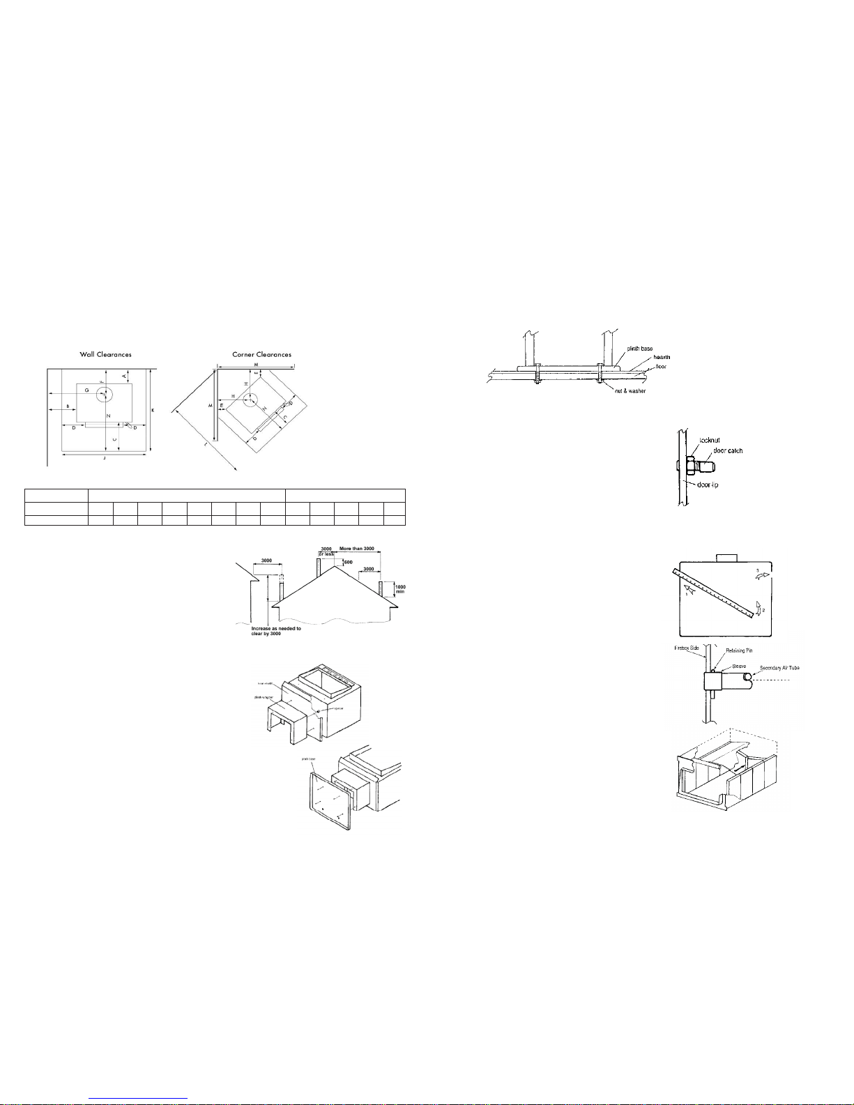
Minimum Installation Clearances
Hearth Clearances
(mm)
A B C D E F G H J K L M N
With flue shield
75
300
300
200
150
260
565
457
890
1120
1350
1000
760
FLUE SYSTEMS
The flue system should be vertical and without bends. If an offset is req uired, it should be as close to the heater as practicable and
should not be offset more than 500mm from the centreline of the flue stub. Clearances from the flue pipe to combustible materials
must be maintained (refer Table 1 and Fig 1). Restrictions or leaks in the flue system may reduce the draught, and, in severe
conditions, could cause smoke to enter the room. The flue pipe shall extend not less than 4.6m above the top of the floor protector.
The flue cowl must be at least 600mm above the highest point of the roof if within 3 metres of it, or 1000mm above the roof
penetration if more than 3 metres from the ridge. No part of the building, or any adjacent building may be in, or above, a circular
area of a horizontal radius of 3 metres from the flue exit (Fig 2 *).
SEISMIC RESTRAINT
The heater must be restrained against movement due to earthquakes. The Tilefire is restrained by fixing the heater to the floor with
two b olts of 6mm diameter through the holes provided in the plinth base, through the hearth and floor and fixed with heavy
washers and nuts. For solid concrete floors, use 8mm DYNABOLTS® or similar with a minimum depth of engagement into the floor of
50mm. Location of fixing bolts (Refer Fig. 5)
Fig 5
DOOR HANDLE AND DOOR
Table 1
* These heights are given as a general minimum, and in actual
practice the presence of surrounding structures, trees, fences, etc.
may necessitate additional height for satisfactory performance. The
cowl must be fitted to prevent entry of birds, snow and rain.
At all flue joints, the swaged end of the upper piece must be fitted to
the plain end of the lower piece.
FLOOR PROTECTOR
An insulating floor protector is not required for the Tilefir e heater, but a
floor protector of non-combustible material must be used. The floor
protector must extend under the heater, a minimum of 300mm in front
of the door opening, and 180mm to either side of the heater. The
minimum floor protector size for a wall installation is 890mm wide and
1120mm front to back, excluding trim. For a corner installation the
minimum length along the wall is 1000mm and diagonally from the
corner to the front edge is 1350mm, also excluding trim.
ASSEMBLY
The Tilefire is supplied with additional component packs that contain
the ash spill tray, fire bricks, baffle and air tube and plinth.
Before starting assembly, please unpack these and familiarise yourself
with the components as you read these instructions.
CAUTION: when lifting the heater, always lift from under the cabinet
outer surround. DO NOT LIFT from the door, ash spill tray or front air slide
as these will be damaged.
Begin assembly by laying the heater carefully on its back on a padded
surface. Place the 4 coach-bolts from the bolt pack through the holes in
the floor of the firebox from inside and screw on the hexagonal spacer
nuts. Place the heat-shield onto the bolts with the turned up edge
facing the door frame. Fit the plinth wrapper onto the bolts and fix in
place with lock washers and nuts. Note that the open side of the plinth
wrapper mu st face to the rear of the heater (Refer Fig. 3). Screw the
plinth base to the wrapper using 4 screws provided (Refer Fig. 4). Place
the heater back onto its base, taking care to lift the heater, not roll it, to
avoid damage to components.
Fig 3
Fig 4
Fig 2
The door handle is pre-fitted and should not require any adjustment
on assembly of the heater. Any adjustment required to maintain the
correct fit of the door is made at the door catch pin on the right side
of the door lip. To adjust the fit of the door catch, loosen th e lock nut
and turn the eccentric pin to loosen or tighten the fit. Re-tighten the
lock nut (refer Fig. 6).
AIR CONTROL KNOB
The air control knob is fitted to the stem with a grub-screw to retain it.
If this requires replacing, it will be necessary to loosen this screw before
pulling off the knob. Refit the knob by lining up the flats in the knob
with the flats on the stem and pushing home. Tighten the grub-screw.
ASH SPILL TRAY
Fit the ash spill tray under the door opening by placing the hex head
bolts through the two holes u nder the door lip, from inside the firebox,
and screw them into the two captive nuts i n the back face of the ash
spill tray.
FIREBRICKS, BAFFLE PLATE AND AIR TUBE
Fit the secondary air tube, if not already fitted. The tube has a notch in
one end - this is the right hand end. Slide the sleeve from the
component pack onto the tube. Place the tube into the firebox and
insert the left end into the hole in the left side of the firebox. Lift the
right end up and slide it into the hole in the right side of the firebox,
rotating it to allow the notch to fit over the tab in the hole (refer Fig. 7).
Slide the sleeve to the left until it en ters the hole in the left side of the
firebox, and retain it with the pin supplied. The pin should pass
completely through the sleeve and air tube. Note that the sleeve
should not project outside the firebox. If necessary, reverse the sleeve
on the air tube (refer Fig. 8).
The brick pack comprises 8 bricks 280mm x 115mm x 25mm, and two
bricks 250mm x 188mm x 25mm. Place the baffle plate into the firebox
and hold up against the roof while 4 bricks are placed on end on
either side of the firebox. Note that the baffle is placed with the
concave surface down. Lower the baffle plate down onto the bricks
so the tops of the bricks are retained behind the angles on either side
of the plate. Fit the two remaining wide bricks on end across the back
of the firebox. It may be necessary to fit these by putting the two outer
edges of the bricks into position against the side bricks and then
pushing both inner edges back at the same time like a folding door
(refer Fig. 9). Ensure the baffle plate is pu shed hard against the back
wall of the firebox.
Fig 6
Fig 7
Fig 8
Fig 9
Fig 1
 Loading...