

KENT razor blade 26D, razor blade 28D, 908 7101 020, razor blade 28C, 908 7099 020 Service Manual
...Page 1

Simple. Clean.
Razor Blade 26D/28D/28C
SERVICE MANUAL
Kent models:
908 7099 020 - 908 7100 020 - 908 7101 020
909 6510 000(3) 2007-12
Page 2

Page 3

SERVICE MANUAL
ENGLISH
Razor Blade 26D / 28D / 28C 909 6510 000(3)2007-12
1
TABLE OF CONTENTS
GENERAL INFORMATION .............................................................................................................................................. 3
CONVENTIONS .............................................................................................................................................................................. 3
MACHINE LIFTING ......................................................................................................................................................................... 3
MACHINE TRANSPORTATION ....................................................................................................................................................... 3
OTHER AVAILABLE MANUALS ...................................................................................................................................................... 3
SAFETY ........................................................................................................................................................................................... 4
SYMBOLS ....................................................................................................................................................................................... 4
GENERAL SAFETY PRECAUTIONS .............................................................................................................................................. 4
TECHNICAL DATA ........................................................................................................................................................................... 6
MAINTENANCE ............................................................................................................................................................... 8
SCHEDULED MAINTENANCE ....................................................................................................................................................... 8
SCHEDULED MAINTENANCE TABLE ........................................................................................................................................... 8
MACHINE NOMENCLATURE ......................................................................................................................................................... 9
DETERGENT SUPPLY SYSTEM................................................................................................................................... 13
SOLUTION/WASHING WATER SYSTEM AND TANK CLEANING ............................................................................................... 13
SOLUTION/WASHING WATER FILTER CLEANING .................................................................................................................... 13
SOLUTION/WASHING WATER SYSTEM SOLENOID VALVE/TAP/FILTER DISASSEMBLY/ASSEMBLY .................................. 14
TROUBLESHOOTING ................................................................................................................................................................... 16
BRUSHING SYSTEM ..................................................................................................................................................... 17
BRUSH/CYLINDRICAL BRUSH CLEANING ................................................................................................................................. 17
SIDE SKIRT CHECK (AND REPLACEMENT) .............................................................................................................................. 17
BRUSH/PAD-HOLDER DECK OR CYLINDRICAL BRUSH DECK DISASSEMBLY/ASSEMBLY ................................................. 18
BRUSH MOTOR ELECTRICAL INPUT CHECK ............................................................................................................................ 18
BRUSH MOTOR CARBON BRUSH CHECK AND REPLACEMENT ............................................................................................ 20
BRUSH/PAD-HOLDER MOTOR DISASSEMBLY/ASSEMBLY ..................................................................................................... 21
CHECK/REPLACEMENT/ADJUSTMENT OF DRIVING BELTS BETWEEN MOTORS AND CYLINDRICAL BRUSHES ............ 24
BRUSH DECK LIFTING/LOWERING ACTUATOR DISASSEMBLY/ASSEMBLY ......................................................................... 26
TROUBLESHOOTING ................................................................................................................................................................... 28
RECOVERY WATER SYSTEM ...................................................................................................................................... 29
RECOVERY WATER TANK AND VACUUM GRID AUTOMATIC SHUT-OFF FLOAT CLEANING ................................................ 29
VACUUM SYSTEM MOTOR ELECTRICAL INPUT CHECK ......................................................................................................... 30
VACUUM SYSTEM MOTOR CARBON BRUSH CHECK AND REPLACEMENT .........................................................................31
VACUUM SYSTEM MOTOR DISASSEMBLY/ASSEMBLY ........................................................................................................... 32
SQUEEGEE CLEANING/CHECK AND BLADE REPLACEMENT.................................................................................................33
SQUEEGEE LIFTING CABLE SLIDING SHOE LUBRICATION....................................................................................................34
SQUEEGEE LIFTING ACTUATOR DISASSEMBLY/ASSEMBLY ................................................................................................. 35
SQUEEGEE LIFTING CABLE DISASSEMBLY/ASSEMBLY ......................................................................................................... 36
TROUBLESHOOTING ................................................................................................................................................................... 37
Page 4

ENGLISH
SERVICE MANUAL
2
909 6510 000(3)2007-12 Razor Blade 26D / 28D / 28C
TABLE OF CONTENTS
PARKING BRAKE SYSTEM .......................................................................................................................................... 38
PARKING BRAKE CHECK ............................................................................................................................................................ 38
ELECTROMAGNETIC BRAKE DISASSEMBLY/ASSEMBLY (Machines up to January 2007) ..................................................... 39
ELECTROMAGNETIC BRAKE AND DISC WITH BRAKING MASSES DISASSEMBLY/ASSEMBLY
(Machines after January 2007) ...................................................................................................................................................... 41
TROUBLESHOOTING ................................................................................................................................................................... 43
DRIVE SYSTEM ............................................................................................................................................................. 44
DRIVING WHEEL COVER DISASSEMBLY/ASSEMBLY (Machines up to January 2007) ............................................................ 44
DRIVING WHEEL COVER DISASSEMBLY/ASSEMBLY (Machines after January 2007) ............................................................ 45
DRIVE SYSTEM MOTOR ELECTRICAL INPUT CHECK (Machines up to January 2007) ........................................................... 47
DRIVE SYSTEM MOTOR ELECTRICAL INPUT CHECK (Machines after January 2007)............................................................48
DRIVE SYSTEM MOTOR CARBON BRUSH CHECK AND REPLACEMENT (Machines up to January 2007) ........................... 49
DRIVE SYSTEM MOTOR CARBON BRUSH CHECK AND REPLACEMENT (Machines after January 2007) ............................ 50
DRIVE SYSTEM MOTOR SLIDING CONTACT CHECK AND REPLACEMENT (Machines after January 2007)......................... 51
DRIVE SYSTEM MOTOR DISASSEMBLY/ASSEMBLY (Machines up to January 2007) ............................................................. 53
DRIVE SYSTEM MOTOR, BEARING AND GASKET DISASSEMBLY/ASSEMBLY (Machines after January 2007) .................... 54
FORWARD/REVERSE GEAR PEDAL DISASSEMBLY/ASSEMBLY ............................................................................................ 57
FORWARD/REVERSE GEAR PEDAL POTENTIOMETER CHECK AND ADJUSTMENT ........................................................... 58
SPEED REDUCTION SENSOR CHECK/ADJUSTMENT ............................................................................................................. 59
SPEED REDUCTION SENSOR REPLACEMENT ........................................................................................................................ 60
DRIVER'S SEAT SAFETY MICROSWITCH OPERATION CHECK .............................................................................................. 62
DRIVER'S SEAT SAFETY MICROSWITCH REPLACEMENT ...................................................................................................... 62
TROUBLESHOOTING ................................................................................................................................................................... 63
OTHER SYSTEMS ......................................................................................................................................................... 65
SCREW AND NUT TIGHTENING CHECK .................................................................................................................................... 65
FRONT FAIRING DISASSEMBLY/ASSEMBLY ............................................................................................................................. 66
ELECTRICAL SYSTEM ................................................................................................................................................. 68
MACHINE WORKING HOUR CHECK .......................................................................................................................................... 68
HOUR COUNTER RESET PROCEDURE ..................................................................................................................................... 68
BATTERY MAINTENANCE AND RECHARGING .......................................................................................................................... 68
BATTERY DISASSEMBLY/ASSEMBLY ........................................................................................................................................ 68
FUSE CHECK/REPLACEMENT .................................................................................................................................................... 69
DRIVE SYSTEM ELECTRONIC BOARD REPLACEMENT .......................................................................................................... 70
FUNCTION ELECTRONIC BOARD REPLACEMENT .................................................................................................................. 71
DASHBOARD ELECTRONIC BOARD REPLACEMENT .............................................................................................................. 72
TROUBLESHOOTING ................................................................................................................................................................... 73
FUNCTION ELECTRONIC BOARD ERROR CODES .................................................................................................................. 73
COMPONENT LAYOUT ................................................................................................................................................................ 78
WIRING DIAGRAM ........................................................................................................................................................................ 81
Page 5

SERVICE MANUAL
ENGLISH
Razor Blade 26D / 28D / 28C 909 6510 000(3)2007-12
3
GENERAL INFORMATION
GENERAL INFORMATION
CONVENTIONS
Forward, backward, front, rear, left or right are intended with reference to the operator’s position, that is to say in driving position.
MACHINE LIFTING
WARNING!
Do not work under the lifted machine without supporting it with safety stands.
MACHINE TRANSPORTATION
WARNING!
Before transporting the machine, make sure that:
All doors and cases are closed.
The ignition key is removed.
The machine is securely fastened to the means of transport.
–
–
–
OTHER AVAILABLE MANUALS
The following manuals are available at Kent Literature Service Department:
RAZOR BLADE Instructions for Use Manual 26D-28D-28C – 909 6457 000
RAZOR BLADE Spare Parts List 26D-28D-28C – 909 6458 000
–
–
Page 6

ENGLISH
SERVICE MANUAL
4
909 6510 000(3)2007-12 Razor Blade 26D / 28D / 28C
GENERAL INFORMATION
SAFETY
The following symbols indicate potentially dangerous situations. Always read this information carefully and take all necessary
precautions to safeguard people and property.
SYMBOLS
DANGER!
It indicates a dangerous situation with risk of death for the operator.
WARNING!
It indicates a potential risk of injury for people or damage to objects.
CAUTION!
It indicates a caution or a remark related to important or useful functions. Pay careful attention to the
paragraphs marked by this symbol.
NOTE
It indicates a remark related to important or useful functions.
CONSULTATION
It indicates the necessity to refer to the User Manual before performing any procedure.
GENERAL SAFETY PRECAUTIONS
Specic warnings and cautions to inform about potential damages to people and machine are shown below.
DANGER!
Before performing any maintenance/repair procedure drive the machine on a level ground, remove the
ignition key and disconnect the battery.
This machine must be used by properly trained and authorized personnel only.
Keep the battery away from sparks, ames and incandescent material. During the normal operation,
explosive gases are released.
Do not wear jewelry when working near electrical components.
Do not work under the lifted machine without supporting it with safety stands.
Do not operate the machine near toxic, dangerous, ammable and/or explosive powders, liquids or vapors.
Battery charging produces highly explosive hydrogen gas. Keep the tanks open during battery charging
and perform this procedure in well-ventilated areas and away from naked ames.
–
–
–
–
–
–
–
Page 7

SERVICE MANUAL
ENGLISH
Razor Blade 26D / 28D / 28C 909 6510 000(3)2007-12
5
GENERAL INFORMATION
GENERAL SAFETY PRECAUTIONS (Continues)
WARNING!
Carefully read all the instructions before carrying out any maintenance/repair procedure.
Before using the battery charger, ensure that frequency and voltage values, indicated on the machine serial
number plate, match the electrical mains voltage.
To reduce the risk of re, electric shock, or injury, do not leave the machine unattended when it is plugged
in. Unplug the machine from the electrical mains when not in use and before performing maintenance
procedures.
To avoid electric shock, do not expose to rain. Store the machine indoors.
Do not allow to be used as a toy. Close attention is necessary when used near children.
Use only as described in this Manual. Use only Kent’s recommended accessories.
Do not use with damaged power supply cable or plug. If the machine is not working as it should, has been
damaged, left outdoors or dropped into water, return it to the Service Center.
Do not pull or carry the machine by the supply cable; never use the power supply cable as a handle. Do not
close a door on the supply cable, or pull the supply cable around sharp edges or corners. Do not run the
machine on the supply cable.
Keep the power supply cable away from heated surfaces.
Take all necessary precautions to prevent hair, jewelry and loose clothes from being caught by the machine
moving parts.
Do not smoke while charging the batteries.
Do not leave the machine unattended with the ignition key inserted and without being sure that it cannot
move independently.
Do not use the machine on slopes with a gradient exceeding the specications.
Do not wash the machine with direct or pressurised water jets, or with corrosive substances.
Do not use the machine in particularly dusty areas.
While using this machine, take care not to cause damage to people or objects.
The machine storage temperature must be between +32°F and +104°F (0°C and +40°C).
The machine operating temperature must be between +32°F and +104°F (0°C and +40°C).
The humidity must be between 30% and 95%.
Always protect the machine against the sun, rain and bad weather, both under operation and inactivity
condition.
Do not use the machine as a means of transport.
Do not use the machine on slopes with a gradient exceeding the specications.
Do not allow the brushes to operate while the machine is stationary to avoid damaging the oor.
In case of re, use a powder re extinguisher, not a water one.
Do not bump into shelves or scaffoldings, particularly where there is a risk of falling objects.
Do not remove or modify the plates afxed to the machine.
If parts must be replaced, require ORIGINAL spare parts from a Dealer or Authorised Retailer.
The machine must be disposed of properly, because of the presence of toxic-harmful materials (batteries,
etc.), which are subject to standards that require disposal in special centers (see Scrapping chapter in the
User Manual).
Do not allow any object to enter into the openings. Do not use the machine if the openings are clogged.
Always keep the openings free from dust, hairs and any other foreign material which could reduce the air
ow.
This machine cannot be used on roads or public streets.
Pay attention during machine transport when temperature is below freezing point. The water in the recovery
tank or in the hoses could freeze and seriously damage the machine.
Use brushes and pads supplied with the machine and those specied in the User Manual. Using other
brushes or pads could reduce safety.
–
–
–
–
–
–
–
–
–
–
–
–
–
–
–
–
–
–
–
–
–
–
–
–
–
–
–
–
–
–
–
–
Page 8

ENGLISH
SERVICE MANUAL
6
909 6510 000(3)2007-12 Razor Blade 26D / 28D / 28C
GENERAL INFORMATION
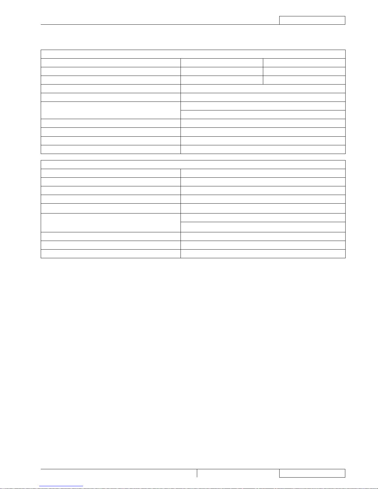
TECHNICAL DATA
GENERAL TECHNICAL DATA
Description 26D 28D - 28C
Cleaning width 26.0 in (660 mm) 29.1 in (740 mm)
Squeegee width 32.7 in (830 mm) 33.9 in (860 mm)
Solution tank capacity 20 gal (75 liters)
Recovery water tank capacity 20 gal (75 liters)
Min/max solution ow 0,29 - 0,9 gal/min (1,1 - 3,4 litres/min)
Solution/clean water autonomy 0,29 gal/min (1,1 litres/min): ~ 68 min Media/Average
Rear wheel diameter (on xed axle) 11.8 in (300 mm)
Wheel specic pressure on the oor (*) front116 psi (0.8 N/mm2) - rear 145 psi (1.0 N/mm2)
Front steering, driving and braking wheel diameter 9.8 in (250 mm)
Minimum turning radius 40,5 in (1030 mm)
Vacuum system motor power 0.68 hp (500 W)
Drive system motor power 0.80 hp (600 W)
Drive speed (variable) 0 to 3.7 mph (0 to 6 km/h)
Max gradeability 16% (7,2°)
Working gradeability 2% (1°)
Sound pressure level at the operator’s position
(ISO 11201, ISO 4871) (LpA)
60,8 dB(A) ± 3dB(A)
Sound pressure level to the machine
(ISO 3744, ISO 4871) (LwA)
82,4 dB(A)
Vibration level at the operator’s arms (ISO 5349-1) (**) 9.05 - 295.27 in/s2 (0.23 – 7.5 m/s2)
Vibration level at the operator’s body (ISO 2631-1) (**) < 47.24 in/s2 (1.2 m/s2)
Batteries
24 V battery box, 240 Ah/5 h (WET) 240 Ah C5
24 V battery box, 240 Ah/5 h (GEL) (optional) 240 Ah C5
4 6 V batteries, 180 Ah/5 h (WET) 180 Ah C5
4 6 V batteries, 180 Ah/5 h (GEL) (optional) 180 Ah C5
Standard batteries autonomy ~ 3 h
Maximum battery compartment size
24 V battery box: 14.0 x 23.9 x 14.6 in (355 x 606 x 370 mm)
4 6 V batteries, with case: 20.8 x 15.0 x 11.8 in (530 x 380 x 300 mm)
Total consumption in work condition 62 A
Vacuum system capacity 1,76 MPa (1,800 mm H2O)
Machine height 49.2 in (1,250 mm)
Machine maximum length 57.0 in (1,450 mm)
Machine width without squeegee 26.8 in (681.5 mm) 30.0 in (758 mm)
(*) Machine test have been performed under the following conditions:
with operator [165.3 lb (75 kg)] if ride-on
Battery maximum size
Brush and squeegee maximum size
Full solution tank
Optional equipment installed
Wheel weight checked
Each wheel print checked on cement
Result expressed as maximum value for both front and rear wheels
(**) Under normal working conditions, on a level asphalt surface.
•
•
•
•
•
•
•
•
Page 9
SERVICE MANUAL
ENGLISH
Razor Blade 26D / 28D / 28C 909 6510 000(3)2007-12
7
GENERAL INFORMATION
TECHNICAL DATA (Continues)
TECHNICAL DATA FOR MACHINES WITH BRUSH/PAD-HOLDER DECK
Description 26D 28D
Brush diameter 13.0 in (330 mm) 14.5 in (370 mm)
Deck right/left offset 3,4/1,8 in (87,8/46,8 mm) 4,6/3 in (117,4/76,7 mm)
Brush distance from the ground (when lifted) 3,7 in (95,5 mm)
Weight without batteries and with empty tanks 308 lb (140 kg)
Maximum weight with batteries and full tanks
With 4 6 V batteries: 849 lb (385 kg)
With 24 V battery box: 1,036 lb (470 kg)
Brush/pad-holder motor power 0.54 hp (400 W)
Brush/pad-holder rotation speed 190 rpm
Brush/pad-holder pressure with extra-pressure deactivated 66 lb (30 kg)
Brush/pad-holder pressure with extra-pressure activated 110 lb (50 kg)
TECHNICAL DATA FOR MACHINES WITH CYLINDRICAL BRUSH DECK
Description 28C
Cylindrical brush size (diameter x length) 5.7 x 27.1 in (145 x 690 mm)
Deck right/left offset 5,5/3,6 in (138,7/92,2 mm)
Brush distance from the ground (when lifted) 1,8 in (45,5 mm)
Weight without batteries and with empty tanks
308 lb (140 kg)
Maximum weight with batteries and full tanks
With 4 6 V batteries: 849 lb (385 kg)
With 24 V battery box: 1,036 lb (470 kg)
Cylindrical brush motor power 0.81 hp (600 W)
Cylindrical brush rotation speed 748 rpm
Cylindrical brush pressure 73.48 lb (33.4 kg)
Page 10
ENGLISH
SERVICE MANUAL
8
909 6510 000(3)2007-12 Razor Blade 26D / 28D / 28C
GENERAL INFORMATION
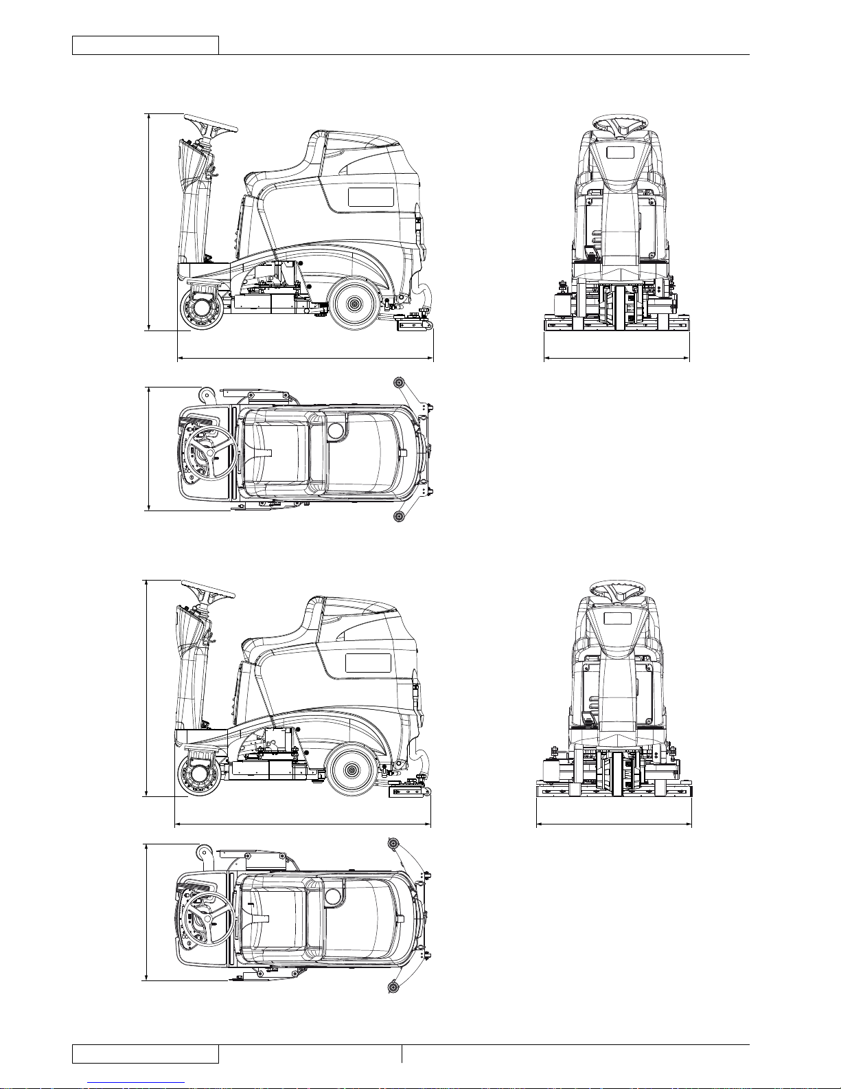
DIMENSIONS RAZOR BLADE 26D
681.5 mm (26.8 in)
830 mm (32.6 in)1450 mm (57.0 in)
1250 mm (49.2 in)
DIMENSIONS RAZOR BLADE 28D
758 mm (30 in)
1450 mm (57.0 in)
1250 mm (49.2 in)
860 mm (33.9 in)
Page 11
SERVICE MANUAL
ENGLISH
Razor Blade 26D / 28D / 28C 909 6510 000(3)2007-12
9
GENERAL INFORMATION
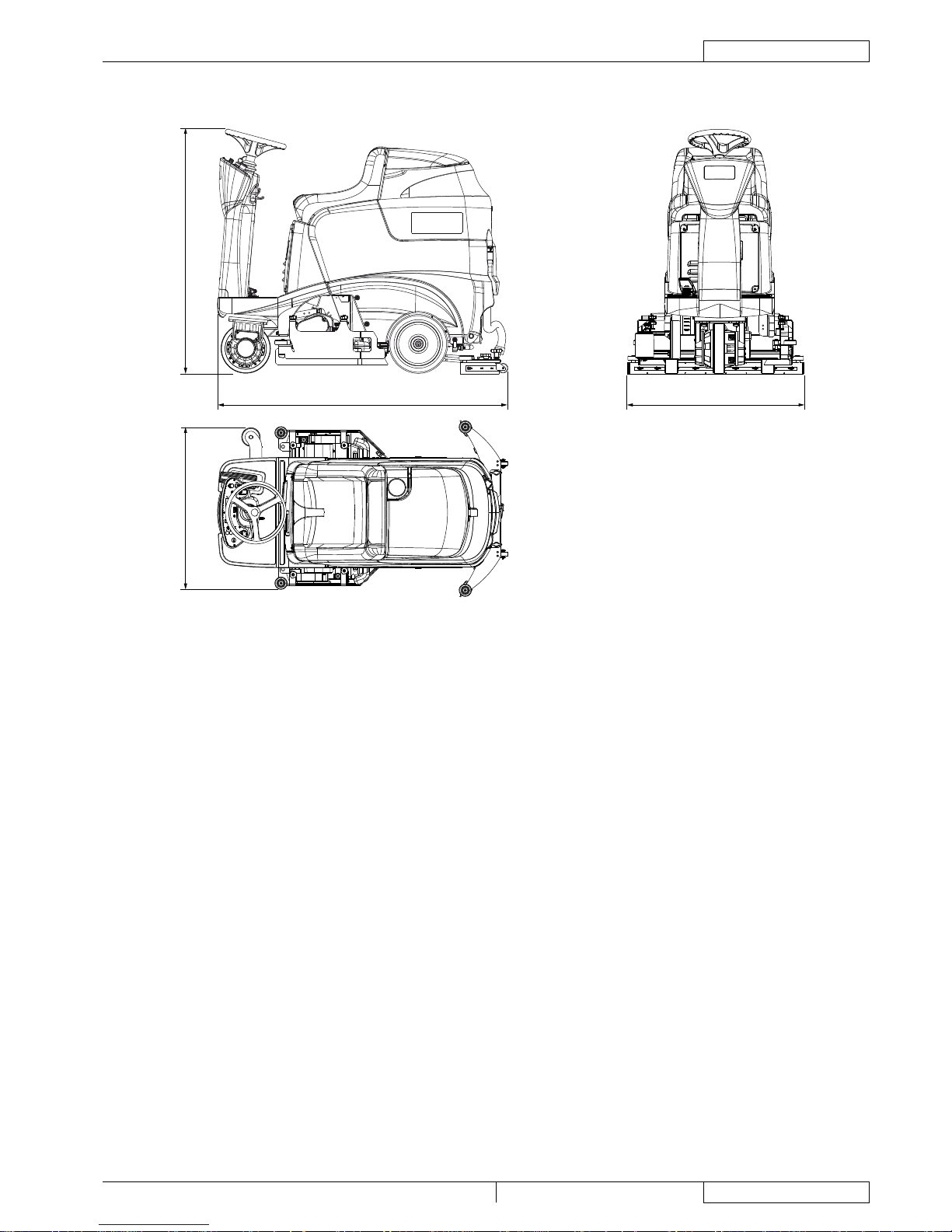
DIMENSIONS RAZOR BLADE 28C
758 mm (30 in)
1450 mm (57.0 in)
1250 mm (49.2 in)
860 mm (33.9 in)
Page 12
ENGLISH
SERVICE MANUAL
10
909 6510 000(3)2007-12 Razor Blade 26D / 28D / 28C
MAINTENANCE
MAINTENANCE
SCHEDULED MAINTENANCE
The lifespan of the machine and its maximum operating safety are ensured by correct and regular maintenance.
WARNING!
See the GENERAL INFORMATION and SAFETY paragraphs.
The following table provides the scheduled maintenance. The intervals shown may vary according to particular working conditions,
which are to be dened by the person in charge of the maintenance.
For instructions on maintenance procedures, see the following paragraphs.
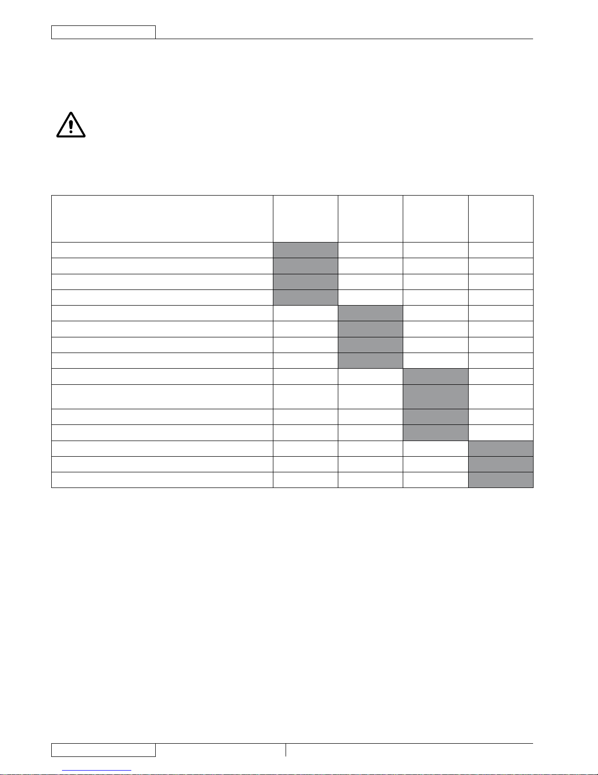
SCHEDULED MAINTENANCE TABLE
Procedure
Daily, after
machine use
Weekly
Every six
months
Yearly
Squeegee cleaning
Brush cleaning
Tank and vacuum grid with oat cleaning
Battery charging
Squeegee blade check and replacement
Side skirt check
Solution lter cleaning
WET battery uid level check
Screw and nut tightening check (1)
Check and adjustment of driving belts between motors and
cylindrical brushes
Squeegee cable sliding shoe lubrication
Electromagnetic parking brake efciency check
Brush/pad-holder motor carbon brush check or replacement
Vacuum system motor carbon brush check or replacement
Drive system motor carbon brush check or replacement
(1) And after the rst 8 working hours.
Page 13

SERVICE MANUAL
ENGLISH
Razor Blade 26D / 28D / 28C 909 6510 000(3)2007-12
11
MAINTENANCE
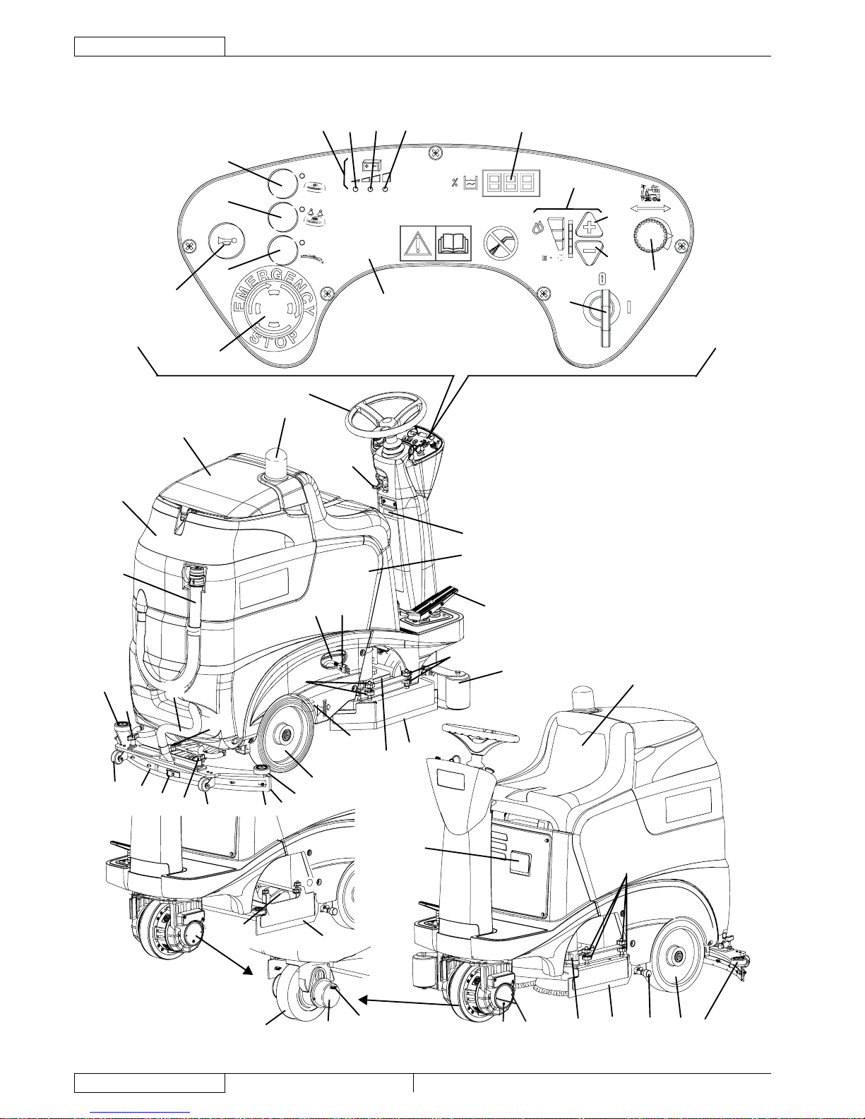
Control panel
Emergency push-button
Horn
Brush/pad-holder deck and cylindrical brush deck lifting/
lowering switch
Brush/pad-holder extra-pressure switch. With the
cylindrical brush deck installed, this switch is disabled.
Squeegee lifting/lowering and vacuum system on/off switch
Battery charge indicator
7a. Charged battery warning light (green)
7b. Semi-discharged battery warning light (yellow)
7c. Discharged battery warning light (red)
Hour counter and solution level display:
When the machine is started, it displays for a few
seconds the number of working hours which have been
performed.
While using the machine, it displays the solution level
in the tank (measured in percentage terms, compared
with the full tank). When the level is below 20%, the
display starts blinking. The display could indicate
“000 %” even if the tank is not completely empty, thus
allowing to complete the cleaning cycle; in any case,
it is recommended to check the actual solution ow
supplied to the brushes.
Solution ow control switches
10a. Flow increase switch
10b. Flow decrease switch
Maximum speed adjuster (enabled only when the brushes
are operating)
Ignition key
Steering wheel tilting control lever
Steering wheel
Forward/reverse gear pedal
Brush/pad-holder deck
Cylindrical brush deck
Side skirts
Battery charger cable housing
Battery charger cable
Solution lter
Recovery water drain hose
Squeegee vacuum hose
Squeegee
Bumper wheels
Squeegee support wheels
Squeegee mounting handwheels
Squeegee balance adjusting handwheel
Front squeegee blade
Rear squeegee blade
Squeegee rear blade fastening hook
Solution tank
Recovery water tank
Recovery water tank cover
Flashing light (optional)
Solution tap
Seat
Battery charger
Electromagnetic parking brake
Front steering, driving and braking wheel
41a. Electromagnetic brake unlock handwheel (*)
41b. Electromagnetic brake unlock handwheel (**)
Serial number plate/technical data
Rear wheels
1.
2.
3.
4.
5.
6.
7.
8.
•
•
10.
11.
12.
13.
14.
15.
16.
17.
18.
19.
20.
21.
22.
23.
24.
25.
26.
27.
28.
29.
30.
31.
32.
33.
34.
35.
36.
37.
38.
39.
40.
42.
43.
Side skirt height adjustment knobs
Recovery water tank cover (open)
Recovery water tank cover gasket
Recovery water vacuum duct
Vacuum grid with automatic shut-off oat
Float
Grid fasteners
Solution tank ller neck
Solution tank cover
Cover support rod
Recovery water tank
Solution tank
Tank assembly (open)
Batteries
Battery case
Battery connector
Battery caps
Battery connection diagrams
Brush/pad-holder deck
Brush/pad-holder motors
Brush/pad-holder deck or cylindrical brush deck connector
Solution hose
Deck mounting knob
Deck fastening cotter pins
Deck support
Brush
Pad-holder
Pad
Cylindrical brush deck connector
Connector protection cover
Brush/pad-holder deck side skirt
Cylindrical brush deck
Cylindrical brush motors
Cylindrical brush deck side skirt
Skirt upper mounting knob
Skirt lower mounting knob
Cylindrical brush
Cylindrical brush lids
Lid mounting knobs
Cylindrical brush debris container
Debris container handle
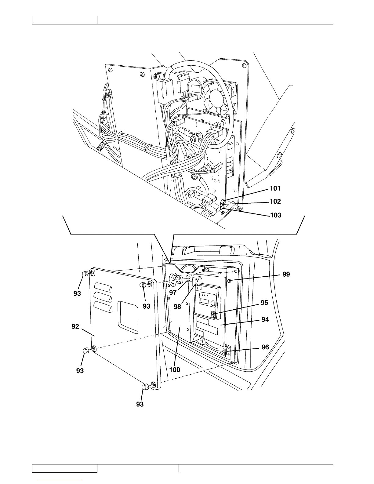
Electrical component cover
Cover mounting nuts
Battery charger
Battery type selector (“WET” or “GEL”)
Drive system electronic board protection fuse (F2) (60 A)
Low power circuit protection fuse (F3) (5 A)
Function electronic board protection fuse (F1) (100 A)
Warning LED
Electrical component panel
Red LED (upper)
Green LED
Red LED (lower)
(*) Machines up to January 2007
(**) Machines after January 2007
44.
45.
46.
47.
48.
49.
50.
51.
56.
57.
58.
59.
60.
61.
62.
63.
64.
65.
69.
70.
71.
72.
73.
74.
75.
76.
77.
78.
79.
80.
81.
82.
83.
84.
85.
86.
87.
88.
89.
90.
91.
92.
93.
94.
95.
96.
97.
98.
99.
100.
101.
102.
103.
MACHINE NOMENCLATURE
Throughout this Manual you will nd numbers in brackets – for example: (2). These numbers refer to the components shown in the
nomenclature pages. Refer to these pages whenever it is required to identify a component mentioned in the text.
Page 14
ENGLISH
SERVICE MANUAL
12
909 6510 000(3)2007-12 Razor Blade 26D / 28D / 28C
MAINTENANCE
MACHINE NOMENCLATURE (Continues)
33
34
35
13
14
42
32
15
19
20
25
18
16
21
43
25
29
30
27
31
24
26
26
27
25
23
28
17
18
37
38
16
18 36
43
25
22
44
44
44
3
2
6
5
4
7
7c
7b
7a
8
10
10a
10b
11
12
1
40
39
41a
39
41b
S301315
Page 15

SERVICE MANUAL
ENGLISH
Razor Blade 26D / 28D / 28C 909 6510 000(3)2007-12
13
MAINTENANCE
MACHINE NOMENCLATURE (Continues)
S301396
S301397
S301318
Page 16
ENGLISH
SERVICE MANUAL
14
909 6510 000(3)2007-12 Razor Blade 26D / 28D / 28C
MAINTENANCE
MACHINE NOMENCLATURE (Continues)
S301619
Page 17
SERVICE MANUAL
ENGLISH
Razor Blade 26D / 28D / 28C 909 6510 000(3)2007-12
15
DETERGENT SUPPLY SYSTEM
DETERGENT SUPPLY SYSTEM
SOLUTION TANK CLEANING
Drive the machine to the appointed disposal and washing area.
Turn the ignition key (12) to "0".
Empty the solution tank (59) with the tap (36).
Start the machine (as shown in the User Manual) and keep it running until the solution tank is completely empty.
Open the cover (56) and install the support rod (57).
Clean and wash with clean water the cover (56), the tank (59) and the ller (51).
Drain the water in the tank with the tap (36).
Start the machine (as shown in the User Manual) and keep it running until the solution tank is completely empty.
Remove the support rod (57) and close the cover (56).
Clean the solution lter (see the following procedure).
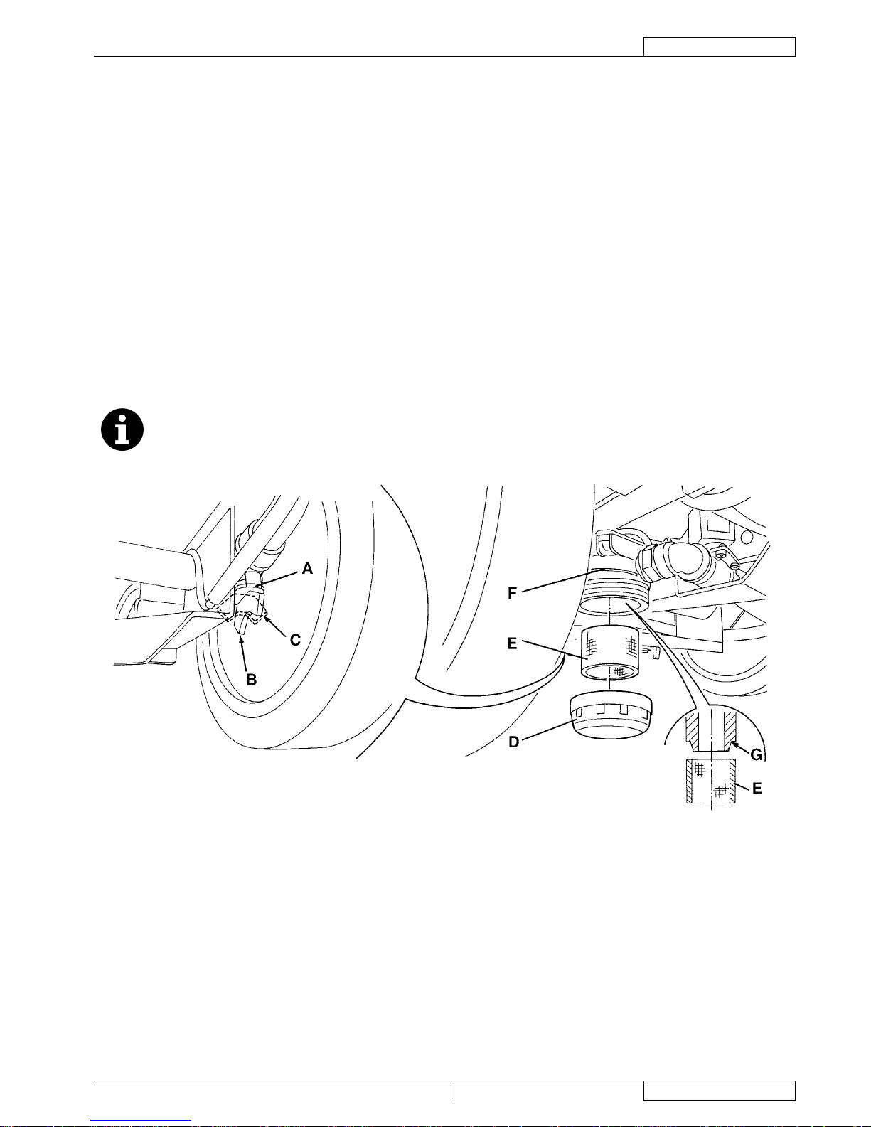
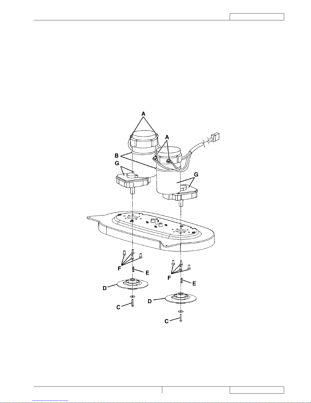
SOLUTION FILTER CLEANING
Drive the machine on a level oor.
Turn the ignition key (12) to "0".
Close the solution tap (A) under the machine, behind the right rear wheel. The tap (A) is closed when it is in the position (B)
and it is open when it is in the position (C).
Remove the transparent cover (D), then remove the lter strainer (E) under the machine, in front of the right rear wheel. Clean
and install them on the support (F).
NOTE
The lter strainer (E) must be correctly positioned on the housing (G) of the support (F).
Open the tap (A).
S301320
1.
2.
3.
4.
5.
6.
7.
8.
9.
10.
1.
2.
3.
4.
5.
Page 18

ENGLISH
SERVICE MANUAL
16
909 6510 000(3)2007-12 Razor Blade 26D / 28D / 28C
DETERGENT SUPPLY SYSTEM
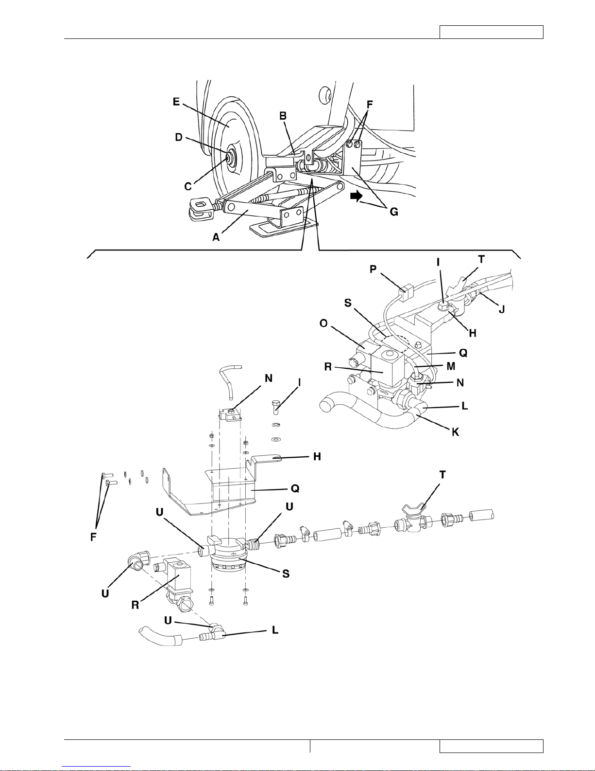
SOLUTION SYSTEM SOLENOID VALVE/TAP/FILTER DISASSEMBLY/ASSEMBLY
Disassembly
Drive the machine to the appointed disposal area, and empty the recovery water tank (58) with the hose (22).
Empty the solution tank (59) with the tap (36).
Place the machine on a hoisting system (if available), then lift it. Otherwise, drive the machine on a level oor.
Turn the ignition key (12) to "0".
Place a suitable jack (A) under the machine right side bracket (B).
Lift the machine for 0.78 in (2 cm) with the jack.
Remove the screw (C) and recover the washer (D).
Remove the right wheel (E).
Remove the screws (F).
Move the support (G) forward, by disengaging the fastener (H) from the screw (I).
Disconnect the hoses (J) and (K) from their ttings (L).
Disconnect the hose (M) from the pressure switch (N) by pulling it.
Disconnect the connectors (O) of the solenoid valve (P) and of the pressure switch.
Recover the whole assembly (G) and, at the workbench, remove the solenoid valve (R), or the lter assembly (S), or the tap
(T), by disconnecting/unscrewing the connecting/fastening components.
Assembly
Assemble the components in the reverse order of disassembly, and note the following:
Before screwing the threaded ttings (U) clean them, then apply Teon tape, according to the screwing direction;
when assembling the solenoid valve (R), the stamped arrow must be tuned in the direction of the solution ow.
1.
2.
3.
4.
5.
6.
7.
8.
9.
10.
11.
12.
13.
14.
15.
•
•
Page 19
SERVICE MANUAL
ENGLISH
Razor Blade 26D / 28D / 28C 909 6510 000(3)2007-12
17
DETERGENT SUPPLY SYSTEM
SOLUTION SYSTEM SOLENOID VALVE/TAP/FILTER DISASSEMBLY/ASSEMBLY (Continues)
S301321
Page 20

ENGLISH
SERVICE MANUAL
18
909 6510 000(3)2007-12 Razor Blade 26D / 28D / 28C
DETERGENT SUPPLY SYSTEM
TROUBLESHOOTING
SMALL AMOUNT OF SOLUTION OR NO SOLUTION REACHES THE BRUSH
Possible causes:
The solution lter is clogged/dirty (clean).
The solution tap is closed/semi-closed (replace).
The solenoid valve is broken or there is an open in the electrical connection (replace the solenoid valve/repair the electrical
connection).
There is debris in the solution tank clogging the output hole (clean the tank).
There are debris in the solution hoses clogging the ow (clean the hoses).
THE SOLUTION REACHES THE BRUSH ALSO WHEN THE MACHINE IS OFF
Possible causes:
There is dirt or calcium deposit on the solenoid valve gasket (clean).
The solenoid valve is broken (replace).
1.
2.
3.
4.
5.
1.
2.
Page 21
SERVICE MANUAL
ENGLISH
Razor Blade 26D / 28D / 28C 909 6510 000(3)2007-12
19
BRUSHING SYSTEM
BRUSHING SYSTEM
BRUSH/CYLINDRICAL BRUSH CLEANING
CAUTION!
It is advisable to wear protective gloves when cleaning the brushes because there may be sharp debris.
Remove the brushes from the machine, as shown in the User Manual.
Clean and wash the brushes with water and detergent.
Check the brush bristles for integrity and wear; if necessary, replace the brushes.
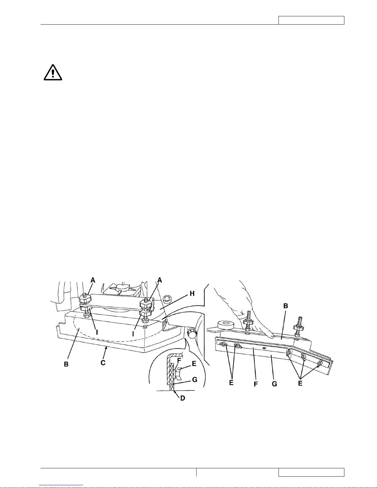
SIDE SKIRT CHECK (AND REPLACEMENT)
Check
Drive the machine on a level oor.
Turn the ignition key (12) to "0".
On both sides of the machine, unscrew the knobs (A) and remove the side skirt assembly (B).
Wash and clean the side skirts.
Check that the side skirt lower edge (C):
lays down on the same level, along all its length;
is integral and free from cuts and lacerations;
has the inner corner (D) that is not worn;
Otherwise overturn or replace the skirts according to the following procedure.
Overturning or replacement
Remove the wing nuts (E), then remove the retaining strip (F).
Remove the skirt blade (G) and, if possible, overturn the blade to replace the lower inner corner (D) with an integral one. If the
other three corners are worn too, replace the blade.
Assembly and height adjustment
Assemble the blades (G) and skirt (B) in the reverse order of disassembly.
Start the machine (according to the procedure shown in the User Manual) and lower the deck (H), then check that the side
skirt blades (G):
slightly touch the oor;
the side blades (G) collect the solution;
otherwise stop the machine and adjust the skirt height with the knobs (A) and (I).
After adjusting, tighten the knobs (A) and (I).
S301325
1.
2.
3.
1.
2.
3.
4.
5.
•
•
•
6.
7.
8.
9.
•
•
Page 22
ENGLISH
SERVICE MANUAL
20
909 6510 000(3)2007-12 Razor Blade 26D / 28D / 28C
BRUSHING SYSTEM
BRUSH/PAD-HOLDER DECK OR CYLINDRICAL BRUSH DECK DISASSEMBLY/ASSEMBLY
NOTE
The machine can be equipped with either the brush/pad-holder deck (69) or the cylindrical brush deck (82), according to
the following procedure.
To assemble/disassemble the deck it is not necessary to remove the brushes/pad-holders.
Disassembly
Drive the machine on a level oor.
Lower the deck (69) or (82) by pressing the switch (4).
Turn the ignition key (12) to "0".
(For brush/pad-holder deck) Disconnect the connector (71). (For cylindrical brush deck) Disconnect the connectors (71) and
(79), then install the protection cover (80) on the connector (79).
Disconnect the solution hose (72).
Remove the two split pins (74) and the split pin for the left lever xing.
Unscrew the knob (73) and remove the brush/pad-holder deck (69), or the cylindrical brush deck (82).
Assembly
Assemble the components in the reverse order of disassembly.
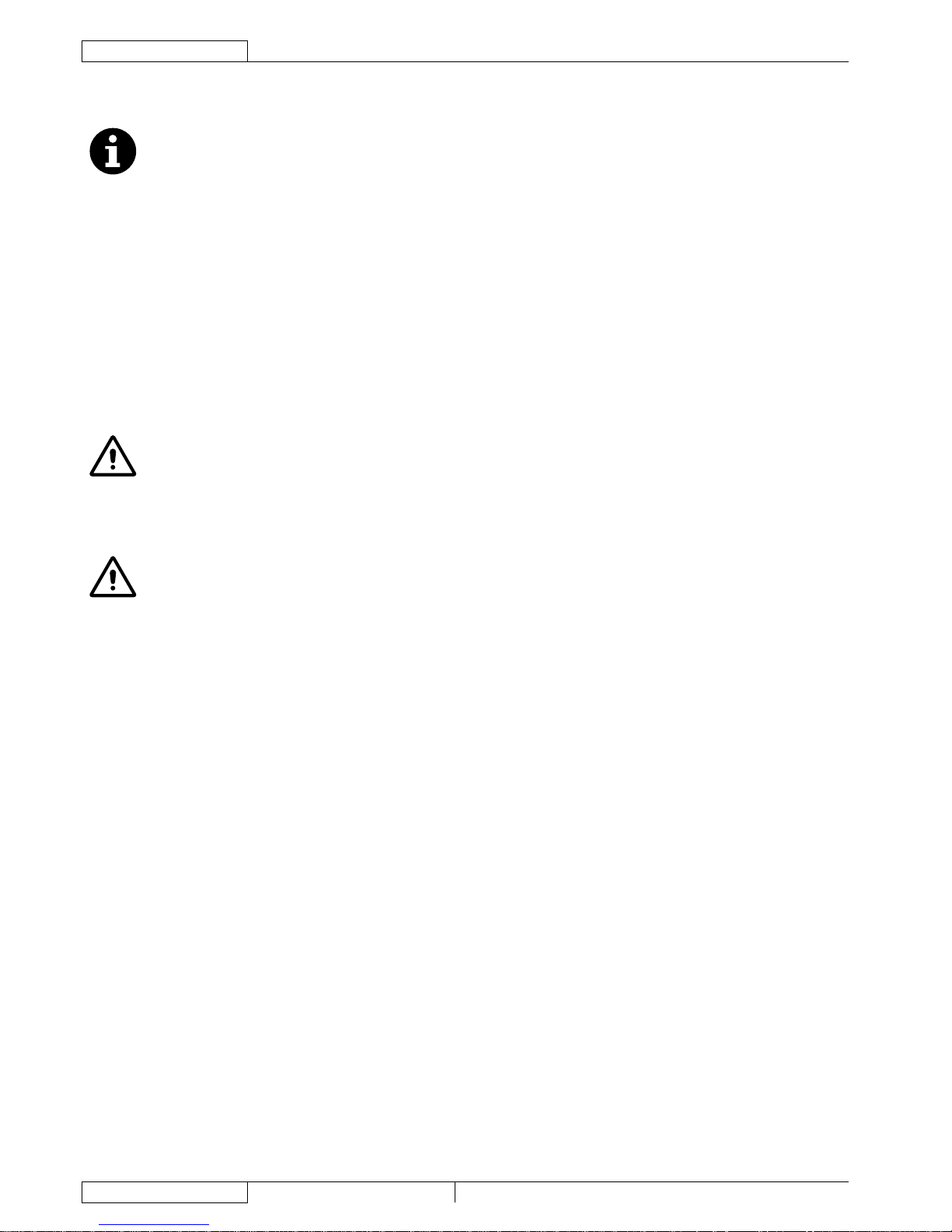
BRUSH MOTOR ELECTRICAL INPUT CHECK
WARNING!
This procedure must be performed by qualied personnel only.
Drive the machine on a level oor.
Remove the brush (76) or (87), or the pad-holder (77) as shown in the User Manual.
Place two wooden shims (A) under the brush/pad-holder deck sides (B), or the cylindrical brush deck (C), as shown in the
gure. The wooden shim height must be 1.5 in (40 mm).
WARNING!
Keep the wooden shims (A) at a proper distance from the brush hubs (D).
Apply the amperometric pliers (E) on one cable (F) of the right motor (G), or on one cable (H) of the left motor (I).
Turn the ignition key (12) to "I".
Press the switch (4) to lower the deck (B) or (C) on the wooden shims (A). When lowering the deck, the brush motors (G) and
(I) start running, then check that the electrical input of the right (G) or left motor (I) is as follows:
3 to 5 A at 24 V, for the brush/pad-holder deck motors;
5 to 6 A, at 24 V, for the cylindrical brush deck motors.
Lift the deck (B) or (C) by pressing the switch (4). Turn the ignition key (12) to "0" and remove the amperometric pliers (E).
If the electrical input is higher, perform the following procedures to detect and correct the abnormal input:
Check if there is dust or dirt (ropes, cables, etc.) on the brush/pad-holder hubs.
Check the motor carbon brushes (see the procedure in the relevant paragraph).
If necessary, disassemble the motor (see the procedure in the relevant paragraph), and check the condition of all its
components.
If the above-mentioned procedures do not lead to a correct electrical input, the motor must be replaced (see the procedure in
the relevant paragraph).
Perform steps 2 and 3 in the reverse order.
1.
2.
3.
4.
5.
6.
7.
8.
1.
2.
3.
4.
5.
6.
•
•
•
•
•
7.
Page 23
SERVICE MANUAL
ENGLISH
Razor Blade 26D / 28D / 28C 909 6510 000(3)2007-12
21
BRUSHING SYSTEM
BRUSH MOTOR ELECTRICAL INPUT CHECK (Continues)
S301326
Page 24
ENGLISH
SERVICE MANUAL
22
909 6510 000(3)2007-12 Razor Blade 26D / 28D / 28C
BRUSHING SYSTEM
DISC BRUSH MOTOR CARBON BRUSH CHECK AND REPLACEMENT
Remove the brush/pad-holder deck (see the procedure in the relevant paragraph).
(For cylindrical brush deck only) Remove the brush motor (see the procedure in the relevant paragraph).
Remove dust and dirt from the motor carbon brush support area (A).
Disengage the fasteners (B) and (C), then remove the four carbon brush supports (A). If necessary, disconnect the electrical
connections (D).
Check the carbon brushes (E) for wear. Replace the carbon brushes when: the contact with the motor armature is insufcient,
the carbon brushes are worn, the carbon brush contact surface is not integral, the thrust spring is broken, etc. The minimum
length of the carbon brushes (E) is 0.59 in (15 mm). When this length is reached, the carbon brushes must replaced.
If necessary, disconnect the connections (F) and remove the carbon brushes with their supports (A) and replace them.
Replace the carbon brushes as an assembly.
Assemble the components in the reverse order of disassembly, and note the following:
When connecting the terminals (F), take care of their insulation from the surrounding parts of the frame.
S301327
CYLINDRICAL BRUSH MOTOR CARBON BRUSH CHECK AND REPLACEMENT
Remove the brush motor (see the procedure in the relevant paragraph).
At the workbench, remove dust and debris from the motor, especially in the area of the protection clamp (A).
Remove the protection clamp (A).
For each carbon brush, move the protection (B) and remove the screws (C).
Remove the carbon brushes (D).
Check if the carbon brushes (D) are worn. Replace the carbon brushes when: the contact with the motor armature is
insufcient, the carbon brushes are worn, the carbon brush contact surface is not integral, the thrust spring is broken, etc.
Replace the carbon brushes as an assembly.
Assemble the components in the reverse order of disassembly.
B
C
B
A
D
S301542A
1.
2.
3.
4.
5.
6.
7.
•
1.
2.
3.
4.
5.
6.
7.
Page 25
SERVICE MANUAL
ENGLISH
Razor Blade 26D / 28D / 28C 909 6510 000(3)2007-12
23
BRUSHING SYSTEM
BRUSH/PAD-HOLDER MOTOR DISASSEMBLY/ASSEMBLY
Disassembly
Remove the brushes/pad-holders, as shown in the User Manual.
Remove the brush/pad-holder deck (see the procedure in the relevant paragraph).
At the workbench, disconnect the motor electrical connections (A).
Cut the motor clamp (B).
Remove the motor screw (C), then remove the relevant hub assembly (D). Recover the key (E).
Remove the four motor screws (F).
Remove the reduction unit (G).
Assembly
Assemble the components in the reverse order of disassembly, and note the following:
Place the reduction units (G) as shown in the gure.
S301328
1.
2.
3.
4.
5.
6.
7.
8.
•
Page 26
ENGLISH
SERVICE MANUAL
24
909 6510 000(3)2007-12 Razor Blade 26D / 28D / 28C
BRUSHING SYSTEM
CYLINDRICAL BRUSH MOTOR DISASSEMBLY/ASSEMBLY
Disassembly
Remove the deck (see the procedure in the relevant paragraph).
Unscrew the knobs (A) and remove the side skirt assembly (B) on the side of the machine where the motor must be removed.
Remove the screw (C), then remove the cover (D).
Loosen the nuts (E) and remove the cover (F).
Loosen the nut (I) and move the pulley (J) to loosen the belt (K).
Remove the belt (K) from the brush motor pulley (L).
Disconnect the brush motor electrical connections (M).
Remove the screws (G), then remove the motor (H).
Assembly
Assemble the components in the reverse order of disassembly, and note the following:
The electrical connections (M) of the motor must be turned upwards;
Install the belt (K) and tension it properly (see the procedure in the relevant paragraph).
S301329
1.
2.
3.
4.
5.
6.
7.
8.
9.
•
•
Page 27

SERVICE MANUAL
ENGLISH
Razor Blade 26D / 28D / 28C 909 6510 000(3)2007-12
25
BRUSHING SYSTEM
CYLINDRICAL BRUSH MOTOR DISASSEMBLY/ASSEMBLY (Continues)
S301330
Page 28

ENGLISH
SERVICE MANUAL
26
909 6510 000(3)2007-12 Razor Blade 26D / 28D / 28C
BRUSHING SYSTEM
CHECK/REPLACEMENT/ADJUSTMENT OF DRIVING BELTS BETWEEN MOTORS AND CYLINDRICAL
BRUSHES
Check
Drive the machine on a level oor.
Turn the ignition key (12) to "0".
On both sides of the machine, unscrew the knobs (A) and remove the side skirt assembly (B).
Remove the screw (C), then remove the covers (D).
Loosen the nuts (E) and remove the covers (F).
Visually inspect the belt (G) for integrity, cuts, tears or cracks and, if necessary, replace it according to the following procedure.
Check the belt tension (G) according to the following procedure.
Replacement
If the belt (G) must be replaced, loosen the nut (J) and move the pulley (K) to loosen the belt.
Tension the belt (G) according to the following procedure.
Belt tensioning
Check the tension of the belt (G) between motor and brush. The tension is correct:
when pressing the belt in its centre with a force of 22 lb (10 kg) (H), the belt bends for 0.35 in (9 mm).
If necessary, tension the belt according to the following procedure:
Loosen the nut (J) and adjust the position of the pulley (K). When tensioning procedure has been performed, tighten the nut
(J).
Repeat step 10.
Reset
Perform steps 3 to 5 in the reverse order.
S301331
1.
2.
3.
4.
5.
6.
7.
8.
9.
10.
•
11.
12.
13.
Page 29

SERVICE MANUAL
ENGLISH
Razor Blade 26D / 28D / 28C 909 6510 000(3)2007-12
27
BRUSHING SYSTEM
CHECK/REPLACEMENT/ADJUSTMENT OF DRIVING BELTS BETWEEN MOTORS AND CYLINDRICAL
BRUSHES (Continues)
S301332
Page 30

ENGLISH
SERVICE MANUAL
28
909 6510 000(3)2007-12 Razor Blade 26D / 28D / 28C
BRUSHING SYSTEM
BRUSH DECK LIFTING/LOWERING ACTUATOR DISASSEMBLY/ASSEMBLY
Disassembly
Drive the machine to the appointed disposal area, and empty the recovery water tank (58) with the hose (22).
Empty the solution tank (59) with the tap (36).
Drive the machine on a level oor.
Turn the ignition key (12) to "0".
Carefully lift the tank assembly (60) to reach the batteries.
Disconnect the battery connector (63).
Remove the deck (see the procedure in the relevant paragraph).
Remove the nuts (A), then carefully remove the cover (B).
Carefully move the electrical component panel (C) and disconnect the deck lifting/lowering actuator connector (D).
Remove the lower mounting screw (E) of the actuator (F).
Remove the screw (G).
Remove the actuator (F).
Assembly
Assemble the components in the reverse order of disassembly.
S301333
1.
2.
3.
4.
5.
6.
7.
8.
9.
10.
11.
12.
13.
Page 31

SERVICE MANUAL
ENGLISH
Razor Blade 26D / 28D / 28C 909 6510 000(3)2007-12
29
BRUSHING SYSTEM
BRUSH DECK LIFTING/LOWERING ACTUATOR DISASSEMBLY/ASSEMBLY (Continues)
S301334
Page 32

ENGLISH
SERVICE MANUAL
30
909 6510 000(3)2007-12 Razor Blade 26D / 28D / 28C
BRUSHING SYSTEM
TROUBLESHOOTING
OPEN CIRCUIT
The fuse (F1) causes an open in the function electronic board supply circuit. This system prevents the circuits from being damaged
in case of failure.
If there is an open in the fuse, the possible causes are:
The function electronic board wiring harness is damaged or shorted (check the power cables on the function electronic board
and the relevant connections).
The function electronic board is damaged (replace).
ALL BRUSHES DO NOT TURN
Possible causes (see also the Electrical System chapter, function electronic board diagnosis):
The function electronic board wiring harness or the brush motors are damaged (repair).
The function electronic board is damaged (replace).
The brush motor is shorted (replace).
ONE BRUSH DO NOT TURN
Possible causes:
The motor carbon brushes are worn (replace).
There are bulky debris or cords around the brushes or between the brushes and their anges (remove the brushes and the
debris).
The motor is faulty (repair or replace).
The wiring harness is damaged (repair).
THE BRUSHES CANNOT BE LIFTED/LOWERED OR THE EXTRA PRESSURE FUNCTION CANNOT BE TURNED
ON
Possible causes (see also the Electrical System chapter, function electronic board diagnosis):
The deck lifting/lowering actuator end-of-strokes are not properly adjusted (adjust).
The deck lifting/lowering actuator end-of-stroke microswitches are broken (replace the actuator).
The deck lifting/lowering actuator is broken (replace).
There is an open in the actuator wiring harness (check the connections according to the procedures shown in the Electrical
System chapter, Troubleshooting paragraph).
THE MACHINE DOES NOT COLLECT THE SOLUTION COMPLETELY
Possible causes:
The side skirts are not properly adjusted (adjust/replace).
1.
2.
1.
2.
3.
1.
2.
3.
4.
1.
2.
3.
4.
1.
Page 33

SERVICE MANUAL
ENGLISH
Razor Blade 26D / 28D / 28C 909 6510 000(3)2007-12
31
RECOVERY WATER SYSTEM
RECOVERY WATER SYSTEM
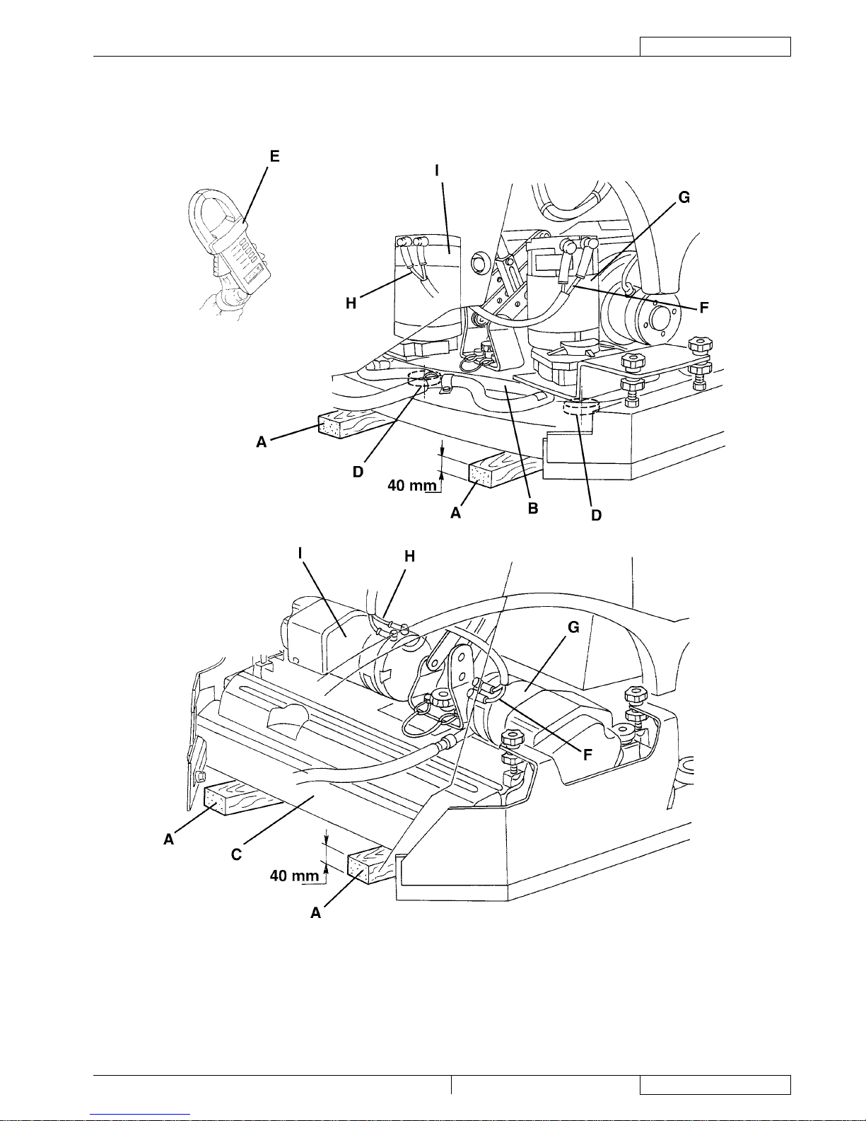
RECOVERY WATER TANK AND VACUUM GRID AUTOMATIC SHUT-OFF FLOAT CLEANING
Drive the machine to the appointed disposal area.
Turn the ignition key (12) to "0".
Lift the cover (45).
Wash with clean water the cover (45), the tank (58) and the vacuum grid (48) with automatic shut-off oat. Drain the water in
the tank through the hose (22).
If necessary, release the fasteners (A) and open the grid (B), recover the oat (C), clean all components and then reinstall
them.
Check the tank cover gasket (D) for integrity.
NOTE
The gasket (D) creates vacuum in the tank that is necessary for vacuuming the recovery water.
If necessary replace the gasket (D) by removing it from its housing (E). When assembling the new gasket, install the joint (F) in
the rear central area, as shown in the gure.
Check the bearing surface (D) of the gasket (G) for integrity and sealing capabilities.
Close the cover (H).
S301335
1.
2.
3.
4.
5.
6.
7.
8.
Page 34

ENGLISH
SERVICE MANUAL
32
909 6510 000(3)2007-12 Razor Blade 26D / 28D / 28C
RECOVERY WATER SYSTEM
VACUUM SYSTEM MOTOR ELECTRICAL INPUT CHECK (before S/N ..........)
WARNING!
This procedure must be performed by qualied personnel only.
Drive the machine to the appointed disposal area, and empty the recovery water tank (58) with the hose (22).
Empty the solution tank (59) with the tap (36).
Drive the machine on a level oor.
Turn the ignition key (12) to "0".
Carefully lift the tank assembly (60).
Apply the amperometric pliers (A) on one cable (B) of the vacuum system motor (C).
Turn the ignition key (12) to "I".
Turn on the vacuum system motor by pressing the switch (6) and check that the motor electrical input is 18 - 22 A at 24 V.
Turn off the vacuum system motor by pressing the switch (6). Turn the ignition key (12) to "0" and remove the amperometric
pliers (A). If the electrical input exceeds the specications, check the motor carbon brushes (see the procedure in the relevant
paragraph). If necessary, disassemble the vacuum system motor (see the procedure in the relevant paragraph), and check the
condition of its moving parts. If the above-mentioned procedures do not lead to a correct electrical input, the motor must be
replaced (see the procedure in the relevant paragraph).
Carefully lower the tank assembly (60).
S301336
1.
2.
3.
4.
5.
6.
7.
8.
9.
Page 35

SERVICE MANUAL
ENGLISH
Razor Blade 26D / 28D / 28C 909 6510 000(3)2007-12
33
RECOVERY WATER SYSTEM
VACUUM SYSTEM MOTOR FILTER CLEANING (starting from S/N ..........)
Disassembly and cleaning
Drive the machine to the appointed disposal area, and empty the recovery water tank (58) with the hose (22).
Empty the solution tank (59) with the tap (36).
Drive the machine on a level oor.
Turn the ignition key (12) to "0".
Disconnect the vacuum hose (23) from the squeegee (24).
Carefully lift the tank assembly (60).
Remove the vacuum system motor lter (D) and clean it with water and compressed air.
Install the lter (D).
Carefully lower the tank assembly (60).
VACUUM SYSTEM MOTOR ELECTRICAL INPUT CHECK (starting from S/N ..........)
WARNING!
This procedure must be performed by qualied personnel only.
Drive the machine to the appointed disposal area, and empty the recovery water tank (58) with the hose (22).
Empty the solution tank (59) with the tap (36).
Drive the machine on a level oor.
Turn the ignition key (12) to "0".
Carefully lift the tank assembly (60).
Apply the amperometric pliers (A) on one cable (B) of the vacuum system motor (C).
Turn the ignition key (12) to "I".
Turn on the vacuum system motor by pressing the switch (6) and check that the motor electrical input is 16 - 19 A at 24 V.
Turn off the vacuum system motor by pressing the switch (6). Turn the ignition key (12) to "0" and remove the amperometric
pliers (A). If the electrical input exceeds the specications, check the motor carbon brushes (see the procedure in the relevant
paragraph). If necessary, disassemble the vacuum system motor (see the procedure in the relevant paragraph), and check the
condition of its moving parts. If the above-mentioned procedures do not lead to a correct electrical input, the motor must be
replaced (see the procedure in the relevant paragraph).
Carefully lower the tank assembly (60).
S301336A
1.
2.
3.
4.
5.
6.
7.
8.
9.
1.
2.
3.
4.
5.
6.
7.
8.
9.
Page 36

ENGLISH
SERVICE MANUAL
34
909 6510 000(3)2007-12 Razor Blade 26D / 28D / 28C
RECOVERY WATER SYSTEM
VACUUM SYSTEM MOTOR CARBON BRUSH CHECK AND REPLACEMENT (before S/N ..........)
Drive the machine to the appointed disposal area, and empty the recovery water tank (58) with the hose (22).
Empty the solution tank (59) with the tap (36).
Drive the machine on a level oor.
Turn the ignition key (12) to "0".
Carefully lift the tank assembly (60) to reach the batteries.
Disconnect the battery connector (63).
Remove the cover (A) from the vacuum system motor (B).
Remove the screws (C).
Disconnect the electrical connections (D).
Remove the carbon brushes (E).
Check the carbon brushes for wear. Replace the carbon brushes when: the contact with the motor armature is insufcient, the
carbon brushes are worn, the carbon brush contact surface is not integral, the thrust spring is broken, etc.
If necessary, replace the carbon brushes. Replace the carbon brushes as an assembly.
Assemble the components in the reverse order of disassembly.
S301337
1.
2.
3.
4.
5.
6.
7.
8.
9.
10.
11.
12.
13.
Page 37

SERVICE MANUAL
ENGLISH
Razor Blade 26D / 28D / 28C 909 6510 000(3)2007-12
35
RECOVERY WATER SYSTEM
VACUUM SYSTEM MOTOR CARBON BRUSH CHECK AND REPLACEMENT (starting from S/N ..........)
Drive the machine to the appointed disposal area, and empty the recovery water tank (58) with the hose (22).
Empty the solution tank (59) with the tap (36).
Drive the machine on a level oor.
Turn the ignition key (12) to "0".
Carefully lift the tank assembly (60) to reach the batteries.
Disconnect the battery connector (63).
Remove the cover (A) from the vacuum system motor (B).
Remove the screws (C).
Disconnect the electrical connections (D).
Remove the carbon brushes (E).
Check the carbon brushes for wear. Replace the carbon brushes when: the contact with the motor armature is insufcient, the
carbon brushes are worn, the carbon brush contact surface is not integral, the thrust spring is broken, etc.
If necessary, replace the carbon brushes. Replace the carbon brushes as an assembly.
Assemble the components in the reverse order of disassembly.
S301337
1.
2.
3.
4.
5.
6.
7.
8.
9.
10.
11.
12.
13.
Page 38

ENGLISH
SERVICE MANUAL
36
909 6510 000(3)2007-12 Razor Blade 26D / 28D / 28C
RECOVERY WATER SYSTEM
VACUUM SYSTEM MOTOR DISASSEMBLY/ASSEMBLY (before S/N ..........)
Disassembly
Drive the machine to the appointed disposal area, and empty the recovery water tank (58) with the hose (22).
Empty the solution tank (59) with the tap (36).
Drive the machine on a level oor.
Turn the ignition key (12) to "0".
Disconnect the vacuum hose (23) from the squeegee (24).
Carefully lift the tank assembly (60).
Disconnect the battery connector (63).
Disconnect the connector (D) from the vacuum system motor.
Remove the screws (A), then remove the recovery water tank (B) with the vacuum hose (C).
Remove the screws (E).
Remove the vacuum system motor (F).
Recover the gasket (G).
Assembly
Assemble the components in the reverse order of disassembly, and note the following:
Check the gasket (G) for integrity and efciency, otherwise replace it.
S301338
1.
2.
3.
4.
5.
6.
7.
8.
9.
10.
11.
12.
13.
•
Page 39

SERVICE MANUAL
ENGLISH
Razor Blade 26D / 28D / 28C 909 6510 000(3)2007-12
37
RECOVERY WATER SYSTEM
VACUUM SYSTEM MOTOR DISASSEMBLY/ASSEMBLY (starting from S/N ..........)
Disassembly
Drive the machine to the appointed disposal area, and empty the recovery water tank (58) with the hose (22).
Empty the solution tank (59) with the tap (36).
Drive the machine on a level oor.
Turn the ignition key (12) to "0".
Disconnect the vacuum hose (23) from the squeegee (24).
Carefully lift the tank assembly (60).
Disconnect the battery connector (63).
Disconnect the connector (D) from the vacuum system motor.
Remove the screws (A), then remove the recovery water tank (B) with the vacuum hose (C).
Remove the screws (E) and recover the washer.
Remove the vacuum motor cover(F).
Recover the Filter (G) and the gasket (H).
Remove the vacuum system motor (I), the acoustic insulation pipe (J) and the acoustic insulation panel (K)
Check the gasket efcency (L) if necessary, replace them.
Assembly
Assemble the components in the reverse order of disassembly, and note the following:
If necessary, clean the lter (G) before assembling it (see the procedure in the relevant paragraph).
S301338A
1.
2.
3.
4.
5.
6.
7.
8.
9.
10.
11.
12.
13.
14.
15.
•
Page 40

ENGLISH
SERVICE MANUAL
38
909 6510 000(3)2007-12 Razor Blade 26D / 28D / 28C
RECOVERY WATER SYSTEM
SQUEEGEE CLEANING/CHECK AND BLADE REPLACEMENT
CAUTION!
It is advisable to wear protective gloves when cleaning the brushes because there may be sharp debris.
Disassembly and cleaning
Drive the machine on a level oor.
Turn the ignition key (12) to "I".
Lower the squeegee (24) by pressing the switch (6).
Turn the ignition key (12) to "0".
Disconnect the vacuum hose (23) from the squeegee.
Loosen the handwheels (27) and remove the squeegee (24).
Wash and clean the squeegee. In particular, clean the compartments (A) and the vacuum hole (B) from dirt and debris. Check
the front blade (C) and rear blade (D) for integrity, cuts and tears; if necessary replace them as shown below.
Assemble the components in the reverse order of disassembly.
Check and replacement
Clean the squeegee as shown in the previous paragraph.
Check that the edges (E) of the front blade and the edges (F) of the rear blade lay down on the same level, along their length;
otherwise adjust their height according to the following procedure:
Disengage the fastener (G) and loosen the wing nuts (H) to adjust the rear blade (D); then tighten the wing nuts and
engage the fastener.
Loosen the wing nuts (I) to adjust the front blade (C); then tighten the wing nuts.
Check the front blade (C) and rear blade (D) for integrity, cuts and tears; if necessary replace them as shown below. Check
that the front corner (J) of the rear blade is not worn; otherwise, overturn the blade to replace the worn corner with an integral
one. If the other corners are worn too, replace the blade according to the following procedure:
Disengage the fastener (G), remove the wing nuts (H) and the retaining strip (K), then replace (or overturn) the rear blade
(D). Install the blade in the reverse order of removal.
Remove the wing nuts (I) and the retaining strip (L), then replace the front blade (C). Install the blade in the reverse order
of removal.
After the blade replacement (or overturning), adjust the height as shown in the previous step.
Assembly
Install the squeegee (24) and screw down the handwheels (27).
Connect the vacuum hose (23) to the squeegee (24).
If necessary, adjust the squeegee balance adjusting handwheel (28).
Lift the squeegee (24) by pressing the switch (6).
S301339
1.
2.
3.
4.
5.
6.
7.
8.
9.
10.
•
•
11.
•
•
11.
12.
13.
14.
15.
Page 41

SERVICE MANUAL
ENGLISH
Razor Blade 26D / 28D / 28C 909 6510 000(3)2007-12
39
RECOVERY WATER SYSTEM
SQUEEGEE LIFTING CABLE SLIDING SHOE LUBRICATION
Lower the squeegee (24), according to the procedure shown in the User Manual.
Remove the batteries and the battery case (see the procedure in the Electrical System chapter).
Clean and lubricate the sliding shoe (A) of the squeegee lifting cable (B) with graphite grease.
Install the batteries and the battery case (see the procedure in the Electrical System chapter).
Lift the squeegee (24).
S301340
1.
2.
3.
4.
5.
Page 42

ENGLISH
SERVICE MANUAL
40
909 6510 000(3)2007-12 Razor Blade 26D / 28D / 28C
RECOVERY WATER SYSTEM
SQUEEGEE LIFTING ACTUATOR DISASSEMBLY/ASSEMBLY
Disassembly
Lift the squeegee (24), according to the procedure shown in the User Manual.
Remove the batteries and the battery case (see the procedure in the Electrical System chapter).
Remove the retaining rings (A) and the pin (B), thus disconnecting the terminal (C) of the squeegee lifting cable (D).
Remove the screw (E).
Disconnect the connector (F) of the actuator (I).
Disconnect the actuator connector (G) from the clamps (H).
Remove the squeegee lifting actuator (I).
Assembly
Assemble the components in the reverse order of disassembly.
S301341
1.
2.
3.
4.
5.
6.
7.
8.
Page 43

SERVICE MANUAL
ENGLISH
Razor Blade 26D / 28D / 28C 909 6510 000(3)2007-12
41
RECOVERY WATER SYSTEM
SQUEEGEE LIFTING CABLE DISASSEMBLY/ASSEMBLY
Disassembly
Lift the squeegee (24), according to the procedure shown in the User Manual.
Remove the batteries and the battery case (see the procedure in the Electrical System chapter).
Remove the retaining rings (A) and the pin (B), thus disconnecting the terminal (C) of the squeegee lifting cable (D).
Remove the screw (E) and recover the washer (F).
Remove the guide (G).
Carefully lower the tank assembly (59).
Remove the nut and the locknut (H), then remove the lifting cable (I) from the squeegee assembly (J).
Assembly
Assemble the components in the reverse order of disassembly, and note the following:
Before assembling the lifting cable (I), lubricate the squeegee lifting cable sliding shoe (K) with graphite grease.
After installing the squeegee lifting cable, adjust the nut and the locknut (I) so that, when the squeegee is completely lifted,
the distance from the oor is 0.78 in (20 mm).
S301342
1.
2.
3.
4.
5.
6.
7.
8.
•
•
Page 44

ENGLISH
SERVICE MANUAL
42
909 6510 000(3)2007-12 Razor Blade 26D / 28D / 28C
RECOVERY WATER SYSTEM
TROUBLESHOOTING
THE VACUUM SYSTEM MOTOR DOES NOT TURN ON
The function electronic board supplies current to the vacuum system motor directly; if the motor does not work, possible causes are
the following (see also the Electrical System chapter, function electronic board diagnosis):
The vacuum system motor carbon brushes are worn (replace).
The vacuum system motor is faulty (check the electrical input).
The function electronic board is damaged (replace).
DIRTY WATER VACUUMING IS INSUFFICIENT OR THERE IS NO VACUUMING
Possible causes:
The vacuum grid with automatic shut-off oat is activated because the recovery water tank is full (empty the recovery water
tank).
The grid is dirty (clean).
The tank cover is not correctly positioned (adjust).
The tank cover gasket is not efcient (replace).
The squeegee or the vacuum hose is clogged or damaged (clean or repair/replace).
The vacuum gaskets are damaged or do not match perfectly (repair or replace).
THE SQUEEGEE LEAVES LINING ON THE FLOOR OR DOES NOT COLLECT WATER
Possible causes:
There is debris under the blade (remove).
The squeegee blade edges are torn or worn (replace).
The squeegee is not balanced (adjust it with the relevant handwheel).
The recovery water drain hose plug is open (close).
THE SQUEEGEE DOES NOT LIFT/LOWER
Possible causes (see also the Electrical System chapter, function electronic board diagnosis):
The actuator is faulty (repair/replace).
1.
2.
3.
1.
2.
3.
4.
5.
6.
1.
2.
3.
4.
1.
Page 45

SERVICE MANUAL
ENGLISH
Razor Blade 26D / 28D / 28C 909 6510 000(3)2007-12
43
PARKING BRAKE SYSTEM
PARKING BRAKE SYSTEM
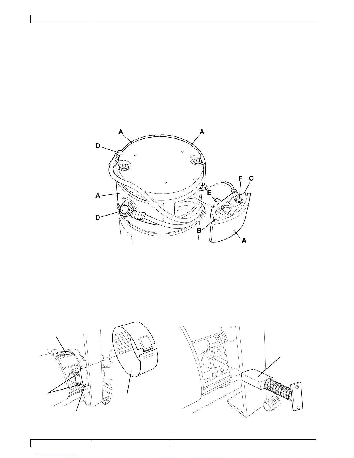
PARKING BRAKE CHECK
Lift the brushes and the squeegee, then drive the machine on a dry oor that offers a good grip.
Turn the ignition key (12) to "0".
Get off of the machine and push it manually in the direction shown by the arrow (A), then check that the front wheel (B) is
locked.
If necessary, replace the electromagnetic brake (see the procedure in the relevant paragraph).
B (*)
A
B (**)
S301640
(*) Machines up to January 2007
(**) Machines after January 2007
1.
2.
3.
Page 46

ENGLISH
SERVICE MANUAL
44
909 6510 000(3)2007-12 Razor Blade 26D / 28D / 28C
PARKING BRAKE SYSTEM
ELECTROMAGNETIC BRAKE DISASSEMBLY/ASSEMBLY (Machines up to January 2007)
Disassembly
Drive the machine to the appointed disposal area, and empty the recovery water tank (58) with the hose (22).
Empty the solution tank (59) with the tap (36).
Place the machine on a hoisting system (if available). Otherwise, drive the machine on a level oor.
Turn the ignition key (12) to "0".
Carefully lift the tank assembly (60).
Disconnect the battery connector (63).
Apply proper wedges to right and left rear wheels (43), so that the machine cannot move when the electromagnetic brake (39)
is disassembled.
Disconnect the electromagnetic brake connector (A).
Disconnect the wiring harness (B) from the clamps (C).
Remove the self-locking nut (D) and the unlocking handwheel (E).
Remove the screws (F), then remove the cover (G).
Remove the electromagnetic brake mounting screws (H).
Remove the electromagnetic brake (I).
Remove the brake pad (J).
Assembly
Assemble the components in the reverse order of disassembly, and note the following:
Before assembling the cover (G), check the gasket (L) for dirt, integrity and correct positioning.
To activate the electromagnetic brake, the self-locking nut (D) must be ush with the threaded tie rod (K), while the
unlocking handwheel (E) must be unscrewed until it contacts the nut (D) (as shown in the gure).
WARNING!
When the unlocking handwheel (E) is unscrewed, the electromagnetic brake is activated; when the unlocking
handwheel (E) is screwed, the electromagnetic brake is deactivated.
Check the parking brake (see the procedure in the relevant paragraph).
1.
2.
3.
4.
5.
6.
7.
8.
9.
10.
11.
12.
13.
14.
15.
•
•
16.
Page 47

SERVICE MANUAL
ENGLISH
Razor Blade 26D / 28D / 28C 909 6510 000(3)2007-12
45
PARKING BRAKE SYSTEM
ELECTROMAGNETIC BRAKE DISASSEMBLY/ASSEMBLY (Machines up to January 2007)
(Continues)
S301344
Page 48

ENGLISH
SERVICE MANUAL
46
909 6510 000(3)2007-12 Razor Blade 26D / 28D / 28C
PARKING BRAKE SYSTEM
ELECTROMAGNETIC BRAKE AND DISC WITH BRAKING MASSES DISASSEMBLY/ASSEMBLY
(Machines after January 2007)
Disassembly
Drive the machine to the appointed disposal area, and empty the recovery water tank (58) with the hose (22).
Empty the solution tank (59) with the tap (36).
Place the machine on a hoisting system (if available).
Otherwise, drive the machine on a level oor.
Turn the ignition key (12) to "0".
Carefully lift the tank assembly (60).
Disconnect the battery connector (63).
Apply proper wedges to right and left rear wheels (43), so that the machine cannot move when the electromagnetic brake (39)
is disassembled.
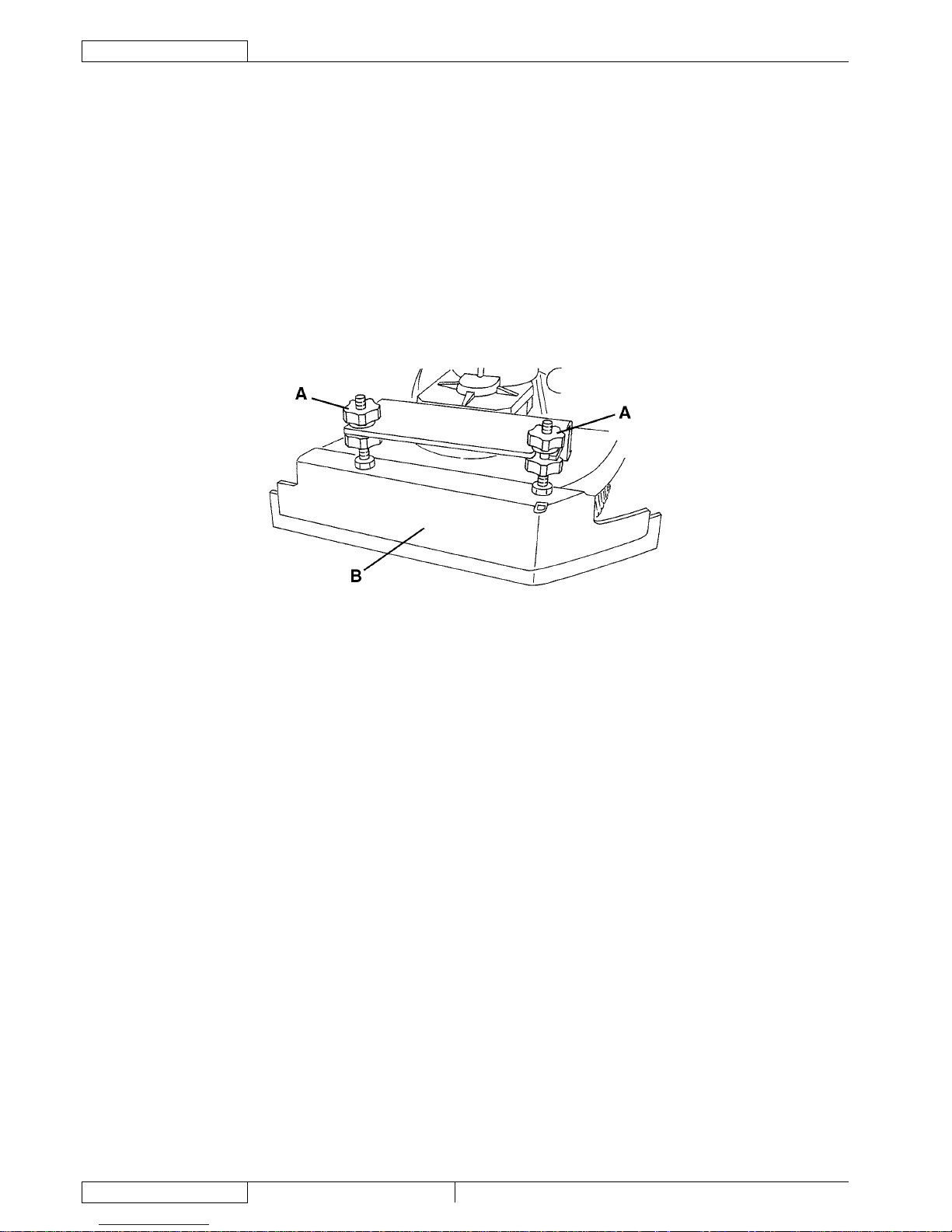
Cut the fastening clamps (A).
Disconnect the electromagnetic brake connector (B).
Remove the screws (C), then remove the case (D) by disengaging the wiring harness grommet (E).
Remove the screws (F), then remove the electromagnetic brake (G).
Remove the disc with braking masses (H). Check the thickness (J) of the braking masses (K) and, if it is lower than 0.039 in (1
mm), the disc (H) must be replaced.
If necessary, remove the ange (I).
Assembly
Assemble the components in the reverse order of disassembly, and note the following:
Before assembling the electromagnetic brake (G), clean it with compressed air; then install the threaded dowels (N) so that
they are ush with the surface (O).
After assembling the electromagnetic brake (G), check that the air gap (L) is 0.007 to 0.012 in (0.19 to 0.31 mm); if
necessary adjust the air gap (L) by using the adjusting spacers (M).
Check the parking brake (see the procedure in the relevant paragraph).
A
B
A
E
C
D
C
S301641
1.
2.
3.
4.
5.
6.
7.
8.
9.
10.
11.
12.
13.
14.
•
•
15.
Page 49

SERVICE MANUAL
ENGLISH
Razor Blade 26D / 28D / 28C 909 6510 000(3)2007-12
47
PARKING BRAKE SYSTEM
ELECTROMAGNETIC BRAKE AND DISC WITH BRAKING MASSES DISASSEMBLY/ASSEMBLY
(Machines after January 2007) (Continues)
N
N
M
O
L
F
F
F
G
H
I
H
K
J
J
S301642
Page 50

ENGLISH
SERVICE MANUAL
48
909 6510 000(3)2007-12 Razor Blade 26D / 28D / 28C
PARKING BRAKE SYSTEM
TROUBLESHOOTING
THE BRAKE DOES NOT OPERATE
Possible causes:
The electromagnetic brake unlocking handwheel (41) is screwed (unscrew and remove).
The braking masses are not efcient (replace the electromagnetic brake).
(Machines after January 2007) The electromagnetic brake air gap is not properly adjusted (adjust).
THE BRAKE DOES NOT DEACTIVATE WHEN PRESSING THE FORWARD/REVERSE GEAR PEDAL
Possible causes:
There is an open in the wiring harness between the drive system electronic board and the electromagnetic brake (check/repair
the wiring harness/electrical connections).
The electromagnetic brake is faulty (replace).
The drive system electronic board is faulty (replace).
1.
2.
3.
1.
2.
3.
Page 51

SERVICE MANUAL
ENGLISH
Razor Blade 26D / 28D / 28C 909 6510 000(3)2007-12
49
DRIVE SYSTEM
DRIVE SYSTEM
DRIVING WHEEL COVER DISASSEMBLY/ASSEMBLY (Machines up to January 2007)
Disassembly
Drive the machine to the appointed disposal area, and empty the recovery water tank (58) with the hose (22).
Empty the solution tank (59) with the tap (36).
Place the machine on a hoisting system (if available). Otherwise, drive the machine on a level oor.
Turn the ignition key (12) to "0".
Remove the brush/pad-holder deck (16) or the cylindrical brush deck (17) (see the procedure in the relevant paragraph).
Turn the front wheel (A) completely to the left.
Apply proper wedges to right and left rear wheels (43), so that the machine cannot move when the front wheel (A) is lifted.
With the help of an assistant, slightly lift the front part of the machine and apply to the frame brackets (B) two proper wooden
shims (C) high enough to keep the front wheel (A) lifted for about 1.18 in (3 cm) from the oor.
Lift the tank assembly (60) and disconnect the battery connector (63).
Disconnect the electrical connections (D) from the drive system motor.
Remove the screws (E), then remove the driving wheel cover (F).
Assembly
Assemble the components in the reverse order of disassembly.
S301345
1.
2.
3.
4.
5.
6.
7.
8.
9.
10.
11.
12.
Page 52

ENGLISH
SERVICE MANUAL
50
909 6510 000(3)2007-12 Razor Blade 26D / 28D / 28C
DRIVE SYSTEM
DRIVING WHEEL COVER DISASSEMBLY/ASSEMBLY (Machines after January 2007)
Disassembly
Drive the machine to the appointed disposal area, and empty the recovery water tank (58) with the hose (22).
Empty the solution tank (59) with the tap (36).
Place the machine on a hoisting system (if available).
Otherwise, drive the machine on a level oor.
Turn the ignition key (12) to "0".
Remove the brush/pad-holder deck (16) or the cylindrical brush deck (17) (see the procedure in the relevant paragraph).
Turn the front wheel (R) completely to the left.
Apply proper wedges to right and left rear wheels (43), so that the machine cannot move when the front wheel (R) is lifted.
With the help of an assistant, slightly lift the front part of the machine and apply to the frame brackets (S) two proper wooden
shims (T) high enough to keep the front wheel (R) lifted for about 1.18 in (3 cm) from the oor.
Lift the tank assembly (60) and disconnect the battery connector (63).
Remove the wiring harness fastening clamp (A).
Cut the fastening clamps (B) of the connector (C).
Disconnect the electromagnetic brake connector (C).
Remove the screws (D), then remove the cover (E).
Disconnect the electrical connections (F).
Remove the screws (G), then remove the driving wheel assembly (H).
At the workbench, remove the electromagnetic brake (see the procedure in the relevant paragraph).
Remove the screws (I), then remove the plate (J).
With a puller (K) remove the brush side bracket (L).
Remove the mounting screws (M) of the driving wheel cover (N). Recover the nuts (P) and washers (O).
Remove the cover (N) from the reduction unit (Q).
Assembly
Assemble the components in the reverse order of disassembly, and note the following:
If necessary, use a rubber mallet to install the cover (N).
Tighten the screws (M) at 141.61 lbf·in (16 N·m; 1.63 kgf·m).
Tighten the screws (I) at 194.71 lbf·in (22 N·m; 2.24 kgf·m).
F
D
E
C
A
B
B
S301643
1.
2.
3.
4.
5.
6.
7.
8.
9.
10.
11.
12.
13.
14.
15.
16.
17.
18.
19.
20.
21.
•
•
•
Page 53

SERVICE MANUAL
ENGLISH
Razor Blade 26D / 28D / 28C 909 6510 000(3)2007-12
51
DRIVE SYSTEM
DRIVING WHEEL COVER DISASSEMBLY/ASSEMBLY (Machines after January 2007) (Continues)
S T R T
I
I
J
P O
P
O
Q
N
O
O
M
M
L
L
K
G
G
H
S
S301644
Page 54

ENGLISH
SERVICE MANUAL
52
909 6510 000(3)2007-12 Razor Blade 26D / 28D / 28C
DRIVE SYSTEM
DRIVE SYSTEM MOTOR ELECTRICAL INPUT CHECK (Machines up to January 2007)
WARNING!
This procedure must be performed by qualied personnel only.
Drive the machine on a level oor.
Turn the ignition key (12) to "0".
Remove the brush/pad-holder deck (16) or the cylindrical brush deck (17) (see the procedure in the relevant paragraph).
Turn the front wheel (A) completely to the left.
Apply proper wedges to right and left rear wheels (43), so that the machine cannot move when the front wheel (A) is lifted.
With the help of an assistant, slightly lift the front part of the machine and apply to the frame brackets (B) two proper wooden
shims (C) high enough to keep the front wheel (A) lifted for about 1.18 in (3 cm) from the oor.
WARNING!
When performing the following procedure, pay attention to the rotation of the driving wheel (A).
Apply the amperometric pliers (D) on the positive cables (red) (E). The amperometric pliers must not touch the wheel.
Seat on the machine driver's seat (37).
Turn the ignition key (12) to "I".
Drive the machine at the maximum forward speed by pressing the pedal (15) and check that the electrical input is 10 - 15 A at
24 V. Release the pedal (15). Turn the ignition key (12) to "0" and remove the amperometric pliers (D). If the electrical input is
higher, perform the following procedures to detect and correct the abnormal input:
Check if there is dust or debris preventing the wheel rotation.
Check if the electromagnetic brake slows down the wheel when the drive system motor is operating (remove the
electromagnetic brake and repeat the electrical input check (see the procedure in the relevant paragraph)).
Check the motor carbon brushes (see the procedure in the relevant paragraph).
If necessary, disassemble the motor (see the procedure in the relevant paragraph), and check the condition of all its
components.
If the above-mentioned procedures do not lead to a correct electrical input, the motor must be replaced (see the procedure in
the relevant paragraph).
Perform steps 3 to 6 in the reverse order.
S301346
1.
2.
3.
4.
5.
6.
7.
8.
9.
10.
•
•
•
•
11.
Page 55

SERVICE MANUAL
ENGLISH
Razor Blade 26D / 28D / 28C 909 6510 000(3)2007-12
53
DRIVE SYSTEM
DRIVE SYSTEM MOTOR ELECTRICAL INPUT CHECK (Machines after January 2007)
WARNING!
This procedure must be performed by qualied personnel only.
Drive the machine on a level oor.
Turn the ignition key (12) to "0".
Remove the brush/pad-holder deck (16) or the cylindrical brush deck (17) (see the procedure in the relevant paragraph).
Turn the front wheel (A) completely to the left.
Apply proper wedges to right and left rear wheels (43), so that the machine cannot move when the front wheel (A) is lifted.
With the help of an assistant, slightly lift the front part of the machine and apply to the frame brackets (B) two proper wooden
shims (C) high enough to keep the front wheel (A) lifted for about 1.18 in (3 cm) from the oor.
WARNING!
When performing the following procedure, pay attention to the rotation of the driving wheel (A).
Apply the amperometric pliers (D) on the positive cables (red) (E). The amperometric pliers must not touch the wheel.
Seat on the machine driver's seat (37).
Turn the ignition key (12) to "I".
Drive the machine at the maximum forward speed by pressing the pedal (15) and check that the electrical input is 10 - 15 A at
24 V. Release the pedal (15). Turn the ignition key (12) to "0" and remove the amperometric pliers (D).
If the electrical input is higher, perform the following procedures to detect and correct the abnormal input:
Check if there is dust or debris preventing the wheel rotation.
Check if the electromagnetic brake slows down the wheel when the drive system motor is operating (remove the
electromagnetic brake and repeat the electrical input check (see the procedure in the relevant paragraph)).
Check the motor carbon brushes (see the procedure in the relevant paragraph).
If necessary, disassemble the motor (see the procedure in the relevant paragraph), and check the condition of all its
components.
If the above-mentioned procedures do not lead to a correct electrical input, the motor must be replaced (see the procedure in
the relevant paragraph).
Perform steps 3 to 6 in the reverse order.
D
B
C
A
E
C
B
S301645
1.
2.
3.
4.
5.
6.
7.
8.
9.
10.
•
•
•
•
11.
Page 56

ENGLISH
SERVICE MANUAL
54
909 6510 000(3)2007-12 Razor Blade 26D / 28D / 28C
DRIVE SYSTEM
DRIVE SYSTEM MOTOR CARBON BRUSH CHECK AND REPLACEMENT (Machines up to January
2007)
Check
Drive the machine to the appointed disposal area, and empty the recovery water tank (58) with the hose (22).
Empty the solution tank (59) with the tap (36).
Place the machine on a hoisting system (if available). Otherwise, drive the machine on a level oor.
Turn the ignition key (12) to "0".
Carefully lift the tank assembly (60).
Disconnect the battery connector (63).
Remove dust and debris from the drive system motor outer part (F), then disengage and remove the clamp (A) from the motor.
Lift the retaining springs (B) and remove the four carbon brushes (C).
Check the carbon brushes for wear. Replace the carbon brushes when: the contact with the motor armature is insufcient, the
carbon brushes are worn, the carbon brush contact surface is not integral, the thrust spring is broken, etc.
Replacement
If necessary, remove the nuts (D) and disengage the lead-in wires (E), then remove the carbon brushes.
Reset
Assemble the components in the reverse order of disassembly.
S301347
1.
2.
3.
4.
5.
6.
7.
8.
9.
10.
11.
Page 57

SERVICE MANUAL
ENGLISH
Razor Blade 26D / 28D / 28C 909 6510 000(3)2007-12
55
DRIVE SYSTEM
DRIVE SYSTEM MOTOR CARBON BRUSH CHECK AND REPLACEMENT (Machines after January
2007)
Check and replacement
Drive the machine to the appointed disposal area, and empty the recovery water tank (58) with the hose (22).
Empty the solution tank (59) with the tap (36).
Place the machine on a hoisting system (if available).
Otherwise, drive the machine on a level oor.
Turn the ignition key (12) to "0".
Carefully lift the tank assembly (60).
Disconnect the battery connector (63).
Remove the drive system motor carbon brush covers (A) (bayonet joint).
Remove the gasket (B) and check them for integrity and efciency; if necessary, replace them.
Remove the screws (C), then remove the four carbon brushes (D).
Check the carbon brushes (D) for wear. Replace the carbon brushes when: the contact with the motor armature is insufcient,
the carbon brushes are worn, the carbon brush contact surface is not integral, the thrust spring is broken, etc.
If necessary, replace the carbon brushes.
Reset
Assemble the components in the reverse order of disassembly.
A
A
A
A
C
D
B
D
S301646
1.
2.
3.
4.
5.
6.
7.
8.
9.
10.
11.
Page 58

ENGLISH
SERVICE MANUAL
56
909 6510 000(3)2007-12 Razor Blade 26D / 28D / 28C
DRIVE SYSTEM
DRIVE SYSTEM MOTOR SLIDING CONTACT CHECK AND REPLACEMENT (Machines after January
2007)
Check and replacement
Drive the machine to the appointed disposal area, and empty the recovery water tank (58) with the hose (22).
Empty the solution tank (59) with the tap (36).
Place the machine on a hoisting system (if available).
Otherwise, drive the machine on a level oor.
Turn the ignition key (12) to "0".
Carefully lift the tank assembly (60).
Disconnect the battery connector (63).
Remove the screws (A), then remove the sliding contact cover (B).
Disconnect the sliding contact connections (C).
Remove the sliding contact mounting screws (D) and nuts (E). Recover the washer (E).
Remove both sliding contacts (G).
Check the sliding contacts (D) for wear. Replace the sliding contacts when: the contact with the sliding ring is insufcient, the
sliding contacts are worn, the contact surface is not integral, the thrust spring is broken, etc.
If necessary, replace the sliding contacts.
Reset
Assemble the components in the reverse order of disassembly, and note the following:
The sliding contact surface (H) must be turned downwards, as shown in the gure.
C
C
A
A
B
S301647
1.
2.
3.
4.
5.
6.
7.
8.
9.
10.
11.
12.
•
Page 59

SERVICE MANUAL
ENGLISH
Razor Blade 26D / 28D / 28C 909 6510 000(3)2007-12
57
DRIVE SYSTEM
DRIVE SYSTEM MOTOR SLIDING CONTACT CHECK AND REPLACEMENT (Machines after January
2007) (Continues)
D
G
F
E
D
E
G
D
G
E
H
H
S301648
Page 60

ENGLISH
SERVICE MANUAL
58
909 6510 000(3)2007-12 Razor Blade 26D / 28D / 28C
DRIVE SYSTEM
DRIVE SYSTEM MOTOR DISASSEMBLY/ASSEMBLY (Machines up to January 2007)
Disassembly
Remove the electromagnetic brake (see the procedure in the relevant paragraph).
Remove the connectors (A) from the drive system motor (B).
Remove the retaining ring (C) on the electromagnetic brake side.
Remove the ring gear (D) and recover the key (E).
Mark the position (G) of the ange (H) on the wheel support (I), for proper reassembly.
Remove the screws (F), then remove the ange (H).
Remove the screws (J).
If necessary, to remove the drive system motor (K), hit the shaft (L) with a plastic mallet.
Assembly
Assemble the components in the reverse order of disassembly, and note the following:
The connectors (A) of the drive system motor (K) must be turned upwards.
If the bearing (M) comes out of its seat, reinsert it by pushing it on the outer ring by using a bush with appropriate diameter.
S301348
1.
2.
3.
4.
5.
6.
7.
8.
9.
•
•
Page 61

SERVICE MANUAL
ENGLISH
Razor Blade 26D / 28D / 28C 909 6510 000(3)2007-12
59
DRIVE SYSTEM
DRIVE SYSTEM MOTOR, BEARING AND GASKET DISASSEMBLY/ASSEMBLY (Machines after
January 2007)
Disassembly
Drive the machine to the appointed disposal area, and empty the recovery water tank (58) with the hose (22).
Empty the solution tank (59) with the tap (36).
Place the machine on a hoisting system (if available).
Otherwise, drive the machine on a level oor.
Turn the ignition key (12) to "0".
Remove the brush/pad-holder deck (16) or the cylindrical brush deck (17) (see the procedure in the relevant paragraph).
Turn the front wheel (AG) completely to the left.
Apply proper wedges to right and left rear wheels (43), so that the machine cannot move when the front wheel (AG) is lifted.
With the help of an assistant, slightly lift the front part of the machine and apply to the frame brackets (AH) two proper wooden
shims (AI) high enough to keep the front wheel (AG) lifted for about 1.18 in (3 cm) from the oor.
Lift the tank assembly (60) and disconnect the battery connector (63).
Remove the wiring harness fastening clamp (A).
Cut the fastening clamps (B) of the connector (C).
Disconnect the electromagnetic brake connector (C).
Remove the screws (D), then remove the cover (E).
Disconnect the electrical connections (F).
F
D
E
C
A
B
B
S301643
1.
2.
3.
4.
5.
6.
7.
8.
9.
10.
11.
12.
13.
14.
Page 62

ENGLISH
SERVICE MANUAL
60
909 6510 000(3)2007-12 Razor Blade 26D / 28D / 28C
DRIVE SYSTEM
DRIVE SYSTEM MOTOR, BEARING AND GASKET DISASSEMBLY/ASSEMBLY (Machines after
January 2007) (Continues)
Remove the screws (G), then remove the driving wheel assembly (H).
At the workbench, remove the electromagnetic brake (see the procedure in the relevant paragraph).
Remove the screws (I), then remove the plate (J).
With a puller (K) remove the brush side bracket (L).
Remove the mounting screws (M) of the driving wheel cover (N). Recover the nuts (P) and washers (O).
Remove the cover (N) from the reduction unit (Q).
If necessary, remove the screws (S) and the fasteners (T), then remove the bearing (R); if necessary, use a puller.
Remove the four screws (U), then remove the carbon brushes holder assembly (V).
If necessary, remove the bearing (W).
With a puller (K) remove the brush side bracket (X).
If necessary, remove the screws (Z) and the fasteners (AA), then remove the bearing (Y); if necessary, use a puller.
Remove the motor (AB) from the reduction unit (AC). Do not let the oil coming out of the hole (AF). Do not let dust and dirt
enter the reduction unit through the hole (AF).
If necessary, remove the bearing (AD).
If necessary, remove the oil seal (AE).
Assembly
Assemble the components in the reverse order of disassembly, and note the following:
the reduction unit spare part (AC) is already lled with oil (AGIP BLASIA 150; quantity 21 cl).
If necessary, use a rubber mallet to install the cover (N).
Tighten the screws (M) at 141.61 lbf·in (16 N·m; 1.63 kgf·m).
Tighten the screws (I) at 194.71 lbf·in (22 N·m; 2.24 kgf·m).
AH AI AG AI
H
AH
G
G
S301649
15.
16,
17.
18.
19.
20.
21.
22.
23.
24.
25.
26.
27.
28.
29.
•
•
•
•
Page 63

SERVICE MANUAL
ENGLISH
Razor Blade 26D / 28D / 28C 909 6510 000(3)2007-12
61
DRIVE SYSTEM
DRIVE SYSTEM MOTOR, BEARING AND GASKET DISASSEMBLY/ASSEMBLY (Machines after
January 2007) (Continues)
J
P O
P
O
Q
N
O
O
M
M
L
K
I
I
L
AF
X
Y
Z
AA
AC
AB
AE
AD
W
V
U
U R
T
S
S301650
Page 64

ENGLISH
SERVICE MANUAL
62
909 6510 000(3)2007-12 Razor Blade 26D / 28D / 28C
DRIVE SYSTEM
FORWARD/REVERSE GEAR PEDAL DISASSEMBLY/ASSEMBLY
Disassembly
Drive the machine on a level oor.
Engage the parking brake.
Remove the pedal mounting screws (A).
Slightly lift the pedal (B) and disconnect the connector (C).
Assembly
Assemble the components in the reverse order of disassembly.
S301349
1.
2.
3.
4.
5.
Page 65

SERVICE MANUAL
ENGLISH
Razor Blade 26D / 28D / 28C 909 6510 000(3)2007-12
63
DRIVE SYSTEM
FORWARD/REVERSE GEAR PEDAL POTENTIOMETER CHECK AND ADJUSTMENT
Remove the forward/reverse gear pedal (see the procedure in the relevant paragraph).
At the workbench, remove the screws (A), then remove the protection (B).
Apply a tester on the connector centre contact (C) and on the side contact (D), then check that the resistance is 2,500 ± 500 Ω
(Ohm) when the pedal is released. If necessary, reset the resistance correct value by loosening the screw (F) and operating on
the potentiometer screw (E). Then tighten the screw (F).
Install the protection (B) and tighten the screws (A).
Install the forward/reverse gear pedal (see the procedure in the relevant paragraph).
S301350
1.
2.
3.
4.
5.
Page 66

ENGLISH
SERVICE MANUAL
64
909 6510 000(3)2007-12 Razor Blade 26D / 28D / 28C
DRIVE SYSTEM
SPEED REDUCTION SENSOR CHECK/ADJUSTMENT
Check
According to the procedure shown in the User Manual, lift the brush/pad-holder deck and the squeegee, then start the
machine, drive it at high speed, make turns both on the right and on the left, and check the following:
When the steering wheel (14) is turned for more than 1/4 turn (approximately), both on the right and on the left, the
machine speed automatically decreases consistently.
The machine is equipped with an anti-tilting safety system that reduces the speed when turning, irrespectively of the pressure
on the pedal.
The reduction of speed when turning is not a malfunction but a characteristic that improves the machine stability in every
condition.
If necessary, adjust the speed reduction sensor according to the following procedure.
Adjustment
Place the machine on a hoisting system (if available). Otherwise, drive the machine on a level oor.
Turn the ignition key (12) to "0".
Clean the ange (A) in the area where the speed reduction sensor (B) operates.
Turn the steering wheel until the sensor (B) moves out of the deactivation area (C).
Temporarily turn the ignition key (12) to “I” with care, and check the area (D) to see if the sensor is active.
Turn the ignition key (12) to "0".
Turn the steering wheel to the right and to the left and check that the maximum distance between the sensor (B) and the ange
(A) is 0.059 in (1.5 mm). Check that the sensor (B) never comes into contact with the ange (A).
If necessary, loosen the nuts (E) and adjust the position of the sensor (B). After adjusting, tighten the nuts (E).
Remove the machine from the hoisting system and check again (steps 1 and 2).
S301351
1.
•
2.
3.
4.
5.
6.
7.
8.
9.
10.
11.
Page 67

SERVICE MANUAL
ENGLISH
Razor Blade 26D / 28D / 28C 909 6510 000(3)2007-12
65
DRIVE SYSTEM
SPEED REDUCTION SENSOR REPLACEMENT
Disassembly
Remove the front fairing (see the procedure in the relevant paragraph).
Remove the nuts (93), then remove the cover (92).
Slightly move the electrical component panel (100).
Disconnect the speed reduction sensor connector (A).
Remove two mounting screws (H) of the foot board (I).
Lift the foot board (J) and remove the sensor cable (K) through the passage (L).
Remove the nuts (M), then remove the speed reduction sensor (N) with the cable.
Assembly
Assemble the components in the reverse order of disassembly, and note the following:
Insert the speed reduction sensor wiring harness (O) with the connector (P) disconnected; then connect the wiring harness
to the connector (P), paying attention to the cable colours.
Adjust the speed reduction sensor (see the procedure in the relevant paragraph).
S301398
1.
2.
3.
4.
5.
6.
7.
8.
•
•
Page 68

ENGLISH
SERVICE MANUAL
66
909 6510 000(3)2007-12 Razor Blade 26D / 28D / 28C
DRIVE SYSTEM
SPEED REDUCTION SENSOR REPLACEMENT (Continues)
S301353
Page 69

SERVICE MANUAL
ENGLISH
Razor Blade 26D / 28D / 28C 909 6510 000(3)2007-12
67
DRIVE SYSTEM
DRIVER'S SEAT SAFETY MICROSWITCH OPERATION CHECK
Check for proper machine operation in forward and reverse gear, as shown in the User Manual.
Check that the ignition key (12) is turned to “I” and that the battery green warning light (7a) is on.
Slightly lift from the seat (37) and try to start the machine with the hands on the steering wheel and by gradually pressing the
pedal (15), both in forward and in reverse gear: Check that the machine can move neither forward nor backward. Otherwise,
check the proper operation of the safety system that prevents the machine movement if the operator is not seating on the
driver's seat, according to the following procedure:
Check for driver's seat microswitch proper operation, otherwise replace it according to the following procedure.
If necessary, check the driver's seat microswitch wiring harness.
DRIVER'S SEAT SAFETY MICROSWITCH REPLACEMENT
Disassembly
Drive the machine on a level oor.
Turn the ignition key (12) to "0".
Open the cover (56) and install the support rod (57).
Remove the cover (A) and disconnect the microswitch connector (B).
Remove the screws (C).
Remove the support rod (57) and close the cover (56).
Slightly move the seat (D).
Remove the wiring harness (E) from the hole (F).
Remove the driver's seat microswitch (G) by detaching the adhesive (H).
Assembly
Assemble the components in the reverse order of disassembly.
Check that the machine cannot move if the operator is not on the driver's seat (37) (see the above-mentioned procedure).
S301354
1.
2.
3.
•
•
1.
2.
3.
4.
5.
6.
7.
8.
9.
10.
11.
Page 70

ENGLISH
SERVICE MANUAL
68
909 6510 000(3)2007-12 Razor Blade 26D / 28D / 28C
DRIVE SYSTEM
TROUBLESHOOTING
OPEN CIRCUIT
The fuse (F2) causes an open in the circuit. This system allows to prevent the drive system motor and its circuits from being
damaged under overload conditions.
If there is an open in the circuit, the possible causes are:
There are bulky debris or cords under the machine or around the driving wheels (remove the debris).
The motor is damaged (check the motor electrical input).
The oor gradient is excessive (do not use the drive system on slopes with a gradient exceeding the specications).
There is a short circuit in the drive system electronic board wiring harness (repair).
The drive system electronic board is faulty (replace).
The parking brake is faulty (see the Parking Brake chapter).
THE MACHINE DOES NOT MOVE
Possible causes:
The battery voltage is too low (charge the battery).
The forward/reverse gear pedal potentiometer is misadjusted or broken (adjust or replace).
The speed adjuster is broken (replace).
The drive system electronic board is faulty (replace).
The wiring harness is damaged (check all connections inside the electrical component compartment, included those of the
function electronic board).
The drive system motor carbon brushes are worn (replace).
The drive system motor is faulty (replace).
The microswitch of the safety system that prevents the machine movement if the operator is not seating on the driver's seat, is
broken (repair/replace).
The parking brake cannot be disengaged (see the Parking Brake chapter).
There is an open in the drive system electronic board fuse F2 (replace).
The function electronic board is faulty (see the Electrical System chapter).
DRIVE SYSTEM ELECTRONIC BOARD ERROR CODES
The warning LED (99) stays on, when the drive system operates properly and the machine is in the following condition:
Ignition key (12) turned to "I".
If the warning LED (99) is off or ashing, it indicates an error. Check the error code according to the following table.
1.
2.
3.
4.
5.
6.
1.
2.
3.
4.
5.
6.
7.
8.
9.
10.
11.
•
Page 71

SERVICE MANUAL
ENGLISH
Razor Blade 26D / 28D / 28C 909 6510 000(3)2007-12
69
DRIVE SYSTEM
TROUBLESHOOTING (Continues)
DRIVE SYSTEM ELECTRONIC BOARD ERROR CODE TABLE
LED CODES
DESCRIPTION (REMEDY)
Note Reference
LED ashing
pattern
LED off
Broken drive system electronic board, or burned drive system fuse (FT), or disconnected cable
(check the drive system electronic board wiring harness).
LED on Control system operating; no failure reported.
1.1 ¤ ¤
Activated thermal protection (wait few minutes to allow the electronic board to cool down. If the
problem persists, check the drive system motor electrical input).
1.2 ¤ ¤¤ Faulty forward/reverse gear pedal (check).
1.3 ¤ ¤¤¤ Wrong programming of drive system electronic board (replace).
1.4 ¤ ¤¤¤¤ Voltage too low (check the batteries).
1.5 ¤ ¤¤¤¤¤ Voltage too high (check the batteries).
2.1 ¤¤ ¤ Faulty main contact OFF function (replace the electronic board).
2.3 ¤¤ ¤¤¤ Faulty main contact (replace the electronic board).
2.4 ¤¤ ¤¤¤¤ Faulty main contact ON function (replace the electronic board).
* 3.1 ¤¤¤ ¤ Forward/reverse gear pedal pressed when starting the machine (check).
3.2 ¤¤¤ ¤¤ Wrong programming of drive system electronic board (replace).
3.3 ¤¤¤ ¤¤¤ Forward/reverse gear pedal pressed when starting the machine (check).
3.4 ¤¤¤ ¤¤¤¤ Wrong programming of drive system electronic board (replace).
3.5 ¤¤¤ ¤¤¤¤¤ Forward/reverse gear pedal pressed when starting the machine (check).
* 4.1 ¤¤¤¤ ¤ Drive system motor short circuit (check the motor and the relevant wiring harness).
* 4.2 ¤¤¤¤ ¤¤ Drive system motor short circuit (check the motor and the relevant wiring harness).
* 4.3 ¤¤¤¤ ¤¤¤ The electronic board is faulty (replace).
* 4.4 ¤¤¤¤ ¤¤¤¤
Faulty electronic board (replace), or drive system motor short circuit (check the motor and the
relevant wiring harness).
* = Reset the system by turning the ignition key to “0” and then to “I”.
NOTE: the LED signals only one error code at a time; other errors are not queued.
Page 72

ENGLISH
SERVICE MANUAL
70
909 6510 000(3)2007-12 Razor Blade 26D / 28D / 28C
OTHER SYSTEMS
OTHER SYSTEMS
SCREW AND NUT TIGHTENING CHECK
Drive the machine to the appointed disposal area, and empty the recovery water tank (58) with the hose (22).
Empty the solution tank (59) with the tap (36).
Drive the machine on a level oor.
Turn the ignition key (12) to "0".
Carefully lift the tank assembly (60).
Check:
Tightening of mounting screws and nuts;
Correct position of fasteners;
Visible faults in the components;
Leaks of uids.
Carefully lower the tank assembly (60).
1.
2.
3.
4.
5.
6.
•
•
•
•
7.
Page 73

SERVICE MANUAL
ENGLISH
Razor Blade 26D / 28D / 28C 909 6510 000(3)2007-12
71
OTHER SYSTEMS
FRONT FAIRING DISASSEMBLY/ASSEMBLY
Disassembly
Drive the machine to the appointed disposal area, and empty the recovery water tank (58) with the hose (22).
Empty the solution tank (59) with the tap (36).
Drive the machine on a level oor.
Turn the ignition key (12) to "0".
Carefully lift the tank assembly (60).
Disconnect the battery connector (63).
Remove the cover (A) (the cover is press-tted).
Remove the steering wheel nut (B) and recover the washer (C).
Remove the steering wheel (D).
Remove the clamp (E).
Remove the screws (F) and slightly lift the control panel (G) with care.
Disconnect the connectors (H) and recover the control panel.
Remove the steering wheel tilting control lever support screws (I).
Slightly pull the lever (J) upwards, and remove the support (K).
Disconnect the lever (M) from the cable terminal (N).
Remove the screws (O).
Lift and remove the fairing (P).
Assembly
Assemble the components in the reverse order of disassembly.
S301355
1.
2.
3.
4.
5.
6.
7.
8.
9.
10.
11.
12.
13.
14.
15.
16.
17.
18.
Page 74

ENGLISH
SERVICE MANUAL
72
909 6510 000(3)2007-12 Razor Blade 26D / 28D / 28C
OTHER SYSTEMS
FRONT FAIRING DISASSEMBLY/ASSEMBLY (Continues)
S301356
Page 75

SERVICE MANUAL
ENGLISH
Razor Blade 26D / 28D / 28C 909 6510 000(3)2007-12
73
ELECTRICAL SYSTEM
ELECTRICAL SYSTEM
MACHINE WORKING HOUR CHECK
Turn the ignition key (12) to "I".
In the rst 5 seconds of machine operation, the display (8) shows the total number of working hours (scrubbing/drying)
performed by the machine.
Turn the ignition key (12) to "0".
HOUR COUNTER RESET PROCEDURE
NOTE
Perform this procedure only in case this cannot compromise warranties or scheduled maintenance intervals.
Turn the ignition key (12) to "0".
Press and hold the switch (9) and turn the ignition key (12) to “I”.
Press and hold the switch (9) until the working hours are shown on the display (8) (after 15 seconds approximately).
Press and release the switch (9) 5 times, within 5 seconds.
The hour counter is reset.
BATTERY MAINTENANCE AND RECHARGING
See the User Manual.
BATTERY DISASSEMBLY/ASSEMBLY
Disassembly
Drive the machine to the appointed disposal area, and empty the recovery water tank (58) with the hose (22).
Empty the solution tank (59) with the tap (36).
Drive the machine on a level oor.
Turn the ignition key (12) to "0".
Carefully lift the tank assembly (60) to reach the batteries.
Disconnect the battery connector (63).
Disconnect the battery terminals (61).
Remove the batteries (61).
If necessary, remove the battery case (62).
Assembly
Assemble the components in the reverse order of disassembly, and note the following:
If a battery box is installed, place it on the left side of the machine, to allow the tank assembly (60) to be closed correctly.
1.
2.
3.
1.
2.
3.
4.
5.
1.
2.
3.
4.
5.
6.
7.
8.
9.
10.
•
Page 76

ENGLISH
SERVICE MANUAL
74
909 6510 000(3)2007-12 Razor Blade 26D / 28D / 28C
ELECTRICAL SYSTEM
FUSE CHECK/REPLACEMENT
Turn the ignition key (12) to "0".
Remove the nuts (93), then remove the cover (92).
Check/replace the following fuse:
Drive system electronic board protection fuse (F2) (60 A) (96)
Carefully move the electronic component panel (100) and check/replace the following fuses:
Low power circuit protection fuse (F3) (5 A) (A)
Function electronic board protection fuse (F1) (100 A) (B)
Install the electrical component panel (100) and the cover (92), then tighten the nuts (93).
S301400
1.
2.
3.
•
4.
•
•
5.
Page 77

SERVICE MANUAL
ENGLISH
Razor Blade 26D / 28D / 28C 909 6510 000(3)2007-12
75
ELECTRICAL SYSTEM
DRIVE SYSTEM ELECTRONIC BOARD REPLACEMENT
Disassembly
Drive the machine to the appointed disposal area, and empty the recovery water tank (58) with the hose (22).
Empty the solution tank (59) with the tap (36).
Drive the machine on a level oor.
Turn the ignition key (12) to "0".
Carefully lift the tank assembly (60).
Disconnect the battery connector (63).
Remove the nuts (93), then remove the cover (92).
Slightly move the electrical component panel (100).
Disconnect the connectors (A) from the drive system electronic board (B).
Remove the screws (C).
Remove the drive system electronic board (B).
Assembly
Assemble the components in the reverse order of disassembly.
S301358
1.
2.
3.
4.
5.
6.
7.
8.
9.
10.
11.
12.
Page 78

ENGLISH
SERVICE MANUAL
76
909 6510 000(3)2007-12 Razor Blade 26D / 28D / 28C
ELECTRICAL SYSTEM
FUNCTION ELECTRONIC BOARD REPLACEMENT
Disassembly
Drive the machine to the appointed disposal area, and empty the recovery water tank (58) with the hose (22).
Empty the solution tank (59) with the tap (36).
Drive the machine on a level oor.
Turn the ignition key (12) to "0".
Carefully lift the tank assembly (60).
Disconnect the battery connector (63).
Remove the nuts (93), then remove the cover (92).
Slightly move the electrical component panel (A).
Disconnect the connectors (B) of the function electronic board (C).
Disconnect the lead-in wires (D).
Remove the screws (E).
Remove the function electronic board (C).
Assembly
Assemble the components in the reverse order of disassembly.
S301359
1.
2.
3.
4.
5.
6.
7.
8.
9.
10.
11.
12.
13.
Page 79

SERVICE MANUAL
ENGLISH
Razor Blade 26D / 28D / 28C 909 6510 000(3)2007-12
77
ELECTRICAL SYSTEM
DASHBOARD ELECTRONIC BOARD REPLACEMENT
Disassembly
Drive the machine to the appointed disposal area, and empty the recovery water tank (58) with the hose (22).
Empty the solution tank (59) with the tap (36).
Drive the machine on a level oor.
Turn the ignition key (12) to "0".
Carefully lift the tank assembly (60).
Disconnect the battery connector (63).
Remove the mounting screws, then slightly lift the control panel (1).
Disconnect the connectors (A) of the dashboard electronic board (B).
Remove the dashboard electronic board (B) by disengaging the fasteners (E).
Assembly
Assemble the components in the reverse order of disassembly.
S301360
1.
2.
3.
4.
5.
6.
7.
8.
9.
10.
Page 80

ENGLISH
SERVICE MANUAL
78
909 6510 000(3)2007-12 Razor Blade 26D / 28D / 28C
ELECTRICAL SYSTEM
TROUBLESHOOTING
See the previous chapters related to the use of the electrical system.
Other possible causes:
The batteries are discharged or the connections are not efcient (charge the batteries or clean the connections).
The batteries are broken (check the battery no-load voltage).
NOTE
In the machines equipped with on-board battery charger, a fault in the battery charger and relevant connections can
affect the machine operation.
The battery charger is broken (replace) (only for machine equipped with on-board battery charger).
There is an open in the fuses (replace).
The wiring harness is cut or pressed (repair).
FUNCTION ELECTRONIC BOARD ERROR CODES
On the function electronic board there are the following warning LEDs:
Red LED (upper) (101)
Green LED (102)
Red LED (lower) (103)
Under normal conditions (ignition key turned to “I” and batteries connected), only the green LED (102) must be on.
If the green LED (102) is off, the possible causes are:
The batteries are disconnected (connect/check the wiring harness).
The batteries are broken (replace).
The ignition key circuit is faulty (check the emergency push-button, the ignition switch, the battery charger).
There is an open in the fuse (97) (replace).
There is an open in the fuse (98) (replace).
If the green warning LED (102) is on, but the red LED (101) or (103) is ashing, it indicates an error. Check the error code according
to the following table.
1.
2.
3.
4.
5.
–
–
–
–
–
–
–
–
Page 81

SERVICE MANUAL
ENGLISH
Razor Blade 26D / 28D / 28C 909 6510 000(3)2007-12
79
ELECTRICAL SYSTEM
TROUBLESHOOTING (Continues)
FUNCTION ELECTRONIC BOARD ERROR CODE TABLE
Electronic board
LEDs
Flashing pattern Meaning Possible causes Lock Reset
Green LED (102) Always on
Power supplied
electronic board
- - -
Red LED (upper)
(101)
Slow ashing
Deck actuator timeout
Mechanical obstacle to the deck
actuator movement, or faulty deck
actuator, or open in the deck actuator
cable (check the connections), or broken
deck actuator microswitch (replace the
actuator).
None
By switch
(4)
Fast ashing
Abnormal reading
of deck actuator
position
Open in the deck actuator cable
(check the connections), or broken
deck actuator microswitch (replace the
actuator).
Deck
actuator
By ignition
key
Red LED (lower)
(103) and
dashboard yellow
LED
1 ash CC MOS at start-up
Short circuit in function electronic board
wiring harness (check power cables
on function electronic board), or faulty
function electronic board (replace).
All except
Out *
By ignition
key
2 ashes
Deck actuator
CC1 (lowering
overcurrent)
Short circuit in deck actuator cable
(check), or faulty deck actuator
(replace), or faulty function electronic
board (replace).
Deck
actuator
By switch
(4)
3 ashes
Deck actuator CC2
(lifting overcurrent)
Deck
actuator
By switch
(4)
4 ashes Overvoltage
Wrong battery voltage (check battery
voltage and battery series/parallel
connection).
General
relay
By ignition
key
5 ashes
Brush motor CC
(overcurrent)
Short circuit in brush motor wiring
harness (check), or faulty brush motors
(replace), or faulty function electronic
board (replace).
Brush motor
output
By ignition
key
6 ashes
Vacuum system
motor CC
(overcurrent)
Short circuit in vacuum system motor
wiring harness (check), or faulty vacuum
system motor (replace), or faulty
function electronic board (replace).
Vacuum
system
motor output
By ignition
key
7 ashes
IMAX_SPAZZ. (>5s
at 100 A)
Mechanical obstacle to brush motor
rotation (check), or faulty brush motor
(replace).
Brush motor
output
By ignition
key
8 ashes
IMAX_ASP. (>5s at
50 A)
Mechanical obstacle to vacuum system
motor rotation, or faulty vacuum system
motor (replace).
Vacuum
system
motor output
By ignition
key
Page 82

ENGLISH
SERVICE MANUAL
80
909 6510 000(3)2007-12 Razor Blade 26D / 28D / 28C
ELECTRICAL SYSTEM
TROUBLESHOOTING (Continues)
FUNCTION ELECTRONIC BOARD ERROR CODE TABLE
Electronic board
LEDs
Flashing pattern Meaning Possible causes Lock Reset
Red LED (lower)
(103) and
dashboard yellow
LED
9 ashes
Probe 1
overtemperature
Faulty cooling fan (check M9), or too
heavy working conditions (let the
machine cool down), or faulty function
electronic board (replace).
All except
Out *
By ignition
key
10 ashes
Probe 2
overtemperature
All except
Out *
By ignition
key
11 ashes
Ignition key turned
to "0"
False contact from ignition key circuit
(check connections of dashboard,
function electronic board, ignition switch,
emergency push-button and battery
charger).
All except
Out *
By ignition
key
12 ashes
EEPROM (software
failure)
Faulty function electronic board
(replace).
All except
Out *
By ignition
key
13 ashes
Squeegee actuator
CC (lowering
overcurrent)
Short circuit in function electronic board
or squeegee actuator (check), or faulty
squeegee actuator (replace), or stuck
squeegee actuator (check), or faulty
function electronic board (replace).
Squeegee
actuator
By switch
(6)
14 ashes
Squeegee
actuator CC (lifting
overcurrent)
Squeegee
actuator
By switch
(6)
Page 83

SERVICE MANUAL
ENGLISH
Razor Blade 26D / 28D / 28C 909 6510 000(3)2007-12
81
ELECTRICAL SYSTEM
TROUBLESHOOTING (Continues)
FUNCTION ELECTRONIC BOARD CONNECTION REFERENCE
Connectors
Key:
J1 Dashboard inputs/outputs
J2 Auxiliary inputs/outputs 1
J3 Auxiliary inputs/outputs 2
J4 Brush deck actuator
J5 Fan
J1
PIN Description Reference voltage
Electronic board
in/out
1 Logical power from key (+) 24 V In
2 Dashboard power supply (-) 0 V Out(**)
3 Return from brush deck lifting/lowering switch Indef (0 V) In
4 Return from extra pressure switch Indef (0 V) In
5 Return from vacuum system on/off switch Indef (0 V) In
6 Brush deck lifting/lowering switch LED power supply (LED1) Indef (0 V) Out
7 Extra pressure function switch LED power supply Indef (0 V) Out
8 Vacuum system on/off switch LED power supply Indef (0 V) Out
9 Battery GREEN LED power supply Indef (0 V) Out
10 Battery YELLOW LED power supply Indef (0 V) Out(**)
11 Battery RED LED power supply Indef (0 V) Out
12 Pressure switch output 0 - 5 V Out(**)
13 Solenoid valve adjustment input 1 Indef (0 V) In
14 Solenoid valve adjustment input 2 Indef (0 V) In
15 Horn input Indef (0 V) In
16 Solenoid valve output (repetition of J2.2) Indef (0 V) Out
J2
PIN Description Reference voltage
Electronic board
in/out
1 Solenoid valve power supply 24 V Out
2 Solenoid valve power supply Indef (0 V) Out
3 Squeegee actuator power supply 24 V Out
4 Squeegee actuator power supply Indef (0 V) Out
5 Return from driver's seat microswitch Indef (0 V) In
6 Pressure switch input 0 - 5 V In
7 Auxiliary power supply (+) +24 V Out(**)
8 Auxiliary power supply (-) 0 V Out(**)
Page 84

ENGLISH
SERVICE MANUAL
82
909 6510 000(3)2007-12 Razor Blade 26D / 28D / 28C
ELECTRICAL SYSTEM
Connectors (Continues)
J3
PIN Description Reference voltage
Electronic board
in/out
1 Auxiliary power supply (+) 24 V Out(**)
2 Auxiliary power supply (+) 24 V Out(**)
3 Auxiliary power supply (-) 0 V Out(**)
4 Input from machine moving signal Indef (0 V) In
5 Input from reverse gear signal Indef (0 V)(*) In
6 Cylindrical brush deck enabling input Indef (0 V) In
7 Drive system inhibition output Indef (0 V) Out(**)
8 Horn output Indef (0 V) Out(**)
J4
PIN Description Reference voltage
Electronic board
in/out
1 Deck jack power supply Indef Out
2 Deck jack power supply Indef Out
3 Jack return microswitch m0 Indef (0 V) In
4 Jack return microswitch m1 Indef (0 V) In
5 Jack return microswitch m2 Indef (0 V) In
6 Jack microswitch common power supply 0 V Out
J5
PIN Description Reference voltage
Electronic board
in/out
1 Fan power supply 24 V Out
2 Fan power supply Indef (0 V) Out
(*) Pull-up at 24 V
(**) Outputs allowed also in case of ALARM, see the error code table
Page 85

SERVICE MANUAL
ENGLISH
Razor Blade 26D / 28D / 28C 909 6510 000(3)2007-12
83
ELECTRICAL SYSTEM
COMPONENT LAYOUT
Key
BAT 24 V battery
BE Flashing light
BRX Electromagnetic brake
BZ1 Reverse gear warning buzzer/horn
C1 Battery connector
C2 Battery charger auxiliary connector
C3 Battery charger external fan auxiliary connector
CH Battery charger (optional)
CS Brush deck connector
CSC Cylindrical brush deck secondary connector
EB1 Function electronic board
EB2 Drive system electronic board
EB3 Electronic board under the control panel
EB3/2 Electronic board under control panel (optional)
EV1 Water solenoid valve
F1 Function electronic board fuse
F2 Drive system electronic board fuse
F3 Low power circuit fuse
F4 Pump fuse (optional)
K1 Ignition switch
LD1
Drive system electronic board diagnostic warning
light
M1 Left brush motor
M2 Right brush motor
M3 Vacuum system motor
M4 Brush deck actuator
M5 Drive system motor
M6 Squeegee actuator
M7 Water pump (optional)
M8 Detergent pump (optional)
M9 Cooling fan
PR1 Water level sensor
RV1 Working speed potentiometer
RV2 Speed potentiometer (pedal)
SW0 Emergency push-button
SW1 Actuator position 0 microswitch
SW2 Actuator position 1 microswitch
SW3 Actuator position 2 microswitch
SW4 Steering sensor
SW5 Driver's seat microswitch
SW6 Reverse gear switch (if equipped)
Colour codes
BK Black
BU Blue
BN Brown
GN Green
GY Grey
OG Orange
PK Pink
RD Red
VT Violet
WH White
YE Yellow
Page 86

ENGLISH
SERVICE MANUAL
84
909 6510 000(3)2007-12 Razor Blade 26D / 28D / 28C
ELECTRICAL SYSTEM
COMPONENT LAYOUT (Continues)
RV1
SW0
K1
EB3
RV2
M5
SW5
BE
SW4
BRX (*)
BRX (**)
S301651
(*) Machines up to January 2007
(**) Machines after January 2007
Page 87

SERVICE MANUAL
ENGLISH
Razor Blade 26D / 28D / 28C 909 6510 000(3)2007-12
85
ELECTRICAL SYSTEM
COMPONENT LAYOUT (Continues)
S301403
Page 88

ENGLISH
SERVICE MANUAL
86
909 6510 000(3)2007-12 Razor Blade 26D / 28D / 28C
ELECTRICAL SYSTEM
WIRING DIAGRAM
Key
BAT 24 V battery
BE Flashing light
BRK Electromagnetic brake
BZ1 Reverse gear warning buzzer/horn
C1 Battery connector
C2 Battery charger auxiliary connector
C3 Battery charger external fan auxiliary connector
CH Battery charger (optional)
CS Brush deck connector
CSC Cylindrical brush deck secondary connector
EB1 Function electronic board
EB2 Drive system electronic board
EB3 Electronic board under the control panel
EB3/2 Electronic board under control panel (optional)
EV1 Water solenoid valve
F1 Function electronic board fuse
F2 Drive system electronic board fuse
F3 Low power circuit fuse
F4 Pump fuse (optional)
K1 Ignition switch
LD1
Drive system electronic board diagnostic warning
light
M1 Left brush motor
M2 Right brush motor
M3 Vacuum system motor
M4 Brush deck actuator
M5 Drive system motor
M6 Squeegee actuator
M7 Water pump (optional)
M8 Detergent pump (optional)
M9 Cooling fan
PR1 Water level sensor
RV1 Working speed potentiometer
RV2 Speed potentiometer (pedal)
SW0 Emergency push-button
SW1 Actuator position 0 microswitch
SW2 Actuator position 1 microswitch
SW3 Actuator position 2 microswitch
SW4 Steering sensor
SW5 Driver's seat microswitch
SW6 Reverse gear switch (if equipped)
Colour codes
BK Black
BU Blue
BN Brown
GN Green
GY Grey
OG Orange
PK Pink
RD Red
VT Violet
WH White
YE Yellow
Page 89

SERVICE MANUAL
ENGLISH
Razor Blade 26D / 28D / 28C 909 6510 000(3)2007-12
87
ELECTRICAL SYSTEM
WIRING DIAGRAM (Continues)
C1
CH
BAT
BK
BK
RD
RD
(*) If the machine have not the
optional charger (CH)
installed, C2 connectors are
connected togheter.
C1
BK
EB1
GN
WH
GY
BN
B-
CS
CS
B+
YE
PK
M2
M1
EV1
RD
F1
RD
RD
SW2
SW1
SW3
M4
F2
BZ1
EB2
YEGN
LD1
F3
SW4
BRK
M6
BU
BN
BK
SW5
BE
M7
F4
K1
EB3 (EB3/2)
SW0
CSC
J2.3
J2.2
J2.1
RV1
BNBUBK
PR1
C2(*)
C2(*)
BU
BK
RD
RD
M9(*)
RD
RD
RD
J1.19
J1.1
B+
M8
J3.1
J3.2 J3.3
J3.4
J1.5
J1.4
J1.3
J4.1
J4.2
J4.3
J4.4 J4.5 J4.6
J2.1
J2.2
OUT+
BR-
VA-
M3
OUT+
J3.3
J3.6
J2.3
J2.4
J5.1
J5.2
B+
J1.5
J2.7
J2.5
J2.6J2.8
J1.9
J1.8
J1.14
J1.6
J3.4
J1.16
J3.8J3.1
J3.5
J3.7
J1.12
B-
M2
M5
M1
M1
M2
J1.2
J1.17
J1.3J1.4 J1.13J1.18
RD
OG
OG
BU
BN
SW6
BU
BN
GN
J1.4
J1.5
J1.6
BK
YE
OG
BK
RD
BN
BN
BU
RD
BU
J3.2
RV2
YEBKOG
OG
RD BK WH BU
RD
BK
BK
GNBK
WH
OG
OGBK
RDBK
RDBK
BUBK
BU
RD
OG
J1.7
GNBK
OG
J1.8
J1.7
J1.6
J1.11
J1.10
J1.9
J1.14
J1.13
J1.12
J1.2
J1.16
J1.15
J1.1
J1.2
J1.3
J1.8
J1.9
J1.10
J1.11
J1.12
J1.13
J1.14
J1.15
J1.16
J1.17
J1.18
J1.20
OG
1
3
GN-1
BU-3
RD-3
RD-2
GN-2
OG-3
WH-3
WH-2
BU-2
OG-2
WH-1
RD-1
BU-1
BK
OG-1
BU
BN
GN
+
D1
(*) If the machine have the
optional charger (CH)
installed, the M9 fan is
connected as the side box
shows.
+
-
+
-
M9 WIRINGS WHEN THE CHARGER
IS INSTALLED ON BOARD
EB1.J5.2
EB1.J5.1
M9
C3
C3
CH
RD
BK
D2
S301652
Page 90

14600 21st Avenue North
Plymouth, MN, 55447-3408
www.kenteuroclean.com
Phone: 800-334-1083
Fax: 866-261-4779
©2007 Printed in Italy
 Loading...