

KENT RAZOR 17B, 908 7010 020, RAZOR 20B, RAZOR 20BT, 908 7025 020 Instructions For Use Manual
...Page 1
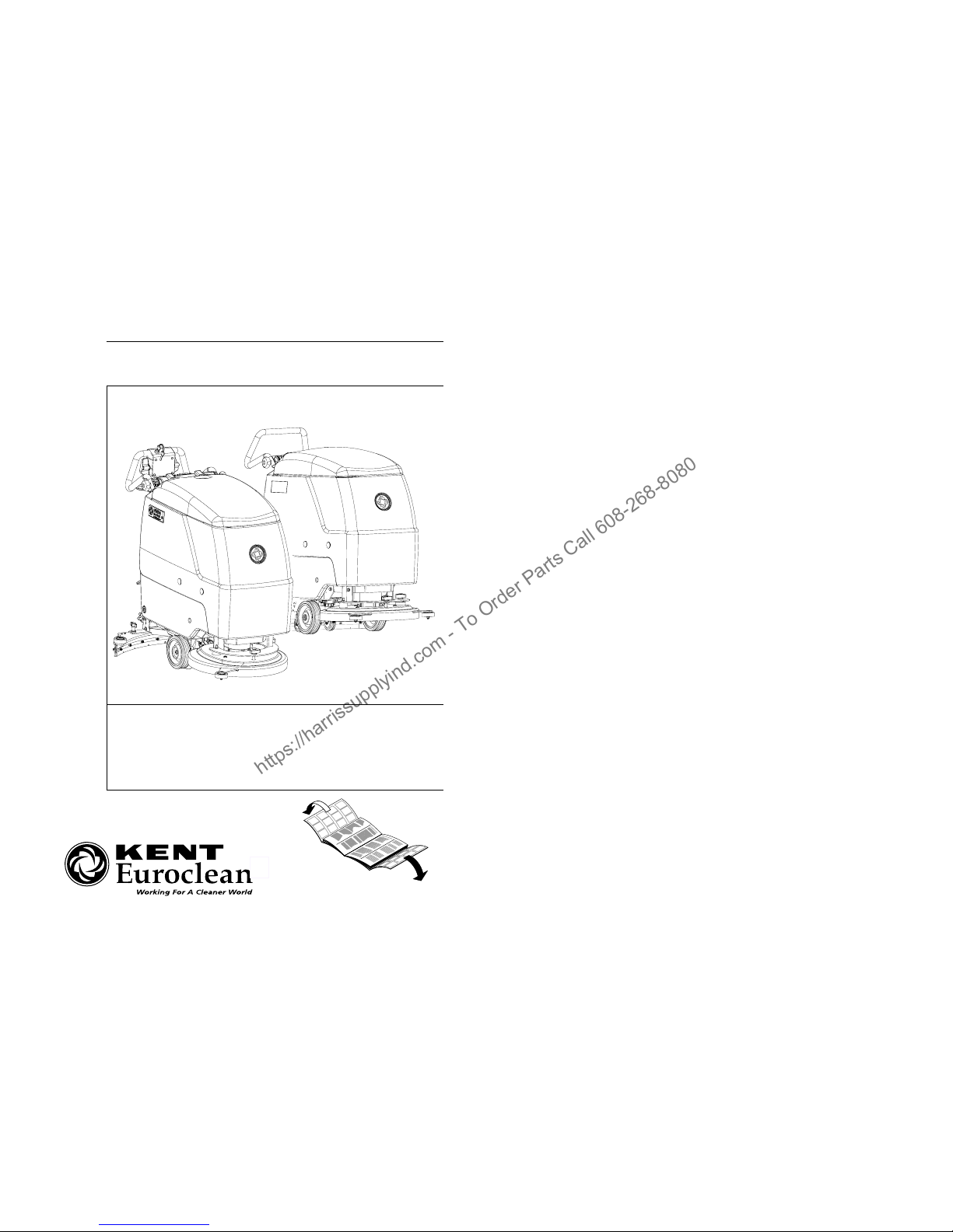
Razor 17B - 20B - 20BT
Razor 17B - 20B - 20BT
08812946(3)2003-08
KENT/Euroclean MODELS:
INSTRUCTIONS FOR USE
English
French
Spanish
Portuguese
908 7010 020 - 908 7011 020 - 908 7025 020
https://harrissupplyind.com - To Order Parts Call 608-268-8080
Page 2
08812946(3)2003-08
B
S310087
C
S310088
D
S310048
E
S310049
https://harrissupplyind.com - To Order Parts Call 608-268-8080
Page 3
08812946(3)2003-08
F
S310163
G
S310159
H
S310089
https://harrissupplyind.com - To Order Parts Call 608-268-8080
Page 4
08812946(3)2003-08
I
S310090
J
S310091
F3
CH1
C1
BU
BN
C1
BKRDBN
V-
V+
IS1
IS2
F2
YE
CFBA430
BKBU BN RD
RD
Charger
EB1
SWITCH
PKWHOGBNBU GY
EB2
SW1
SW2
RD
ES1
RD
BU
ES2
F1
YE
BN
M2
BK
M1
RD
RD
OR WH
EV1
GY
Pb/Gel
SWITCH
F4
M3
SW4
SW3
K1
VT
M-
M+
B-
B+
R1
1
5
8
4
EB3
VT
VT
VT
VT
YEBUWHBN
BN
WH
BU
BK
RD
RD
VT
Kent Euroclean Razor 20BT
+
-
+
-
CT
1
BL
S-BT VT
S+ V-
BL
V+
8
CH
8
SC LRSVSB LY LG
KY
LC
1
Ch
NO Ch
W-
W+
Gel
Pb
F3
CH1
C1
BU
BN
C1
BK
RD
BN
V-
V+
IS1
IS2
F2
YE
CFBA430
BK
BU
BN RD
BK
Charger
EB1
SWITCH
PKWHOG
BN
BU
GY
EB2
SW1
SW2
RD
ES1
RD
BU
ES2
F1
YE
BN
M2
BK
M1
RD
RD
OR WH
EV1
GY
Pb/Gel
SWITCH
Kent Euroclean Razor 17B / 20B
+
-
+
-
CT
1
BL
S-
BT
VT
S+
V-
BL
V+
8
CH
1
SC
LR
SV
SB LY LG
V-
LC
8
Ch
NO Ch
W-
W+
Gel
Pb
© 2003 Printed in Italy
Kent/Euroclean
14600 21st Avenue North
Plymouth, MN, 55447-3408
www.kenteuroclean.com
Phone: 800-334-1083
Fax: 866-261-4779
https://harrissupplyind.com - To Order Parts Call 608-268-8080
Page 5

INSTRUCTION MANUAL FOR USE AND MAINTENANCE
08812946(3)2003-08 1
INTRODUCTION 2
PURPOSE AND CONTENTS OF THIS MANUAL 2
TARGET 2
HOW TO KEEP THIS MANUAL 2
IDENTIFICATION DATA 2
OTHER REFERENCE MANUALS 2
SPARE PARTS AND MAINTENANCE 2
MODIFICATIONS AND IMPROVEMENTS 2
SAFETY - ACCIDENT PREVENTION 2
SYMBOLS 3
GENERAL INSTRUCTIONS 3
UNPACKING 4
MACHINE DESCRIPTION 4
KENT/EUROCLEAN RAZOR 17B - 20B - 20BT AUTOMATIC SCRUBBER OPERATION 4
TECHNICAL DATA 6
DIAGRAMS 7
ELECTRICAL PROTECTIONS 7
ACCESSORIES / OPTIONS 7
USE 8
BATTERY CHECK/SETTING ON A NEW MACHINE 8
BATTERY INSTALLATION AND BATTERY TYPE SETTING (WET OR GEL) 8
BEFORE MACHINE START-UP 9
MACHINE START-UP AND STOP 9
MACHINE OPERATION (WASHING/ DRYING) 10
TANK EMPTYING 10
AFTER MACHINE USE 11
MACHINE LONG INACTIVITY 11
FIRST PERIOD OF USE 11
MAINTENANCE 11
SCHEDULED MAINTENANCE TABLE 11
SQUEEGEE CLEANING 12
SQUEEGEE BLADE CHECK (AND REPLACEMENT) 12
BRUSH CLEANING 12
TANK AND SUCTION GRID WITH FLOAT CLEANING 12
DETERGENT FILTER CLEANING 13
BATTERY CHARGE 13
FUSE CHECK/REPLACEMENT 14
SAFETY FUNCTIONS AND TROUBLESHOOTING 14
SAFETY FUNCTIONS 14
TROUBLESHOOTING 14
SCRAPPING 15
https://harrissupplyind.com - To Order Parts Call 608-268-8080
Page 6

INSTRUCTION MANUAL FOR USE AND MAINTENANCE
2 08812946(3)2003-08
INTRODUCTION
PURPOSE AND CONTENTS OF THIS
MANUAL
The purpose of this manual is to provide the User with
all necessary information to use the machine properly
in a safe and autonomous way. It contains information
about technical characteristics, operation, machine
inactivity, maintenance, spare parts and safety conditions.
Before carrying out any procedure on the machine, the
Operators and Technicians in charge of the maintenance must read this manual carefully. Contact Kent/Euro-
clean Service Center in case of doubts regarding the
interpretation of the instructions and for any further information.
TARGET
This manual is intended for the Operator and the Technicians qualified for the machine maintenance.
HOW TO KEEP THIS MANUAL
The Use and Maintenance Manual must be kept near
the machine, inside an adequate case, far from liquids
and other substances that can cause damage to it.
IDENTIFICATION DATA
The Machine Model and Serial Number are marked
on the plate on the tank and can be read from the
outside. (1, Fig. C).
The machine production year is shown after the Date
Code on the serial plate (A02 means January 2002).
This information is useful when requiring machine replacement parts. Use the following table to write down
the machine identification data for any further reference.
OTHER REFERENCE MANUALS
– Electronic Battery Charger Manual, that is to be
considered as integral part of this manual.
Moreover, the following manuals are available:
– Service Manual (that can be consulted at the
Kent/Euroclean Service Center)
– Spare Part List, supplied with the machine
SPARE PARTS AND MAINTENANCE
All necessary use, maintenance and repair procedures
must be carried out by qualified personnel or by a
Kent/Euroclean Service Center. Only original spare
parts and accessories must be used.
Call Kent/Euroclean for service or to order spare parts
and accessories, specifying the machine Model and
Serial Number.
MODIFICATIONS AND IMPROVEMENTS
Our Company constantly improves its products and reserves the right to make changes and improvements at
its discretion without being obliged to apply such benefits to the machines previously sold.
Any modifications and/or accessory adding must be approved and performed by the Manufacturer.
SAFETY - ACCIDENT PREVENTION
The following symbols indicate potentially dangerous situations. Always read carefully this information and take the necessary precautions to protect
people and objects.
No accident prevention program is effective without the
total cooperation of the person responsible for the machine operation. Most of the accidents that may occur
in a factory, while working or transferring, are caused
by the failure to comply with the simplest prudence rules. A careful and prudent user is the best guarantee
against accidents and is the prerequisite to carry out
the prevention program.
MACHINE model.................................................
MACHINE serial number.......................................
https://harrissupplyind.com - To Order Parts Call 608-268-8080
Page 7
INSTRUCTION MANUAL FOR USE AND MAINTENANCE
08812946(3)2003-08 3
SYMBOLS
GENERAL INSTRUCTIONS
Specific warnings and cautions to inform about potential damages to people and machine are shown below.
– Disconnect the battery by means of the appropriate
connector before carrying out any maintenance or
repair operation.
– This machine must be used by qualified and autho-
rized personnel only. Children or disabled people
cannot use this machine.
– Keep the battery far from sparks, flames and incan-
descent material. During the normal operation
explosive gases are delivered.
– Do not wear jewels when working near electrical
components.
– Do not work under the lifted machine if it is not
securely fixed.
– Do not operate the machine near dangerous, inflam-
mable and/or explosive powders, liquids or vapors.
– Battery charging produces explosive hydrogen gas.
Keep the tank assembly open during battery
charging and perform the operation only in
well-ventilated areas and far from naked flames.
DANGER!
Indicates a dangerous situation (risk of
death) for the User.
WARNING!
Indicates the risk for people of being injured and for objects of being damaged.
CAUTION!
Indicates a caution or a remark related to
important or useful functions. Take care
of the paragraphs marked by this symbol.
!
CONSULTATION
Consult the instruction booklet before
performing a determined operation.
DANGER!
– Carefully read all maintenance/repair instructions
before carrying out any maintenance/repair
procedure.
– Before using the battery charger, be sure that
frequency and voltage values indicated in the
specific Manual correspond to the system
values.
– Take all necessary precautions to prevent hair,
jewels and loose dresses from being caught by the
machine moving and suction parts.
– Do not smoke during battery charging.
– Do not leave the machine unattended without being
sure that the machine cannot move independently.
– Do not use the machine on surfaces with a gradient
greater than the one indicated on the machine.
– Do not wash the machine with pressurized water, or
with corrosive substances.
– Do not use the machine in very dusty areas.
– While using this machine take care not to cause
damage to people.
– Storage temperature must be within 0°C - +40°C.
– The machine working temperature must be within
0°C - +40°C.
– Humidity range should be within 30% and 95%.
– Always protect the machine against the sun, rain and
bad weather, both during operation and inactivity.
– Do not use the machine as a transport vehicle.
– Do not allow the brush to operate while the machine
is stationary to avoid damaging the floor.
– In case of fire, use a powder extinguisher. Do not use
water.
– Do not bump into shelves or scaffoldings, in parti-
cular where there is a risk of falling objects.
– Do not tamper with the machine safety guards; follow
the ordinary maintenance instructions scrupulously.
– Do not remove or modify the plates affixed on the
machine.
– In case of machine malfunctions ensure that these
are not caused by a lack of maintenance. Otherwise,
request assistance from the authorized personnel or
the Service Center.
– If parts must be replaced, require ORIGINAL spare
parts from a Dealer or Authorized Retailer.
– To ensure the machine proper operation and safety
conditions, the authorized personnel or the Service
Center must carry out the Scheduled Maintenance
detailed in the related chapter of this Manual.
– The machine must be disposed of properly, because
of the presence of toxic-harmful materials (battery
acid, oil, etc.), which are subject to standards that
require disposal in special centers (see chapter
“Scrapping”).
WARNING!
https://harrissupplyind.com - To Order Parts Call 608-268-8080
Page 8

INSTRUCTION MANUAL FOR USE AND MAINTENANCE
4 08812946(3)2003-08
– If the machine is used according to the instructions,
the vibrations do not cause dangerous situations.
The machine vibration level is under 2.5 m/s
2
.
– Do not leave any object penetrated in the openings.
Do not use the machine in case the openings are
blocked; always keep the openings free from dust,
bast, hairs and any other foreign body which could
reduce the air flow.
– This machine cannot be used on roads or public
streets.
–Pay attention to the machine transfers when tempe-
rature is under freezing point. The water in the
recovery tank or in the pipes could freeze and
damage the machine.
– Use the brushes and the pads supplied with the
machine and those specified in the Instruction
Manuals. Using other brushes or pads could reduce
safety.
UNPACKING
To unpack the Machine carefully follow the instructions
on the packing.
When the machine is delivered, check that the packing
and the machine were not damaged during transportation. If the damage is evident, keep the packing and
have it checked by the Parcel Service that delivered it.
Call the Parcel Service immediately to fill in a request
for a compensation for damages.
Please check that the following items have been supplied with the machine:
1. Technical documents:
– Instructions for Use
– Electronic Battery Charger Manual
– Spare Part List
2. No. 1 lamellar fuse
MACHINE DESCRIPTION
KENT/EUROCLEAN RAZOR 17B - 20B 20BT AUTOMATIC SCRUBBER OPERATION
The scrubber-dryer is used to clean (washing and
drying) smooth and solid floor, in civil or industrial en-
vironment, under safe operation conditions by a trained Operator.
The scrubber-dryer cannot be used for fitted carpet
and carpet cleaning.
Agreements
Forward, backward, front, rear, left or right are inten-
ded with reference to the operator’s position with the
operator's hands on the handlebar (2, Fig. C).
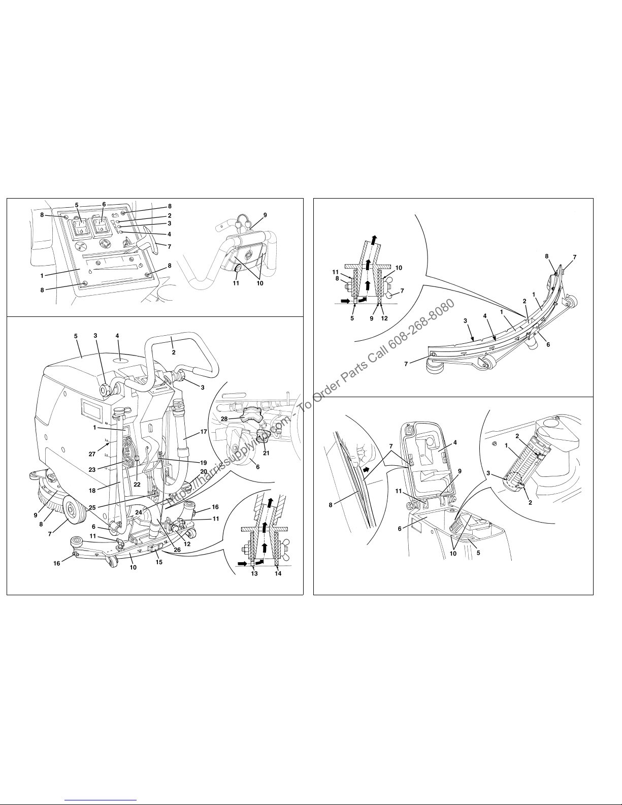
Control panels and commands
(See Fig. B)
1. Control panel and commands
2. Charged battery warning light (green)
3. Semi-discharged battery warning light (yellow)
4. Discharged battery warning light (red)
5. Brush rotation switch
6. Suction switch
7. Detergent flow control lever
8. Control panel and commands mounting screws
9. Key switch (*)
10. Drive control levers (*)
11. Drive speed governor (*)
(*) “20BT” versions only
https://harrissupplyind.com - To Order Parts Call 608-268-8080
Page 9

INSTRUCTION MANUAL FOR USE AND MAINTENANCE
08812946(3)2003-08 5
Exterior rear overview
(See Fig. C)
1. Serial number plate / technical data
2. Handlebar
3. Handlebar inclination adjusting handles
4. Can holder
5. Tank cover
6. Pivoting rear wheels
7. Front wheels on fixed axis
8. Brush, or pad-holder and pad
9. Brush/pad-holder plate
10. Squeegee
11. Squeegee fastening handwheels to the machine
12. Squeegee balance adjusting handwheel
13. Squeegee front blade
14. Squeegee rear blade
15. Rear blade fastening hook
16. Wing nuts
17. Recovery water drain hose
18. Detergent drain hose
19. Squeegee lifting lever
20. Brush lifting pedal
21. Detergent filter
22. Battery charger plug
23. Battery charger cable
24. Supplied key
25. Battery connection connector
26. Squeegee suction hose
27. Detergent tank marks
28. Detergent tap
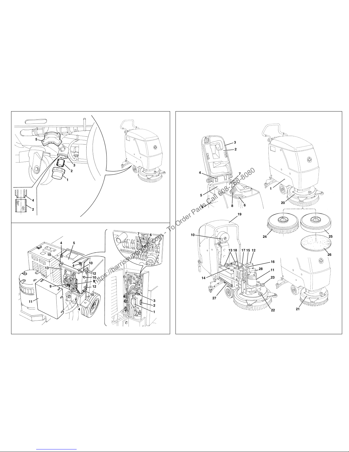
Front under cover and tank exterior overview
(See Fig. H)
1. Tank side fastening screw
2. Tank cover (open position)
3. Tank cover seal
4. Compensation hole
5. Recovery water tank
6. Detergent tank
7. Recovery water suction hole
8. Suction grid with automatic closing with float
9. Recovery water draining hole
10. Suction motor
11. Brush motor
12. Electrical component box
13. Batteries
14. Battery caps
15. Battery assembly diagram
16. Electronic battery charger
17. Charged battery warning light
18. Lead (WET) or gel (GEL) battery selector switch
(positioned on the electronic battery charger)
19. Tank assembly
20. Brush/pad-holder plate (Razor 17B version)
21. Brush/pad-holder plate (Razor 20B version)
22. Machine forward movement adjusting knob
23. Machine forward movement speed adjusting knob
24. Brush
25. Pad-holder
26. Pad
27. Counterbalance
28. Box with traction board and fuses of the drive
system (*)
(*) “20BT” versions only
https://harrissupplyind.com - To Order Parts Call 608-268-8080
Page 10

INSTRUCTION MANUAL FOR USE AND MAINTENANCE
6 08812946(3)2003-08
TECHNICAL DATA
(*) “20BT” versions only
Dimensions Razor 17B Razor 20B - 20BT
Cleaning width 430 mm – 17 in 508 mm – 20 in
Machine length with extended handlebar 1158 mm – 45.6 in 1197 mm – 47.1 in
Machine length with lowered handlebar 1040 mm – 40.9 in 1180 mm – 46.5 in
Machine height with lifted handlebar 1056 mm – 41.6 in
Machine height with lowered handlebar 943 mm – 37.1 in
Machine width without squeegee 508 mm – 20.0 in 519 mm – 20.4 in
Brush diameter 430 mm – 17 in 508 mm – 20 in
Maximum slope 2%
Clean water tank capacity 40 liters – 10.6 gal
Dirty water tank capacity 40 liters – 10.6 gal
Weight without batteries 115,5 kg – 255 lbs
118 kg – 260 lbs (Razor 20B)
126 kg – 278 lbs (Razor 20BT)
Front wheels on fixed axis Ø 170 mm – 6.7 in
Pivoting rear wheels Ø 80 mm – 3.1 in
Suction motor power 500 W
Brush motor power 650 W
Drive motor power (*) 130 W
Brush/Pad Speed 180 RPM
Acoustic pressure level 65 dBA
Standard batteries 2x12V 105 Ah WET
Batteries rated voltage 24 V
Battery compartment size 350x350x300mm – 13.8x13.8x11.8 in
Suction circuit vacuum 1400 mm Water – 55 in Water
https://harrissupplyind.com - To Order Parts Call 608-268-8080
Page 11

INSTRUCTION MANUAL FOR USE AND MAINTENANCE
08812946(3)2003-08 7
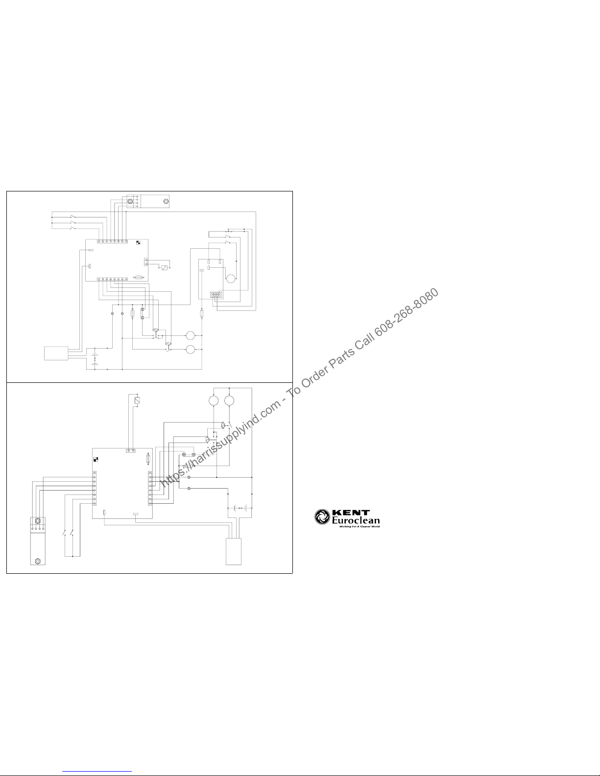
DIAGRAMS
Wiring diagrams, for different optional equipments (see
Fig. I and J);
Legend
CH1 Battery charger
C1 Battery connector
EB1 Electronic board (CFBA430)
EB2 LED board (CFBALED)
EB3 Traction electronic board
ES1 Brush electromagnetic switch
ES2 Vacuum electromagnetic switch
EV1 Water solenoid valve
F1 Brush fuse (50A)
F2 Vacuum fuse (40A)
F3 Water valve & electronic fuse (5A)
F4 Traction fuse (30A)
IS1 Negative insulator
IS2 Positive insulator
K1 Key switch
M1 Brush motor
M2 Vacuum motor
M3 Drive motor
R1 Drive speed governor
SW1 Brush switch
SW2 Vacuum switch
SW3 Traction control micro-switch
SW4 Drive motor micro-switch
Color code
BK Black
BU Blue
BN Brown
GN Green
GY Grey
OG Orange
PK Pink
RD Red
VT Violet
WH White
YE Yellow
ELECTRICAL PROTECTIONS
Fuses
Brush safety fuse (50 A): (1, Fig. G)
Aspirator fuse (40 A): (2, Fig. G)
Solenoid valve fuse (5 A): (3, Fig. G)
Traction fuse (30 A): (8, Fig. G) (*)
Electronic board protection fuse (2A): (9, Fig. G) (*)
(*) “20BT” versions only
Brush motor overload protection electronic system
This system works when the brush motor is overloaded.
Its operation is signaled by the three warning lights
flashing at the same time (2, 3, 4, Fig. B); after a few seconds, the brush motor stops.
In order to restart the motor, it is necessary to eliminate
the cause of the overload, which can be:
– the brush is too much pressed on the floor
– the brush is blocked by floor roughness or by a
foreign body
– the brush rotation is slowed down by dirt, ropes or
rags around its rotation shaft
– the friction between brush and floor is excessive
(increase the detergent quantity by means of the
appropriate adjusting lever (7, Fig. B))
Once the overload cause has been eliminated, reset
the system as indicated here below:
– (20B versions) stop the machine by turning switches
(5 and 6, Fig. B) to "0".
– (20BT versions) stop the machine by turning the
ignition key (9, Fig. B) to "0".
After that, the machine can be restarted again, as described in the related chapter.
Drive motor overload protection electronic system
(20BT versions only)
This system works when the drive motor is overloaded.
Its operation is signalled by the drive motor stopping.
After a while, the system can be reset by stopping the
machine by turning the ignition key (9, Fig. B) to "0".
After that, the machine can be restarted again, as described in the related chapter.
ACCESSORIES / OPTIONS
In addition to the standard components, the machine
can be equipped with the following accessories/options, according the machine specific use:
1. Gel batteries.
2. Brush of materials different from the standard
ones.
3. Pads of two different materials
4. Squeegee oil-proof blades.
For further information concerning the optional accessories apply to an authorized retailer.
https://harrissupplyind.com - To Order Parts Call 608-268-8080
Page 12
INSTRUCTION MANUAL FOR USE AND MAINTENANCE
8 08812946(3)2003-08
USE
By means of this Manual, the operator must learn the
meaning of these symbols.
Do not cover these plates for any reason, in case of damage replace them immediately.
BATTERY CHECK/SETTING ON A NEW
MACHINE
– The electric components of this machine can be
seriously damaged if batteries are either installed or
connected improperly. Batteries can be installed by
qualified personnel only. Set the machine electronic
board and the integrated battery charger according
to the type of batteries used (lead or gel batteries).
– Check the batteries for damage before installation.
– Disconnect the battery connector or the battery
charger plug.
– Move the batteries with great care.
– Be sure that the battery charger cables are properly
connected to the battery terminals according to their
polarity.
– Install the battery terminal protection caps supplied
with the machine.
The machine needs two 12 V batteries, connected ac-
cording to the diagram (15, Fig. H).
The machine can be set in one of the following modes:
a) With (lead or gel) batteries installed on the
machine and ready to be used.
b) With lead batteries installed on the machine but
without liquid electrolyte.
c) Without battery
According to these conditions, operate as described
below.
a) (Lead or gel) batteries supplied and already
installed on the machine and ready to be used.
1. Check that the batteries are connected to the
machine by means of the connector (25, Fig. C).
2. Start the machine by means of the brush and
suction push-buttons (5 and 6, Fig. B). If the green
warning light (2, Fig. B) turns on, the batteries are
ready to be used. If the warning lights (3 or 4, Fig.
WARNING!
On some points of the machine there are
some decals indicating:
- DANGER
- WARNING
- CAUTION
- CONSULTATION
WARNING!
B) turn on, it is necessary to charge the batteries
(see procedure in chapter "Maintenance")
b) Lead batteries supplied and already installed
on the machine but without liquid electrolyte.
1. Remove the key (24, Fig. C) from its housing and
remove the tank assembly fastening screw (1, Fig.
H).
2. Carefully lift the tank assembly (19, Fig. H) by
means of the manoeuver handle (2, Fig. C).
3. Remove the battery caps (14, Fig. H).
4. Fill up each battery element with sulfuric acid for
batteries (density from 1.27 to 1.29 Kg at 25°C) in
accordance with the instructions specified in the
Battery Use and Maintenance Manual.
The correct quantity of sulfuric acid is indicated in
the Battery Use and Maintenance Manual.
5. To avoid damaging the floor, dry with a cloth both
acid and water on the top of the batteries after
charge.
6. Let the batteries rest for a few minutes and fill in
with sulfuric acid in accordance with the instructions specified in the Battery Use and Maintenance Manual.
7. Proceed with recharging the batteries (see the
procedure in the Maintenance paragraph).
c) Without batteries
1. Buy appropriate batteries (See paragraph
"Technical Characteristics" and the diagram 15,
Fig. H).
Apply to battery qualified retailers to choose and
install the battery.
2. Install and set the machine batteries (WET or
GEL) and the battery charged according to the
type of battery, as described in the following
paragraph.
BATTERY INSTALLATION AND BATTERY
TYPE SETTING (WET OR GEL)
According to the chosen battery type (lead or gel) perform the setting of the electronic board of the machine
and the battery charger, operating as indicated below:
WARNING!
Please pay a strict attention when working
with sulfuric acid, as it is corrosive. If it
comes in contact with the skin or the eyes,
wash abundantly with water and call a
doctor.
Batteries have to be filled up in a properly
ventilated area.
Use protective gloves.
https://harrissupplyind.com - To Order Parts Call 608-268-8080
Page 13
INSTRUCTION MANUAL FOR USE AND MAINTENANCE
08812946(3)2003-08 9
Machine setting
1. Ensure that the Battery connector (25, Fig. C) is
completely disconnected.
2. Remove the key (24, Fig. C) from its housing and
remove the tank assembly fastening screw (1, Fig.
H).
3. Carefully lift the tank assembly (19, Fig. H) by
means of the manoeuver handle (2, Fig. C).
4. The machine setting performed at the factory is for
lead (WET) batteries. If the setting corresponds to
the chosen battery, go to step 8, otherwise
perform the operations at points 5, 6, 7.
5. Unscrew the screws (4, Fig. G) and carefully
remove the electric component box cover (5)
making it slide upwards.
6. Move the micro-switch (6, Fig. G) upwards
(dip-switch) to GEL position.
7. Reinstall the electric component box cover (5, Fig.
G) and screw the screws (4).
Battery charger setting
8. Take the battery charger selector (18, Fig. H) to
WET position for lead battery, or to GEL position
for gel battery.
Battery installation and charge
9. Install the batteries on the machine according to
the diagram (15, Fig. H).
10. Proceed with recharging the batteries (see the
procedure in the paragraph "Maintenance").
BEFORE MACHINE START-UP
Brush or pad-holder installation
1. Lift the brush-holder (9, Fig. C) by means of the
pedal (20, Fig. C).
WARNING!
Do not move the adjacent switch (7, Fig.
G).
NOTE:
Battery charger must be connected to the
batteries for machine to function.
REMARK:
Depending on the type of floor, either a
brush (24, Fig. H) or a pad-holder (25)
with pad (26) can be installed.
To simplify, the following instructions
refer to the brush only.
2. Position the brush (24, Fig. H) under the
brush-holder.
3. Lower the brush-holder (9, Fig. C) by means of the
pedal (20, Fig. C).
4. (20BT versions only): Turn the key (9, Fig. B) to "I"
5. Press the brush push-button for a few seconds (5,
Fig. B) to hook the brush/pad-holder.
Squeegee installation
6. Install the squeegee into place (10, Fig. C) and fix
the handwheels (11), then connect the hose (26)
to the squeegee.
7. Adjust the squeegee by means of the handwheel
(12, Fig. C) so that its rear blade (14, Fig. C) - in
all its length - touches the floor and that the front
blade (13) is slightly detached from the floor.
Adjustments
8. Adjust the handlebar (2, Fig. C) by means of the
handles (3), to reach a comfortable position.
Detergent tank filling up
9. Open the cover (2, Fig. H) of the tanks.
10. Fill the detergent tank (6, Fig. H) with an appropriate detergent, depending on the cleaning to be
carried out.
It is possible to check the tank filling up by means
of the marks (27, Fig. C).
Do not fill the detergent tank completely and let
the detergent level a few centimeters from the rim.
Always follow the dilution instructions on container
label of the chemical product used to create the
detergent solution.
The detergent temperature must be under 40°C
(100°F).
MACHINE START-UP AND STOP
Machine start-up
1. Prepare the machine as described in the previous
paragraph.
2. Lower the squeegee (10, Fig. C) by means of the
lever (19).
3. Lower the brush (8, Fig. C) by means of the pedal
(20).
CAUTION!
Use only low-foam and non-flammable
detergent liquids, appropriate to the
use.
https://harrissupplyind.com - To Order Parts Call 608-268-8080
Page 14
INSTRUCTION MANUAL FOR USE AND MAINTENANCE
10 08812946(3)2003-08
4. Position the detergent flow adjusting lever (7, Fig.
B) in the most appropriate position, depending on
the type of cleaning to be carried out.
5. Keep a hand on the handlebar (2, Fig. C), start the
machine by means of the brush and suction
push-buttons (5 and 6, Fig. B).
Machine stop
6. Position the brush and suction push-buttons on
"0" (5 and 6, Fig. B).
7. Lift the brush by means of the pedal (20, Fig. C).
8. Lift the squeegee by means of the lever (19, Fig.
C).
9. (20BT versions only): Turn the key (9, Fig. B) to
"0".
MACHINE OPERATION (WASHING/
DRYING)
1. Start the machine as described in the previous
paragraph.
2. Keep both hands on the handlebar (2, Fig. C),
manoeuver the machine and start the floor
washing/drying.
(20BT versions only): By pressing the levers (10, Fig.
B), both clockwise than counterclockwise, the machine
feeds forward; reverse feed is not performed.
Traverse speed can be adjusted by turning the adjuster
(11, Fig. B).
To pull the machine backwards or to perform turns with
a very narrow radius, the traverse control has to be disconnected by releasing the levers (10, Fig. B).
REMARK:
If the green warning light (2, Fig. B)
turns on, the machine is ready to be
used. If the yellow or red warning lights
(3 or 4, Fig. B) turn on, it is necessary to
charge the batteries (see procedure in
chapter "Maintenance").
CAUTION!
To avoid any damage to the floor surface, stop the brush rotation by means
of the switch (5, Fig. B) when the machine stops in one place.
CAUTION!
Before lifting the brush/pad-holder,
stop its rotation by means of the switch
(5, Fig. B).
Machine traction controls
3. Depending on the floor type, or on the use of the
brush or the pad-holder, the machine front traction
speed and the forward straightaway movement
(without turning on the right or on the left) can
change.
They can be adjusted by means of two knobs (22
and 23, Fig. H) on the brush-holder, proceeding in
the following way:
– The machine moves towards the left by
turning the adjusting knob counter-clockwise
(22, Fig. H); the machine moves towards the
right turning the knob clockwise.
– The machine speed increases by turning the
adjusting knob counter-clockwise (23, Fig.
H); the machine speed decreases turning the
knob clockwise.
TANK EMPTYING
Once the recovery water tank (5, Fig. H) is full, empty it
in the following way.
Recovery water tank emptying
1. Stop the machine by means of the brush and
suction push-buttons (5 and 6, Fig. B).
2. Lift the brush/pad-holder by means of the pedal
(20, Fig. C).
3. Lift the squeegee by means of the lever (19, Fig.
C).
4. Push the machine to the appointed disposal area.
5. Empty the recovery tank by means of the hose
(17, Fig. C). If at the end of the work, rinse the tank
with clean water.
Detergent tank emptying
6. Carry out steps from 1 to 4.
7. Empty the detergent tank by means of the hose
(18, Fig. C). If at the end of the work, rinse the tank
with clean water.
REMARK:
A float automatic closing system (8,
Fig. H) locks the suction system once
the recovery tank (5) is full.
The suction system locking, caused by
the water tank filling up, is signaled by
a sudden increase in the aspirator motor noise frequency.
https://harrissupplyind.com - To Order Parts Call 608-268-8080
Page 15
INSTRUCTION MANUAL FOR USE AND MAINTENANCE
08812946(3)2003-08 11
AFTER MACHINE USE
At the end of the work, before leaving the machine:
1. Disconnect the brush in the following way:
the brush lifted, push the brush switch (5, Fig. B)
to on position "I"; after a few seconds, put the
switch back to off position "0", releasing the brush.
2. Empty the tanks (5 and 6, Fig. H), following the
instructions in the previous paragraph.
3. Perform the maintenance operations after the
machine use (see chapter "Maintenance").
4. Leave the machine in a dry and clean place, with
brush and squeegee lifted or removed.
MACHINE LONG INACTIVITY
If you foresee that the machine will not be used for
more than 30 days, proceed as follows:
1. Perform the operations described in the previous
chapter "After Machine Use".
2. Disconnect the battery connector (25, Fig. C).
3. Disconnect the positive battery terminal (+)
directly from the battery (+) pole.
FIRST PERIOD OF USE
After the first period of use (first 8 hours) it is necessary
to check that the fixing and connecting elements are
correctly fixed, that the visible parts are integral and
that there are no leaks.
MAINTENANCE
The machine proper and safe operation is guaranteed
by a careful and constant maintenance.
The following table sums up the scheduled maintenance. The indicated periods can be subjected to variations according to working conditions. These must be
defined by the person in charge for the maintenance.
All periodic or extraordinary maintenance operations
must be performed by skilled personnel, or by an authorized Service Center.
This Manual contains the Scheduled Maintenance Table and describes only the easiest and most common
maintenance procedures.
WARNING!
The operations must be carried out with
the machine off and the battery disconnected.
Moreover, read carefully the instructions in the Safety chapter before performing any maintenance operation.
REMARK:
For other maintenance procedures contained in the Scheduled Maintenance
Table see the specific “Service Manual”
that can be consulted at the Kent/Euroclean Service Center.
SCHEDULED MAINTENANCE TABLE
(1): and after the first 8 working hours
(2): contact the Kent/Euroclean Service Center for these maintenance operations
(*): 20BT versions only
Operation
Daily, after
machine use
Weekly
Every six
months
Yearly
Squeegee cleaning "
Squeegee blade check (and replacement) "
Brush cleaning "
Tank and suction grid with float cleaning "
Detergent filter cleaning "
Battery charge "
Lead battery (WET) liquid level check "
Nut and screw tightening check " (1)
Brush electric motor carbon brush check or replacement " (2)
Suction electric motor carbon brush check or replacement " (2)
Drive motor brush (or carbon brush) check or replacement (*) " (2)
Grease drive shaft bearings (*) "
https://harrissupplyind.com - To Order Parts Call 608-268-8080
Page 16
INSTRUCTION MANUAL FOR USE AND MAINTENANCE
12 08812946(3)2003-08
SQUEEGEE CLEANING
1. Drive the machine to a level surface.
2. Check the switches (5 and 6, Fig. B) are in the "0"
position.
3. Lower the squeegee (10) by means of the lever
(19, Fig. C).
4. Disconnect the suction hose (26, Fig. C) from the
squeegee.
5. Loosen the handwheels (11, Fig. C) and remove
the squeegee (10).
6. Wash and clean the squeegee; in particular, clean
the compartments (1, Fig. D) and the hole (2) from
dirt and debris. Check that the front (3) and rear
blades (4) are integral and free from cuts and
lacerations; otherwise replace them (see
procedure in the following paragraph).
7. Install in the reverse order of removal.
SQUEEGEE BLADE CHECK (AND
REPLACEMENT)
1. Clean the squeegee (as described in the previous
paragraph).
2. Check that the edges (5, Fig. D) of the front and
rear blades (12) lay down on the same level, along
all their length; otherwise adjust their height as
described below:
– disengage the retainer (6) and loosen the
wing nuts (7) to adjust the rear blade (4); then
tighten the wing nuts and engage the
retainer.
– loosen the nuts (8) to adjust the front blade
(3); then tighten the nuts.
3. Check that the front and rear blades (3 and 4) are
integral and free from cuts and lacerations;
otherwise replace them as described below.
Check that the front corner (9) of the rear blade is
not worn; otherwise, overturn the blade to replace
the worn corner with an integral one. If the other
corners are worn too, replace the blade as
described below:
– To replace (or overturn) the rear blade (4)
disengage the retainer (6), unscrew the wing
nuts (7) and the retaining strip (10). Install in
the reverse order of removal.
REMARK:
The squeegee must be clean and its
blades must be in good conditions in order to get a good drying.
CAUTION!
It is advisable to use protective gloves
when cleaning the squeegee because
there can be cutting debris.
– To replace the front blade (3) remove the nuts
(8) and the retaining strip (11). Install in the
reverse order of removal.
After the blade replacement (or overturning),
adjust their height as described at the
previous step.
4. Reinstall the squeegee assembly (10, Fig. C) in
the correct position and screw down the
handwheels (11).
5. Connect the suction hose (26, Fig. C) to the
squeegee (10).
6. If necessary, adjust the balancing handwheel (12,
Fig. C) of the squeegee.
BRUSH CLEANING
1. Remove the brush, as described in the chapter
"Use".
2. Clean and wash the brush with water and
detergent.
3. Check that the brush bristles are integral and not
excessively worn, otherwise replace the brush.
TANK AND SUCTION GRID WITH FLOAT
CLEANING
1. Push the machine to the appointed disposal area.
2. Check the switches (5 and 6, Fig. B) are in the "0"
position.
3. Lift the cover (2, Fig. H), clean and wash with
clean water the cover (4, Fig. E), the tanks (5 and
6) and the screen (1) of the suction automatic
closing.
Drain the water from the tanks by means of the
hoses (17 and 18, Fig. C).
4. If necessary, release the retainers (2, Fig. E) and
open the screen (1); recover the float (3), clean all
the components and then reinstall them.
5. Check that the tank cover gasket (7) is integral.
If necessary replace the gasket (7) after removing it
from its housing (8). When assembling the new gasket,
install its joint (9) in the (central) area as shown in the
figure.
6. Check that the gasket (7) bearing surface (10) is
integral and adequate for the gasket.
CAUTION!
It is advisable to use protective gloves
when cleaning the brush because there
can be cutting debris.
REMARK:
The gasket (7) creates vacuum in the
tank that is necessary for the suction of
recovery water.
https://harrissupplyind.com - To Order Parts Call 608-268-8080
Page 17
INSTRUCTION MANUAL FOR USE AND MAINTENANCE
08812946(3)2003-08 13
7. Check that the compensation hole (11, Fig. E) is
not obstructed.
8. Close the cover (4, Fig. E).
DETERGENT FILTER CLEANING
1. Rotate and close the detergent tap (5, Fig. F). If
the tap is not fitted on the machine, it’s necessary
empty the tank (6, Fig. H) as described in the
specific paragraph.
2. Drive the machine to a level surface.
3. Check the switches (5 and 6, Fig. B) are in the "0"
position.
4. Operating on the right lower side of the machine,
remove the transparent cover (1, Fig. F) and the
wire gauze (2), clean and reinstall them on the
support (3).
BATTERY CHARGE
REMARK:
The hole (11, Fig. E), allowing to compensate the air in the cover interspaces,
contributes to create vacuum in the
tank.
REMARK:
The wire gauze (2) must be correctly positioned on the support (3) housing (4).
REMARK:
Charge the batteries when the warning
light (3 or 4, Fig. B) turns on and at the
end of every cleaning.
Keeping the batteries charged makes
their life last longer.
CAUTION!
When the batteries are discharged, recharge them as soon as possible, as
that condition makes their life shorter.
Check for battery charge at least once a
week.
1. Drive the machine to a level surface.
2. Remove the key (24, Fig. C) from its housing and
remove the tank assembly fastening screw (1, Fig.
H).
3. Carefully lift the tank assembly (19, Fig. H) by
means of the manoeuver handle (2, Fig. C).
4. For lead batteries only:
– check the correct level of electrolyte inside
the battery; if necessary, top up through the
caps (14, Fig. H).
– leave the caps (14) open for next recharging.
– clean (if necessary) the upper surface of the
battery.
5. Proceed with recharging the battery in the
following way.
Battery charging with battery charger installed on
the machine
1. For lead batteries only:
– check the correct level of electrolyte inside
the battery; if necessary, top up through the
caps (14, Fig. H).
– when the correct level is reached, close the
caps (14) and clean (if necessary) the upper
surface of the battery.
2. Connect the battery charger plug (22, Fig. C) to
the electrical system (the system voltage and
frequency must be compatible with the battery
charger values: see the Battery Charger Manual).
WARNING!
Battery charging produces explosive
hydrogen gas. Charge the batteries
only in well-ventilated areas and far
from naked flames.
Do not smoke during battery charging.
Keep the tank assembly open while recharging the battery.
WARNING!
Pay attention during battery recharging
because there can be battery liquid
leaks. The battery liquid is corrosive. If
it comes in contact with the skin or
eyes, rinse thoroughly with water and
consult a physician.
https://harrissupplyind.com - To Order Parts Call 608-268-8080
Page 18
INSTRUCTION MANUAL FOR USE AND MAINTENANCE
14 08812946(3)2003-08
3. When the red warning light (4, Fig. B) turns off, the
battery charging is completed.
4. Once the battery charging is completed,
disconnect the battery charger plug (22, Fig. C)
from the electric system and hook it to its housing
on the machine.
5. Carefully lower the tank assembly (19, Fig. H) by
means of the manoeuver handle (2, Fig. C).
6. Remove the key (24, Fig. C) from its housing and
remove the tank assembly fastening screw (1, Fig.
H).
7. Now the machine is ready to be used.
FUSE CHECK/REPLACEMENT
1. Disconnect the battery connector (25, Fig. C ).
2. Drain the water from the tanks (5 and 6, Fig. H) by
means of the hoses (17 and 18, Fig. C).
3. Remove the key (24, Fig. C) from its housing and
remove the tank assembly fastening screw (1, Fig.
H).
4. Carefully lift the tank assembly (19, Fig. H) by
means of the manoeuver handle (2, Fig. C).
5. 20BT versions only: loosen the screws (10, Fig.
G) and remove the cover (11).
6. 20BT versions only: check/replace the fuses:
– traction fuse (30A): (8, Fig. G)
– electronic board protection fuse (2A): (9, Fig.
G).
7. 20BT versions only: loosen the wing nuts (12, Fig.
G) and move to one side the support with the
traction electronic board (13, Fig. G).
8. Unscrew the screws (4, Fig. G) and carefully
remove the electric component box cover (5)
making it slide upwards.
9. Check/replace the fuses:
– Brush safety fuse (50 A): (1, Fig. G)
– Aspirator fuse (40 A): (2, Fig. G)
– Solenoid valve fuse (5 A): (3, Fig. G)
10. Install in the reverse order of removal.
REMARK:
When the battery charger is connected
to the electrical system, all machine
functions are automatically cut off.
When the red warning light (4, Fig. B) on
the control panel turns on, it shows that
the battery charger is charging the batteries.
REMARK:
For further information about the battery charger operation (16, Fig. H), see
the related Manual.
SAFETY FUNCTIONS AND
TROUBLESHOOTING
SAFETY FUNCTIONS
The red connector (25, Fig. C) can be used in case of
emergency to stop all the machine functions. If necessary, remove the connector by means of the red handle.
TROUBLESHOOTING
(*):20BT versions only
TROUBLE POSSIBLE CAUSE
Motors do not work: no warning
light turns on
Disconnected battery connector (25,
Fig.C)
Completely discharged batteries
The aspirator motor does not
start
Burnt fuse
Insufficient dirty water suction
Full recovery tank (5, Fig. H)
Obstructed suction grid (8, Fig. H) or
stuck closed float
Disconnected hose (26, Fig. C) from
the squeegee
Dirty squeegee or worn or damaged
squeegee blades
Incorrectly closed tank cover, or
damaged gasket (7, Fig. E) or
obstructed compensation hole (11,
Fig. E)
Insufficient detergent flux to the
brush
Dirty detergent filter (2, Fig. F)
Dirty tank (6, Fig. H) (obstructed
output hole)
Squeegee-provoked lining
Debris under the squeegee blades
Worn, chipped or torn squeegee
blades
Not handwheel-balanced squeegee
(12, Fig. C)
The traction does not operate
(*)
Disconnected battery connector (25,
Fig. C)
Key (9, Fig. B) positioned to "0"
Speed governor (11, Fig. B) is turned
completely counterclockwise
Blown traction fuse (8, Fig. G)
Electronic board malfunction due to
overload or overheat; wait at least 5
minutes before resetting the system
by turning the key (9, Fig. B)
REMARK:
In case of battery charger malfunction,
contact the Kent/Euroclean Service Center.
https://harrissupplyind.com - To Order Parts Call 608-268-8080
Page 19
INSTRUCTION MANUAL FOR USE AND MAINTENANCE
08812946(3)2003-08 15
For further information consult the Service Manual at
the Kent/Euroclean Service Center.
SCRAPPING
Have the machine scrapped by a qualified dismantler.
Before scrapping the machine, remove the following
components
– Battery
–Brush
–Pad
– Electric motors
– Electronic board
CAUTION!
The removed components must be disposed of properly according to Regulations.
https://harrissupplyind.com - To Order Parts Call 608-268-8080
Page 20
INSTRUCTION MANUAL FOR USE AND MAINTENANCE
16 08812946(3)2003-08
https://harrissupplyind.com - To Order Parts Call 608-268-8080
Page 21

MODE D’EMPLOI ET D’ENTRETIEN
08812946(3)2003-08 17
INTRODUCTION 18
BUT ET CONTENU DU MANUEL 18
DESTINATAIRES 18
CONSERVATION DU MANUEL 18
DONNEES D'IDENTIFICATION 18
AUTRES MANUELS DE REFERENCE 18
PIECES DE RECHANGE ET ENTRETIEN 18
MODIFICATIONS ET AMELIORATIONS 18
SECURITE 18
SYMBOLES UTILISES 18
INSTRUCTIONS GENERALES 19
DEBALLAGE 20
DESCRIPTION DE LA MACHINE 20
CAPACITES OPERATIONNELLES AUTOLAVEUSES KENT/EUROCLEAN RAZOR 17 B - 20B - 20BT 20
CARACTERISTIQUES TECHNIQUES 22
PROTECTIONS ELECTRIQUES 23
ACCESSOIRES/OPTIONS 23
UTILISATION 24
CONTROLE / PREPARATION DE LA BATTERIE SUR UNE MACHINE NOUVELLE 24
INSTALLATION DES BATTERIES ET ETABLISSEMENT DU TYPE DE BATTERIE (WET OU GEL) 25
AVANT LA MISE EN MARCHE 25
DEMARRAGE ET ARRET DE LA MACHINE 26
MACHINE AU TRAVAIL (LAVAGE / SECHAGE) 26
VIDAGE RESERVOIRS 27
APRES L'UTILISATION DE LA MACHINE 27
INACTIVITE PROLONGEE DE LA MACHINE 27
PREMIERE PERIODE D'UTILISATION 27
ENTRETIEN 27
PLAN D'ENTRETIEN PROGRAMME 28
NETTOYAGE DE L'EMBOUCHURE 29
CONTROLE (ET REMPLACEMENT) DES ELEMENTS EN CAOUTCHOUC DE L'EMBOUCHURE 29
NETTOYAGE DE LA BROSSE 29
NETTOYAGE DES RESERVOIRS ET DE LA GRILLE D'ASPIRATION AVEC FLOTTEUR 29
NETTOYAGE DU FILTRE DE LA SOLUTION DETERGENTE 30
CHARGEMENT DES BATTERIES 30
CONTROLE / REMPLACEMENT FUSIBLES 31
FONCTIONS DE SECURITE ET DEPISTAGE DES PANNES 32
FONCTIONS DE SECURITE 32
DEPISTAGE DES PANNES 32
MISE A LA FERRAILLE 32
https://harrissupplyind.com - To Order Parts Call 608-268-8080
Page 22

MODE D’EMPLOI ET D’ENTRETIEN
18 08812946(3)2003-08
INTRODUCTION
BUT ET CONTENU DU MANUEL
Ce Manuel se propose de fournir à l'Utilisateur toutes
les informations nécessaires afin qu’il puisse utiliser la
machine correctement et la gérer dans la manière la
plus autonome et sûre. Il comprend des informations
relatives à l’Aspect Technique, le Fonctionnement, l’Arrêt de la Machine, l’Entretien, les Pièces de Rechange
et la Sécurité.
Avant d’effectuer toute opération sur la Machine, les
Opérateurs et les Techniciens chargés de l'Entretien
doivent lire attentivement les instructions contenues
dans ce texte. En cas de doutes sur la correcte interprétation des instructions, contacter un Service
Après-vente Kent/Euroclean, pour avoir plus de renseignements.
DESTINATAIRES
Ce manuel s’adresse à l’Opérateur aussi bien qu’aux
Techniciens préposés à l’Entretien de la machine.
CONSERVATION DU MANUEL
Le Manuel d'Emploi et d'Entretien doit être gardé près
de la machine, dans une enveloppe spéciale et, surtout, loin de liquides et de tout ce qui pourrait en compromettre l’état de lisibilité.
DONNEES D'IDENTIFICATION
Le Numéro de Série et le Modèle de Votre Machine
sont marqués sur la plaquette appliquée sur le réservoir et lisible de l'extérieur. (1, Fig. C).
L’année de fabrication de Votre machine est indiquée
après le code de la date sur le numéro de série de la
machine. (A02 signifie janvier 2002)
Ces informations sont nécessaires lors de la commande des pièces de rechange pour la machine. Utiliser
l'espace ci-dessous pour noter les données d'identification de Votre machine pour une référence future.
AUTRES MANUELS DE REFERENCE
– Manuel d’utilisation du chargeur de batterie électro-
nique, si équipé, qui constitue une partie intégrante
de ce manuel.
En outre les suivants manuels sont disponibles :
Modèle MACHINE....................................................
Numéro de série MACHINE.....................................
– Manuel d’entretien consultable chez les Services
Après-vente
– Catalogue des pièces de rechange, équipé avec la
machine
PIECES DE RECHANGE ET ENTRETIEN
Pour toute nécessité concernant l’utilisation, l’entretien
et les réparations, si nécessaires, il faut s’adresser au
personnel qualifié ou directement aux Centres de Ser-
vice Après-vente Kent/Euroclean, mentionnés à la
fin de ce Manuel, et il ne faut utiliser que des pièces de
rechange et accessoires originaux.
Pour l’assistance ou la commande de pièces de rechange et accessoires, contacter l'organisation
Kent/Euroclean en spécifiant toujours le Modèle et le
Numéro de série.
MODIFICATIONS ET AMELIORATIONS
Notre entreprise vise à un constant perfectionnement
de nos produits et se réserve le droit d’effectuer des
modifications et des améliorations, si nécessaires,
sans l’obligation de sa part de modifier les machines
déjà vendues.
Il est entendu que toute modification et/ou addition
d’accessoires doit toujours être approuvée et réalisée
par le Fabricant.
SECURITE
Nilfisk utilise la symbologie suivante pour signaler
les conditions de danger
potentielles. Lire toujours
ces informations avec attention et prendre les
précautions nécessaires pour protéger les
personnes et les choses.
Aucun programme de prévention des accidents du travail ne peut résulter efficace sans la totale collaboration
de la personne directement responsable du fonctionnement de la machine. La plupart des accidents qui peuvent survenir dans une entreprise, pendant le travail ou
les déplacements, sont dus à l’inobservance des plus
simples règles de prudence. Un utilisateur attentif et
prudent est la meilleure garantie contre les accidents
du travail et se révèle indispensable pour compléter
n’importe quel programme de prévention.
SYMBOLES UTILISES
DANGER !
Indique un danger qui comporte des
risques, même la mort, pour l’Utilisateur.
https://harrissupplyind.com - To Order Parts Call 608-268-8080
Page 23

MODE D’EMPLOI ET D’ENTRETIEN
08812946(3)2003-08 19
INSTRUCTIONS GENERALES
Les avertissements et précautions spécifiques suivants
informent sur les potentiels dangers de dommage à la
machine ou aux personnes.
– Débrancher la batterie avant d'effectuer toute
opération d'entretien/réparation au moyen du
connecteur approprié.
– Cette machine doit être utilisée exclusivement par un
personnel formé et autorisé. L’utilisation de la
machine est interdite aux enfants et aux personnes
handicapées.
– Tenir les étincelles, les flammes et les matériaux
incandescents à distance des batteries. Des gaz
tonnants fuient pendant l'utilisation ordinaire.
– S'enlever tous les bijoux lorsqu'on travaille près de
composants électriques.
– Ne pas travailler sous la machine soulevée, sans
des supports fixes de sécurité convenables.
– Ne pas opérer avec cette machine en présence de
poudres, liquides ou vapeurs nuisibles, dangereux,
inflammables et/ou tonnants.
– En chargeant les batteries un gaz hydrogène très
tonnant est produit. Garder le groupe réservoirs en
position ouverte pendant le cycle de rechargement
des batteries et effectuer l’opération exclusivement
en milieux bien aérés et loin de flammes libres.
ATTENTION !
Il est utilisé pour avertir de l'exposition
à un risque d'accident pour les personnes ou d'endommagement pour les objets.
AVERTISSEMENT !
Indique un avertissement ou une
remarque sur des fonctions clé ou
utiles. Prêter la plus grande attention
aux segments de texte marqués par ce
symbole.
!
CONSULTATION
Le Manuel d'Instructions doit être consulté avant toute opération.
DANGER !
– Avant d'effectuer toute activité d'entretien/
réparation, lire avec attention toutes les instructions
qui concernent l'entretien/réparation.
– Avant d'utiliser le chargeur de batterie, s'assurer
que la fréquence et la tension indiquées dans le
Manuel du chargeur de batterie coïncident avec
les valeurs du réseau.
– Prendre les précautions convenables afin que les
cheveux, les bijoux, les parties non adhérentes des
vêtements ne soient pas capturés par les parties en
mouvement de la machine.
– Ne pas fumer pendant le chargement des batteries.
– Ne pas laisser la machine sans surveillance et
s'assurer que la machine ne peut pas bouger de
façon autonome.
– Ne pas utiliser sur des surfaces dont le gradient est
supérieur au gradient indiqué sur la machine.
– Ne pas laver la machine avec des jets d’eau directs
ou sous pression ou avec des substances corro-
sives.
– Ne pas utiliser la machine dans des milieux particu-
lièrement poussiéreux.
– Pendant l'utilisation de cette machine, faire attention
à sauvegarder l'intégrité des autres personnes.
– La température de stockage doit être comprise entre
0°C et +40°C.
– La température de travail de la machine doit être
comprise entre 0°C et +40°C.
– L’humidité doit être comprise entre 30% et 95%.
– Protéger toujours la machine du soleil, pluie et
d’autres intempéries, et pendant le fonctionnement
et en état d’arrêt.
– Ne pas utiliser la machine comme moyen de
transport.
– Ne pas faire travailler la brosse lorsque la machine
est arrêtée pour ne pas endommager le plancher.
– En cas d’incendie utiliser un extincteur à poudre. Ne
pas utiliser d’eau.
– Ne pas heurter contre des étagères ou des échafau-
dages, en particulier en présence de danger de
chute d’objets.
– Ne pas altérer pour aucune raison les protections
prévues pour la machine, respecter scrupuleu-
sement les instructions prévues pour l’entretien
ordinaire.
– Ne pas enlever ou altérer les plaquettes placées sur
la machine.
– S'assurer que les éventuelles anomalies de fonction-
nement de la machine ne dépendent pas du manque
d'entretien. En cas contraire demander l'intervention
de personnel autorisé ou d'un Service Après-vente
autorisé.
– En cas de remplacement de pièces demander les
pièces de rechange D’ORIGINE à un Concession-
ATTENTION !
https://harrissupplyind.com - To Order Parts Call 608-268-8080
Page 24

MODE D’EMPLOI ET D’ENTRETIEN
20 08812946(3)2003-08
naire ou Revendeur autorisé. Afin de garantir la
sécurité et le bon fonctionnement de la machine,
faire effectuer l'entretien programmé prévu par le
chapitre spécifique de ce Manuel par le personnel
autorisé ou par un Service Après-vente autorisé.
– La machine ne doit pas être abandonnée lors de la
mise à la ferraille, à cause de la présence de
matériaux toxiques (batteries, etc.), sujets à des lois
qui prévoient l’écoulement auprès de centres
spéciaux (voir à ce propos le chapitre Mise à la
ferraille).
– En conditions d’emploi conformes aux indications
d’utilisation correcte, les vibrations ne provoquent
pas de situations de danger. Le niveau de vibrations
de la machine est inférieur à 2,5 m/s
2
.
– Ne pas laisser entrer d'objets dans les ouvertures.
Ne pas utiliser la machine si les ouvertures sont
bloquées; garder les ouvertures de la machine libres
de poussière, filasse, poils et tout autre corps
étranger à même de réduire le flux d'air.
– Cette machine n'est pas approuvée pour l'utilisation
sur les rues publiques.
–Faire attention pendant les déplacements de la
machine en conditions de températures inférieures
au point de congélation. L'eau présente dans le
réservoir de récupération ou dans les tuyaux pourrait
se congeler et endommager sérieusement la
machine.
– Utiliser les brosses et les disques équipés et ceux
spécifiés par les Manuels d'Instruction. L'utilisation
d'autres brosses ou disques peut compromettre la
sécurité.
DEBALLAGE
Pour déballer la machine respecter attentivement les
instructions indiquées sur l'emballage.
Lors de la livraison de la machine, contrôler attentivement que l’emballage et la machine n’ont pas été endommagés pendant le transport. Si le dommage est
évident, garder l’emballage de façon qu’il puisse être
visionné par le Transporteur qui l'a livré. Le contacter
immédiatement pour remplir une demande de dommages-intérêts.
Contrôler que les composants suivants se trouvent toujours avec Votre machine :
1. Documentation technique:
– Manuel d'Emploi et d'Entretien de l'autola-
veuse
– Manuel d'Emploi et d'Entretien du chargeur
de batterie électronique
– Catalogue de pièces de rechange
2. N°1 fusible lamellaire
DESCRIPTION DE LA MACHINE
CAPACITES OPERATIONNELLES
AUTOLAVEUSES KENT/EUROCLEAN
RAZOR 17 B - 20B - 20BT
L'autolaveuse est conçue et fabriquée pour le nettoyage (lavage et séchage) de planchers lisses et solides,
en milieux civils et industriels, en conditions de complète sécurité, par un Opérateur qualifié.
L'autolaveuse n'est pas adapte pour le lavage de tapis
ou moquettes.
Conventions
Toutes les références à en avant, en arrière, avant,
droite, gauche ou arrière indiquées dans ce manuel
doivent être considérées comme référées à l'opérateur
en position de conduite, les mains sur le guidon (2, Fig.
C).
Tableau de bord et commandes
(Voir Fig. B)
1. Tableau de bord et commandes
2. Témoin lumineux de batterie chargée (vert)
3. Témoin lumineux de batterie presque complètement déchargée (jaune)
4. Témoin lumineux de batterie déchargée (rouge)
5. Interrupteur de rotation brosse
6. Interrupteur d'aspiration
7. Levier de réglage flux de solution détergente
8. Vis de fixation du tableau de bord et des
commandes
9. Clé de mise en marche (*)
10. Leviers de commande de traction (*)
11. Régulateur de vitesse de traction (*)
(*) Seulement pour modèles BA 430S D / BA 510S D
https://harrissupplyind.com - To Order Parts Call 608-268-8080
Page 25

MODE D’EMPLOI ET D’ENTRETIEN
08812946(3)2003-08 21
Vue externe arrière
(Voir Fig. C)
1. Plaquette de Numéro de série / données
techniques
2. Guidon
3. Poignées pour le réglage d’inclination du guidon
4. Porte-objets
5. Cache réservoirs
6. Roues arrière pivotantes
7. Roues avant sur axe fixe
8. Brosse, ou porte-disque avec disque
9. Plaque brosse / porte-disque
10. Embouchure
11. Manivelles de fixation embouchure à la machine
12. Manivelle de réglage équilibrage de l'embouchure
13. Elément en caoutchouc avant de l'embouchure
14. Elément en caoutchouc arrière de l'embouchure
15. Crochet de fixation de l'élément en caoutchouc
arrière
16. Ecrou à papillon
17. Tuyau de drainage de l'eau de récupération
18. Tuyau de drainage de la solution détergente
19. Levier de soulèvement de l'embouchure
20. Pédale de soulèvement de la brosse
21. Filtre de la solution détergente
22. Connecteur du chargeur de batterie
23. Câble du chargeur de batterie
24. Clé en dotation
25. Connecteur de branchement des batteries
26. Tuyau d'aspiration de l'embouchure
27. Repères pour la visualisation de l'état de
remplissage du réservoir de la solution détergente.
28. Robinet de la solution détergente
Vue externe avant sous le cache et les réservoirs
(Voir Fig. H)
1. Vis latérale de fixation des réservoirs
2. Cache des réservoirs (en position ouverte)
3. Joint d'étanchéité cache des réservoirs
4. Orifice de compensation
5. Réservoir de l'eau de récupération
6. Réservoir de la solution détergente
7. Orifice d'aspiration de l'eau de récupération
8. Grille d'aspiration avec fermeture automatique
avec flotteur
9. Orifice de drainage de l'eau de récupération
10. Moteur d'aspiration
11. Moteur de la brosse
12. Boîtier des composants électriques
13. Batteries
14. Bouchons des batteries
15. Schémas d’installation des batteries
16. Chargeur de batterie électronique
17. Témoin lumineux de batterie chargée
18. Sélecteur de la batterie au plomb (WET) ou au gel
(GEL) (positionné sur le chargeur de batterie
électronique optionnel)
19. Groupe réservoirs
20. Plaque brosse / porte-disque (modèle Razor 17B)
21. Plaque brosse / porte-disque (modèle Razor 20B)
22. Poignée pour le réglage de l'avance rectilinéaire
de la machine
23. Poignée pour le réglage de la vitesse de l'avance
de la machine
24. Brosse
25. Porte-disque
26. Disque
27. Contrepoids
28. Boîtier avec carte du moteur de traction et fusibles
du système électrique de traction (*)
(*) Seulement pour modèles “20BT”
https://harrissupplyind.com - To Order Parts Call 608-268-8080
Page 26

MODE D’EMPLOI ET D’ENTRETIEN
22 08812946(3)2003-08
CARACTERISTIQUES TECHNIQUES
(*) Seulement pour modèles “20BT”
Dimensions Razor 17B Razor 20B - 20BT
Largeur de nettoyage 430 mm 508 mm
Longueur machine avec guidon prolongé 1 156 mm 1 197 mm
Longueur machine avec guidon baissé 1 040 mm 1 180 mm
Hauteur machine avec guidon soulevé 1 056 mm
Hauteur machine avec guidon baissé 943 mm
Largeur machine sans embouchure 508 mm 519 mm
Diamètre brosse 430 mm 508 mm
Pente maximum 2%
Contenance réservoir eau propre 40 litres
Contenance réservoir eau sale 40 litres
Poids sans batteries 115.5 kg - 255 lbs
118 kg - 260 lbs (Razor 20B)
126 kg - 278 lbs (Razor 20BT)
Roues avant sur axe fixe Ø 170 mm
Roues arrière pivotantes Ø 80 mm
Puissance moteur aspiration 500 W
Puissance moteur brosse 650 W
Puissance moteur de traction (*) 130 W
Vitesse de brosse 180 RPM
Niveau pression acoustique 65 dBA
Batteries standard 2x12V 105 Ah WET
Tension nominale des batteries 24 V
Dimensions logement batteries 350x350x300 mm
Dépression circuit aspiration 1400 mm d'eau
https://harrissupplyind.com - To Order Parts Call 608-268-8080
Page 27

MODE D’EMPLOI ET D’ENTRETIEN
08812946(3)2003-08 23
Schémas
Schémas électriques, pour les équipements optionnels
différents (voir Figure I et J);
Légende
CH1 Chargeur de batterie
C1 Connecteur de batterie
EB1 Carte électronique (CFBA430)
EB2 Carte diode électroluminescente (CFBALED)
EB3 Carte électronique du moteur de traction
ES1 Interrupteur brosse
ES2 Interrupteur aspirateur
EV1 Electrovanne aspirateur
F1 Fusible brosse (50A)
F2 Fusible aspirateur (40A)
F3 Fusible électrovanne (5A)
F4 Fusible de traction (30A)
IS1 Isolateur négatif
IS2 Isolateur positif
K1 Clé de contact
M1 Moteur brosse
M2 Moteur aspirateur
M3 Moteur de traction
R1 Régulateur de vitesse de traction
SW1 Interrupteur brosse
SW2 Interrupteur aspirateur
SW3 Micro-interrupteur de contrôle de traction
SW4 Micro-interrupteur moteur de traction
Code des couleurs
BK Noir
BU Bleu
BN Marron
GN Vert
GY Gris
OG Orange
PK Rose
RD Rouge
VT Violet
WH Blanc
YE Jaune
PROTECTIONS ELECTRIQUES
Fusibles
Fusible sécurité brosse (50 A) : (1, Fig. G)
Fusible aspirateur (40 A) : (2, Fig. G)
Fusible électrovanne (5 A) : (3, Fig. G)
Fusible de traction (30 A) : (8, Fig. G)
Fusible de protection carte électronique (2A): (9, Fig.
G) (*)
(*) Seulement pour modèles “20BT”
Système électronique de protection de surcharge
moteur brosse
Ce système fonctionne lorsque le moteur de la brosse
est surchargé.
Le fonctionnement du système est signalé par le clignotement simultané des trois témoins lumineux (2, 3,
4 Fig. B); après quelques secondes le moteur de la
brosse s'arrête.
Pour le remettre en fonction, il est nécessaire éliminer
la cause de la surcharge, qui peut être:
– la brosse est trop pressée sur le plancher
– la brosse est bloquée par la rugosité du plancher ou
par un corps étranger
– la rotation de la brosse est ralentie par la saleté, des
cordes ou des chiffons autour de son arbre de
rotation
– la friction entre la brosse et le plancher est excessive
[augmenter la quantité de solution détergent au
moyen du levier de réglage (7 Fig. B)]
Une fois que la cause de la surcharge a été éliminée,
remettre à zéro le système en opérant selon les indications suivantes:
– (pour modèles 20B) éteindre la machine en portant
les interrupteurs (5 et 6, Fig. B) en position 0.
– (pour modèles 20BT) éteindre la machine en portant
la clé de mise en marche (9, Fig. B) en position 0.
Il est enfin possible de faire fonctionner la machine,
comme prévu dans le chapitre spécifique.
Système électronique de protection de surcharge
moteur traction (Seulement pour modèles “20BT”)
Ce système fonctionne lorsque le moteur de traction
est surchargé.
Le fonctionnement du système est signalé par l'arrêt du
moteur de traction.
Après quelques minutes, il est possible de remettre à
zéro le système en éteignant la machine en portant la
clé de mise en marche (9, Fig. B) en position 0.
Il est enfin possible de faire fonctionner la machine,
comme prévu dans le chapitre spécifique.
ACCESSOIRES/OPTIONS
Outre les composants présents dans le modèle standard, la machine peut être équipée avec les accessoires optionnels suivants, selon l'emploi spécifique de la
machine :
1. Batteries au gel
2. Brosses de matériaux différents par rapport aux
brosses standard
3. Disques de deux matériaux différents
4. Eléments en caoutchouc de l'embouchure résis-
tants à l'huile
Pour de plus amples informations relatives aux accessoires optionnels susmentionnés, adressez-Vous à Votre Revendeur de confiance.
https://harrissupplyind.com - To Order Parts Call 608-268-8080
Page 28

MODE D’EMPLOI ET D’ENTRETIEN
24 08812946(3)2003-08
UTILISATION
Au moment de la lecture de ce manuel, l'opérateur doit
comprendre le signifié de ces symboles.
Ne pas couvrir les plaquettes et les remplacer immédiatement en cas d'endommagement.
CONTROLE / PREPARATION DE LA
BATTERIE SUR UNE MACHINE
NOUVELLE
– Les composants électriques de cette machine
peuvent être sérieusement endommagés si les
batteries ne sont pas installées et branchées de
façon correcte. Les batteries doivent être installées
exclusivement par du personnel qualifié. Régler la
carte électronique de la machine et le chargeur de
batterie intégré en fonction du type de batteries
utilisé (au plomb ou au gel).
– Contrôler les batteries avant l'installation pour
vérifier qu'elles ne sont pas endommagées.
– Débrancher le connecteur de la batterie ou la fiche
du chargeur de batterie.
– Déplacer les batteries avec attention.
– S'assurer que les câbles du chargeur de batterie
sont branchés avec la polarité correcte aux bornes
de la batterie.
– Installer les protections des bornes de la batterie
équipées.
La machine requiert deux batteries de 12 V, branchées
en suivant le schéma (15, Fig. H).
La machine peut être fournie selon une des modèles
suivants :
a) Avec batteries (au plomb ou au gel) installées sur
la machine et prêtes pour l’utilisation.
b) Avec batteries (au plomb) installées sur la
machine, mais sans l’électrolyte liquide.
c) Sans batteries.
Selon le type d’équipement, effectuer les opérations
suivantes.
ATTENTION !
Des adhésifs appliqués sur certains
points de la machine indiquent :
- DANGER
- ATTENTION
- AVERTISSEMENT
- CONSULTATION
ATTENTION !
a) Batteries (au plomb ou au gel) équipées, déjà
installées sur la machine et prêtes pour
l’utilisation.
1. Vérifier que les batteries sont branchées à la
machine au moyen du connecteur (25, Fig. C).
2. Mettre la machine en fonction au moyen des
boutons brosse et aspiration (5 et 6, Fig. B). Si le
témoin lumineux vert s’allume (2, Fig. B), les
batteries sont prêtes pour l’utilisation. Si les
témoins lumineux (3 ou 4, Fig. B) s'allument, il est
nécessaire d'effectuer le chargement des
batteries (voir procédure au chapitre Entretien).
b) Batteries (au plomb) équipées et déjà
installées sur la machine mais à sec (c’est à
dire sans électrolyte liquide).
1. Extraire la clé en dotation (24, Fig. C) du logement
et dévisser la vis (1, Fig. H) de retenue du groupe
réservoirs.
2. Soulever le groupe réservoirs (19, Fig. H) avec
soin au moyen de la poignée de manœuvre (2,
Fig. C).
3. Enlever les bouchons (14, Fig. H) des batteries.
4. Remplir les éléments de la batterie avec acide
sulfurique pour batteries (densité de 1,27 à 1,29
Kg à 25°C) selon les instructions spécifiées dans
le Manuel d’Emploi et Entretien de la batterie.
La quantité correcte de solution acide à insérer
est indiquée dans le Manuel d’Emploi et Entretien
de la batterie.
5. Afin d'éviter d'endommager les plancher à
nettoyer, sécher avec un chiffon l'eau et l'acide qui
se trouvent sur la partie supérieure des batteries
après la charge.
6. Laisser reposer les batteries pendant quelques
minutes et remplir les éléments avec solution
d’acide sulfurique, selon les instructions spécifiques indiquées dans le Manuel d’Emploi et
Entretien de la batterie.
7. Effectuer le chargement des batteries (voir
procédure au paragraphe Entretien).
c) c)Batteries non équipées
1. Acheter des batteries adéquates. (Voir
paragraphe Caractéristiques Techniques et le
schéma 15, Fig. H).
S’adresser aux revendeurs de batteries qualifiés
pour le choix et l’installation.
ATTENTION !
Faire attention pendant l’utilisation
d’acide sulfurique, à cause de sa corrosivité; en cas de contact avec la peau
ou les yeux, laver et rincer abondamment à l’eau et consulter un médecin.
Les batteries doivent être remplies
dans un milieu bien aéré.
Utiliser les gants de protection.
https://harrissupplyind.com - To Order Parts Call 608-268-8080
Page 29

MODE D’EMPLOI ET D’ENTRETIEN
08812946(3)2003-08 25
2. Effectuer l'installation des batteries et l'établissement du type de batterie (WET ou GEL) de la
machine et du chargeur de batterie en fonction du
type de batterie choisi et en suivant les instructions du paragraphe suivant.
INSTALLATION DES BATTERIES ET
ETABLISSEMENT DU TYPE DE BATTERIE
(WET OU GEL)
En fonction du type de batteries choisi (au plomb ou au
gel), il est nécessaire d’effectuer l’établissement relatif
de la carte électronique de la machine et du chargeur
de batterie en opérant selon les indications suivantes:
Etablissement machine
1. S'assurer que le connecteur (25, Fig. C) des
batteries est complètement débranché.
2. Extraire la clé en dotation (24, Fig. C) du logement
et dévisser la vis de retenue (1, Fig. H) du groupe
réservoirs.
3. Soulever le groupe réservoirs (19, Fig. H) avec
soin au moyen de la poignée de manœuvre (2,
Fig. C).
4. L’établissement de fabrication de la machine est
adéquat pour les batteries au plomb (WET). Si cet
établissement correspond au type de batterie
acheté, passer au paragraphe suivant. En cas
contraire, effectuer les opérations aux étapes 5, 6,
7.
5. Dévisser les vis (4, Fig. G) et extraire avec soin le
cache (5) du boîtier des composants électriques
en le faisant glisser vers le haut.
6. Déplacer le micro-interrupteur (6, Fig. C) vers le
haut sur la position GEL.
7. Repositionner le cache en place (5, Fig. G) du
boîtier des composants électriques et visser les
vis (4).
Etablissement chargeur de batterie
8. Positionner le sélecteur (18, Fig. H) sur WET pour
batterie au plomb ou sur GEL pour batterie au gel.
REMARQUE:
Connecter le chargeur de batterie aux batteries pour mettre en fonction la machine.
ATTENTION !
Ne pas déplacer l'interrupteur adjacent
(7, Fig. G).
Installation et chargement des batteries
9. Installer les batteries sur la machine en suivant le
schéma (15, Fig. H).
10. Effectuer le chargement des batteries (voir
procédure au paragraphe Entretien).
AVANT LA MISE EN MARCHE
Installation de la brosse ou du porte-disque
1. Soulever la plaque porte-brosse (9, Fig. C) au
moyen de la pédale (20, Fig. C).
2. Positionner la brosse (24, Fig. H) sous la plaque
porte-brosse.
3. Baisser la plaque porte-brosse (9, Fig. C) au
moyen de la pédale (20, Fig. C).
4. Seulement pour modèles 20BT: tourner la clé (9,
Fig. B) en position "I".
5. Appuyer pendant quelques secondes le bouton
brosse (5, Fig. B) pour permettre l'engagement de
la brosse / porte-disque.
Installation de l'embouchure
6. Positionner en place l'embouchure (10, Fig. C) et
le fixer par les manivelles (11) et puis relier le
tuyau flexible (26) à l'embouchure.
7. Au moyen de la manivelle (12, Fig. C) régler
l'embouchure de façon que son élément en caoutchouc arrière (14, Fig. C) touche le plancher pour
toute sa longueur et que son élément en caoutchouc avant (13) se trouve légèrement détaché
du plancher.
Réglages
8. Régler le guidon (2, Fig. C) au moyen des
poignées (3), selon les propres commodités.
Remplissage réservoir de la solution détergente
9. Ouvrir le cache (2, Fig. H) des réservoirs.
REMARQUE:
Connecter le chargeur de batterie aux batteries pour mettre en fonction la machine.
REMARQUE :
On peut installer sur la machine et la
brosse (24, Fig.H) et le porte-disque (25)
avec disque (26), en fonction du type de
plancher à nettoyer.
Les instructions suivantes se réfèrent
exclusivement à la brosse pour une
question de simplicité.
https://harrissupplyind.com - To Order Parts Call 608-268-8080
Page 30

MODE D’EMPLOI ET D’ENTRETIEN
26 08812946(3)2003-08
10. Remplir le réservoir de solution détergente (6, Fig.
H) d'une solution détergente adéquate au
nettoyage à effectuer.
Il est possible de visualiser le niveau de
remplissage du réservoir à l'aide des repères (27,
Fig. C).
Ne jamais remplir complètement le réservoir de la
solution détergente mais laisser toujours
quelques centimètres libres du bord.
Respecter toujours les instructions sur la dilution
indiquées sur l'étiquette du conteneur du produit
chimique utilisé pour la solution détergente.
La température de la solution détergente ne doit
jamais être supérieure à 40°C.
DEMARRAGE ET ARRET DE LA MACHINE
Démarrage de la machine
1. Préparer la machine comme décrit dans le
paragraphe précédent.
2. Baisser l'embouchure (10, Fig. C) au moyen du
levier (19).
3. Baisser la brosse (8, Fig. C) au moyen de la
pédale (20).
4. Positionner le levier de réglage du flux de solution
détergente (7, Fig. B) dans la position considérée
la plus adéquate en fonction du type de nettoyage
à effectuer.
5. Mettre la machine en fonction au moyen des
boutons brosse et aspiration (5 et 6, Fig. B) et
garder une main sur le guidon (2, Fig. C).
Arrêt de la machine
6. Appuyer en position 0 les boutons brosse et
aspiration (5 et 6, Fig. B).
7. Soulever la brosse au moyen de la pédale (20,
Fig. C).
AVERTISSEMENT !
Utiliser exclusivement des détergents
liquides peu mousseux et non inflammables, adéquats pour les machines en
question.
REMARQUE :
Si le témoin lumineux vert s’allume (2,
Fig. B), la batterie est prête pour l’utilisation. Si le témoin lumineux jaune ou
le témoin lumineux rouge (3 ou 4, Fig.
B) s'allume, il est nécessaire d'effectuer
le chargement des batteries (voir procédure au chapitre Entretien).
8. Soulever l'embouchure au moyen du levier (19,
Fig. C).
9. Seulement pour modèles 20BT: tourner la clé (9,
Fig. B) en position "0".
MACHINE AU TRAVAIL (LAVAGE /
SECHAGE)
1. Mettre la machine en marche comme décrit dans
le paragraphe précédent.
2. En gardant les mains sur le guidon (2, Fig. C)
déplacer la machine et commencer le travail de
lavage / séchage du plancher.
Seulement pour modèles 20BT: en appuyant sur les leviers (10, Fig. B) soit dans le sens des aiguilles d'une
montre que dans le sens contraire aux aiguilles d'une
montre, la machine effectue une translation en avant; la
marche arrière n'est pas prévue.
Au moyen du régulateur (11, Fig. B) il est possible de
régler la vitesse de translation.
Pour reculer la machine ou pour effectuer des courbes
avec rayon de virage très étroit, il faut désactiver la
commande de translation en relâchant les leviers (10,
Fig. B).
Commandes de traction de la machine
3. En fonction du type de plancher à nettoyer, ou de
l'utilisation de la brosse ou du disque, la vitesse de
traction en avant et l'avance rectilinéaire (et non
vers droite ou vers gauche) de la machine
peuvent se modifier.
Il est possible de les régler au moyen de deux
poignées (22 et 23, Fig. H) positionnées sur la
plaque porte-brosse, en opérant selon les instructions suivantes :
– En tournant la poignée de réglage (22, Fig. H)
dans le sens inverse des aiguilles d'une
montre, la machine se déplace vers gauche;
en la tournant dans le sens des aiguilles
d'une montre la machine se déplace vers
droite.
AVERTISSEMENT !
Afin d'éviter d'endommager la surface
du plancher à nettoyer, lorsque la machine reste dans la même position, arrêter la rotation de la brosse au moyen
de l'interrupteur (5, Fig. B).
AVERTISSEMENT !
Avant de soulever la brosse / porte-feutre, arrêter la rotation au moyen de l'interrupteur (5, Fig. B).
https://harrissupplyind.com - To Order Parts Call 608-268-8080
Page 31

MODE D’EMPLOI ET D’ENTRETIEN
08812946(3)2003-08 27
– En tournant la poignée de réglage (23, Fig. H)
dans le sens inverse des aiguilles d'une
montre, la vitesse de la machine augmente;
en la tournant dans le sens des aiguilles
d'une montre la vitesse de la machine se
réduit.
VIDAGE RESERVOIRS
Lorsque le réservoir de l'eau de récupération (5, Fig. H)
est plein, le vider en opérant selon les instructions suivantes.
Vidage réservoir de l'eau de récupération
1. Arrêter la machine au moyen des boutons brosse
et aspiration (5 et 6, Fig. B).
2. Soulever la brosse / porte-disque au moyen de la
pédale (20, Fig. C).
3. Soulever l'embouchure au moyen du levier (19,
Fig. C).
4. Pousser la machine dans la zone d'écoulement
déterminée.
5. Vider le réservoir de récupération au moyen du
tuyau flexible (17, Fig. C). A la fin du nettoyage,
rincer le réservoir avec de l'eau propre.
Vidage réservoir de la solution détergente
6. Exécuter les points de 1 à 4.
7. Vider le réservoir de récupération au moyen du
tuyau flexible (18, Fig. C). A la fin du nettoyage,
rincer le réservoir avec de l'eau propre.
REMARQUE :
Un système de fermeture automatique à
flotteur (8, Fig. H) bloque le système
d'aspiration lorsque le réservoir de récupération (5) est plein.
Le blocage du système d'aspiration à
cause du remplissage du réservoir de
l'eau de récupération peut être détecté
grâce à l'augmentation soudaine de la
fréquence du bruit du moteur de l'aspirateur.
APRES L'UTILISATION DE LA MACHINE
A fin travail, avant d'abandonner la machine:
1. Désengager la brosse de la façon suivante :
la brosse soulevée, porter l'interrupteur brosse (5,
Fig. B) en position I; après quelques secondes,
reporter l'interrupteur en position 0, en
désengageant la brosse.
2. Vider les réservoirs (5 et 6, Fig. H), en opérant
selon les instructions du paragraphe précédent.
3. Effectuer les opérations d'entretien prévues après
l'utilisation de la machine (voir chapitre Entretien).
4. Garder la machine dans en lieu sec et propre,
avec la brosse et l'embouchure soulevés ou
déposés.
INACTIVITE PROLONGEE DE LA
MACHINE
Si on ne prévoit pas d’utiliser la machine pendant plus
de 30 jours, il est convenable d’effectuer les opérations
suivantes:
1. Effectuer les opérations prévues dans le
paragraphe Après l'Utilisation de la Machine.
2. Débrancher le connecteur (25, Fig. C) de la
batterie.
3. Débrancher la borne positive (+) de la batterie
directement du pôle positif (+) de la batterie.
PREMIERE PERIODE D'UTILISATION
Après la première période d’utilisation (les 8 premières
heures), il est nécessaire de contrôler la fixation des
dispositifs de fixation et de connexion, et vérifier que
les parties visibles sont intactes et sans pertes.
ENTRETIEN
La durée de l'activité et la sécurité de fonctionnement
de la machine sont garanties par un entretien soigné et
régulier.
Le plan récapitulatif d'entretien programmé est reporté
ci-dessous. Les périodicités indiquées peuvent subir
des variations en fonction de conditions de travail particulières, à définir par le responsable de l'entretien.
https://harrissupplyind.com - To Order Parts Call 608-268-8080
Page 32

MODE D’EMPLOI ET D’ENTRETIEN
28 08812946(3)2003-08
ATTENTION !
Les opérations doivent être effectuées
avec la machine arrêtée et avec la batterie débranchée.
En outre, lire attentivement toutes les
instructions du chapitre Sécurité avant
d'effectuer les opérations d'entretien.
Toutes les opérations d’entretien programmé ou extraordinaire doivent être effectuées par un personnel qualifié ou par un Service Après-vente autorisé.
Dans ce Manuel, après le Plan d'Entretien Programmé,
seulement les procédés des opérations d'entretien les
plus simples et les plus récurrentes sont indiqués.
REMARQUE :
Pour les procédures des autres opérations d’entretien prévues par le Plan
d’Entretien Programmé, voir la publication spécifique "Manuel d’Entretien",
auprès des Services Après-vente
Kent/Euroclean.
PLAN D'ENTRETIEN PROGRAMME
(1): et après les 8 premières heures de travail
(2): pour ces opérations d'entretien, s'adresser auprès d'un Services Après-vente Kent/Euroclean
(*): Seulement pour modèles “20BT”
Opération
Quotidienne ou
après l'utilisation
de la machine
Toutes les
semaines
Tous les six
mois
Tous les ans
Nettoyage de l'embouchure "
Contrôle (et remplacement) des éléments en caoutchouc de
l'embouchure
"
Nettoyage de la brosse "
Nettoyage des réservoirs et de la grille d'aspiration avec flotteur "
Nettoyage du filtre de la solution détergente "
Chargement des batteries "
Contrôle du niveau du liquide des batteries au plomb (WET) "
Contrôle serrage des vis et des écrous " (1)
Contrôle ou remplacement des brosses (ou charbons) du moteur
électrique de la brosse
" (2)
Contrôle ou remplacement des brosses (ou charbons) du moteur
électrique de l'aspiration
" (2)
Graisser les roulements de l'arbre de traction (*) "
https://harrissupplyind.com - To Order Parts Call 608-268-8080
Page 33

MODE D’EMPLOI ET D’ENTRETIEN
08812946(3)2003-08 29
NETTOYAGE DE L'EMBOUCHURE
1. Porter la machine sur un plancher horizontal.
2. Contrôler que les interrupteurs (5 et 6, Fig. B) sont
en position 0.
3. Baisser l'embouchure (10) au moyen du levier
(19, Fig. C).
4. Déconnecter le tuyau d'aspiration (26, Fig. C) de
l'embouchure.
5. Desserrer les manivelles (11, Fig. C) et déposer
l'embouchure (10).
6. Laver et nettoyer l'embouchure, en particulier
nettoyer les compartiments (1, Fig. D) et l'orifice
(2) de la saleté et des déchets. Contrôler que
l'élément en caoutchouc avant (3) et l'élément en
caoutchouc arrière (4) sont intacts et qu'ils ne
présentent pas de coupures ou de lacérations; en
cas contraire, les remplacer (voir la procédure au
paragraphe suivant).
7. Pour la repose, effectuer dans l'ordre inverse les
opérations effectuées pendant la dépose.
CONTROLE (ET REMPLACEMENT) DES
ELEMENTS EN CAOUTCHOUC DE
L'EMBOUCHURE
1. Nettoyer l'embouchure (comme décrit dans le
paragraphe précédent).
2. Contrôler que les bords (5, Fig. D) des éléments
en caoutchouc avant et arrière (12) se posent
simultanément sur le plan, et en toute leur
longueur; en cas contraire, régler leur hauteur en
procédant selon les instructions suivantes :
– régler l'élément en caoutchouc arrière (4)
après avoir décroché le dispositif de retenue
(6) et avoir desserré les écrous à oreilles (7);
serrer les écrous et puis raccrocher le
dispositif de retenue.
– régler l'élément en caoutchouc avant (3)
après avoir desserré les écrous (8) et puis
serrer les écrous.
3. Contrôler que l'élément en caoutchouc avant (3)
et l'élément en caoutchouc arrière (4) sont intacts
et qu'ils ne présentent pas de coupures ou de
REMARQUE :
Pour un bon séchage, l'embouchure
doit être propre et les éléments en
caoutchouc doivent être en bon état.
AVERTISSEMENT !
L'utilisation de gants de travail est conseillée pendant le nettoyage de l'embouchure à cause de la présence
possible de déchets tranchants.
lacérations; en cas contraire, les remplacer selon
les instructions suivantes. Contrôler que l'arête de
l'élément en caoutchouc arrière (9) n'est pas
usée; en cas contraire, tourner l'élément en caoutchouc même, en remplaçant l'arête usée avec
l'une des trois arêtes intactes. Si les autres trois
arêtes sont usées aussi, remplacer l'élément en
caoutchouc, en suivant la procédure suivante.
– Remplacer (ou tourner) l'élément en
caoutchouc arrière (4) après avoir décroché
le dispositif de retenue (6), desserré les
écrous à oreilles (7) et déposé la bande de
retenue (10); enfin reposer l'élément en
caoutchouc en suivant l'ordre inverse.
– Remplacer l'élément en caoutchouc avant (3)
après avoir desserré les écrous à oreilles (8)
et déposé la bande de retenue (11); enfin
reposer l'élément en caoutchouc en suivant
l'ordre inverse.
Après le remplacement (ou renversement)
des éléments en caoutchouc, régler leur
hauteur comme décrit au point précédent.
4. Reposer le groupe embouchure (10, Fig. C) et
visser les manivelles (11).
5. Connecter le tuyau d'aspiration (26, Fig. C) de
l'embouchure (10).
6. Si nécessaire, régler la manivelle (12, Fig. C)
d'équilibrage de l'embouchure.
NETTOYAGE DE LA BROSSE
1. Déposer la brosse de la machine comme prévu
dans le chapitre Emploi.
2. Nettoyer et laver la brosse avec eau et solution
détergente.
3. Contrôler que les poils de la brosse sont intacts et
non excessivement usés; en cas contraire, la
remplacer.
NETTOYAGE DES RESERVOIRS ET DE LA
GRILLE D'ASPIRATION AVEC FLOTTEUR
1. Pousser la machine dans la zone d'écoulement
déterminée.
2. Contrôler que les interrupteurs (5 et 6, Fig. B) sont
en position 0.
3. Soulever le cache (2, Fig. H), nettoyer et laver
avec eau propre le cache (4, Fig. E), les réservoirs
(5 et 6) et l'écran (1) de la fermeture automatique
d'aspiration.
AVERTISSEMENT !
L'utilisation de gants de travail est conseillée pendant le nettoyage de la brosse à cause de la présence possible de
déchets tranchants.
https://harrissupplyind.com - To Order Parts Call 608-268-8080
Page 34

MODE D’EMPLOI ET D’ENTRETIEN
30 08812946(3)2003-08
Drainer l'eau des réservoirs au moyen des tuyaux
(17 et 18, Fig. C).
4. Si nécessaire, décrocher les dispositifs de
retenue (2, Fig. E), ouvrir l'écran (1), récupérer le
flotteur (3), nettoyer soigneusement et reposer en
place.
5. Vérifier que le joint d'étanchéité (7) du cache des
réservoirs est intact.
Si nécessaire, déposer le joint d'étanchéité (7) de son
logement (8) et le remplacer. Pendant la repose du joint
d'étanchéité nouveau, positionner son raccord (9) dans
la zone (centrale) indiquée sur la figure.
6. Vérifier que toute la surface du périmètre (10)
d'appui du joint d'étanchéité (7) est intacte et
adéquate au fonctionnement du joint même.
7. Vérifier que l'orifice de compensation (11, Fig. E)
n'est pas obstrué.
8. Refermer le cache (4, Fig. E).
NETTOYAGE DU FILTRE DE LA
SOLUTION DETERGENTE
1. Tourner en fermeture le robinet de la solution
détergente (5, Fig. F).
Au cas où la machine n'ait pas le robinet, il faut
vider le réservoir (6, Fig. H) comme indiqué dans
le paragraphe spécifique.
2. Porter la machine sur un plancher horizontal.
3. Contrôler que les interrupteurs (5 et 6, Fig. B) sont
en position 0.
4. Opérer sous le côté inférieur droit de la machine,
dévisser le cache transparent (1, Fig. F) et
déposer le filet filtrant (2); les nettoyer et les
reposer sur le support (3).
REMARQUE :
Le joint d'étanchéité (7) permet l'engendrement d'une dépression dans le réservoir, ce qui est nécessaire pour
l'aspiration de l'eau de récupération.
REMARQUE :
L'orifice (11, Fig. E), en permettant la
compensation de l'air dans l'interstice
du cache, contribue à l'engendrement
de dépression dans le réservoir.
REMARQUE :
Positionner correctement le filet filtrant
(2) dans le siège (4) du support (3).
CHARGEMENT DES BATTERIES
1. Porter la machine sur un plancher horizontal.
2. Extraire la clé en dotation (24, Fig. C) du logement
et dévisser la vis (1, Fig. H) de retenue du groupe
réservoirs.
3. Soulever le groupe réservoirs (19, Fig. H) avec
soin au moyen de la poignée de manœuvre (2,
Fig. C).
4. Exclusivement pour les batteries au plomb :
– vérifier le niveau correct de l’électrolyte dans
les batteries; autrement faire l’appoint au
moyen des bouchons (14, Fig. H);
– laisser tous les bouchons (14) ouverts pour le
rechargement suivant;
– s’il est nécessaire, nettoyer la surface
supérieure de la batterie.
REMARQUE :
Charger les batteries lorsque le témoin
lumineux (3 ou 4, Fig. B) s'allume à chaque fin travail.
Garder les batteries chargées prolonge
leur vie.
AVERTISSEMENT !
Lorsque les batteries sont déchargées,
les recharger dès que possible, puisque cette condition réduit la vie des batteries mêmes.
Contrôler la charge des batteries au
moins une fois par semaine.
ATTENTION !
En chargeant les batteries un gaz hydrogène très tonnant est produit. Charger exclusivement en milieux bien
aérés et loin de flammes libres.
Ne pas fumer pendant le chargement
des batteries.
Garder le groupe réservoirs ouvert pendant tout le cycle de rechargement de la
batterie.
ATTENTION !
Faire attention pendant le rechargement des batteries, à cause de la possibilité de perte de petites quantités de
liquide. Ce liquide est corrosif; en cas
de contact avec les yeux ou la peau, laver et rincer abondamment à l’eau et
consulter un médecin.
https://harrissupplyind.com - To Order Parts Call 608-268-8080
Page 35

MODE D’EMPLOI ET D’ENTRETIEN
08812946(3)2003-08 31
5. Procéder au chargement de la batterie de la façon
suivante.
Chargement de la batterie avec chargeur de
batterie équipé sur la machine
1. Exclusivement pour les batteries au plomb :
– vérifier le niveau correct de l’électrolyte dans
les batteries; autrement faire l’appoint au
moyen des bouchons (14, Fig. H);
– après l’appoint du niveau, fermer les
bouchons (14) et, s’il est nécessaire, nettoyer
la surface supérieure de la batterie.
2. Brancher le connecteur électrique (22, Fig. C) du
chargeur de batterie au réseau électrique (la
tension de réseau et la fréquence doivent correspondre aux valeurs applicables au chargeur de
batterie: voir le Manuel d'Emploi du chargeur de
batterie).
3. Lorsque le témoin lumineux rouge (4, Fig. B)
s'éteint, le cycle de chargement des batteries est
terminé.
4. Après que le cycle de chargement est terminé,
débrancher le connecteur électrique (22, Fig. C)
du chargeur de batterie du réseau électrique et
l'accrocher à son logement situé sur la machine.
5. Baisser le groupe réservoirs (19, Fig. H) avec soin
au moyen de la poignée de manœuvre (2, Fig. C).
6. Extraire la clé en dotation (24, Fig. C) du logement
et visser la vis (1, Fig. H) de retenue du groupe
réservoirs.
7. Maintenant la machine est prête à être utilisée.
CONTROLE / REMPLACEMENT FUSIBLES
1. Débrancher le connecteur de la batterie (25, Fig.
C).
REMARQUE :
Lorsque le chargeur de batterie est
branché au réseau, toutes les fonctions
de la machine sont automatiquement
exclues.
Le témoin lumineux rouge (4, Fig. B) allumé fixe sur le tableau de bord indique
que le chargeur de batterie est en train
de charger les batteries.
REMARQUE :
Pour de plus amples informations relatives au fonctionnement du chargeur de
batterie (16, Fig. H), se référer au Manuel d’Emploi spécifique.
2. Drainer l'eau des réservoirs (5 et 6, Fig. H) au
moyen des tuyaux (17 et 18, Fig. C).
3. Extraire la clé en dotation (24, Fig. C) du logement
et dévisser la vis (1, Fig. H) de retenue du groupe
réservoirs.
4. Soulever le groupe réservoirs (19, Fig. H) avec
soin au moyen de la poignée de manœuvre (2,
Fig. C).
5. Seulement pour modèles 20BT: dévisser les vis
(10, Fig. G) et extraire le couvercle (11).
6. Seulement pour modèles 20BT: contrôler /
remplacer les fusibles :
– fusible de traction (30A): (8, Fig. G)
– fusible de protection carte électronique (2A):
(9, Fig. G).
7. Seulement pour modèles 20BT: dévisser les
écrous à oreilles (12, Fig. G) et déplacer latéralement le support avec carte électronique du
moteur de traction (13, Fig. G).
8. Dévisser les vis (4, Fig. G) et extraire avec soin le
cache (5) du boîtier des composants électriques
en le faisant glisser vers le haut.
9. Contrôler / remplacer les fusibles :
– Fusible sécurité brosse (50 A) : (1, Fig. G)
– Fusible aspirateur (40 A) : (2, Fig. G)
– Fusible électrovanne (5 A) : (3, Fig. G)
Pour la repose, effectuer dans l'ordre inverse les opérations effectuées pendant la dépose.
https://harrissupplyind.com - To Order Parts Call 608-268-8080
Page 36

MODE D’EMPLOI ET D’ENTRETIEN
32 08812946(3)2003-08
FONCTIONS DE SECURITE ET
DEPISTAGE DES PANNES
FONCTIONS DE SECURITE
Le connecteur rouge (25, Fig. C) peur être utilisé en cas
d'urgence pour arrêter toutes les fonctions de la machine. Si nécessaire, extraire le connecteur au moyen de
la poignée rouge.
DEPISTAGE DES PANNES
(*): Seulement pour modèles “20BT”
PROBLEME CAUSE POSSIBLE
Les moteurs ne fonctionnent
pas; aucun témoin lumineux ne
s'allume
Le connecteur de la batterie (25, Fig.
C) est débranché
Batteries complètement déchargées
Le moteur aspirateur ne
fonctionne pas
Le fusible est grillé
L'aspiration de l'eau sale est
insuffisante
Le réservoir de récupération (5, Fig.
H) est plein
La grille d'aspiration (8, Fig. H) est
obstruée ou le flotteur est en position
de fermeture
Le tuyau flexible (26, Fig. C) est
déconnecté de l'embouchure
L'embouchure est sale ou les
éléments en caoutchouc de
l'embouchure sont usés ou
endommagés
Le cache des réservoirs n'est pas
fermé correctement ou le joint
d'étanchéité (7, Fig. E) est
endommagé ou l'orifice de
compensation (11, Fig. E) est obstrué.
Le flux de solution détergente à
la brosse est insuffisant
Le filtre de la solution détergente (2,
Fig. F) est sale
Le réservoir (6, Fig. H) est sale
(l'orifice de sortie est obstrué)
L'embouchure laisse des
rayures
Les éléments en caoutchouc de
l'embouchure présentent des déchets
Les éléments en caoutchouc de
l'embouchure sont usés, écaillés ou
lacérés
L'embouchure n'est pas équilibré au
moyen de la manivelle (12, Fig. C)
La traction ne fonctionne pas (*)
Le connecteur de la batterie (25, Fig.
C) est débranché
Clé (9, Fig. B) en position "0".
Le régulateur de vitesse (11, Fig. B)
est complètement tourné dans le sens
contraire aux aiguilles d'une montre
Le fusible de traction (8, Fig. G) est
grillé
Intervention de la sécurité de la carte
électronique pour surcharge ou
surchauffe; attendre au moins 5
minutes avant de remettre à zéro le
système en agissant sur la clé (9, Fig.
B)
Pour de plus amples informations, s’adresser auprès
des Services Après-vente Kent/Euroclean, où on peut
trouver le Manuel d’Entretien.
MISE A LA FERRAILLE
Effectuer la mise à la ferraille de la machine auprès
d'un démolisseur autorisé.
Avant la mise à la ferraille de la machine, il est nécessaire de déposer les éléments suivants :
–Batterie
–Brosse
– Disque
– Moteurs électriques
– Carte électronique
REMARQUE :
En cas de panne du chargeur de batterie, s’adresser auprès d’un Service
Après-vente Kent/Euroclean.
AVERTISSEMENT !
Les éléments déposés doivent être envoyés aux collectes sélectives, conformément aux Normes en vigueur.
https://harrissupplyind.com - To Order Parts Call 608-268-8080
Page 37

MANUAL DE USO Y DE MANTENIMIENTO
08812946(3)2003-08 33
INTRODUCCION 34
FINALIDAD Y OBJETO DE ESTE MANUAL 34
DESTINATARIOS 34
CONSERVACION DEL MANUAL 34
DATOS DE IDENTIFICACION 34
OTROS MANUALES DE REFERENCIA 34
PIEZAS DE REPUESTO Y MANTENIMIENTO 34
MODIFICACIONES Y MEJORAS 34
SEGURIDAD 34
SIMBOLOS 34
NORMAS GENERALES 35
DESEMBALAJE 36
DESCRIPCION DE LA MAQUINA 36
CARACTERISTICAS DE FUNCIONAMIENTO DE LA FREGADORA/ SECADORA KENT/
EUROCLEAN RAZOR 17B - 20B - 20BT 36
CARACTERISTICAS TECNICAS 38
DIAGRAMAS 39
PROTECIONES ELECTRICAS 39
ACESORIOS/OPCIONES 39
USO 40
CONTROL/PREPARACION BATERIA EN LA MAQUINA NUEVA 40
INSTALACION BATERIAS Y REGULACION DEL TIPO DE BATERÍA (WET O GEL) 41
ANTES DE LA PUESTA EN MARCHA DE LA MAQUINA 41
PUESTA EN MARCHA Y PARADA DE LA MAQUINA 42
MAQUINA EN FUNCION (LAVADO/ SECAMIENTO) 42
VACIADO DEPOSITOS 43
DESPUES DE LA UTILIZACION DE LA MAQUINA 43
PERIODO DE LARGA INACTIVIDAD DE LA MAQUINA 43
MANTENIMIENTO 43
ESQUEMA DE MANTENIMIENTO PROGRAMADO 44
LIMPIEZA DE LA BOQUILLA 44
CONTROL DEL CAUCHO DE LA BOQUILLA (Y SUSTITUCIÓN) 44
LIMPIEZA DEL CEPILLO 45
LIMPIEZA DEPOSITOS Y REJILLA DE ASPIRACION CON FLOTADOR 45
LIMPIEZA DEL FILTRO DEL DETERGENTE 45
CARGA DE LAS BATERIAS 45
CONTROL/SUSTITUCION FUSIBLES 46
FUNCIONES DE SEGURIDAD Y BUSQUEDA AVERIAS 47
FUNCIONES DE SEGURIDAD 47
BUSQUEDA AVERIAS 47
DESCARTE 47
https://harrissupplyind.com - To Order Parts Call 608-268-8080
Page 38

MANUAL DE USO Y DE MANTENIMIENTO
34 08812946(3)2003-08
INTRODUCCION
FINALIDAD Y OBJETO DE ESTE MANUAL
Este manual contiene todas las informaciones necesarias para que el Usuario utilice la Máquina de manera
adecuada, autónoma y segura. Incluye informaciones
técnicas, sobre el funcionamiento, el período de inactividad, el mantenimiento, las piezas de repuesto y la seguridad.
Antes de efectuar cualquier operación de mantenimiento, los Operadores y los Técnicos calificados para
el mantenimiento tienen que leer cuidadosamente las
instrucciones incluidas en este manual. En caso de dudas sobre la correcta interpretación de las instrucciones, consulte un Centro de Asistencia Kent/
Euroclean para obtener esplicaciones.
DESTINATARIOS
Este manual es para los Operadores y los Técnicos calificados para el mantenimiento de la máquina.
CONSERVACION DEL MANUAL
Este Manual de uso y mantenimiento debe conservarse junto a la máquina, dentro de su contenedor, lejos
de líquidos y otras substancias que podrían dañarlo.
DATOS DE IDENTIFICACION
El número de serie y el modelo de vuestra máquina
está marcado sobre el depósito y se puede leer del
exterior. (1 Fig. C)
El año de fabricación de Vuestra máquina está indicado después del CODIGO FECHA en la placa serial
(A02 significa Enero 2002).
Estas informaciones son necesarias cuando se piden
piezas de repuesto para la máquina. Utilizar el espacio
subyacente para escribir los datos de identificación de
la máquina para todas referencias futuras.
OTROS MANUALES DE REFERENCIA
– Manual del cargador de batería electrónico, si está
instalado en la máquina, de considerarse parte
integrante de este manual.
Los siguiente manuales son también disponibles:
Modelo MAQUINA.....................................................
Número de serie MAQUINA......................................
– Manual de Taller que se puede consultar cerca de
los Centros de Asistencia Kent/Euroclean.
– Catálogo piezas de repuestos, en el equipamiento
de base de la máquina.
PIEZAS DE REPUESTO Y
MANTENIMIENTO
Para cualquier necesidad que se refiere a la utilización,
al mantenimiento y a las reparaciones, consultar el
personal calificado o los Centros de Asistencia
Kent/Euroclean, detallados al final de este Manual. Se
recomienda utilizar sólo piezas de repuesto y acesorios
originales.
Para la asistencia o para ordenar piezas de repuesto o
acesorios acuda a un Centro Kent/Euroclean, especificando siempre el Modelo y el Número de serie de su
máquina.
MODIFICACIONES Y MEJORAS
Nuestra empresa está constantemente mejorando sus
productos y se reserva el derecho de realizar modificaciones y mejoras a Su discreción, sin verse obligada a
aplicar dichas ventajas a las máquinas vendidas previamente.
Sólo el Fabricante puede aprobar y efectuar cualquier
modificación y/o instalación de acesorios.
SEGURIDAD
La siguiente simbología sirve para señalar
situaciones de peligro
potencial. Leer siempre
cuidadosamente estas informaciones y tomar las
precauciones necesarias para proteger personas y
cosas.
Ningún programa de prevención de accidentes resulta
eficaz sin la total cooperación de la persona directamente responsable del funcionamiento de la máquina.
La mayoría de los accidentes que pueden producirse
en una empresa, durante el trabajo o los traslados, son
provocados por no observar las reglas de seguridad
fundamentales. Un operador cuidadoso y cauto es la
mejor garantía contra posibles accidentes y resulta
más eficaz que cualquier programa de prevención.
SIMBOLOS
¡PELIGRO!
Indica un peligro con riesgo, incluso
mortal, para el Usuario.
https://harrissupplyind.com - To Order Parts Call 608-268-8080
Page 39

MANUAL DE USO Y DE MANTENIMIENTO
08812946(3)2003-08 35
NORMAS GENERALES
Se describen aquí las advertencias y precauciones específicas por lo que se refiere a los potenciales riesgos
de daños a la máquina o a las personas.
– Desconectar la batería mediante el conector
relacionado, antes de empezar cualquier operación
de mantenimiento/reparación.
– Sólo el personal calificado y autorizado puede
utilizar esta máquina. Los niños y los minusválidos
no pueden utilizar esta máquina.
– Tener chispas, llamas y materiales incandescentes
lejos de las baterías. Durante el uso normal pueden
salir gases explosivos.
– Quitarse las joyas cuando se trabaja cerca de los
componentes eléctricos.
– No trabajar bajo la máquina levantada si ésta no está
fijada con adecuados soportes.
– No conducir esta máquina donde hay líquidos o
vapores inflamables.
– Cargando las baterías se produce gas hidrógeno
muy explosivo. Tener el grupo depósitos abierto
durante las operaciones de carga de las baterías y
efectuar la carga solo en áreas muy bien ventiladas
y lejos de llamas libres.
– Antes de efectuar cualquier operación de manteni-
miento/reparación, leer cuidadosamente todas las
¡ATENCION!
Se usa para indicar el riesgo de infortunios para las personas o daños para las
cosas.
¡ADVERTENCIA!
Indica una advertencia o una nota
sobre una función importante o útil.
Tenga cuidado de las partes del texto
marcadas con este símbolo.
!
CONSULTACION
Antes de efectuar cualquier operación
consulte el Manual de instrucciones.
¡PELIGRO!
¡ATENCION!
instrucciones relacionadas al mantenimiento/reparación.
– Antes de utilizar el cargador de batería, asegu-
rarse de que la frequencia y la tensión indicadas
en el manual relacionado coincidan con la
tensión de la red.
– Tomar todas las precauciones necesarias para que
el pelo, las joyas y las ropas no sean capturados por
los componentes móviles y de admisión de la
máquina.
– No fumar cuando se cargan las baterías.
– No dejar la máquina sin custodia y sin haberse
asegurado que la máquina no pueda moverse de
manera autónoma.
– No utilizar sobre suelos con inclinación mayor a la
indicada en el aparato.
– No lavar la máquina con chorros de agua directa o
presurizada, o con sustancias corrosivas.
– No utilizar la máquina en ambientes demasiado
polvorientos.
– Cuando se utiliza esta máquina, tener cuidado de
salvaguardar la incolumidad de las personas.
– La temperatura de almacenamiento debe estar entre
los 0°C y los +40°C.
– La temperatura de la máquina en trabajo debe estar
entre los 0°C y los +40°C.
– La humedad debe estar entre el 30% y el 95%.
– Proteger siempre la máquina del sol, lluvia y otras
intemperie sea durante el funcionamiento sea
durante los períodos de inactividad.
– No utilizar la máquina como vehículo de transporte.
– No permitir que el cepillo funcione mientras la
máquina esta parada en un punto para evitar
posibles danos al suelo.
– En caso de incendio utilizar un extintor de polvo.
– No chocar contra estanterías o andamios de los que
puedan caer objetos.
– No adulterar por ninguna razón la máquina, respete
escrupulosamente las instrucciones previstas para
el mantenimiento ordinario.
– No quitar ni modificar las placas colocadas en la
máquina.
– Cuando la máquina no funciona correctamente,
asegurarse de que ésto no sea causado por falta de
mantenimiento. En caso contrario pedir la inter-
vención del personal autorizado o del Centro de
Asistencia autorizado.
– Si deben sustituirse piezas, solicitar piezas de
repuesto ORIGINALES a un Concesionario y/o
revendedor autorizado.
– Para asegurar condiciones de funcionamiento
correcto y seguro, el personal autorizado o el Centro
de Asistencia autorizado debe llevar a cabo el
Mantenimiento Programado según las especifica-
ciones del capítulo relacionado de este manual.
– La máquina nunca debe dejarse desentendida
durante la fase de descarte, por la presencia de
materiales tóxicos y dañinos (baterías, aceites,
https://harrissupplyind.com - To Order Parts Call 608-268-8080
Page 40

MANUAL DE USO Y DE MANTENIMIENTO
36 08812946(3)2003-08
etc.…) sujetos a normativas que exigen que se
realice el descarte cerca de centros especiales
(véase el capítulo Descarte).
– Si se utiliza la máquina de conformidad con las
instrucciones, las vibraciones no engendran situaciones peligrosas. El nivel de vibraciones de la
máquina es inferior a 2,5 m/s
2
.
– No dejar que material extraño entre en las aperturas.
No utilizar la máquina en el caso de que las
aperturas sean bloqueadas; las aperturas deben
mantenerse libre de polvo, hilacha, pelos y cualquier
otro cuerpo extraño que pueda reducir el flujo de
aire.
– Esta máquina en las carreteras o calles públicas.
– Tener cuidado durante el traslado de la máquina en
condiciones por debajo de la temperatura de congelación. El agua en el tanque de recuperación o en los
tubos, podría congelarse y dañar la máquina.
– Utilizar sólo los cepillos y los discos suministrados
con la máquina y aquellos especificados en los
Manuales de instrucción. Utilizar otros cepillos o
discos puede perjudicar la seguridad.
DESEMBALAJE
Para desembalar la máquina seguir cuidadosamente
las instrucciones colocadas sobre el embalaje.
Al momento de la entrega, controlar atentamente el
embalaje y la máquina por si hayan sufrido daños durante el transporte. Si el daño es evidente, conservar el
embalaje así que el transportista que lo ha entregado
lo pueda inspeccionar. Ponerse en contacto con él de
inmediato para compilar una indemnización daños y
perjuicios.
Controlar que la máquina sea entregada junto a los siguientes componentes:
1. Documentación técnica:
– Manual de uso y mantenimiento de la
fregadora/secadora
– Manual de uso y mantenimiento del cargador
de batería electrónico
– Catálogo piezas de repuestos de la
fregadora/secadora
2. N°1 fusible laminar
DESCRIPCION DE LA
MAQUINA
CARACTERISTICAS DE
FUNCIONAMIENTO DE LA FREGADORA/
SECADORA KENT/EUROCLEAN RAZOR
17B - 20B - 20BT
Esta fregadora/secadora es adecuada para limpiar (lavado y secamiento) de suelos lisos y sólidos, en con-
diciones de seguridad, por parte de un Operador
calificado.
La fregadora/secadora no es adecuada para limpiar alfombras o moqueta.
Convenciones
Las indicaciones de adelante, atrás, delantero, trasero, derecho e izquierdo en este manual se refieren al
operador con las manos posicionadas sobre el manillar
(2, Fig. C).
Panel de control y mandos
(Véase Fig. B)
1. Panel de control y mandos
2. Luz de aviso batería cargada (verde)
3. Luz de aviso batería casi descargada (amarillo)
4. Luz de aviso batería descargada (rojo)
5. Interruptor rotación cepillo
6. Interruptor aspiración
7. Palanca de ajuste flujo detergente
8. Tornillos de fijación del tablero de control y de
mandos
9. Llave de encendido (*)
10. Palancas de mando tracción (*)
11. Regulador velocidad tracción (*)
(*) Sólo para versiones “20BT”
https://harrissupplyind.com - To Order Parts Call 608-268-8080
Page 41

MANUAL DE USO Y DE MANTENIMIENTO
08812946(3)2003-08 37
Vista externa trasera
(Véase Fig. C)
1. Placa número de series/datos técnicos
2. Manillar
3. Empuñaduras para el ajuste de la inclinación del
manillar
4. Portaobjetos
5. Tapa depósitos
6. Ruedas traseras rodeantes
7. Ruedas delanteras en eje fijo
8. Cepillo, o portadisco con disco
9. Placa del cepillo/portadisco
10. Boquilla
11. Volante de fijación boquilla a la máquina
12. Volante de ajuste equilibrado boquilla
13. Caucho delantero de la boquilla
14. Caucho trasero de la boquilla
15. Gancho de fijación del caucho trasero
16. Tuercas de mariposa
17. Tubo de descarga del agua de recuperación
18. Tubo de descarga del detergente
19. Palanca de elevación de la boquilla
20. Pedal de elevación del cepillo
21. Filtro para el detergente
22. Conector del cargador de batería
23. Cable del cargador de batería
24. Llave de equipamiento
25. Conector de conexión baterías
26. Tubo de aspiración de la boquilla
27. Muescas para el control del llenado del depósito
del detergente
28. Grifo del detergente
Vista externa delantera bajo la tapa depósitos
(Véase Fig. H)
1. Tornillo lateral de fijación depósitos
2. Tapa de los depósitos (abierta)
3. Junta estanca de la tapa de los depósitos
4. Orificio de compensación
5. Depósito del agua de recuperación
6. Depósito del detergente
7. Orificio de aspiración del agua de recuperación
8. Rejilla de aspiración con cierre automático de
flotador
9. Orificio de drenaje del agua de recuperación
10. Motor de aspiración
11. Motor del cepillo
12. Caja componentes eléctricos
13. Baterías
14. Tapones de las baterías
15. Esquema de instalación baterías
16. Cargador de batería electrónico
17. Luz de aviso batería cargada
18. Selector batería de plomo (WET) o de gel (GEL)
(posicionado sobre el cargador de batería
electrónico opcional)
19. Grupo depósitos
20. Placa del cepillo/portadisco (Modelo Razor 17B)
21. Placa del cepillo/portadisco (Modelo Razor 20B)
22. Empuñadura para el ajuste de la marcha en línea
recta de la máquina
23. Empuñadura para el ajuste de la velocidad de
marcha de la máquina
24. Cepillo
25. Portadisco
26. Disco
27. El contrapeso
28. Caja de la ficha de tracción y fusibles del sistema
eléctrico de tracción (*)
(*) Sólo para versiones “20BT”
https://harrissupplyind.com - To Order Parts Call 608-268-8080
Page 42

MANUAL DE USO Y DE MANTENIMIENTO
38 08812946(3)2003-08
CARACTERISTICAS TECNICAS
(*) Sólo para versiones “20BT”
Dimensiones Razor 17B Razor 20B-20BT
Anchura de fregado 430 mm 508 mm
Longitud de la máquina con manillar extenso 1.156 mm 1.197 mm
Longitud de la máquina con manillar bajado 1.040 mm 1.180 mm
Altura máquina con manillar elevado 1.056 mm
Altura máquina con manillar bajado 943 mm
Anchura máquina sin boquilla 508 mm 519 mm
Diámetro cepillo 430 mm 508 mm
Inclinación máxima 2%
Capacidad depósito agua limpia 40 litros
Capacidad depósito agua sucia 40 litros
Peso sin baterías 115.5 kg - 255 lbs
118 kg - 260 lbs (Razor 20B)
126 kg - 278 lbs (Razor 20BT)
Ruedas delanteras en eje fijo Ø 170 mm
Ruedas traseras rodeantes Ø 80 mm
Potencia motor de aspiración 500 W
Potencia motor cepillo 650 W
Potencia motor de tracción (*) 130 W
Velocidad del cepillo 180 RPM
Nivel sonoro 65 dBA
Baterías estándares 2x12V 139 Ah WET
Baterías opcionales 2x12V 100 Ah GEL
Tensión nominal baterías 24 V
Dimensiones compartimiento baterías 350x350x300 mm
Vacío circuito de aspiración 1.400 mm de agua
https://harrissupplyind.com - To Order Parts Call 608-268-8080
Page 43

MANUAL DE USO Y DE MANTENIMIENTO
08812946(3)2003-08 39
DIAGRAMAS
Diagramas eléctricos para las instalaciones opcionales
(véase Fig. I and J);
Leyenda
CH1 Cargador de batería
C1 Conector batería
EB1 Ficha electrónica (CFBA430)
EB2 Led ficha (CFBALED)
EB3 Ficha electrónica de tracción
ES1 Interruptor cepillo
ES2 Interruptor aspirador
EV1 Electroválvula aspirador
F1 Fusible cepillo (50A)
F2 Fusible aspirador (40A)
F3 Fusible electroválvula (5A)
F4 Fusible tracción (30A)
IS1 Asilador negativo
IS2 Aislador positivo
K1 Interruptor de llave
M1 Motor cepillo
M2 Motor aspirador
M3 Motor de tracción
SW1 Interruptor cepillo
SW2 Interruptor aspirador
SW3 Microinterruptor control tracción
SW4 Microinterruptor motor de tracción
Código colores
BK Negro
BU Azul
BN Marrón
GN Verde
GY Gris
OG Anaranjado
PK Rosado
RD Rojo
VT Morado
WH Blanco
YE Amarillo
PROTECIONES ELECTRICAS
Fusibles
Fusible de seguridad cepillo (50 A): (1, Fig. G)
Fusible aspirador (40 A): (2, Fig. G)
Fusible electroválvula (5 A): (3, Fig. G)
Fusible de tracción (30 A): (8, Fig. G)
Fusible de protección ficha electrónica (2A): (9, Fig. G)
(*) Sólo para versiones “20BT”
Sistema electrónico de protección sobrecarga
motor del cepillo
Este sistema se activa cuando el motor del cepillo está
sobrecargado.
La activación está señalizada mediante el parpadeo simultáneo de las tres luces de aviso (2, 3, 4, Fig. B);
después de unos segundos el motor del cepillo se para.
Para volver a ponerlo, es necesario eliminar la causa
de la sobrecarga, que puede ser:
– cepillo demasiado presionado sobre el suelo
– cepillo bloqueado por causa de un obstáculo en el
suelo o por un cuerpo extraño
– cepillo decelerado por la suciedad, cuerdas o trapos
puestos alrededor de su eje de rotación
– excesiva fricción entre cepillo y suelo [aumentar la
cantidad de detergente mediante la palanca
relacionada (7, Fig. B)]
Quitada por causa de sobrecarga, poner a cero el sistema actuando como sigue:
– (para versiones 20B) apagar la máquina llevando los
interruptores (5 y 6, Fig. B) sobre "0".
– (para versiones 20BT) apagar la máquina llevando
los interruptores (9 y 6, Fig. B) sobre "0".
Para poner en marcha de nuevo la máquina, como indicado en el capítulo relacionado.
Sistema electrónico de protección sobrecarga
motor de tracción (sólo para versiones 20BT)
Este sistema se activa cuando el motor de tracción está
sobrecargado.
La intervención está señalizada por la parada del motor
de tracción.
Después de unos minutos es posible poner a cero el sistema apagando la máquina ponendo la llave de encendido (9, Fig. B) en posición "0".
Para poner en marcha de nuevo la máquina, como indicado en el capítulo relacionado.
ACESORIOS/OPCIONES
Además de los componentes instalados en la versión
estándar, la máquina puede equiparse con los siguientes acesorios/opciones, según la utilización específica:
1. Baterías de gel
2. Cepillos de diferentes materiales con respeto a
los estándar.
3. Discos de dos diferentes materiales.
4. Cauchos de la boquilla, antiaceite.
Para informaciones suplementarias sobre acesorios
opcionales, acuda a su revendedor.
https://harrissupplyind.com - To Order Parts Call 608-268-8080
Page 44

MANUAL DE USO Y DE MANTENIMIENTO
40 08812946(3)2003-08
USO
Mediante la lectura de este manual, el operador tiene
que aprender el sentido de estos símbolos.
Por ninguna razón estas placas deben cubrirse y si están dañadas tienen que sustituirse de inmediato.
CONTROL/PREPARACION BATERIA EN
LA MAQUINA NUEVA
– Si no se instalan correctamente las baterías, los
componentes eléctricos de la máquina podrían
dañarse. Sólo el personal calificado puede efectuar
la instalación de las baterías. Ajustar la ficha
electrónica de la máquina y el cargador de batería
integrado, según el tipo de batería utilizado (de
plomo o de gel).
– Controlar las baterías antes de la instalación para
controlar que no sean dañadas.
– Desconectar el conector de la batería o la clavija del
cargador de batería.
– Desplazar las baterías con mucho cuidado.
– Asegurarse de que los cables del cargador de
batería sean conectados correctamente en los
bornes de la batería.
– Instalar las tapas de protección de los bornes de la
batería, suministrados con la máquina.
La máquina necesita dos baterías de 12 V, conectadas
según el esquema (15, Fig, H).
La máquina puede ser:
a) Con baterías (de plomo o gel) instaladas en la
máquina y listas para utilizarse.
b) Con baterías (de plomo) instaladas en la máquina
pero sin electrólito líquido.
c) Sin baterías.
Sobre la base del tipo de máquina, efectuar las operaciones siguientes.
a) Baterías (de plomo o gel) instaladas en la
máquina y listas para utilizarse
1. Controlar que las baterías sean conectadas a la
máquina mediante el conector (25, Fig. C).
2. Poner en marcha la máquina mediante los
interruptores cepillo y aspiración (5 y 6, Fig. B). Si
¡ATENCION!
En unas partes de la máquina hay unos
adhesivos que indican:
- PELIGRO
- ATENCION
- ADVERTENCIA
- CONSULTACION
¡ATENCION!
la luz de aviso verde (2, Fig. B) se enciende, la
baterías están cargadas y pueden utilizarse. Si se
encienden las luces de aviso (3 o 4, Fig. B) es
necesario cargar las baterías (véase el capítulo
Mantenimiento).
b) Baterías (de plomo) ya instaladas en la
máquina pero sin electrólito líquido
1. Quitar la llave (24, Fig. C) de su alojamiento y
desenroscar el tornillo (1, Fig. H) de retención del
grupo depósitos.
2. Empuñar la manilla de maniobra (2, Fig. C) y con
cuidado levantar el grupo depósitos (19, Fig. H).
3. Quitar los tapones (14, Fig. H) de la batería.
4. Rellenar los elementos de la batería con ácido
sulfúrico para baterías (densidad de 1,27 a 1, 29
Kg, a 25°C) de conformidad con las instrucciones
especificadas en el Manual de uso y manteni-
miento de la batería.
En el Manual de uso y mantenimiento está
especificada la correcta cantidad de ácido de
poner en la batería.
5. Para evitar de dañar los suelos, secar mediante
un trapo el agua y el ácido que se encuentran en
la parte superior de las baterías después de la
carga.
6. Esperar y rellenar los elementos de la batería con
ácido sulfúrico según las instrucciones especificadas en el Manual uso y mantenimiento de las
baterías.
7. Cargar las baterías (véase el párrafo Mantenimiento).
c) Sin baterías
1. Comprar unas baterías adecuadas. (Véase
párrafo Características Técnicas y el esquema
15, Fig. H).
Para escoger e instalar la batería acuda a un
revendedor calificado.
2. Efectuar (según las indicaciones del párrafo
siguiente) la instalación de las baterías y la
regulación del tipo de baterías (WET o GEL) de la
máquina y del cargador de batería según el tipo
de baterías escogido.
¡ATENCION!
Tener mucho cuidado cuando se usa
ácido sulfúrico porque es muy corrosivo. Si entra en contacto con la piel o los
ojos lavar a conciencia con agua y consultar un médico.
Rellenar la batería en áreas muy bien
ventiladas.
Utilizar guantes de protección.
https://harrissupplyind.com - To Order Parts Call 608-268-8080
Page 45

MANUAL DE USO Y DE MANTENIMIENTO
08812946(3)2003-08 41
INSTALACION BATERIAS Y REGULACION
DEL TIPO DE BATERÍA (WET O GEL)
Según el tipo de baterías instalado (de plomo o de gel)
efectuar la regulación de la tarjeta electrónica de la máquina y del cargador de batería llevando a cabo las siguientes operaciones:
Regulación máquina
1. Asegurarse de que el conector de las baterías
(25, Fig. C) sea desconectado.
2. Quitar la llave (24, Fig. C) de su alojamiento y
desenroscar el tornillo de retención (1, Fig. H) del
grupo depósitos.
3. Empuñar la manilla de maniobra (2, Fig. C) y con
cuidado levantar el grupo depósitos (19, Fig. H).
4. La regulación en fabrica de la máquina es para
baterías de plomo (WET). Si esta regulación no
corresponde con el tipo de batería comprado,
pasar al paso 8.; en caso contrario, llevar a cabo
los pasos 5., 6., 7.:
5. Desenroscar los tornillos (4, Fig. G) y quitar con
cuidado, deslizándola hacia arriba, la tapa (5) de
la caja de los componentes eléctricos.
6. Poner el microinterruptor (6, Fig. G) relacionado
(dip-switch) en posición “GEL” desplazándolo
hacia arriba.
7. Instalar de nuevo la tapa (5, Fig. G) de la caja de
los componentes eléctricos y enroscar los
tornillos (4).
Regulación cargador de batería
8. Poner el selector (18, Fig. H) en posición "WET"
para las baterías de plomo o en posición "GEL"
para las baterías de gel.
Instalación y carga de las baterías
9. Instalar las baterías en la máquina según el
esquema (15, Fig. H).
10. Cargar las baterías (véase el párrafo Mantenimiento).
¡ATENCION!
No desplazar el interruptor adyacente
(7, Fig. G).
NOTA:
Conectar el cargador de baterías a las baterías para el funcionamiento de la máquina.
ANTES DE LA PUESTA EN MARCHA DE
LA MAQUINA
Instalción del cepillo o del portadisco
1. Levantar la placa del cepillo (9, Fig. C) mediante
el pedal (20, Fig. C).
2. Posicionar el cepillo (24, Fig. H) bajo su placa.
3. Mediante el pedal (20, Fig. C) bajar la placa del
cepillo (9, Fig. C).
4. Sólo para versiones 20BT: poner la llave (9, Fig.
B) en posición "I".
5. Pulsar durante unos segundos el interruptor
cepillo (5, Fig.B) para que el cepillo/portadisco se
enganche.
Instalación boquilla
6. Instalar la boquilla (10, Fig. C) y fijarla con los
volantes (11), luego conectar el tubo flexible (26)
a la boquilla.
7. Mediante el volante (12. Fig. C) ajustar la boquilla
de manera que su caucho trasero (14, Fig. C)
toque el suelo por toda su longitud y que el
caucho delantero (13) sea ligeramente
desprendida del suelo.
Ajustes
8. Ajustar la empuñadura (2, Fig. C) mediante las
perillas (3) en la posición más confortable para el
operador.
Llenado del depósito del detergente
9. Abrir la tapa (2, Fig. H) de los depósitos.
10. Rellenar el depósito del detergente (6, Fig. H) con
un detergente adecuado.
Las muescas (27, Fig. C) permiten controlar la
cantidad de detergente en el depósito.
No llenar completamente el depósito del detergente, dejar unos centímetros del borde.
Seguir las instrucciones indicadas en la etiqueta
para la diluición del producto químico utilizado
para componer el detergente.
La temperatura del detergente no debe ser
superior a los 40°C (100°F).
NOTA:
La máquina puede estar equipada de
cepillo (24, Fig.H) y de portadisco (25)
con disco (26), según el tipo de suelo de
limpiar.
En las siguientes instrucciones, para
semplificación, se hace referencia sólo
al cepillo.
https://harrissupplyind.com - To Order Parts Call 608-268-8080
Page 46

MANUAL DE USO Y DE MANTENIMIENTO
42 08812946(3)2003-08
PUESTA EN MARCHA Y PARADA DE LA
MAQUINA
Puesta en marcha de la máquina
1. Preparar la máquina como indicado en el párrafo
antecedente.
2. Bajar la boquilla (10, Fig. C) mediante la palanca
(19).
3. Bajar el cepillo (8, Fig. C), mediante el pedal (20)
relacionado.
4. Posicionar la palanca de ajuste del flujo del detergente (7, Fig. B) en la posición más adecuada
según la cantidad de trabajo de efectuar.
5. Tenendo una mano sobre el manillar (2, Fig. C),
poner en marcha la máquina mediante los
interruptores cepillo y aspiración (5 y 6, Fig. B).
Parada de la máquina
6. Posicionar los interruptores cepillo y aspiración (5
y 6, Fig. B) en posición "0".
7. Levantar el cepillo mediante el pedal (20, Fig. C).
8. Levantar la boquilla mediante la palanca (19, Fig.
C).
9. Sólo para versiones 20BT: poner la llave (9, Fig.
B) en posición "0".
Sólo para versiones 20BT: pulsando las palancas (10,
Fig. B) en sentido horario y antihorario, la máquina se
mueve hacia adelante; no se puede marchar hacia
atrás.
Mediante el regulador (11, Fig. B) es posible ajustar la
velocidad de movimiento.
Para desplazar la máquina hacia atrás o efectuar curvas muy estrechas, es necesario desactivar el mando
de la tracción soltando las palancas (10, Fig. B).
¡ADVERTENCIA!
Utilizar exclusivamente detergentes líquidos poco espumosos y no inflamables, que sean adecuados para este
tipo de máquina.
NOTA:
Si la luz de aviso verde (2, Fig. B) se enciende, la máquina puede utilizarse. Si
se encienden las luces de aviso amarilla o roja (3 o 4, Fig. B) es necesario cargar las baterías (véase el capítulo
Mantenimiento).
MAQUINA EN FUNCION (LAVADO/
SECAMIENTO)
1. Poner en marcha la máquina como indicado en el
párrafo antecedente.
2. Tenendo ambas las manos sobre el manillar (2,
Fig. C) maniobrar la máquina y empezar el trabajo
de lavado/secamiento del suelo.
Mandos de tracción de la máquina
3. Según el tipo de suelo, o según la utilización de
cepillo o portadisco, la velocidad de tracción en
adelante y la capacidad de marcha en línea recta
(sin doblar las ruedas hacia la derecha o la
izquierda) de la máquina pueden variar.
Es posibles ajustarlos mediante dos empuñaduras (22 y 23, Fig. H) puestas en la placa del
cepillo, actúando como sigue:
– Girando la empuñadura de ajuste (22, Fig. H)
en sentido antihorario, la máquina se mueve
hacia la izquierda; girándola en sentido
horario la máquina se mueve hacia la
derecha.
– Girando la empuñadura de ajuste (23, Fig. H)
en sentido antihorario, la máquina aumenta
su velocidad; girándola en sentido horario la
máquina disminuye su velocidad.
¡ADVERTENCIA!
Para evitar que el suelo se dañe, cuando la máquina se queda parada en un
punto, parar la rotación del cepillo mediante el interruptor (5, Fig. B).
¡ADVERTENCIA!
Antes de levantar el cepillo/portafieltro,
parar su rotación mediante el interruptor (5, Fig. B).
https://harrissupplyind.com - To Order Parts Call 608-268-8080
Page 47

MANUAL DE USO Y DE MANTENIMIENTO
08812946(3)2003-08 43
VACIADO DEPOSITOS
Cuando el depósito del agua de recuperación (5, Fig.
H) está lleno, vaciarlo según el procedimiento indicado
por abajo.
Vaciado del depósito del agua de recuperación
1. Parar la máquina mediante los interruptores
cepillo y aspiración (5 y 6, Fig. B).
2. Levantar el cepillo/portadisco mediante el pedal
(20, Fig. C).
3. Levantar la boquilla mediante la palanca (19, Fig.
C).
4. Llevar la máquina en el “Area de descarte"
designada.
5. Vaciar el depósito de recuperación mediante el
tubo flexible (17, Fig. C). En caso de trabajo
acabado, enjuagar el depósito con agua limpia.
Vaciado del depósito del detergente
6. Llevar a cabo los antecedentes pasos de 1. a 4.
7. Vaciar el depósito del detergente mediante el tubo
flexible (18, Fig. C). En caso de trabajo acabado,
enjuagar el depósito con agua limpia.
DESPUES DE LA UTILIZACION DE LA
MAQUINA
Cuando el trabajo está acabado, antes de alejarse de
la máquina:
1. Desenganchar el cepillo como sigue:
con el cepillo en posición levantada, poner el
interruptor cepillo (5, Fig. B) en posición "I"
(activado); después de unos segundos ponerlo en
posición "0" (apagado). De esta manera el cepillo
se desengancha.
2. Vaciar los depósitos (5 y 6, Fig. H), como indicado
en el párrafo antecedente.
3. Efectuar las operaciones de mantenimiento
necesarias después de haber utilizado la máquina
(véase el capítulo Mantenimiento).
NOTA:
Un sistema de cierre automático de flotador (8, Fig. H) bloquea el sistema de
aspiración cuando el depósito de recuperación (5) está lleno.
El bloqueo del sistema de aspiración
por causa del llenado del depósito del
agua de recuperación puede detectarse
mediante un aumento improviso de la
frecuencia del ruido del motor del aspirador.
4. Tener la máquina en un lugar seco y limpio, con el
cepillo y la boquilla en posición levantada, o
desmontados.
PERIODO DE LARGA INACTIVIDAD DE LA
MAQUINA
Si se piensa que la máquina no va a ser utilizada durante 30 días o más, seguir las indicaciones siguientes:
1. Llevar a cabo los procedimientos indicados en el
párrafo "Después de la utilización de la máquina".
2. Desconectar el conector (25, Fig. C) de la batería .
3. Desconectar el terminal positivo (+) de la batería,
directamente del polo (+) de la batería.
PRIMER PERIODO DE UTILIZACION
Después del primer período de utilización (primeras 8
horas) es necesario controlar que los elementos de fijación y conexión sean correctamente instalados, que
las partes visibles no sean dañadas y que no haya pérdidas.
MANTENIMIENTO
Un mantenimiento cuidadoso y continuo garantiza la
vida útil y la seguridad de funcionamiento de la máquina.
El esquema siguiente resume el mantenimiento programado. Los períodos indicados pueden variar según
las condiciones de trabajos, que el encargado del mantenimiento debe establecer.
Todas las operaciones de mantenimiento programado
o extraordinarias deben ser realizadas por el personal
calificado o por un Centro de Asistencia autorizado.
En este manual, después del Esquema de mantenimiento programado, se detallan sólo los procedimientos de mantenimiento más sencillos y frecuentes.
¡ATENCION!
Las operaciones deben efectuarse con
la máquina apagada y con la batería
desconectada.
Antes de efectuar las operaciones de
mantenimiento, leer cuidadosamente
todas las instrucciones del capítulo Seguridad.
NOTA:
Para las operaciones de mantenimiento
no indicadas en el Esquema de mantenimiento programado, véase el "Manual
de Taller" disponible en los Centros de
Asistencia Kent/Euroclean.
https://harrissupplyind.com - To Order Parts Call 608-268-8080
Page 48

MANUAL DE USO Y DE MANTENIMIENTO
44 08812946(3)2003-08
ESQUEMA DE MANTENIMIENTO PROGRAMADO
(1): y después de las primeras 8 horas de trabajo
(2): por estas operaciones de mantenimiento acudir a un Centro de asistencia autorizado Kent/Euroclean
(*): Sólo para versiones “20BT”
Operación
Diaria, después
de la utilización
de la máquina
Semanaria Semestral Anual
Limpieza de la boquilla "
Control del caucho de la boquilla (y sustitución) "
Limpieza del cepillo "
Limpieza del depósito y de la rejilla de aspiración con flotador "
Limpieza del filtro del detergente "
Carga de las baterías "
Control nivel líquido de las baterías de plomo (WET) "
Control torsión tuercas y tornillos " (1)
Control o sustitución cepillos del motor eléctrico del cepillo " (2)
Control o sustitución cepillos del motor eléctrico de aspiración " (2)
Aplicar grasa a los cojinetes del eje de tracción (*) "
LIMPIEZA DE LA BOQUILLA
1. Conducir la máquina sobre un suelo llano.
2. Controlar que los interruptores (5 y 6, Fig. B) sean
en posición "0".
3. Mediante la palanca (19, Fig. C), bajar la boquilla
(10).
4. Desconectar el tubo de aspiración (26, Fig. C) de
la boquilla.
5. Aflojar los volantes (11, Fig. C) y quitar la boquilla
(10).
6. Limpiar la boquilla; limpiar los huecos (1, Fig. D) y
el orificio (2) especialmente. Controlar que los
cauchos delantero (3) y trasero (4) sean en
buenas condiciones, que no sean cortados o
desgarrados; de lo contrario, sustituirlos (véase el
procedimiento en el párrafo siguiente).
7. Instalar en el orden contrario a él de la remoción.
NOTA:
Para un buen secamiento, la boquilla
debe estar limpia y con los cauchos en
buenas condiciones.
¡ADVERTENCIA!
Durante estas operaciones se aconseja
utilizar guantes de trabajo, porque residuos cortantes podrían estar en la boquilla.
CONTROL DEL CAUCHO DE LA
BOQUILLA (Y SUSTITUCIÓN)
1. Limpiar la boquilla (como indicado en el párrafo
antecedente).
2. Controlar que los bordes (5, Fig. D) de los
cauchos delantero y trasero (12) apoyen en el
suelo, por toda su longitud; de lo contrario ajustar
la altura, como indicado a continuación:
– desenganchar el sujetador (6), aflojar las
tuercas de mariposa (7) y ajustar el caucho
trasero (4); luego apretar las tuercas de
mariposa y enganchar el sujetador;
– aflojar las tuercas (8) y ajustar el caucho
delantero (3); luego apretar las tuercas.
3. Controlar que los cauchos delantero (3) y trasero
(4) sean en buenas condiciones, que no sean
cortados o desgarrados; de lo contrario, sustituirlos como indicado a continuación. Controlar
que el borde delantero (9) del caucho trasero no
sea desgastado; de lo contrario volcar el caucho
mismo, llevando en su posición uno de los otros
bordes no desgastado. Si todos los bordes están
desgastados, sustituir el caucho, mediante el
procedimiento siguiente:
– Para sustituir (o volcar) el caucho trasero (4),
desenganchar el sujetador (6) y quitar la
desenroscar los tornillos de mariposa (7) y
quitar la cinta de sujeción (10); para remontar
el caucho efectuar estas operaciones según
el orden contrario.
– Para sustituir el caucho delantero (3)
desenroscar las tuercas (8) y quitar la cinta
de sujeción (11); para remontar el caucho
https://harrissupplyind.com - To Order Parts Call 608-268-8080
Page 49

MANUAL DE USO Y DE MANTENIMIENTO
08812946(3)2003-08 45
efectuar estas operaciones según el orden
contrario.
Después de haber sustituido (o volcado) los
cauchos, ajustar su altura, como indicado en
el paso antecedente.
4. Reinstalar la boquilla (10, Fig. C) y enroscar los
volantes (11).
5. Conectar el tubo de aspiración (26, Fig. C) de la
boquilla (10).
6. Si necesario, ajustar el volante (12, Fig. C) de
equilibrado de la boquilla.
LIMPIEZA DEL CEPILLO
1. Quitar el cepillo de la máquina como indicado en
el capítulo "Uso".
2. Limpiar el cepillo con agua y detergente.
3. Controlar que las cerdas del cepillo no sean
dañadas y no excesivamente desgastadas; de lo
contrario, sustituirlas.
LIMPIEZA DEPOSITOS Y REJILLA DE
ASPIRACION CON FLOTADOR
1. Llevar la máquina en el “Area de descarte"
designada.
2. Controlar que los interruptores (5 y 6, Fig. B) sean
en posición "0".
3. Levantar la tapa (2, Fig. H) y limpiar con agua
limpia la tapa (4, Fig. E), los depósitos (5 y 6) y la
rejilla (1) del cierre automático aspiración.
Descargar el agua mediante los tubos (17 y 18,
Fig. C).
4. Si necesario, desenganchar los sujetadores (2,
Fig. E) y abrir la rejilla (1), recuperar el flotador (3)
y limpiarlos con cuidado; luego reinstalarlos.
5. Controlar que la junta (7) de la tapa de los
depósitos no sea dañada.
Si necesario, quitar la junta (7) de su alojamiento (8)
para sustituirla. Cuando se instala la nueva junta, posicionar su unión (9) en el área (central) que se muestra
en la figura.
¡ADVERTENCIA!
Durante estas operaciones se aconseja
utilizar guantes de trabajo, porque residuos cortantes podrían estar en el cepillo.
NOTA:
La junta (7) causa la formación de vacío
en el depósito, necesaria para la aspiración del agua de recuperación.
6. Controlar que toda la superficie perimétrica (10)
de apoyo de la junta (7) no sea dañada y que sea
adecuada para la estanqueidad de la junta
misma.
7. Controlar que el orificio de compensación (11,
Fig. E) no sea obstruido.
8. Cerrar la tapa (4, Fig. E).
LIMPIEZA DEL FILTRO DEL DETERGENTE
1. Vaciar el depósito (6, Fig. H) como indicado en el
párrafo específico.
2. Conducir la máquina sobre un suelo llano.
3. Controlar que los interruptores (5 y 6, Fig. B) sean
en posición "0".
4. Actuando bajo el lado inferior derecho de la
máquina, desenroscar la tapa transparente (1,
Fig. F) y quitar la retícula filtrante (2); limpiarlos y
remontarlos en el soporte (3).
CARGA DE LAS BATERIAS
NOTA:
El orificio (11, Fig. E) permite la compensación de aire en el intersticio de la
tapa, causando la formación de vacío
en el depósito.
NOTA:
Posicionar correctamente la retícula
filtrante (2) en el alojamiento (4) del soporte (3).
NOTA:
Cargar las baterías cuando la luz de aviso (3 o 4, Fig.B) se enciende y al final de
cada trabajo.
Si se mantienen las baterías cargadas
su durabilidad aumenta.
¡ADVERTENCIA!
No dejar las baterías descargadas durante mucho tiempo, porque su durabilidad podría reducirse.
Controlar la carga de las baterías por lo
menos una vez por semana.
https://harrissupplyind.com - To Order Parts Call 608-268-8080
Page 50

MANUAL DE USO Y DE MANTENIMIENTO
46 08812946(3)2003-08
1. Conducir la máquina sobre un suelo llano.
2. Quitar la llave (24, Fig. C) de su alojamiento y
desenroscar el tornillo (1, Fig. H) de retención del
grupo depósitos.
3. Empuñar la manilla de maniobra (2, Fig. C) y con
cuidado levantar el grupo depósitos (19, Fig. H).
4. Sólo para baterías de plomo:
– Controlar el nivel de electrólito en las
baterías; si necesario rellenar mediante los
tapones (14, Fig. H).
– Dejar todos los tapones (14) abiertos para la
recarga siguiente.
– Limpiar (si necesario) la superfice superior de
la batería.
5. Cargar la batería como sigue.
Cargar la batería con el cargador instalado en la
máquina
1. Sólo para baterías de plomo:
– Controlar el nivel de electrólito en las
baterías; si necesario rellenar mediante los
tapones (14, Fig. H).
– Luego, cerrar los tapones (14) y limpiar (si
necesario) la superficie superior de la
batería.
2. Conectar el conector eléctrico (22, Fig. C) del
cargador de batería a la red eléctrica (la tensión y
la frecuencia de la red deben ser compatibles con
el cargador de batería: véase el Manual del
cargador de batería).
¡ATENCION!
Cargando las baterías se produce gas
hidrógeno muy explosivo. Cargar las
baterías sólo en áreas bien ventiladas y
lejos de llamas libres.
No fumar cuando se cargan las baterías.
El grupo depósitos debe quedarse
abierto mientras que se carga la batería.
¡ATENCION!
Tener cuidado mientras que se cargan
las baterías por que el líquido de batería
podría sobresalir. Este líquido es corrosivo. Si entra en contacto con la piel o
los ojos lavar a conciencia con agua y
consultar un medico.
3. Cuando la luz de aviso roja (4, Fig. B) se apaga,
el ciclo de carga de las batería está acabado.
4. Una vez efectuada la carga, desconectar el
conector eléctrico (22, Fig. C) del cargador de
batería de la red eléctrica y engancharlo a su
alojamiento puesto en la máquina.
5. Empuñar la manilla de maniobra (2, Fig. C) y con
cuidado bajar el grupo depósitos (19, Fig. H).
6. Quitar la llave (24, Fig. C) de su alojamiento y
enroscar el tornillo (1, Fig. H) de retención del
grupo depósitos.
7. Ahora la máquina es lista para el uso.
CONTROL/SUSTITUCION FUSIBLES
1. Desconectar el conector de la batería (25, Fig. C).
2. Descargar el agua de los depósitos (5 y 6, Fig.H)
mediante los tubos (17 y 18, Fig. C).
3. Quitar la llave (24, Fig. C) de su alojamiento y
desenroscar el tornillo (1, Fig. H) de retención del
grupo depósitos.
4. Empuñar la manilla de maniobra (2, Fig. C) y con
cuidado levantar el grupo depósitos (19, Fig. H).
5. Sólo para versiones 20BT: aflojar los tornillos (10,
Fig. G) y quitar la tapa (11).
6. Sólo para versiones 20BT: controlar/sustituir los
fusibles:
– fusible tracción (30A): (8, Fig. G)
– fusible de protección ficha electrónica (2A):
(9, Fig. G).
7. Sólo para versiones 20BT: aflojar las tuercas de
mariposa (12, Fig. G) y desplazar lateralmente el
soporte de la ficha electrónica de tracción (13,
Fig. G).
8. Desenroscar los tornillos (4, Fig. G) y quitar con
cuidado, deslizándola hacia arriba, la tapa (5) de
la caja de los componentes eléctricos.
9. Controlar/sustituir los fusibles:
– Fusible de seguridad cepillo (50 A): (1, Fig.
G)
NOTA:
Cuando el cargador de batería está conectado a la red eléctrica, todas las funciones de la máquina se paran
automáticamente.
La luz de aviso roja (4, Fig. B) se queda
encendida en el tablero de control para
indicar que el cargador está cargando
la batería.
NOTA:
Para informaciones suplementarias sobre el cargador de batería (16, Fig. H)
consultar el Manual relacionado.
https://harrissupplyind.com - To Order Parts Call 608-268-8080
Page 51

MANUAL DE USO Y DE MANTENIMIENTO
08812946(3)2003-08 47
– Fusible aspirador (40 A): (2, Fig. G)
– Fusible electroválvula (5 A): (3, Fig. G)
Instalar en el orden contrario a él de la remoción.
FUNCIONES DE SEGURIDAD Y
BUSQUEDA AVERIAS
FUNCIONES DE SEGURIDAD
El conector rojo (25, Fig. C) puede utilizarse en caso de
emergencia para parar todas las funciones de la máquina. Si necesario, quitar el conector mediante la perilla roja relacionada.
BUSQUEDA AVERIAS
(*): Sólo para versiones “20BT”
AVERIA PROBABLE CAUSA
Los motores no funcionan;
ninguna luz de aviso se
enciende.
Conector batería (25, Fig.C)
desconectado
Baterías completamente descargadas
El motor del aspirador no se
enciende
Fusible quemado
Insuficiente aspiración del agua
sucia
Depósito de recuperación (5, Fig. H)
lleno
Rejilla de aspiración (8 Fig. H)
obstruida o flotador en cierre
Tubo flexible (26, Fig. C)
desconectado de la boquilla
Boquilla sucia o cauchos de la
boquillas desgastadas o dañadas
Tapa de los depósitos no cerrada
correctamente o junta (7, Fig. E)
dañada o orificio de compensación
(11, Fig. E) obstruido.
Insuficiente flujo del detergente
al cepillo
Filtro del detergente (2, Fig. F) sucio
Depósito (6, Fig. H) sucio (obstrucción
del orificio de salida)
Estriados causados por la
boquilla
Residuos bajo de los cauchos de la
boquilla
Cauchos de la boquilla desgastados,
astillados o desgarrados
Boquilla no equilibrada mediante la
palanca (12, Fig. C).
La tracción no funciona (*)
Conector batería (25, Fig. C)
desconectado
Llave (9, Fig. B) en posición "0".
Regulador de velocidad (11, Fig. B)
completamente girado en sentido
antihorario.
Fusible de tracción (8, Fig. G)
quemado.
Intervención del dispositivo de
seguridad de la ficha electrónica por
sobrecarga o sobrecalentamiento;
esperar unos 5 minutos y poner a cero
el sistema con la llave (9, Fig. B).
Para informaciones suplementarias consulte el Manual
de Taller cerca de los Centros de Asistencia Kent/Euroclean.
DESCARTE
Descartar la máquina cerca de un derribador calificado.
Antes de descartar la máquina es necesario quitar los
siguientes componentes:
– Batería
– Cepillo
–Disco
– Motores eléctricos
– Ficha electrónica
NOTA:
Si el cargador de batería está averiado,
acuda a un Centro de Asistencia
Kent/Euroclean.
¡ADVERTENCIA!
Recoger y eliminar los componentes
quitados de la máquina según las actuales normas.
https://harrissupplyind.com - To Order Parts Call 608-268-8080
Page 52

MANUAL DE USO Y DE MANTENIMIENTO
48 08812946(3)2003-08
https://harrissupplyind.com - To Order Parts Call 608-268-8080
Page 53

INSTRUÇÕES DE UTILIZAÇÃO
08812946(3)2003-08 49
INTRODUÇÃO 50
ESCOPO E CONTEÚDO DO MANUAL 50
DESTINATÁRIOS 50
CONSERVAÇÃO DO MANUAL 50
DADOS DE IDENTIFICAÇÃO 50
OUTROS MANUAIS DE REFERÊNCIA 50
PEÇAS DE REPOSIÇÃO E MANUTENÇÃO 50
MODIFICAÇÕES E MELHORIAS 50
SEGURANÇA 50
SÍMBOLOS UTILIZADOS 51
INSTRUÇÕES GERAIS 51
DESEMBALAGEM 52
DESCRIÇÃO DA MÁQUINA 52
CAPACIDADES OPERACIONAIS MÁQUINA DE LAVAR E SECAR KENT/
EUROCLEAN RAZOR 17B-20B-20BT 52
CARACTERÍSTICAS TÉCNICAS 54
DIAGRAMAS 55
PROTEÇÕES ELÉTRICAS 55
ACESSÓRIOS / OPCIONAIS 55
USO 56
CONTROLO / PREPARAÇÃO BATERIA EM UMA MÁQUINA NOVA 56
INSTALAÇÃO BATERIAS E AJUSTE DO TIPO DE BATERIAS (WET OU GEL) 57
ANTES DA PARTIDA DA MÁQUINA 57
PARTIDA E PARADA DA MÁQUINA 58
MÁQUINA EM OPERAÇÃO (LAVAGEM/ SECAGEM) 58
ESVAZIAMENTO RESERVATÓRIOS 59
APÓS O USO DA MÁQUINA 59
LONGA INATIVIDADE DA MÁQUINA 59
PRIMEIRO PERÍODO DE USO 59
MANUTENÇÃO 59
DIAGRAMA DE MANUTENÇÃO PROGRAMADA 60
LIMPEZA DO LIMPADOR 60
CONTROLO DAS BORRACHAS DO LIMPADOR (E SUBSTITUIÇÃO) 60
LIMPEZA DA ESCOVA 61
LIMPEZA DOS RESERVATÓRIOS E DA GRELHA DE ASPIRAÇÃO COM BÓIA 61
LIMPEZA DO FILTRO DA SOLUÇÃO DETERGENTE 61
CARRGAMENTO DAS BATERIAS 62
CONTROLO / SUBSTITUIÇÃO FUSÍVEIS 63
FUNÇÕES DE SEGURANÇA E PROCURA/SOLUÇÃO DEFEITOS 63
FUNÇÕES DE SEGURANÇA 63
PROCURA DE DEFEITOS 63
SUCATEAMENTO 64
https://harrissupplyind.com - To Order Parts Call 608-268-8080
Page 54

INSTRUÇÕES DE UTILIZAÇÃO
50 08812946(3)2003-08
INTRODUÇÃO
ESCOPO E CONTEÚDO DO MANUAL
Este manual tem o escopo de fornecer todas as informações necessárias ao Usuário de modo que este esteja em grau de utilizar a Máquina na maneira mais
adequada, autônoma e segura possível. O manual
compreende informações inerentes ao aspecto Técnico, o Funcionamento, a Parada da Máquina, a Manutenção, as Peças de Reposição e a Segurança.
Antes de efetuar qualquer operação na Máquina, os
Operadores e os Técnicos encarregados da Manutenção devem ler cuidadosamente as instruções contidas
na presente publicação. Em caso de dúvidas sobre a
interpretação correta das instruções, interpelar um
Centro de assistência Kent/Euroclean, para obter os
esclarecimentos necessários.
DESTINATÁRIOS
O manual em questão é destinado tanto ao Operador
quanto aos Técnicos habilitados à Manutenção da máquina.
CONSERVAÇÃO DO MANUAL
O Manual de Uso e Manutenção deve ser conservado
nas proximidades da máquina, dentro de seu envelope, protegido de líquidos e tudo mais que possa comprometer seu estado de legibilidade.
DADOS DE IDENTIFICAÇÃO
O Número de Série e o Modelo da sua Máquina estão indicados na marcação aplicada no reservatório e legível pelo lado externo. (1, Fig. C).
O ano de fabricação da sua máquina está na placa de
identificação indicado após o Código de Data (A02 significa Janeiro 2002).
Essas informações são necessárias quando se encomendam peças de reposição para a máquina. Usar o
espaço abaixo para anotar os dados de identificação
da sua máquina, para uma referência futura.
Modelo MÁQUINA.....................................................
Número de série MÁQUINA......................................
OUTROS MANUAIS DE REFERÊNCIA
– Manual Operacional do Carregador eletrônico de
bateria, se presente na Máquina, que deve ser
considerado parte integrante deste manual.
Além disso, encontram-se disponíveis os seguintes
manuais:
– Manual de oficina que pode ser consultado junto aos
centros de Assistência Kent/Euroclean
– Catálogo peças de reposição, em dotação com a
máquina
PEÇAS DE REPOSIÇÃO E MANUTENÇÃO
Para qualquer necessidade inerente ao uso, as manutenções extraordinárias e as reparações, quando necessárias, deve-se consultar pessoal qualificado ou
diretamente os Centros de assistência Kent/Euro-
clean, listados no fim deste Manual, e devem ser utilizadas peças de reposição e acessórios originais.
Para assistência e para encomendar peças de reposição ou acessórios, procurar pela organização
Kent/Euroclean, especificando sempre o Modelo e o
Número de série.
MODIFICAÇÕES E MELHORIAS
A nossa empresa procura por um constate aperfeiçoamento dos próprios produtos e se reserva o direito de
efetuar modificações e melhorias, quando necessário,
sem a obrigação de modificar as máquinas já vendidas
em precedência.
Fica esclarecido que qualquer modificação e/ou acréscimo de acessórios deve ser explicitamente aprovada
e realizada pelo Fabricante.
SEGURANÇA
Utiliza-se a simbologia abaixo para sinalizar potenciais condições de perigo
. Ler sempre essas informações com atenção e tomar as devidas
precauções para proteger as pessoas e as coisas.
A colaboração do Operador da máquina, para evitar infortúnios é essencial. Nenhum programa de prevenção
de acidentes pode ser eficaz sem a total colaboração
da pessoa diretamente responsável pelo funcionamento da máquina. A maior parte dos acidentes que se verificam em uma empresa, no trabalho ou nas
transferências, são devidos à inobservância das mais
elementares regras de prudência. Um usuário atento e
prudente é a melhor garantia contra os acidentes e se
revela indispensável para completar qualquer programa de prevenção.
https://harrissupplyind.com - To Order Parts Call 608-268-8080
Page 55

INSTRUÇÕES DE UTILIZAÇÃO
08812946(3)2003-08 51
SÍMBOLOS UTILIZADOS
INSTRUÇÕES GERAIS
Encontram-se descritas a seguir advertências e atenções específicas para avisar dos potenciais perigos de
danos à máquina e às pessoas.
– Antes de executar qualquer operação de
manutenção/reparos, desconectar a bateria por
meio do respectivo conector.
– Esta máquina deve ser usada somente por pessoal
propriamente treinado e autorizado. É proibida a
utilização da máquina por parte de crianças e deficientes físicos.
– Manter faíscas, chamas e materiais incandescentes,
afastados das baterias. Há saída de gases explosivos durante o uso normal.
– Tirar todas as jóias quando se trabalha em proxi-
midade a componentes elétricos.
– Não trabalhar sob a máquina erguida, sem
adequadas sustentações fixas de segurança.
– Não operar com esta máquina em ambientes onde
estejam presentes poeiras, líquidos ou vapores
nocivos, perigosos, inflamáveis e/ou explosivos.
PERIGO!
Indica um perigo com risco, até mortal,
para o Usuário.
ATENÇÃO!
É usado para advertir da exposição a
um risco de acidente a pessoas ou danos a coisas.
ADVERTÊNCIA!
Indica uma advertência ou uma nota
sobre funções chave ou sobre funções
úteis. Prestar a máxima atenção aos
blocos de texto indicados com esse
símbolo.
!
CONSULTA
É necessário consultar o Manuais de
instruções antes de efetuar qualquer
operação.
PERIGO!
– Ao carregar as baterias se produz gás hidrogênio
altamente explosivo. Manter o conjunto reservatórios na posição aberta durante todo o ciclo de
recarga das baterias e desenvolver a operação
somente em áreas bem ventiladas e longe de
chamas livres.
– Antes de efetuar qualquer atividade de
manutenção/reparos, ler cuidadosamente todas as
instruções pertinentes à manutenção/reparos.
– Antes de utilizar o carregador de bateria, certi-
ficar-se que a freqüência e a tensão indicadas no
respectivo manual coincidam com a tensão de
rede.
– Tomar as devidas precauções de modo que
cabelos, jóias, partes das roupas não aderentes não
sejam capturados pelas partes em movimento ou
aspirantes da máquina.
– Não fumar durante o carregamento das baterias.
– Não abandonar a máquina sem antes se certificar
que a mesma não possa se mover autonomamente.
– Não utilizar a máquina em superfícies cujo gradiente
seja superior àquele marcado no aparelho.
– Não lavar a máquina com jactos de água diretos ou
sob pressão, ou com substâncias corrosivas.
– Não usar a máquina em ambientes particularmente
poeirentos.
– Durante o uso desta máquina prestar atenção em
salvaguardar a incolumidade das demais pessoas.
– A temperatura de armazenamento deve estar
compreendida entre 0°C e +40°C.
– A temperatura de uso da máquina deve estar
compreendida entre 0°C e +40°C.
– A umidade deve estar compreendida entre 30% e
95%.
– Sempre proteger a máquina do sol, chuva e outras
intempéries seja em estado de funcionamento que
de parada.
– Não usar a máquina como meio de transporte.
– Evitar que a escova trabalhe com a máquina parada
para não provocar danos ao piso.
– Em caso de incêndio usar, possivelmente, um
extintor de pó e não de água.
– Não encostar em suportes ou andaimes, principal-
mente se existe o perigo de queda de objetos.
– Não violar, em hipótese alguma, as proteções
previstas para a máquina, ater-se escrupulosa-
mente às instruções previstas para a manutenção
ordinária.
– Não remover ou alterar as placas colocadas na
Máquina.
– Quando forem encontradas anomalias no funciona-
mento da máquina certificar-se que não dependam
de falta de manutenção. Caso contrário solicitar a
ATENÇÃO!
https://harrissupplyind.com - To Order Parts Call 608-268-8080
Page 56

INSTRUÇÕES DE UTILIZAÇÃO
52 08812946(3)2003-08
intervenção do pessoal autorizado ou do Centro
Assistência autorizado.
– No caso da substituição de peças, solicitar as peças
de reposição ORIGINAIS a um Concessionário ou
Revendedor autorizado.
– Para os fins da Segurança, e também do bom funci-
onamento, fazer com que pessoal autorizado ou um
Centro de Assistência Autorizado, execute a
Manutenção Programada prevista no capítulo
específico deste manual.
– A máquina não deve ser abandonada, no fim de seu
ciclo de vida, devido à presença, em seu interior, de
materiais tóxicos nocivos (baterias, óleos, etc.),
sujeitos a normas que prevêem o despejo junto a
centros especiais (ver, em propósito, o capítulo
Sucateamento).
– Em condições de emprego em conformidade com as
indicações de utilização corretas, as vibrações não
são tais a criar situações de perigo. O nível de
vibrações da máquina é inferior a 2,5 m/s
2
.
– Não permitir que qualquer objeto penetre nas
aberturas. Não utilizar a máquina no caso em que as
aberturas estejam bloqueadas; manter as aberturas
da máquina livres de poeira, filamentos, pelos ou
qualquer outro corpo estranho que possa reduzir o
fluxo de ar.
– A presente máquina não é aprovada para a utili-
zação em estradas ou ruas públicas.
–Prestar atenção durante as transferências da
máquina em condições abaixo da temperatura de
congelamento. A água presente no reservatório de
recuperação ou nos tubos pode congelar e danificar
seriamente a máquina.
– Usar somente as escovas e os discos fornecidos
com a máquina e aqueles especificados nos
Manuais de instrução. O uso de outras escovas ou
discos pode comprometer a segurança.
DESEMBALAGEM
Para desembalar a Máquina seguir cuidadosamente as
instruções presentes na embalagem.
No momento da entrega da máquina, controlar com
atenção que a embalagem de papelão e a máquina
não tenham sofrido danos durante o transporte. Se o
dano for evidente, conservar a embalagem de modo
que possa ser verificada pelo Transportador que a entregou. Contatá-lo imediatamente para preencher uma
solicitação de ressarcimento dos danos.
Controlar que os seguintes componentes acompanhem a sua máquina:
1. Documentação Técnica:
– Manual de Uso e Manutenção da máquina de
lavar e secar
– Manual de Uso e Manutenção do carregador
eletrônico de bateria
– Catálogo peças de reposição da máquina de
lavar e secar
2. N°1 fusível lamelar
DESCRIÇÃO DA MÁQUINA
CAPACIDADES OPERACIONAIS
MÁQUINA DE LAVAR E SECAR KENT/
EUROCLEAN RAZOR 17B-20B-20BT
A máquina de lavar e secar foi concebida e fabricada
para a limpeza (lavagem e secagem), de pisos lisos e
sólidos, em ambiente civil e industrial, em condições de
comprovada segurança, por parte de um Operador
qualificado.
A máquina de lavar e secar não é adequada para a lavagem de tapetes ou carpete.
Convenções
todas as referências a para frente, para trás, dianteiro, direito, esquerdo ou traseiro indicadas neste ma-
nual, devem ser entendidas como referidas ao
operador com as mãos no guiador (2, Fig. C).
Painel de controlo e comandos
(Ver Fig. B)
1. Painel de controlo e comandos
2. Sinalizador luminoso de bateria carregada (verde)
3. Sinalizador luminoso de bateria quase descarregada (amarelo)
4. Sinalizador luminoso de bateria descarregada
(vermelho)
5. Interruptor rotação escova
6. Interruptor aspiração
7. Alavanca de regulagem fluxo solução detergente
8. Parafusos de fixação do painel de controlo e
comandos
9. Chave de acendimento (*)
10. Alavancas de comando tracção (*)
11. Regulador de velocidade tracção (*)
(*) Somente para versões 20BT
https://harrissupplyind.com - To Order Parts Call 608-268-8080
Page 57

INSTRUÇÕES DE UTILIZAÇÃO
08812946(3)2003-08 53
Vista externa traseira
(Ver Fig. C)
1. Placa matrícula / dados técnicos
2. Guiador
3. Manoplas para a regulagem inclinação guiador
4. Porta objetos
5. Tampa reservatórios
6. Rodas pivô traseiras
7. Rodas dianteiras em eixo fixo
8. Escova, ou porta-disco com disco
9. Placa da escova/porta-disco
10. Limpador
11. Volantes de fixação do limpador à máquina
12. Volante de regulagem balanceamento limpador
13. Borracha dianteira do limpador
14. Borracha traseira do limpador
15. Gancho de fixação da borracha traseira
16. Porcas borboleta
17. Tubo de descarga da água de recuperação
18. Tubo de descarga da solução detergente
19. Alavanca de elevação do limpador
20. Pedal de elevação da escova
21. Filtro da solução detergente
22. Conector do carregador de bateria
23. Cabo do carregador de bateria
24. Chave de dotação
25. Conector de ligação baterias
26. Tubo de aspiração do limpador
27. Marcas para visualizar o estado de enchimento
do reservatório solução detergente
28. Torneira da solução detergente
Vista externa dianteira sob a tampa e reservatórios
(Ver Fig. H)
1. Parafuso lateral de fixação reservatórios
2. Tampa dos reservatórios (Na posição de aberto)
3. Guarnição de vedação da tampa reservatórios
4. Furo de compensação
5. Reservatório da água de recuperação
6. Reservatório da solução detergente
7. Furo de aspiração da água de recuperação
8. Grelha de aspiração com fechamento automático
com bóia
9. Furo de drenagem água de recuperação
10. Motor de aspiração
11. Motor da escova
12. Caixa componentes elétricos
13. Baterias
14. Tampas das baterias
15. Diagrama de montagem bateria
16. Carregador de bateria eletrônico
17. Sinalizador luminoso de bateria carregada
18. Seletor bateria de chumbo (WET) ou gel (GEL)
(posto no carregador eletrônico de bateria,
opcional)
19. Conjunto reservatórios
20. Placa da escova/porta-disco (Versão Razor 17B)
21. Placa da escova/porta-disco (Versão Razor 20B)
22. Manopla para a regulagem do avanço reto da
máquina
23. Manopla para a regulagem da velocidade de
avanço da máquina
24. Escova
25. Porta-disco
26. Disco
27. Contrabalance
28. Caixa com placa de tracção e fusíveis da instalação eléctrica de tracção (*)
(*) Somente para versões “20BT”
https://harrissupplyind.com - To Order Parts Call 608-268-8080
Page 58

INSTRUÇÕES DE UTILIZAÇÃO
54 08812946(3)2003-08
CARACTERÍSTICAS TÉCNICAS
(*) Somente para versões “20BT”
Dimensões Razor 17B Razor 20B-20BT
Largura de limpeza 430 mm 508 mm
Comprimento máquina com guiador
estendido
1.156 mm 1.197 mm
Comprimento máquina com guiador
abaixado
1.040 mm 1.180 mm
Altura máquina com guiador erguido 1.056 mm
Altura máquina com guiador abaixado 943 mm
Largura máquina sem limpador 508 mm 519 mm
Diâmetro escova 430 mm 580 mm
Pendência máx. 2%
Capacidade reservatório água limpa 40 litros
Capacidade reservatório água suja 40 litros
Peso sem baterias 115.5 kg - 255 lbs
118 kg - 260 lbs (Razor 20B)
126 kg - 278 lbs (Razor 20BT)
Rodas dianteiras em eixo fixo Ø 170 mm
Rodas pivô traseiras Ø 80 mm
Potência motor aspiração 500 W
Potência motor escova 650 W
Potência motor tracção (*) 130 W
Velocidade da escova 180 RPM
Nível de pressão acústica 65 dBA
Baterias padrão 2x12V 139 Ah WET
Baterias opcionais 2x12V 100 Ah GEL
Tensão nominal baterias 24 V
Dimensão do vão baterias 350x350x300 mm
Depressão do circuito de aspiração 1.400 mm de água
https://harrissupplyind.com - To Order Parts Call 608-268-8080
Page 59

INSTRUÇÕES DE UTILIZAÇÃO
08812946(3)2003-08 55
DIAGRAMAS
Diagramas elétricos, para as várias montagens opcionais (Ver Fig. I and J);
Legenda
CH1 Carregador de bateria
C1 Conector bateria
EB1 Placa eletrônica (CFBA430)
EB2 Led placa eletrônica (CFBALED)
EB3 Placa electrónica de tracção
ES1 Interruptor escova
ES2 Interruptor aspirador
EV1 Electroválvula aspirador
F1 Fusível escova (50A)
F2 Fusível aspirador (40A)
F3 Fusível electroválvula (5A)
F4 Fusível tracção (30A)
IS1 Isolador negativo
IS2 Isolador positivo
K1 Interruptor de chave
M1 Motor escova
M2 Motor aspirador
M3 Motor de tracção
R1 Regulador de velocidade tracção
SW1 Interruptor escova
SW2 Interruptor aspirador
SW3 Micro interruptor controlo da tracção
SW4 Micro interruptor motor de tracção
Código cores
BK Preto
BU Azul
BN Marrom
GN Verde
GY Cinza
OG Laranja
PK Rosa
RD Vermelho
VT Roxo
WH Branco
YE Amarelo
PROTEÇÕES ELÉTRICAS
Fusíveis
Fusível de segurança escova (50 A): (1, Fig. G)
Fusível aspirador (40 A): (2, Fig. G)
Fusível electroválvula (5 A): (3, Fig. G)
Fusível tracção (30 A): (8, Fig. G)
Fusível de protecção placa electrónica (2A): (9, Fig. G)
(*) Somente para versões “20BT”
Sistema eletrônico de proteção sobrecarga motor
escova
Este sistema entra em funcionamento quando o motor
da escova sofre uma sobrecarga.
A intervenção é sinalizada pelo lampejar simultâneo
dos três sinalizadores luminosos (2, 3, 4, Fig. B); após
alguns segundos o motor da escova pára.
Para repartir o mesmo é necessário remover a causa
da sobrecarga que pode ser:
– escova muito pressionada contra o piso
– escova bloqueada por uma aspereza do piso ou por
um corpo estranho
– escova com rotação reduzida devido a sujeira,
cordas ou panos postos ao redor de seu eixo de
rotação
– atrito excessivo entre escova e piso [aumentar a
quantidade de solução detergente com a respectiva
alavanca de regulagem (7, Fig. B)]
Removida a causa da sobrecarga, resetar o sistema
operando como indicado a seguir:
– (para versões 20B) desligar a máquina levando os
interruptores (5 e 6, Fig. B) para a posição "0".
– (para versões 20BT) desligar a máquina girando a
chave de acendimento (9, Fig. B) para a posição "0".
Enfim, é possível partir novamente a máquina, como
previsto no capítulo específico.
Sistema electrónico de protecção sobrecarga
motor tracção (somente para versões 20BT)
Este sistema entra em funcionamento quando o motor
da tracção sofre uma sobrecarga.
A intervenção é sinalizada pela parada do motor de
tracção.
Após alguns minutos é possível resetar o sistema desligando a máquina por meio da rotação da chave de
acendimento (9, Fig. B) para a posição "0".
Enfim, é possível partir novamente a máquina, como
previsto no capítulo específico.
ACESSÓRIOS / OPCIONAIS
Além dos componentes presentes na versão padrão, a
máquina pode ser equipada com os seguintes acessórios/opcionais, com base na utilização específica da
mesma:
1. Baterias ao gel.
2. Escovas de materiais diferentes com relação
àquelas padrão.
3. Discos de dois materiais diferentes.
4. Borrachas do limpador, anti-óleo.
Para maiores informações relativas aos acessórios opcionais acima listados, consultar o seu revendedor de
confiança.
https://harrissupplyind.com - To Order Parts Call 608-268-8080
Page 60

INSTRUÇÕES DE UTILIZAÇÃO
56 08812946(3)2003-08
USO
O operador, por ocasião da leitura deste manual, deve
compreender claramente o significado dos símbolos
presentes.
Não cobrir as placas em hipótese alguma e substituí-las imediatamente caso estejam danificadas.
CONTROLO / PREPARAÇÃO BATERIA EM
UMA MÁQUINA NOVA
– Os componentes elétricos desta máquina podem
sofrer graves danos se as baterias não forem instaladas e ligadas de maneira correta. As baterias
devem ser instaladas exclusivamente por pessoal
qualificado. Regular a placa eletrônica da máquina e
o carregador de bateria integrado (opcional),
segundo o tipo de baterias utilizadas (de chumbo ou
ao gel).
– Inspecionar as baterias antes da instalação para
verificar que não estejam danificadas.
– Desligar o conector da bateria ou a tomada do carre-
gador de baterias.
– Movimentar as baterias com muita atenção.
– Certificar-se que os cabos do carregador de bateria
estejam ligados aos bornes da bateria com a
polaridade correta.
– Instalar os capuzes protetores dos bornes da bateria
fornecidos com a máquina.
A máquina requer duas baterias de 12 V, ligadas conforme o diagrama (15, Fig, H).
A máquina pode ser fornecida em uma das seguintes
configurações:
a) Com baterias (de chumbo ou ao gel) montadas na
máquina e prontas para o uso.
b) Com baterias (de chumbo) montadas na
máquina, mas sem eletrólito líquido.
c) Sem baterias.
Com base ao tipo de fornecimento recebido, operar
como descrito a seguir.
a) Baterias (de chumbo ou ao gel) já montadas
na máquina e prontas para o uso.
1. Verificar que as baterias estejam conectadas à
máquina por meio do conector (25, Fig. C).
ATENÇÃO!
Em alguns pontos da máquina estão
aplicados adesivos que indicam:
- PERIGO
- ATENÇÃO
- ADVERTÊNCIA
- CONSULTA
ATENÇÃO!
2. Partir a máquina por meio dos respectivos botões
escova e aspiração (5 e 6, Fig. B). Caso se
acenda o sinalizador luminoso verde (2, Fig. B) as
baterias estão prontas para o uso. Caso se
acendam os sinalizadores luminosos (3 ou 4, Fig.
B) é necessário executar o carregamento das
baterias (ver procedimento no capítulo
Manutenção).
b) Baterias (de chumbo) já montadas na máquina
mas a seco (ou seja, sem eletrólito líquido).
1. Extrair a chave em dotação (24, Fig. C) da sede e
soltar o parafusos (1, Fig. H) de retenção conjunto
reservatórios.
2. Empunhar a alça de manobra (2, Fig. C) e, com
cautela, erguer o conjunto reservatórios (19, Fig.
H).
3. Remover as tampas (14, Fig. H) das baterias.
4. Encher as células (ou elementos individuais) da
bateria com ácido sulfúrico para baterias
(densidade de 1,27 a 1,29 Kg a 25°C), de acordo
com as instruções especificadas no manual de
uso da bateria.
A correta quantidade de solução ácida a ser
colocada está indicada no manual de uso e
manutenção da bateria.
5. Para evitar danos aos pisos a ser tratados, após
o carregamento secar com um pano a água e o
ácido que se encontram na parte superior das
baterias.
6. Deixar as baterias repousarem por alguns
minutos e, então, completar o nível das células
com uma solução de ácido sulfúrico, de acordo
com as instruções especificadas no manual de
uso e manutenção das baterias.
7. Executar o carregamento das baterias (ver procedimento no Parágrafo Manutenção).
c) Baterias não fornecidas
1. Adquirir baterias idôneas. (Ver parágrafo
Características Técnicas e o diagrama 15, Fig. H).
Dirigir-se a revendedores de baterias qualificados
para a escolha e a instalação.
2. Proceder, como descrito no parágrafo a seguir, à
instalação das baterias e ao ajuste do tipo de
baterias (WET ou GEL) da máquina e do carregador de bateria em função do tipo de baterias
escolhido.
ATENÇÃO!
Prestar uma especial atenção durante o
emprego de ácido sulfúrico já que este
é corrosivo; em caso de contacto com a
pele ou os olhos, lavar com grande
quantidade de água e consultar um médico.
As baterias devem ser enchidas em
uma área bem ventilada.
Utilizar luvas de proteção.
https://harrissupplyind.com - To Order Parts Call 608-268-8080
Page 61

INSTRUÇÕES DE UTILIZAÇÃO
08812946(3)2003-08 57
INSTALAÇÃO BATERIAS E AJUSTE DO
TIPO DE BATERIAS (WET OU GEL)
Com base no tipo de bateria escolhida (de chumbo ou
ao gel) deve ser efetuado o relativo ajuste da placa eletrônica da máquina e do carregador de bateria, operando conforme indicado a seguir:
Ajuste da máquina
1. Certificar-se que o conector baterias (25, Fig. C)
esteja desligado.
2. Extrair a chave em dotação (24, Fig. C) da sede e
soltar o parafusos de retenção (1, Fig. H) conjunto
reservatórios.
3. Empunhar a alça de manobra (2, Fig. C) e, com
cautela, erguer o conjunto reservatórios (19, Fig.
H).
4. O ajuste de fábrica da máquina é para baterias de
chumbo (WET). Se tal ajuste corresponde ao tipo
de bateria adquirido, passar ao ponto 8.; caso
contrário, executar também os pontos 5., 6., 7.
5. Soltar os parafusos (4, Fig. G) e extrair com
cautela, fazendo a tampa (5) da caixa componentes elétricos correr para cima.
6. Deslocar o micro-interruptor (6, Fig. G) para cima
(dip-switch) para a posição “GEL”.
7. Reposicionar a tampa (5, Fig. G) da caixa componentes elétricos em sua sede e prender os
parafusos (4).
Ajuste do carregador de bateria
8. Levar o seletor (18, Fig. H) para a posição "WET"
para bateria de chumbo ou em "GEL" para bateria
ao gel.
Instalação e carregamento baterias
9. Montar as baterias na máquina conforme o
diagrama (15, Fig. H).
10. Executar o carregamento das baterias (ver procedimento no parágrafo Manutenção).
ATENÇÃO!
Não deslocar o interruptor adjacente (7,
Fig. G).
NOTA:
Conectar o carregador de bateria às baterias para fazer a máquina funcionar.
ANTES DA PARTIDA DA MÁQUINA
Instalação da escova ou do porta-disco
1. Erguer a placa porta-escova (9, Fig. C) por meio
do pedal (20, Fig. C).
2. Posicionar a escova (24, Fig. H), sob a placa
porta-escova.
3. Abaixar, por meio do pedal (20, Fig. C), a placa
porta-escova (9, Fig. C).
4. Somente para versões 20BT: girar a chave (9,
Fig. B) para a posição "I".
5. Pressionar o botão escova (5, Fig.B) por alguns
segundos para permitir o engate da
escova/porta-disco.
Instalação do limpador
6. Instalar o limpador (10, Fig. C) em sua sede e
fixá-lo com os volantes (11), ligar então o tubo
flexível (26) ao limpador.
7. Regular o limpador por meio do volante (12. Fig.
C) de modo que sua borracha traseira (14, Fig. C)
toque o piso em toda sua extensão e que a
borracha dianteira (13) fique ligeiramente
afastada do piso.
Regulagens
8. Regular o guiador (2, Fig. C) por meio das
manoplas (3) na posição mais confortável para o
operador.
Enchimento do reservatório da solução detergente
9. Abrir a tampa (2, Fig. H) dos reservatórios.
10. Encher o reservatório da solução detergente (6,
Fig. H) com uma solução detergente apropriada
para o trabalho a ser executado.
É possível visualizar o estado de enchimento do
reservatório, por intermédio das marcas (27, Fig.
C).
Não encher completamente o reservatório da
solução detergente, mas deixar há alguns centímetros do topo.
Ater-se sempre às instruções de diluição
indicadas na etiqueta da confecção do produto
NOTA:
Na máquina pode ser instalada tanto a
escova (24, Fig.H) como o porta-disco
(25) com disco (26), conforme o tipo de
piso a ser tratado.
Nas instruções a seguir, para simplificar, far-se-á referência somente à escova.
https://harrissupplyind.com - To Order Parts Call 608-268-8080
Page 62

INSTRUÇÕES DE UTILIZAÇÃO
58 08812946(3)2003-08
químico usado para compor a solução detergente.
A temperatura da solução detergente não deve
ultrapassar 40°C (100°F).
PARTIDA E PARADA DA MÁQUINA
Partida da máquina
1. Preparar a máquina como previsto no parágrafo
anterior.
2. Abaixar o limpador (10, Fig. C) por meio da
alavanca (19).
3. Abaixar a escova (8, Fig. C), por meio do
respectivo pedal (20).
4. Posicionar a alavanca de regulagem fluxo
solução detergente (7, Fig. B) na posição considerada mais adequada, com base na entidade da
lavagem a ser executada.
5. Partir a máquina, mantendo uma mão no guiador
(2, Fig. C), por meio dos botões escova e
aspiração (5 e 6, Fig. B).
Parada da máquina
6. Pressionar os botões escova e aspiração (5 e 6,
Fig. B) em "0".
7. Erguer a escova por meio do pedal (20, Fig. C).
8. Erguer o limpador por meio da alavanca (19, Fig.
C).
9. Somente para versões BA 430S D / BA 510S D:
levar a chave (9, Fig. B) para a pos. "0".
ADVERTÊNCIA!
Utilizar exclusivamente detergentes líquidos com pouca espuma e não inflamáveis; adequados aos aparelhos em
uso.
NOTA:
Caso se acenda o sinalizador luminoso
verde (2, Fig. B) a máquina está disponível para o uso. Caso se acenda o sinalizador luminoso amarelo ou vermelho
(3 o 4, Fig. B) é necessário executar o
carregamento das baterias (ver procedimento no capítulo Manutenção).
MÁQUINA EM OPERAÇÃO (LAVAGEM/
SECAGEM)
1. Partir a máquina, como previsto no parágrafo
anterior.
2. Manobrar a máquina mantendo ambas as mãos
no guiador (2, Fig. C) e iniciar o trabalho de
lavagem/secagem do piso.
Somente para versões 20BT: pressionando as alavancas (10, Fig. B), tanto em sentido horário quanto anti-horário, a máquina translada para frente; não é prevista a translação em marcha para trás.
Por meio do regulador (11, Fig. B) é possível regular a
velocidade de translação.
Para puxar a máquina para trás ou, para executar curvas de raio muito pequeno, é necessário desligar o comando de translação soltando-se as alavancas (10,
Fig. B).
Comandos de tração da máquina
3. Com base no tipo de piso a ser tratado, ou se for
usada a escova ou o porta-disco, a velocidade de
tração para frente e a capacidade de avanço
retilíneo (e não para virar para a direita ou
esquerda) da máquina podem variar.
4. É possível efetuar sua regulagem por meio de
duas manoplas (22 e 23, Fig. H) postas na placa
porta-escova, operando como indicado a seguir:
– Girando a manopla de regulagem (22, Fig. H)
em sentido anti-horário, a máquina se move
para a esquerda; girando-a em sentido
horário a máquina se move para a direita.
– Girando a manopla de regulagem (23, Fig. H)
em sentido anti-horário a máquina aumenta
sua velocidade; girando-a em sentido horário
a máquina diminui sua velocidade.
ADVERTÊNCIA!
Para evitar danos à superfície de piso a
ser tratada, quando a máquina permanece parada, parar a rotação da escova
por meio do interruptor (5, Fig. B).
ADVERTÊNCIA!
Antes de erguer a escova/porta-feltro,
parar sua rotação por meio do interruptor (5, Fig. B).
https://harrissupplyind.com - To Order Parts Call 608-268-8080
Page 63

INSTRUÇÕES DE UTILIZAÇÃO
08812946(3)2003-08 59
ESVAZIAMENTO RESERVATÓRIOS
Quando o reservatório da água de recuperação (5, Fig.
H) está cheio, proceder ao seu esvaziamento operando como previsto a seguir.
Esvaziamento do reservatório da água de
recuperação
1. Parar a máquina por meio dos botões escova e
aspiração (5 e 6, Fig. B).
2. Erguer a escova/porta-disco por meio do pedal
(20, Fig. C).
3. Erguer o limpador por meio da alavanca (19, Fig.
C).
4. Levar a máquina para a “Zona de Despejo"
designada.
5. Esvaziar o reservatório de recuperação por meio
do tubo flexível (17, Fig. C). No caso de fim de
trabalho, enxaguar o
reservatório com água
limpa.
Esvaziamento do reservatório da solução
detergente
6. Executar os pontos anteriores de 1. a 4.
7. Esvaziar o reservatório da solução detergente por
meio do tubo flexível (18, Fig. C). No caso de fim
de trabalho, enxaguar o
reservatório com água
limpa.
APÓS O USO DA MÁQUINA
No fim do serviço, antes de abandonar a máquina:
1. Desengatar a escova no seguinte modo:
com a escova na posição erguida, pressionar o
interruptor escova (5, Fig. B) para a posição de
ligado "I"; após alguns segundos levá-lo
novamente para a posição de desligado "0",
provocando assim o desengate da escova.
2. Efetuar o esvaziamento dos reservatórios (5 e 6,
Fig. H), operando como indicado no parágrafo
anterior.
NOTA:
Um sistema de fechamento automático
com bóia (8, Fig. H) bloqueia o sistema
de aspiração quando o reservatório de
recuperação (5) está cheio.
É possível perceber o bloqueio do sistema de aspiração para o enchimento
do reservatório de água de recuperação, ao sentir um incremento improviso
da freqüência do ruído do motor do aspirador.
3. Efetuar as manutenções previstas após o uso da
máquina (ver o Capítulo Manutenção).
4. Conservar a máquina em local seco e limpo, com
a escova e o limpador na posição erguida ou
desmontados.
LONGA INATIVIDADE DA MÁQUINA
Caso se preveja de não utilizar a máquina por mais de
30 dias, é oportuno executar as seguintes operações:
1. Executar quanto previsto no parágrafo anterior
"Após o Uso da Máquina".
2. Desligar o conector (25, Fig. C) da bateria.
3. Desligar o borne bateria positivo (+) diretamente
do pólo (+) da bateria
PRIMEIRO PERÍODO DE USO
Após o primeiro período de uso (primeiras 8 horas) é
necessário controlar o aperto dos órgãos de fixação e
de conexão, controlar que as partes visíveis estejam
íntegras e não apresentem vazamentos.
MANUTENÇÃO
O tempo de vida da máquina e sua segurança de funcionamento são garantidos por uma manutenção cuidadosa e regular.
Encontra-se indicado a seguir o diagrama resumo de
manutenção programada. As periodicidades indicadas
podem sofrer variações em função de especiais condições de trabalho, a serem definidas por parte do responsável da manutenção.
Todas as operações de manutenção programada ou
extraordinária devem ser efetuadas por pessoal qualificado, ou junto a um centro de assistência autorizado.
Neste manual, após o Diagrama de Manutenção Programada, estão indicados somente os procedimentos
das manutenções mais simples e mais recorrentes.
ATENÇÃO!
As operações devem ser efetuadas
com a máquina desligada e com bateria
desconectada.
Além disso, antes de efetuar manutenções, ler cuidadosamente todas as instruções do capítulo Segurança.
NOTA:
Para os procedimentos das demais
operações de manutenção previstas
pelo Diagrama de Manutenção Programada, ver a publicação específica “Ma-
nual de oficina”, de posse de vários
centros de Assistência Kent/Euroclean.
https://harrissupplyind.com - To Order Parts Call 608-268-8080
Page 64

INSTRUÇÕES DE UTILIZAÇÃO
60 08812946(3)2003-08
DIAGRAMA DE MANUTENÇÃO PROGRAMADA
(1): e após as primeiras 8 horas de trabalho
(2): para estas manutenções dirigir-se a um Centro de Assistência Autorizado Kent/Euroclean
(*): Somente para versões “20BT”
Operação
Diária, após o
uso da máquina
Semanal Semestral Anual
Limpeza do limpador "
Controlo das borrachas do limpador (e substituição) "
Limpeza da escova "
Limpeza dos reservatórios e da grelha de aspiração com bóia "
Limpeza do filtro solução detergente "
Carregamento das baterias "
Controlo nível líquido das baterias de chumbo (WET) "
Controlo do aperto das porcas e parafusos " (1)
Controlo ou substituição escovas (ou carvões) do motor elétrico da
escova
" (2)
Controlo ou substituição escovas (ou carvões) do motor elétrico da
aspiração
" (2)
Engraxar os rolamentos do eixo de tracção (*) "
LIMPEZA DO LIMPADOR
1. Levar a máquina para um piso plano.
2. Controlar que os interruptores (5 e 6, Fig. B)
estejam na posição de "0".
3. Abaixar o limpador (10) por meio da alavanca (19,
Fig. C).
4. Desconectar o tubo de aspiração (26, Fig. C) do
limpador.
5. Soltar os volantes (11, Fig. C) e remover o
limpador (10).
6. Lavar e limpar o limpador; limpar em especial os
detritos e sujeira dos vãos (1, Fig. D) e o furo (2).
Controlar que a borracha dianteira (3) e a
borracha traseira (4) estejam íntegras e não
apresentem cortes ou lacerações, caso contrário
substituí-las (ver o procedimento no parágrafo
seguinte).
NOTA:
Para obter uma boa secagem, o limpador deve estar limpo e com as borrachas em boas condições.
ADVERTÊNCIA!
Durante a limpeza do limpador aconselha-se o uso de luvas de trabalho devido à possível presença de detritos
cortantes.
7. Para a remontagem inverter oportunamente a
seqüência das operações executadas para a
desmontagem.
CONTROLO DAS BORRACHAS DO
LIMPADOR (E SUBSTITUIÇÃO)
1. Limpar o limpador (como descrito no parágrafo
anterior).
2. Controlar que as bordas (5, Fig. D) das borrachas
dianteira e traseira (12) apóiem contemporaneamente em um plano, em toda sua extensão, caso
contrário regulá-las na altura como descrito a
seguir:
– regular a borracha traseira (4) após ter
desenganchado a retenção (6) e soltado as
porcas borboleta (7); apertar então as porcas
borboleta e enganchar novamente a
retenção;
– regular a borracha dianteira (3) após ter
soltado as porcas (8); apertar então as
porcas.
3. Controlar que a borracha dianteira (3) e a
borracha traseira (4), estejam íntegras e não
apresentem cortes e lacerações, caso contrário
substituí-las como descrito a seguir. Controlar
também que a borracha traseira não esteja com a
aresta dianteira (9) desgastada; caso contrário
virar a própria borracha, levando para seu lugar
uma das outras três arestas que ainda está
íntegra. Se também as outras três arestas
https://harrissupplyind.com - To Order Parts Call 608-268-8080
Page 65

INSTRUÇÕES DE UTILIZAÇÃO
08812946(3)2003-08 61
estiverem desgastadas, substituir a borracha,
operando como descrito a seguir:
– Substituir (ou virar) a borracha traseira (4)
após ter desenganchado a retenção (6),
soltado as porcas borboleta (7) e removido a
fita de retenção (10); remontar então a
borracha operando de trás para frente.
– Substituir a borracha dianteira (3) após ter
soltado as porcas (8); e removido a fita de
retenção (11); remontar então a borracha
operando de trás para frente.
Após a substituição (ou virada) das
borrachas, regular sua altura, como descrito
no ponto anterior.
4. Remontar o limpador (10, Fig. C) em sua sede e
apertar os volantes (11).
5. Ligar o tubo de aspiração (26, Fig. C) ao limpador
(10).
6. Se necessário, regular o volante (12, Fig. C) de
balanceamento limpador.
LIMPEZA DA ESCOVA
1. Remover a escova da máquina como previsto no
capítulo "Uso".
2. Limpar e lavar a escova com água e solução
detergente.
3. Controlar que as cerdas da escova estejam
íntegras e não excessivamente desgastadas,
caso contrário substituí-la.
LIMPEZA DOS RESERVATÓRIOS E DA
GRELHA DE ASPIRAÇÃO COM BÓIA
1. Levar a máquina para a “Zona de Despejo"
designada.
2. Certificar-se que os interruptores (5 e 6, Fig. B)
estejam na posição de "0".
3. Erguer a tampa (2, Fig. H), limpar e lavar a tampa
(4, Fig. E), os reservatórios (5 e 6) e o anteparo
(1) do fechamento automático aspiração com
água limpa.
Descarregar a água dos reservatórios por meio
dos tubos (17 e 18, Fig. C).
4. Se necessário, desenganchar as retenções (2,
Fig. E) e abrir o anteparo (1), recuperar então a
bóia (3) e proceder à cuidadosa limpeza dos
mesmos; remontá-los, enfim, na sede.
ADVERTÊNCIA!
Durante a limpeza da escova aconselha-se o uso de luvas de trabalho devido à possível presença de detritos
cortantes.
5. Verificar a integridade da vedação (7) da tampa
reservatórios.
Substituir, se necessário, a vedação (7) após tê-la tirado da própria sede (8). Quando da remontagem da
nova vedação, posicionar sua junção (9) na zona (central) indicada na figura.
6. Verificar que também toda a superfície perimétrica (10) de apoio da guarnição (7) esteja íntegra
e idônea à vedação da própria guarnição.
7. Verificar que o furo de compensação (11, Fig. E)
não esteja obstruído.
8. Fechar novamente a tampa (4, Fig. E).
LIMPEZA DO FILTRO DA SOLUÇÃO
DETERGENTE
1. Girar a torneira da solução detergente no sentido
do fechamento (5, Fig. F).
No caso em que a máquina não tenha a torneira
será necessário esvaziar o reservatório (6, Fig. H)
como indicado no parágrafo específico.
2. Levar a máquina para um piso plano.
3. Controlar que os interruptores (5 e 6, Fig. B)
estejam na posição de "0".
4. Operando sob o lado inferior direito da máquina,
soltar a tampa transparente (1, Fig. F) e remover
a rede filtrante (2); limpá-los e remontá-los no
suporte (3).
NOTA:
A vedação (7) permite a formação de
depressão no reservatório, necessária
para a aspiração da água de recuperação.
NOTA:
O furo (11, Fig. E), permitindo a compensação de ar entre as paredes da
tampa, contribui para a formação de depressão no reservatório.
NOTA:
Posicionar corretamente a rede filtrante
(2) na sede (4) do suporte (3).
https://harrissupplyind.com - To Order Parts Call 608-268-8080
Page 66

INSTRUÇÕES DE UTILIZAÇÃO
62 08812946(3)2003-08
CARRGAMENTO DAS BATERIAS
1. Levar a máquina para um piso plano.
2. Extrair a chave em dotação (24, Fig. C) da sede e
soltar o parafusos (1, Fig. H) de retenção conjunto
reservatórios.
3. Empunhar a alça de manobra (2, Fig. C) e, com
cautela, erguer o conjunto reservatórios (19, Fig.
H).
4. Somente para baterias de chumbo:
– executar uma verificação do nível correto do
eletrólito no interior das baterias; se
necessário completá-lo através das tampas
(14, Fig. H);
– deixar todas as tampas (14) abertas para a
próxima recarga;
NOTA:
Carregar as baterias quando o sinalizador luminoso (3 ou 4, Fig.B) se acende
e sempre no fim do trabalho.
Manter as baterias carregadas aumenta
a durabilidade das mesmas.
ADVERTÊNCIA!
Quando as baterias estão descarregadas, fazer com que não permaneçam
em tal condição por muito tempo, a
qual comporta uma redução da vida
das mesmas.
Controlar a carga das baterias pelo menos uma vez por semana.
ATENÇÃO!
Ao carregar baterias produz-se gás hidrogênio altamente explosivo. Carregar
somente em áreas bem ventiladas e
longe de chamas livres.
Não fumar durante o carregamento das
baterias.
Manter o conjunto reservatórios na posição aberta durante todo o ciclo de recarga da bateria.
ATENÇÃO!
Durante a recarga das baterias, prestar
muita atenção já que é possível a saída
de pequenas quantidades de líquido
das mesmas. Tal líquido é corrosivo; se
entrar em contacto com a pele ou os
olhos, lavar com muita água e consultar
um médico.
– limpar (se necessário) a superfície superior
da bateria.
5. Proceder à carga da bateria no seguinte modo.
Carregamento da bateria com carregador de
bateria instalado na máquina
1. Somente para baterias de chumbo:
– executar uma verificação do nível correto do
eletrólito no interior das baterias; se
necessário completá-lo através das tampas
(14, Fig. H);
– após completar o nível fechar as tampas (14)
e limpar (se necessário) a superfície superior
da bateria.
2. Ligar o conector elétrico (22, Fig. C) do carregador de bateria com a rede elétrica (a voltagem
e a freqüência de rede devem ser iguais aos
valores correspondentes do carregador de
bateria: ver o Manual Operacional do Carregador
de bateria).
3. Quando o sinalizador vermelho (4, Fig. B) se
apaga, o ciclo de carregamento das baterias
terminou.
4. Após o término do ciclo de carregamento, desligar
o conector elétrico (22, Fig. C) do carregador de
bateria da rede elétrica e enganchá-lo em seu
alojamento posto na máquina.
5. Empunhar a alça de manobra (2, Fig. C) e, com
cautela, abaixar novamente o conjunto reservatórios (19, Fig. H).
6. Extrair a chave em dotação (24, Fig. C) da sede e
prender o parafusos (1, Fig. H) de retenção
conjunto reservatórios.
7. A máquina está pronta para o uso.
NOTA:
Quando o carregador de bateria está
conectado à rede, todas as funções da
máquina são automaticamente excluídas.
O sinalizador vermelho (4, Fig. B) aceso
com luz fixa no painel de controlo indica que o carregador de bateria está carregando as baterias.
NOTA:
Para maiores informações sobre o
funcionamento do carregador de bateria (16, Fig. H) consultar o respectivo
Manual Operacional.
https://harrissupplyind.com - To Order Parts Call 608-268-8080
Page 67

INSTRUÇÕES DE UTILIZAÇÃO
08812946(3)2003-08 63
CONTROLO / SUBSTITUIÇÃO FUSÍVEIS
1. Desligar o conector da bateria (25, Fig. C).
2. Descarregar a água dos reservatórios (5 e 6, Fig.
H) por meio dos tubos (17 e 18, Fig. C).
3. Extrair a chave em dotação (24, Fig. C) da sede e
soltar o parafusos (1, Fig. H) de retenção conjunto
reservatórios.
4. Empunhar a alça de manobra (2, Fig. C) e, com
cautela, erguer o conjunto reservatórios (19, Fig.
H).
5. Somente para versões 20BT: soltar os parafusos
(10, Fig. G) e extrair a tampa (11).
6. Somente para versões 20BT: controlar/substituir
os fusíveis:
– fusível de tracção (30A): (8, Fig. G)
– fusível de protecção placa electrónica (2A):
(9, Fig. G).
7. Somente para versões 20BT: soltar as porcas de
aletas (12, Fig. G) e deslocar o suporte com placa
electrónica de tracção (13, Fig. G) lateralmente.
8. Soltar os parafusos (4, Fig. G) e extrair com
cautela, fazendo a tampa (5) da caixa componentes eléctricos correr para cima.
9. Controlar / substituir os fusíveis:
– Fusível de segurança escova (50 A): (1, Fig.
G)
– Fusível aspirador (40 A): (2, Fig. G)
– Fusível electroválvula (5 A): (3, Fig. G)
10. Para a remontagem inverter oportunamente a
sequência das operações executadas para a
desmontagem.
FUNÇÕES DE SEGURANÇA E
PROCURA/SOLUÇÃO
DEFEITOS
FUNÇÕES DE SEGURANÇA
O conector vermelho (25, Fig. C) pode ser utilizado, em
caso de emergência, para parar todas as funções da
máquina. Em caso de necessidade, extrair o conector
por meio da respectiva alça vermelha.
PROCURA DE DEFEITOS
(*): Somente para versões “20BT”
Para maiores informações contatar os Centros de Assistência Kent/Euroclean, os quais possuem o Manual
de Oficina.
PROBLEMA CAUSA PROVÁVEL
Os motores não funcionam;
nenhum indicador luminoso se
acende
Conector bateria (25, Fig.C) desligado
Baterias completamente
descarregadas
O motor aspirador não liga Fusível queimado
Insuficiente aspiração da água
suja
Reservatório de recuperação (5, Fig.
H) cheio
Grelha de aspiração (8, Fig. H)
entupida ou bóia em fechamento
Tubo flexível (26, Fig. C) desligado do
limpador
Limpador sujo ou borrachas do
limpador desgastadas ou danificadas
Tampa dos reservatórios não
fechadas corretamente ou vedação
(7, Fig. E) estragada ou furo de
compensação (11, Fig. E) obstruído.
Insuficiente fluxo da solução
detergente para a escova
Filtro da solução detergente (2, Fig. F)
sujo
Reservatório (6, Fig. H) sujo
(obstrução do furo de saída)
Riscos causados pelo limpador
Detritos presentes sob as borrachas
limpador
Borrachas do limpador desgastadas,
lascadas ou com lacerações
Limpador não balanceado mediante o
volante (12, Fig. C)
A tracção não funciona (*)
Conector bateria (25, Fig. C)
desligado
Chave (9, Fig. B) na posição "0"
Regulador de velocidade (11, Fig. B)
completamente girado em sentido
anti-horário
Fusível tracção (8, Fig. G) queimado
Intervenção da segurança da placa
electrónica por sobrecarga ou super
aquecimento; aguardar pelo menos 5
minutos antes de resetar o sistema
por meio da chave (9, Fig. B)
NOTA:
Em caso de defeito no carregador de
baterias, contatar um Centro de assistência Kent/Euroclean.
https://harrissupplyind.com - To Order Parts Call 608-268-8080
Page 68

INSTRUÇÕES DE UTILIZAÇÃO
64 08812946(3)2003-08
SUCATEAMENTO
Proceder ao sucateamento da máquina junto a um demolidor autorizado.
Antes de sucatear a máquina é necessário, em qualquer caso, remover as seguintes partes:
–Bateria
– Escova
– Disco
– Motores elétricos
– Placa eletrônica
ADVERTÊNCIA!
Os componentes removidos devem ser
enviados a coletas diferenciadas em
respeito da Normativa vigente.
https://harrissupplyind.com - To Order Parts Call 608-268-8080
 Loading...