

Page 1
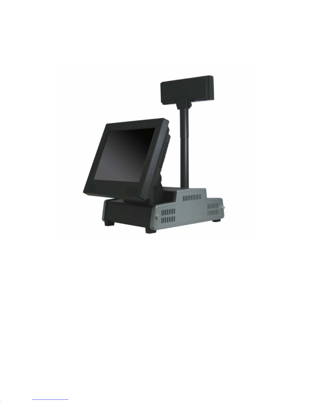
1/68 Version 1.1
UUsseerr M
Maannuuaall
PPOOSS 8877 SSeerriieess
*POS87-2EB-478
*POS87-5EB-478
Jul. 2007
Page 2

2/68 Version 1.1
Copyright Notice
The information in this document is subject to change without prior notice in order to
improve reliability, design and function and does not represent a commitment on the
part of the manufacturer .
In no event will the manufacturer be liable for direct, indirect, special, incidental, or
consequential damages arising out of the use or inability to use the product or
documentation, even if advised of the possibility of such damages.
This document contains proprietary information protected by copyright. All rights are
reserved. No part of this manual may be reproduced by any mechanical, electronic, or
other means in any form without prior written permission of the manufacturer.
Trademarks
Intel is a registered trademark of Intel Corporation. AMI is registered trademarks of
AMI SOFTWARE INTERNATION, INC. Other product names mentioned herein are
used for identification purposes only and may be trademarks and/or registered
trademarks of their respective companies.
Page 3

3/68 Version 1.1
Contents
Chapter 1 – Introduction............................................................................................... 5
1.1 System Overview .............................................................................................. 5
1.1.1 Front View.............................................................................................. 5
1.1.2 Side View................................................................................................ 5
1.1.3 Rear View ............................................................................................... 6
1.1.4 Top View................................................................................................. 6
1.1.5 Bottom View........................................................................................... 6
1.2 Specification...................................................................................................... 7
Chapter 2 – Packing List...............................................................................................11
Chapter 3 – Getting Started......................................................................................... 16
3.1 System setup.................................................................................................... 16
3.2 Hardware Installation.................................................................................... 17
3.2.1 CPU Installation .................................................................................. 17
3.2.2 Memory Installation............................................................................ 18
3.2.3 HDD Installation.................................................................................. 19
3.2.4 CF Card Installation............................................................................ 20
3.2.5 OS Installation..................................................................................... 20
3.3 Software Installation...................................................................................... 21
3.3.1 Intel Chipset Driver............................................................................. 21
3.3.2 Graphic Driver..................................................................................... 22
3.3.3 Touch Panel Driver.............................................................................. 24
3.3.4 Lan Driver............................................................................................ 26
3.3.5 Audio Driver......................................................................................... 27
3.4 Optional Items Installation............................................................................ 29
3.4.1 MSR / RFID ......................................................................................... 29
3.4.2 MSR / Smart Card............................................................................... 32
3.4.3 MSR / iButton...................................................................................... 39
3.4.4 CD-ROM.............................................................................................. 42
3.4.5 Pole Display-VFD ................................................................................ 44
3.4.6 2nd Display ............................................................................................ 50
3.4.7 Mini PCI Wireless LAN...................................................................... 55
Chapter 4 – BIOS setup............................................................................................ 60
4.1 P4 M/B............................................................................................................ 60
4.1.1 Starting Setup................................................................................... 60
4.1.2 Resolution setup.............................................................................. 61
Chapter 5 – M/B Information................................................................................... 64
5.1 M/B Jumper Setting.................................................................................... 64
5.2 COM & RJ-11 Jumper Settings................................................................ 65
5.3 Cash Drawer Introduction......................................................................... 66
Chapter 6 – Reversion History............................................................................... 68
Page 4

4/68 Version 1.1
Introduction
Chapter 1
CHAPTER
Page 5
5/68 Version 1.1
Chapter 1 – Introduction
1.1 System Overview
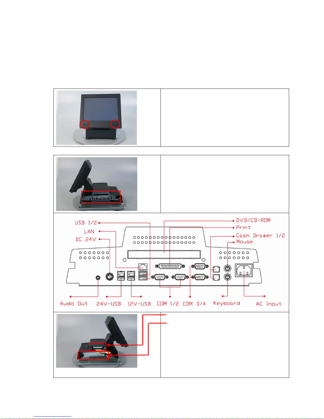
1.1.1 Front View
2 Watt Speakers x 2 .
1.1.2 Side View
I/O Panel (Please see detail description on
Chapter 1.2 Specifications) .
HDD Driver Bay .
Power Supply .
Page 6
6/68 Version 1.1
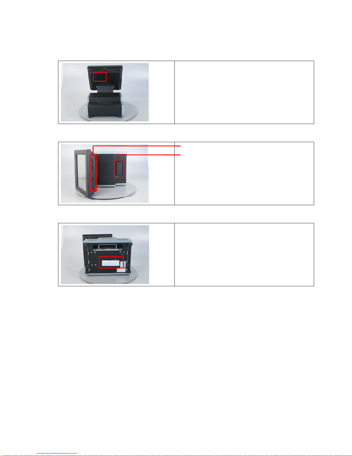
1.1.3 Rear View
Thermal Vents of CPU .
1.1.4 Top View
Thermal Vents of System .
Option for Other Accessories (Pole display or
2nd display) .
1.1.5 Bottom View
Jumper Setting .
Page 7
7/68 Version 1.1
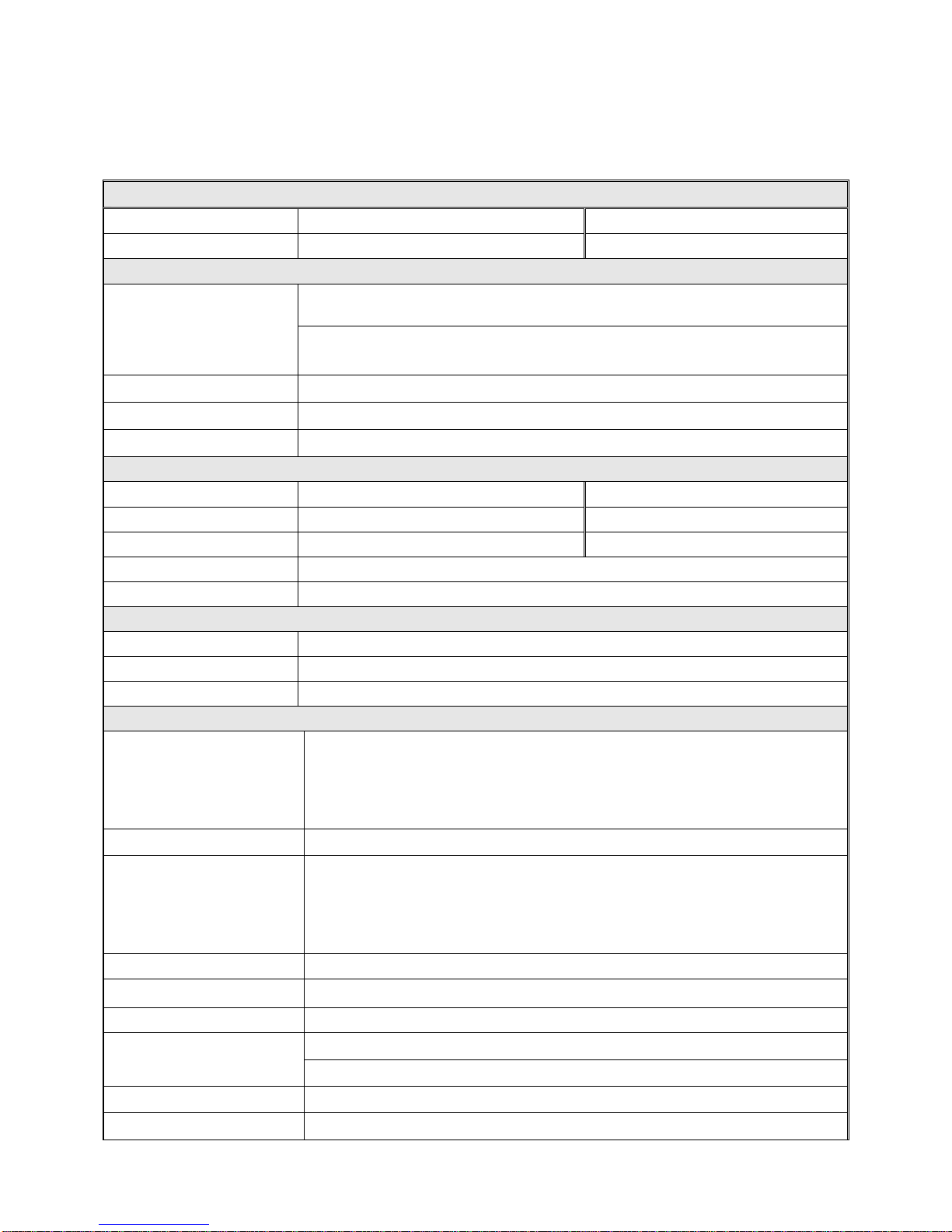
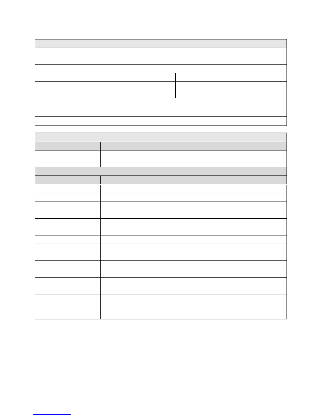
1.2 Specification
System
Model
SolidPOS 872 SolidPOS 875
Intel® Pentium® IV
POS87-2B-478 POS87-5B-478
Main Board
Support Socket 478 Intel® Pentium® IV/ Celeron®, FSB up to 400MHz
CPU
Recommend: Intel® Mobile Celeron® 1.2 GHz or Intel® Celeron® 2.0 GHz or
Intel® Pentium® IV 2.0GHz
Core Logic
Intel® Pentium® IV: Intel® 852GM + ICH4
System Memory
DIMM, DDR266/333, 128MB up to 1GB
OS Support
Win XP / XPe, Linux, WEPOS, WinCE
Display
TFT LCD Size
12.1” 15”
Brightness
200nits 350nits
Resolution
800x600 1024x768
T ouch Screen
7-wire Fujitsu Resistive Type
Tilt Angle 0° to 90°
Storage Device
HDD
1 x IDE , 3.5" HDD
Compact Flash
1 x Slot Compact Flash Type II
CD-ROM
1x Internal, IDE, Slim T y pe, CD-ROM / Combo (CD-RW, DVD-R)
I/O Ports
Serial
6 x RS-232
COM 1/ 2/ 3/ 4: DB-9, RS-232, Pin1 w/ DCD or 5V or 12V Selectable, Pin 9 w/ RI
or 5V or 12V Selectable
COM 5/ 6: Internal for MSR and Touch Panel
Parallel
1 x ECP/EPP/SPP
USB
2 x USB2.0,
1 x USB2.0 w/ 12V
1 x USB2.0 w/ 24V
2 x Internal USB2.0 (On board pin header)
PS/2 Mouse
1 x 6-pin mini DIN
PS/2 Keyboard
1 x 6-pin mini DIN
LAN
1 x RJ-45, 10/100 Base-T
1x Audio Jack Out
Audio
AC’97 2.0 Compliant, 2W speaker * 2
Cash Drawer
2 x RJ-1 1 (Power Pin 12/24V Selectable)
Expansion
1 x Mini PCI
Page 8
8/68 Version 1.1
Others
Power Input
220W ATX with 100 - 240V AC input @ 50 - 60 Hz
Color
Black
EMC& Safety Compliance
FCC / CE
Weight (Kgs)
12 12.5
Dimension L x W x H
(mm)
361 x 313 x 347 361 x 370 x 384
Operating Temperature
0°C ~ 40°C
Storage Temperature
-20°C ~ 60°C
Storage Humidity
20% - 85% RH, non-condensing
A10400623RH 2nd Display: 12.1” w/ Touch
A10400624RH 2nd Display: 15” w/ Touch
A10400188RH 2nd Display: 12.1” w/o Touch
A10400189RH 2nd Display: 15” w/o Touch
A10400622RH Customer Display: LCD Pole Display
A10400335RH Customer Display: VFD Pole Display
A10400010RH MSR: 2 Tracks, PS/2 Type
A10400009RH MSR: 3 Tracks, PS/2 Type
A10400023RH MSR: 2 Tracks, RS-232 Type
A10400024RH MSR: 3 Tracks, RS-232 Type
A10400019RH iButton: PS/2 Type
A10400121RH
MSR: 2 Tracks, PS/2 Type
iButton: PS/2 Type
A10400120RH
MSR: 3 Tracks, PS/2 Type
iButton: PS/2 Type
A10400302RH Smart Card: USB Type
Main Unit Ordering Information
Part No. Description
POS87-2B-478
SolidPOS 872 w/ 12.1” TFT LCD, Intel® Pentium® IV Socket 478 CPU
POS87-5B-478
SolidPOS 875 w/ 15” TFT LCD, Intel® Pentium® IV Socket 478 CPU
Optional Accessories Ordering Information
Part No. Description
Page 9

9/68 Version 1.1
A10400306RH
MSR: 2 Tracks, PS/2 Type
Smart Card: USB Type
A10400305RH
MSR: 3 Tracks, PS/2 Type
Smart Card: USB Type
A10400304RH
MSR: 2 Tracks, RS-232 Type
Smart Card: USB Type
A10400104RH
MSR: 3 Tracks, RS-232 Type
Smart Card: USB Type
A10400005RH RFID: RS-232 Type
A10400266RH WIRELESS LAN 802.11 b/g Mini PCI Module w/ Antenna
20900001RH OS: Win XP Professional (English Version)
20900002RH OS: WEPOS (English Version)
20600003RH Compact Flash: 512MB
20600005RH Compact Flash: 1GB
20300003RH DDR333, 512MB, 184Pin, SDRAM
20300002RH DDR333, 256MB, 184Pin, SDRAM
20200014RH HDD: 3.5-inch, 40GB, Ultra ATA/100, 5400RPM
Page 10

10/68 Version 1.1
Packing List
Chapter 2
CHAPTER
Page 11
11/68 Version 1.1
Chapter 2 – Packing List
The unit comes securely packaged in a shipping carton. Please contact your dealer if you find that anything is
missing or damaged after examining the contents. The shipping carton should contain the following standard
items :
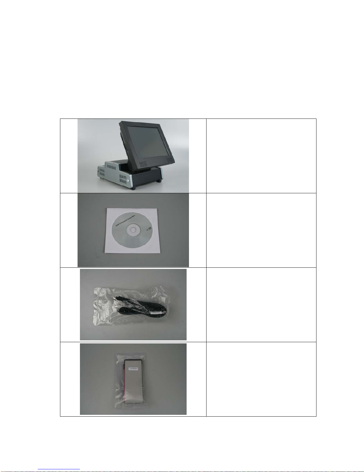
2.1 Standard Items
Main Unit .
Driver CD (Include manual) .
Printer power extension cable (24V ) .
IDE extension cable .
Page 12
12/68 Version 1.1
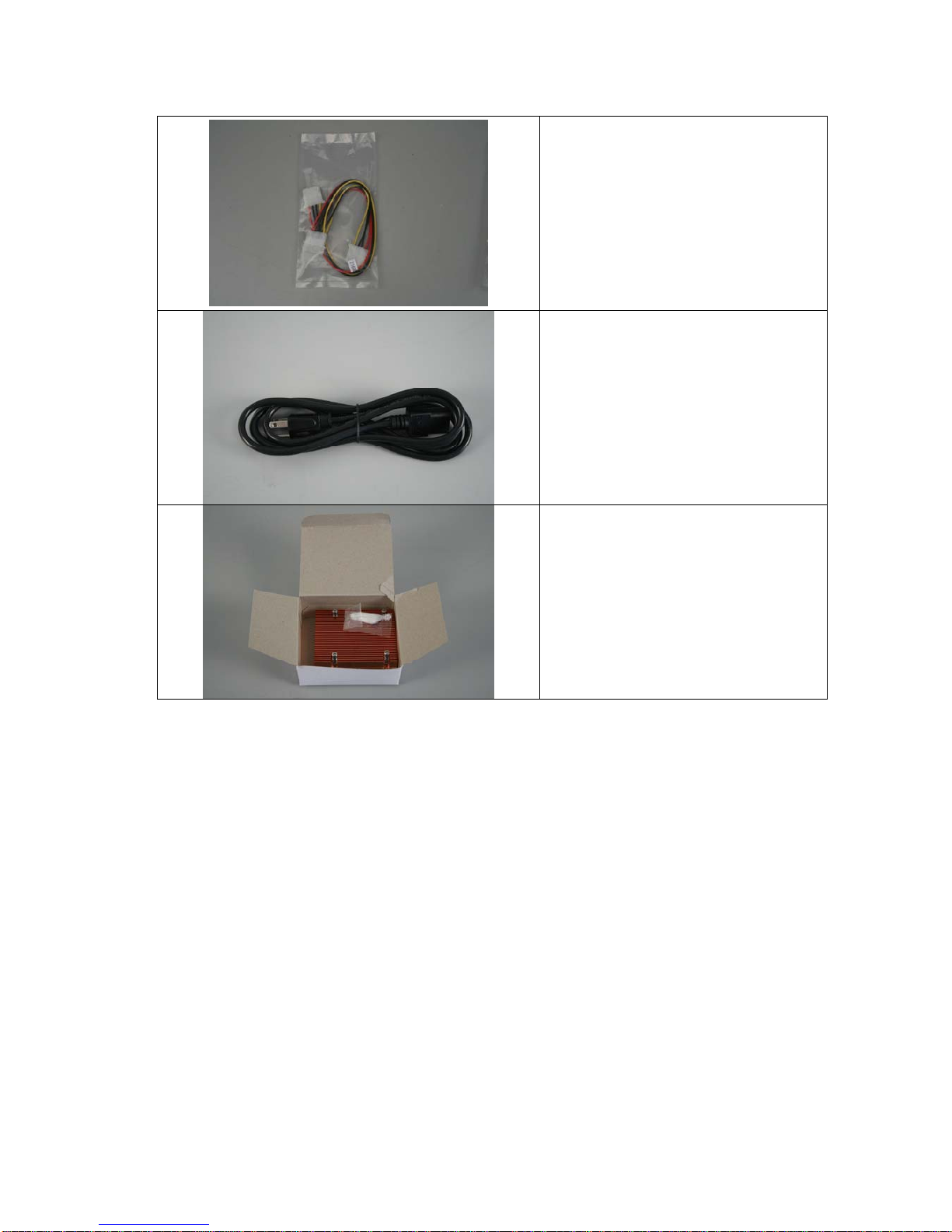
HDD & CD-ROM power extension
cable .
Power Cord (The picture varies from
the area you locate) .
CPU Heatsink .
Page 13
13/68 Version 1.1
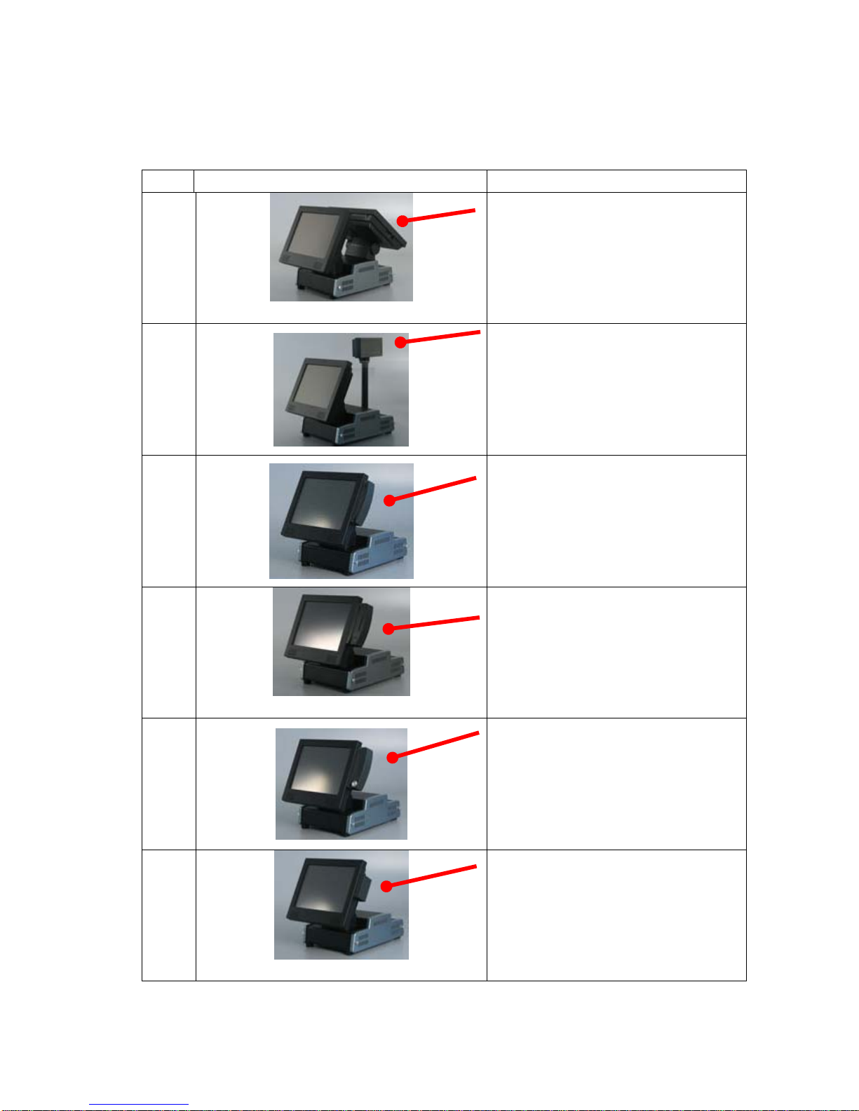
2.2 Optional Items
Item Photo Description
1
2nd Display
2
Customer Display (VFD, LCD)
3
MSR
(1+2 Track PS/2 or RS-232, 1+2+3
Track PS/2 or RS-232)
4
2-in-1 Card Reader (MSR, Smart
Card)
5
MSR and iButton
6
RFID
Page 14
14/68 Version 1.1
Item Photo Description
7
WLAN:IEEE 802.11g
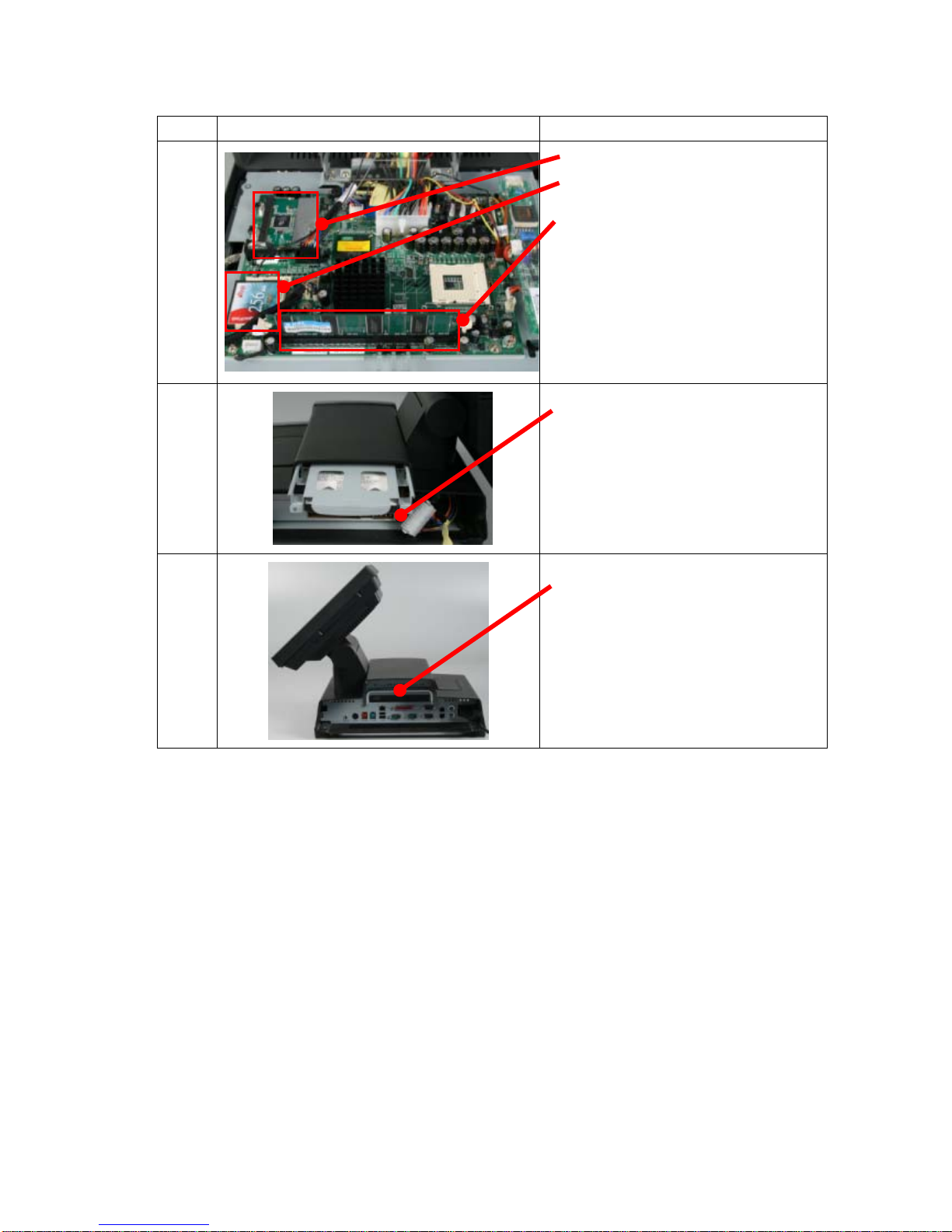
CF
Memory: DIMM, DDR266/333
8
HDD: 3.5”
9
Slim type CD-ROM
Page 15

15/68 Version 1.1
Getting Started
Chapter 3
CHAPTER
Page 16
16/68 Version 1.1
Chapter 3 – Getting Started
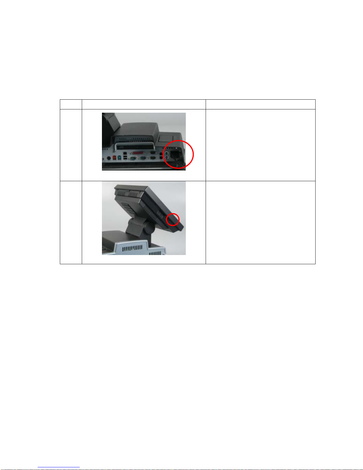
3.1 System setup
Item Photo Description
1
Plug-in power cord and connect with
AC power
2
Push “Start Button”
Page 17
17/68 Version 1.1
3.2 Hardware Installation
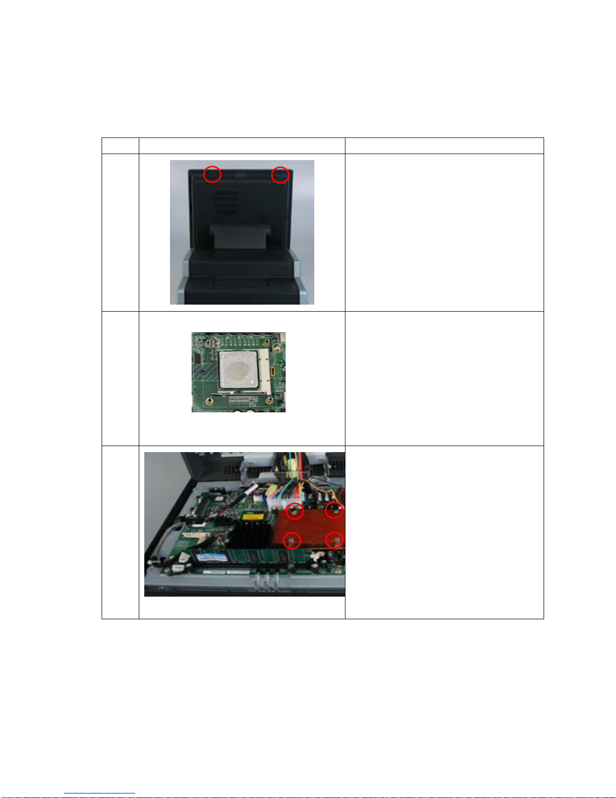
3.2.1 CPU Installation
Item Photo Description
1
Remove 2 screws
2
Install CPU and apply the thermal
adhesive glue
3
Install thermal module
Fasten 4 screws
Page 18
18/68 Version 1.1
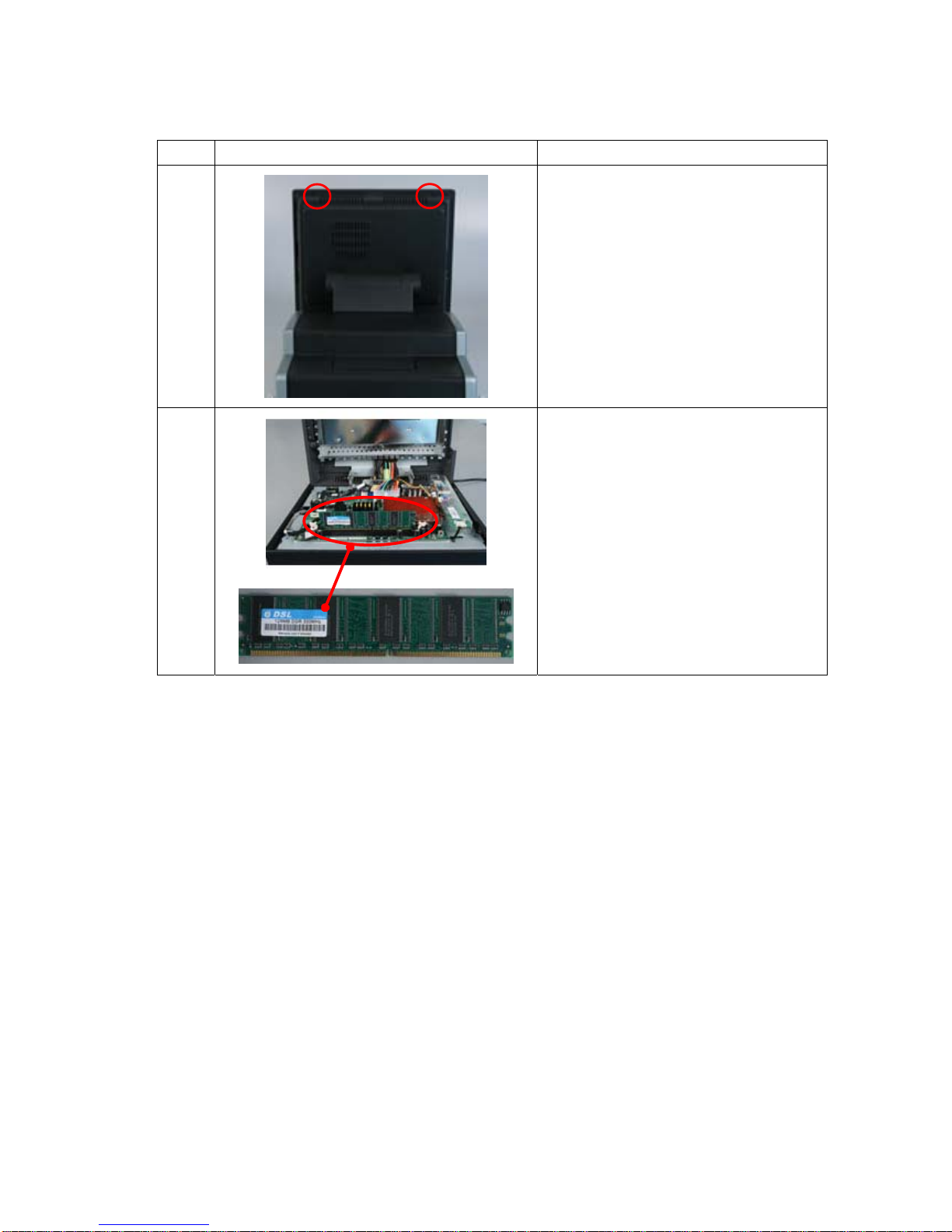
3.2.2 Memory Installation
Item Photo Description
1
Remove 2 screws
2
Install Memory module
Page 19
19/68 Version 1.1
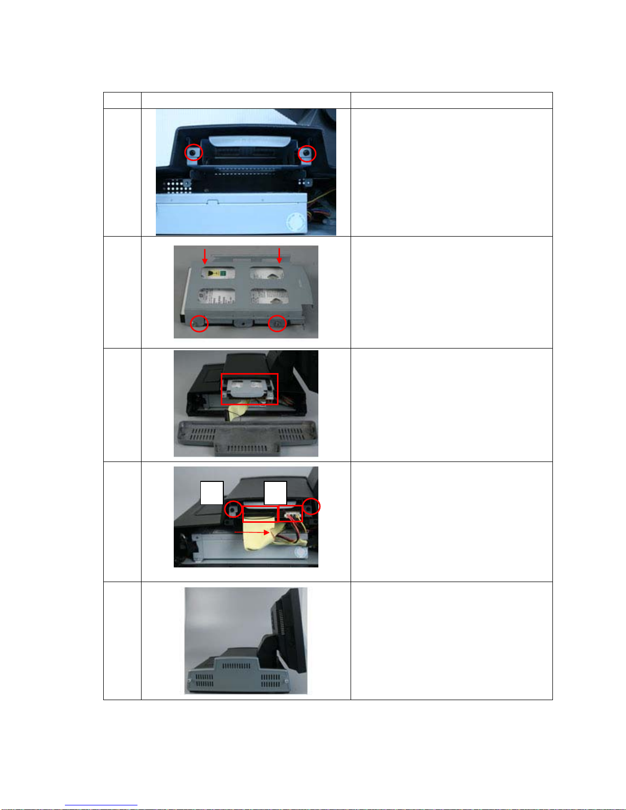
3.2.3 HDD Installation
Item Photo Description
1
Remove 2 screws from HDD case and
pull out HDD case.
2
1. Install HDD in the metal case.
2. Fasten 4 screws
3
Slide the HDD into the POS system
4
1. Fasten 2 screws on the HDD cover
2. Plug in IDE and power cable
Note: Ensure the red line of IDE cable is at right
hand side
5
Put on the cover and fasten 2 screws
1 2
Page 20
20/68 Version 1.1
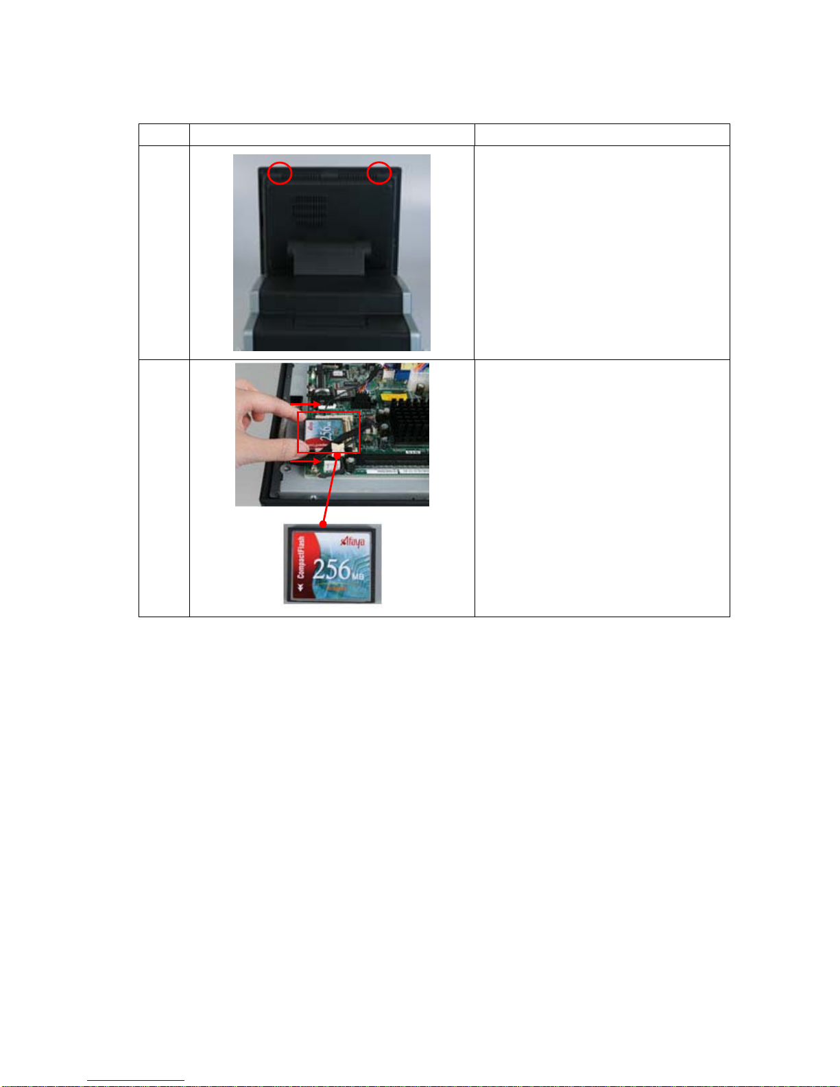
3.2.4 CF Card Installation
Item Photo Description
1
Remove 2 screws
2
Push CF into CF slot
3.2.5 OS Installation
a. Please prepare a USB CD-ROM .
b. Plug a USB CD-ROM into the USB port of POS system .
c. Turn on the system and enter CMOS configuration page
d. Set the boot up device as USB CD-ROM
e. Reboot the system
f. Install OS step by step
Page 21
21/68 Version 1.1
3.3 Software Installation
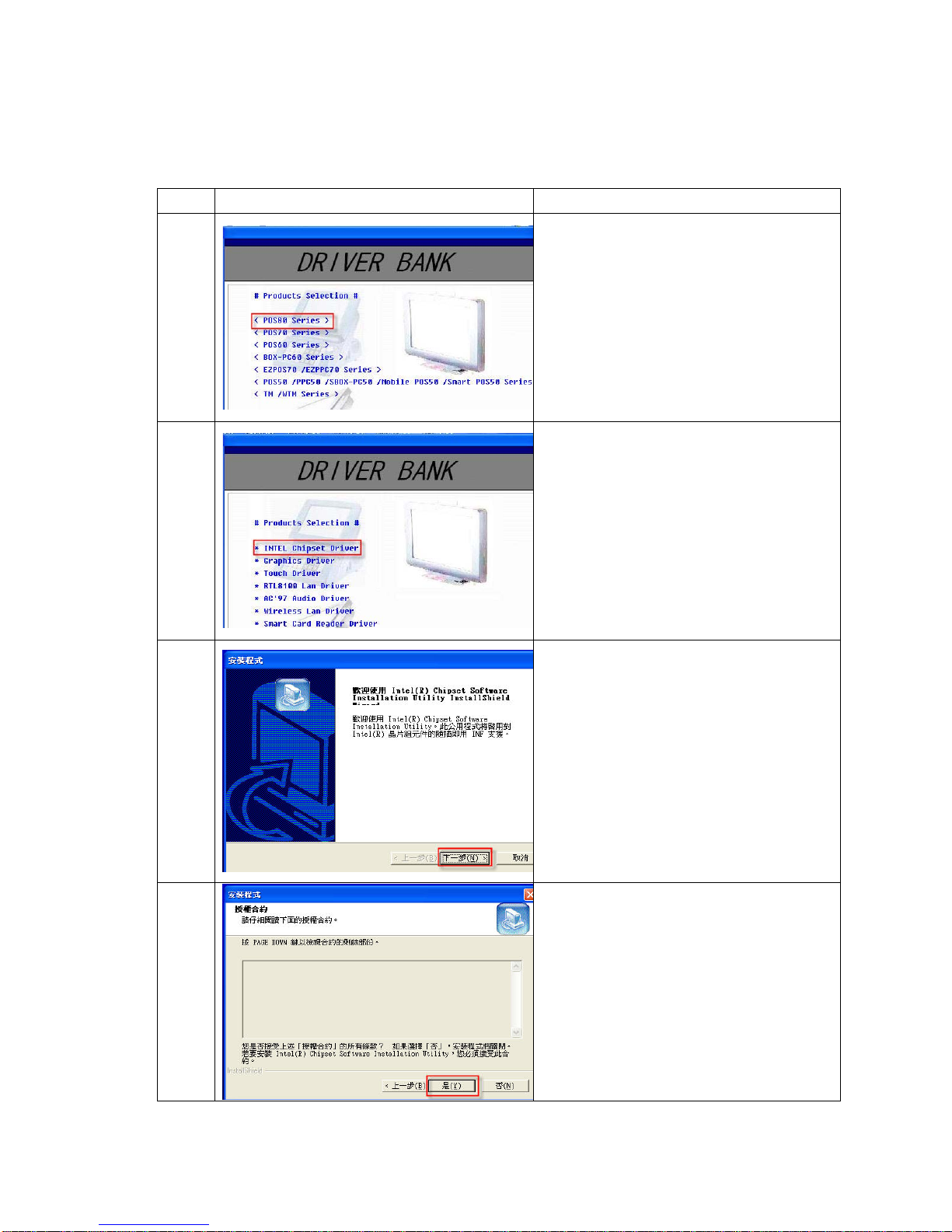
3.3.1 Intel Chipset Driver
Item Photo Description
1 Insert driver CD and select POS 8 series
2 Select “Intel Chipset Driver”
3 Click “Next”
4 Click “Yes”
Page 22
22/68 Version 1.1
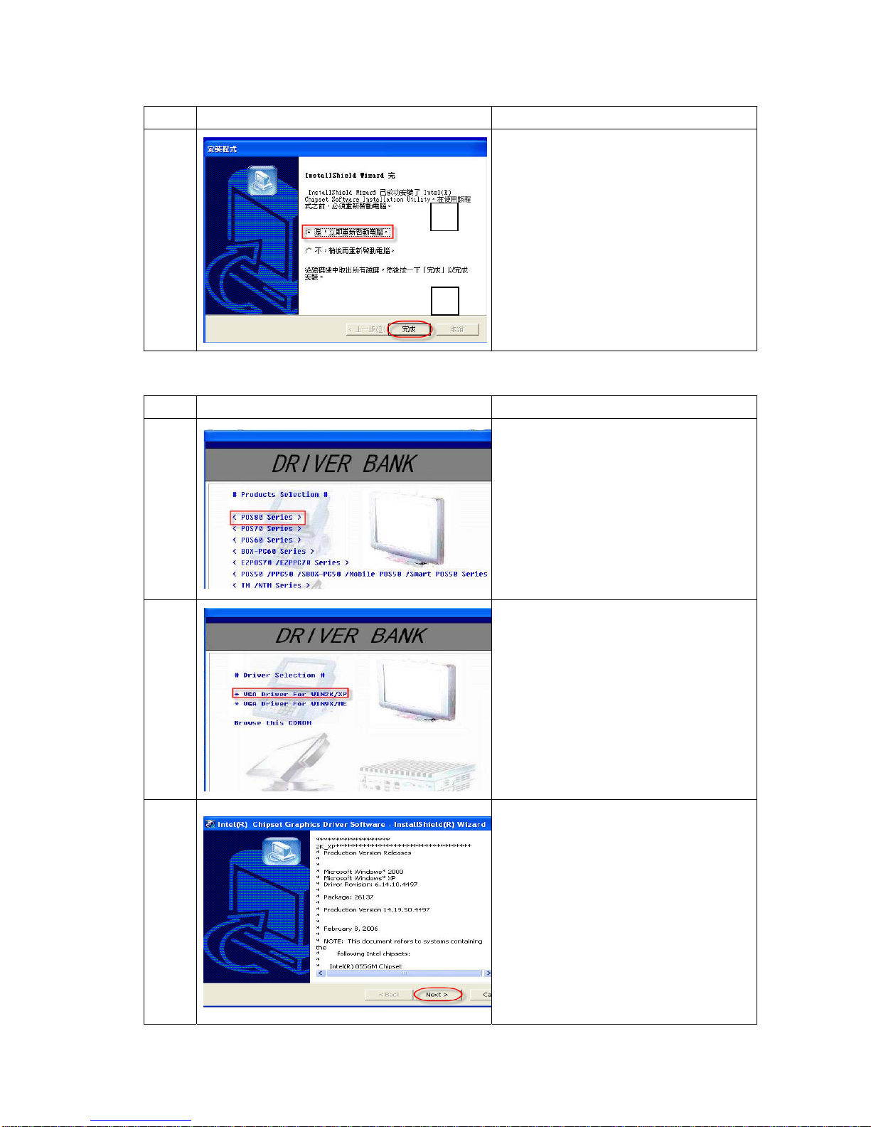
Item Photo Description
5
1. Click “Yes, Restart my computer
now”
2. Click “Complete”
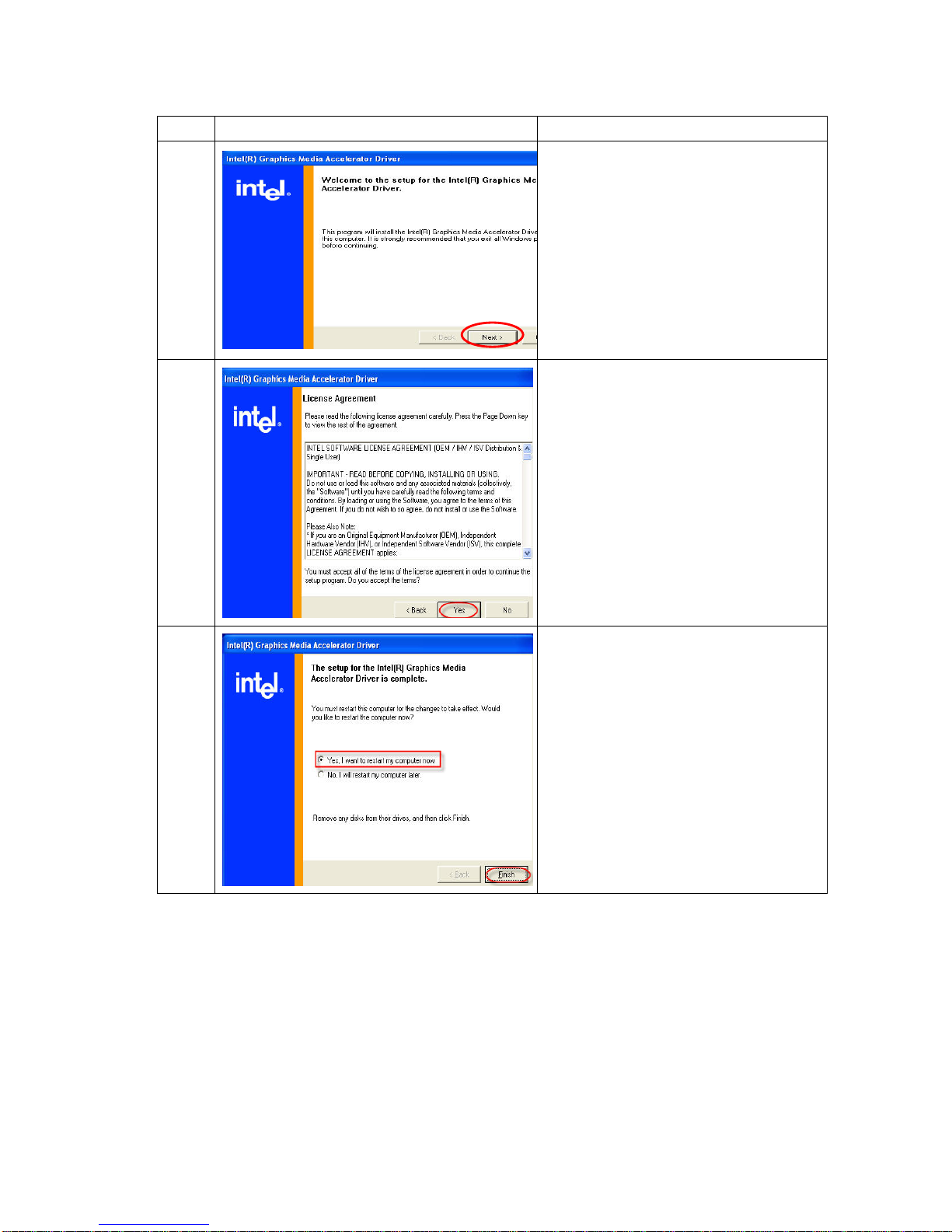
3.3.2 Graphic Driver
Item Photo Description
1
Insert driver CD and select POS 8
series
2
1. Base on OS version and select the
VGA driver( Ex. WinXP)
3 1. Click “Next”
1
2
Page 23
23/68 Version 1.1
Item Photo Description
4 1. Click “Next”
5 1. Click “Yes”
6
1. Click “Yes, I want to restart my
computer now”
Page 24
24/68 Version 1.1
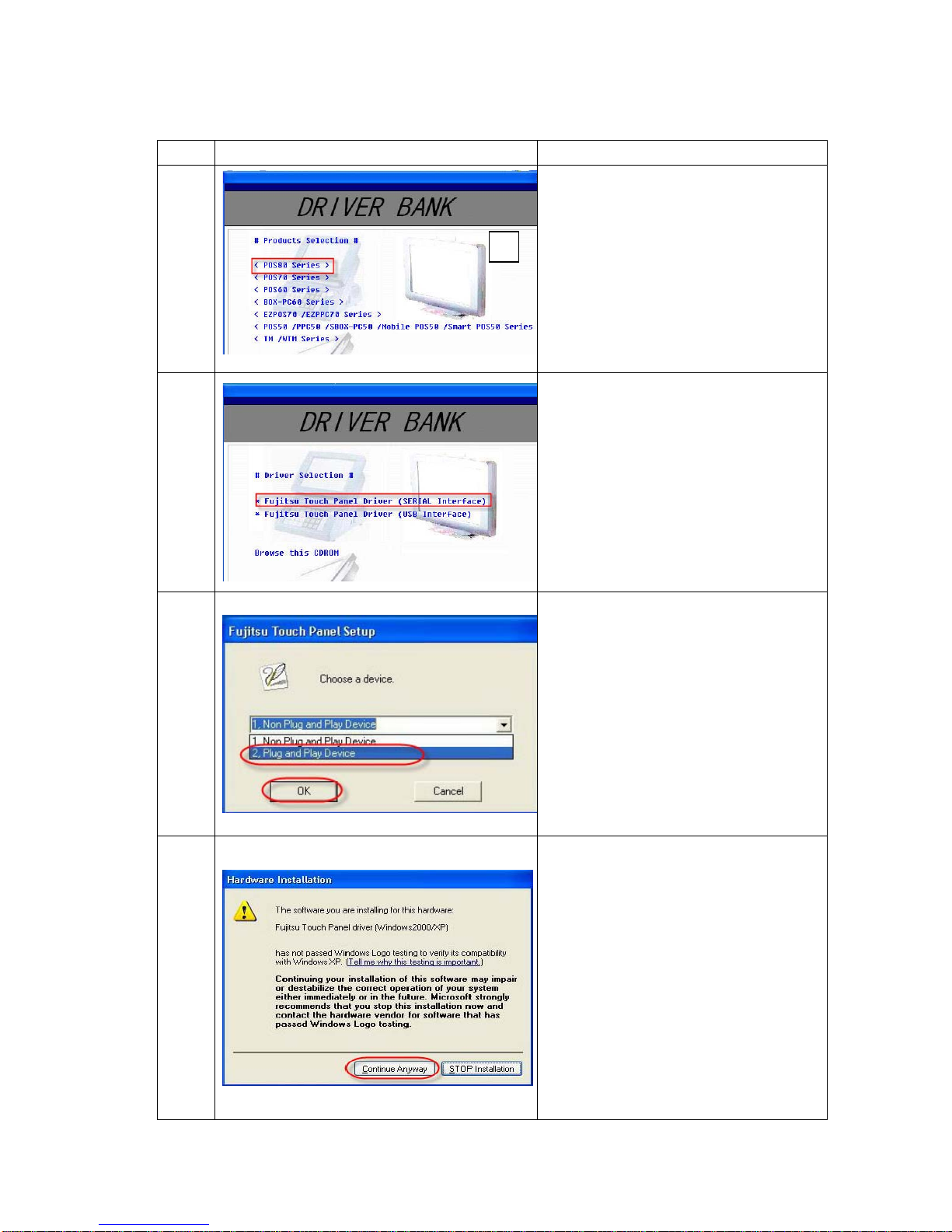
3.3.3 Touch Panel Driver
Item Photo Description
1
1. Insert driver CD and select POS 8
series
2
1. Select “Fujitsu Panel Driver( Serial
Interface)”
3
1. Click “2. Plug and Play Device”
2. Click “OK”
4 Click “Continue Anyway”
1
Page 25
25/68 Version 1.1
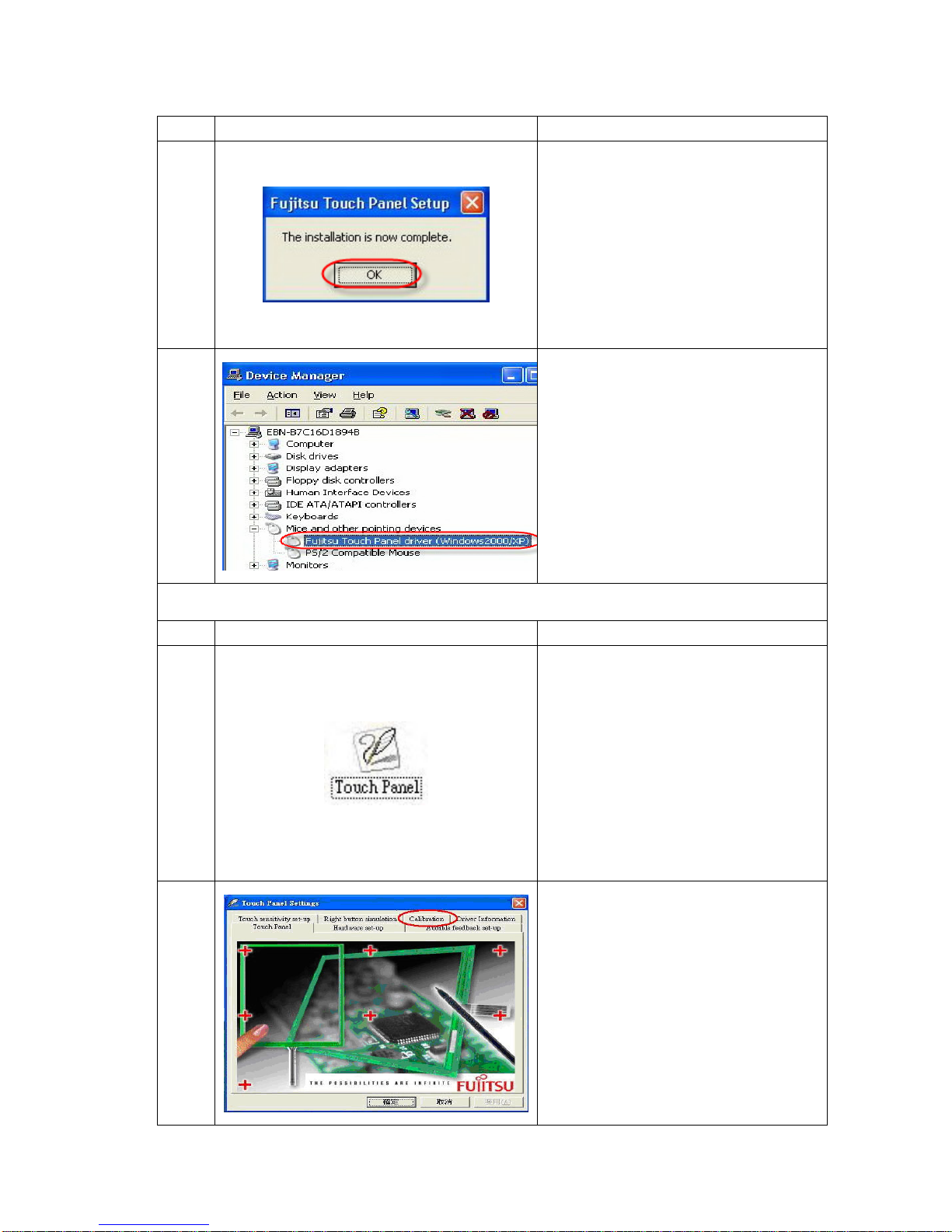
Item Photo Description
5
1. Click “OK”
6
1. Check device manager, the “Fujitsu
Touch Panel Driver…” should be
listed on the screen
Touch Panel Calibration
Item Photo Description
7
Execute “Touch Panel” from Windows
Control Panel
8 Click at “Calibration”
Page 26
26/68 Version 1.1
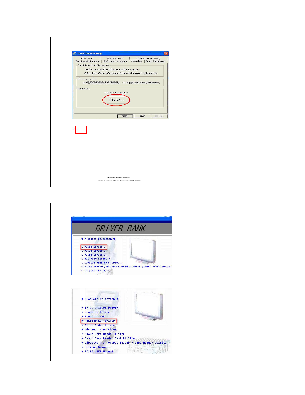
Item Photo Description
9 Click at “Calibrate Now”
10
1. Follow the curser to click on the
screen for calibration
3.3.4 Lan Driver
Item Photo Description
1
1. Insert driver CD and select POS 8
series
2 1. Select “RTL8100 Lan Driver”
Page 27
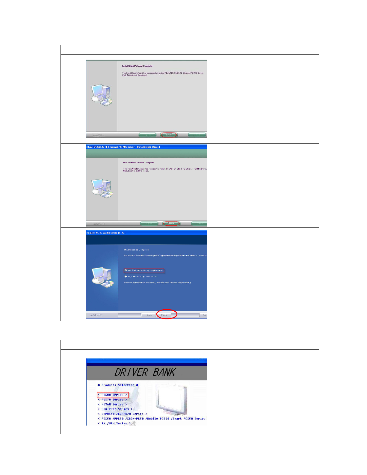
27/68 Version 1.1
Item Photo Description
3 1. Click “Install”
4 1. Click “Finish”
5
1. Click “Yes, I want to restart my
computer now”
2. Click “Finish”
3.3.5 Audio Driver
Item Photo Description
1
1. Insert driver CD and select POS 8
series
Page 28
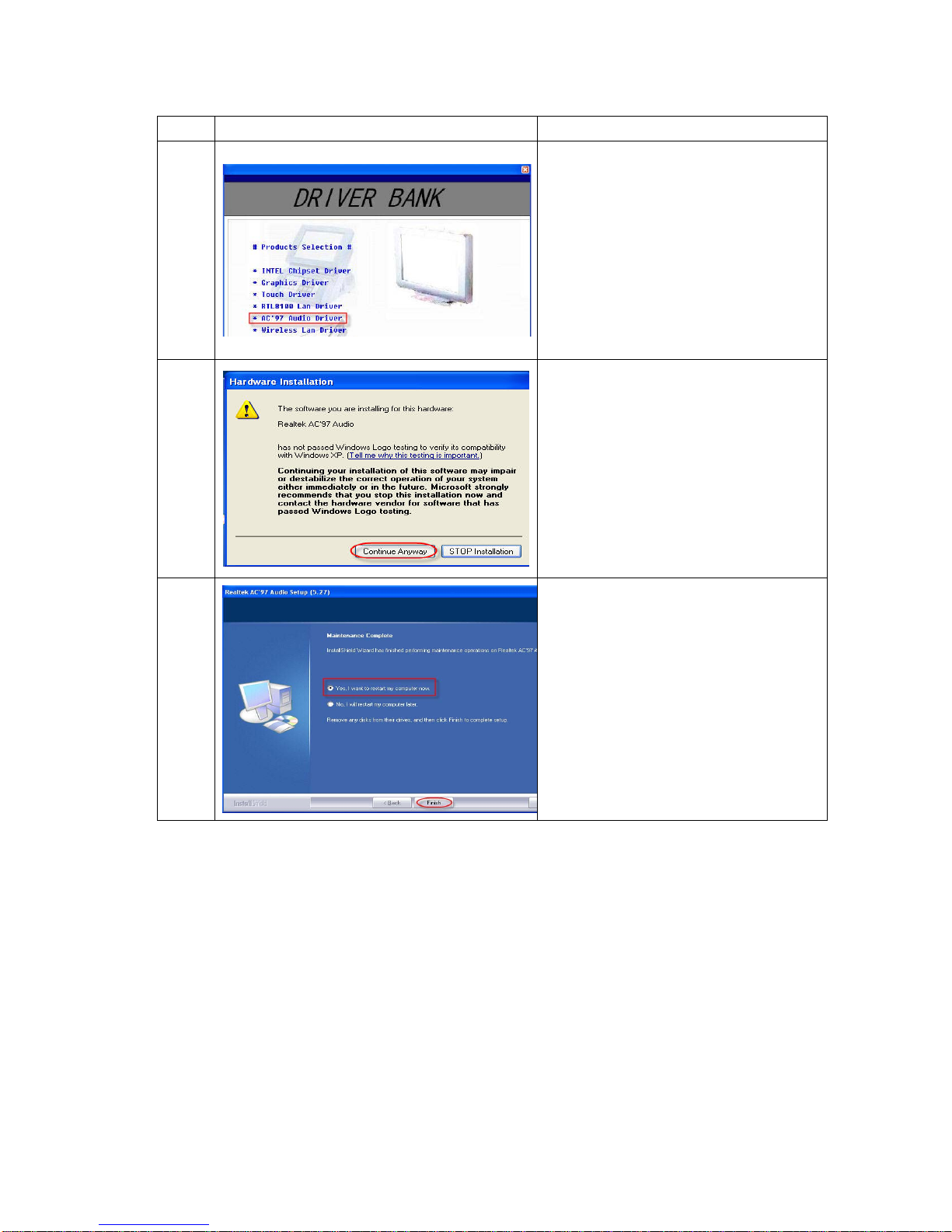
28/68 Version 1.1
Item Photo Description
2 1. Select “AC ’97 Audio Driver”
3 1. Click “Continue Anyway”
4
1. Select “Yes, I want to restart my
computer now”
Page 29
29/68 Version 1.1
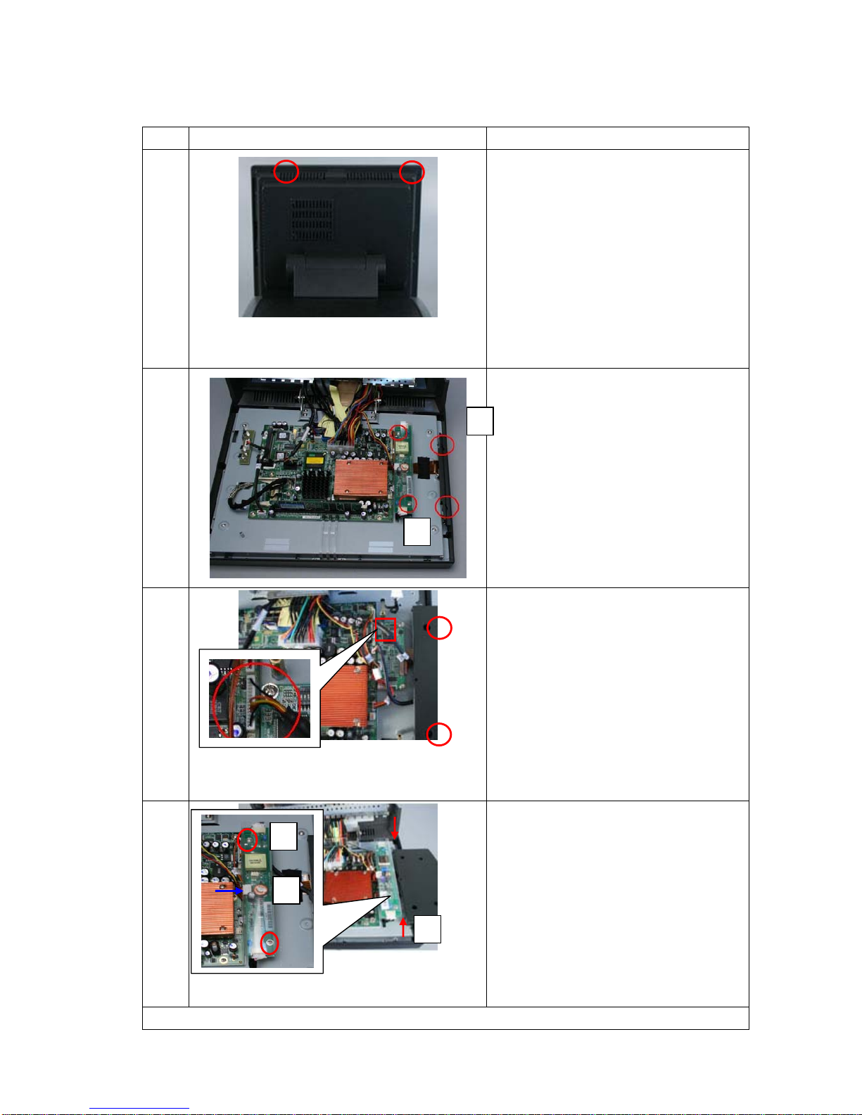
3.4 Optional Items Installation
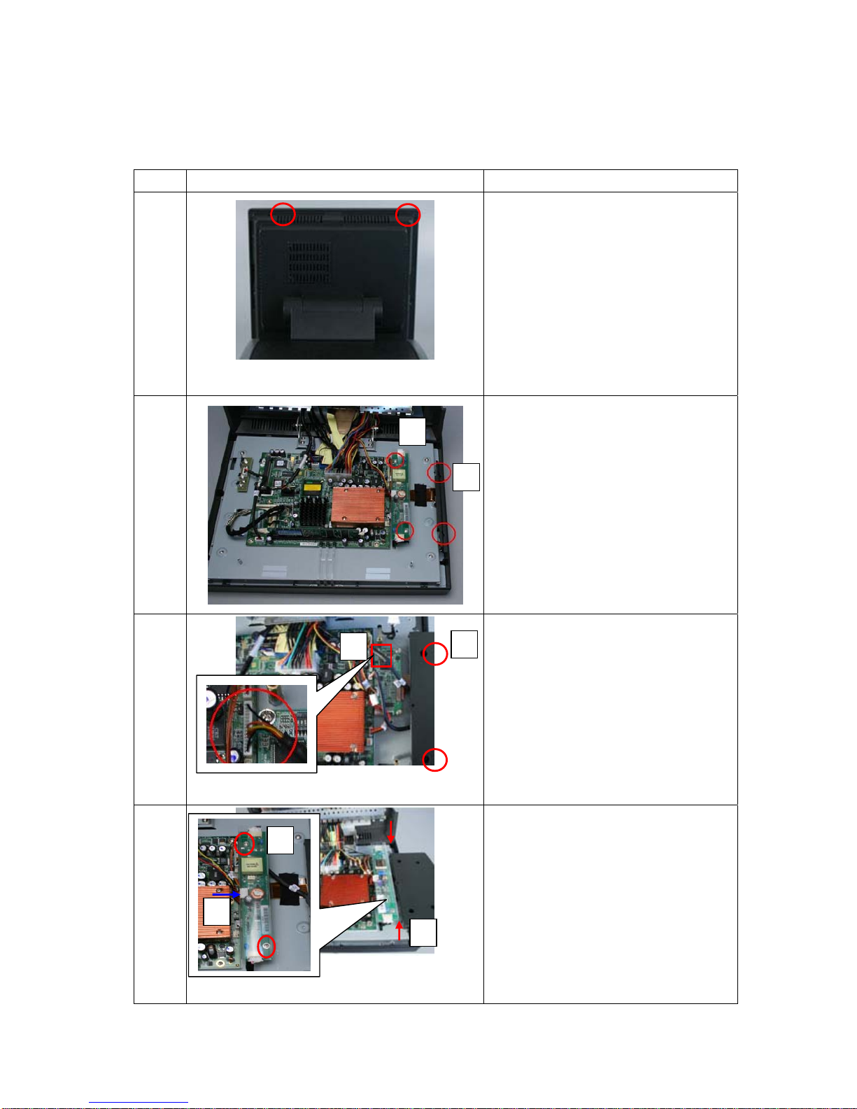
3.4.1 MSR / RFID
Item Photo Description
1
1. Remove 2 screws from system
2
1. Remove plastic cover
2. Remove inverter from system
3
1. Fasten 2 screws to connect MSR
and POS system
2. Plug MSR cable on main
board(CN5)
4
1. Put inverter in the system and
fasten 2 screws
2. Plug LCD cables to inverter
3. Plug cable between main board
and inverter
4. Close front cover and fasten 2
screws
2
3
1
1
2
1
2
Page 30
30/68 Version 1.1
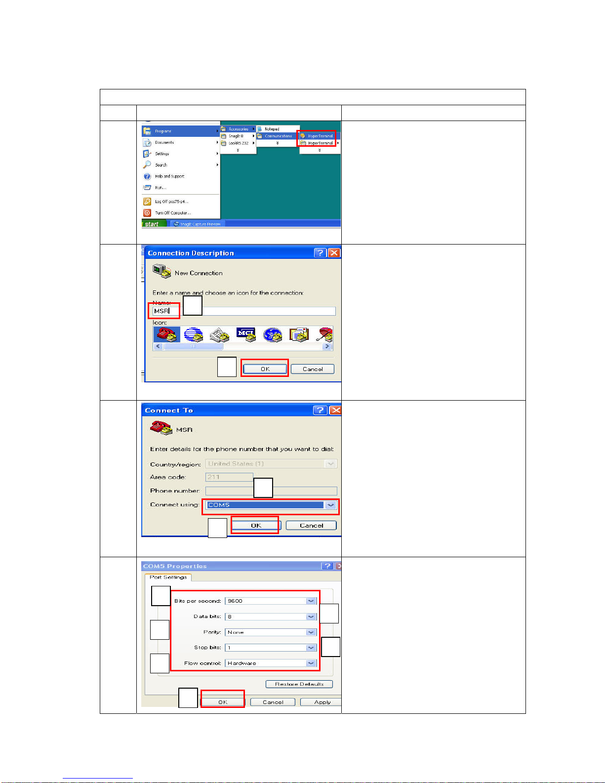
MSR Verification (Only for RS-232 interface)
Item Photo Description
5
1. Click
“Start”Æ”Program”Æ”Accessories”
Æ “Communications”Æ “Hyper
Terminal”
6
1. Name for the MSR Module(Ex.
MSR)
2. Click “OK”
7
1. Set Connect using as “COM5”
2. Click “OK”
8
1. Set Bits per second: 9600
2. Data bits: 8
3. Parity: None
4. stop bits: 1
5. Flow control: Hardware
6. Click “OK”
1
2
3
4
5 6
1
2
2
1
Page 31
31/68 Version 1.1
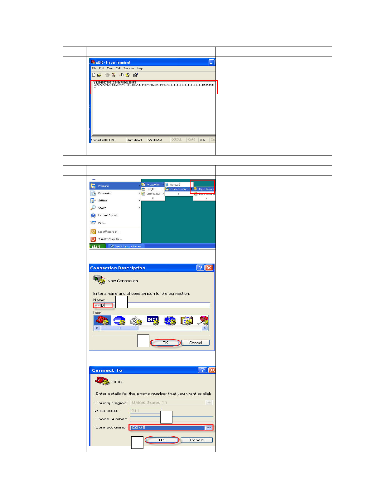
Item Photo Description
9
1. Stripe the MSR card to Reader and
card information will be shown on the
screen
RFID Verification
Item Photo Description
10
1. Click
“Start”Æ”Program”Æ”Accessories”
Æ “Communications”Æ “Hyper
Terminal”
11
1. Name for the RFID Module(Ex.
RFID)
2. Click “OK”
12
3. Set Connect using as “COM5”
4. Click “OK”
1
2
2
1
Page 32
32/68 Version 1.1
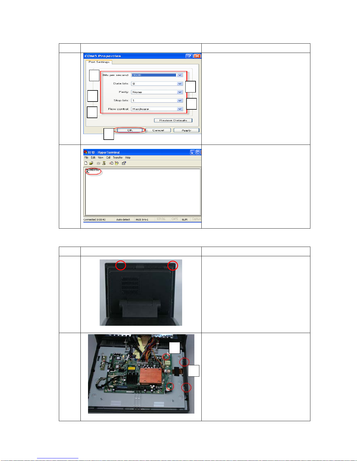
Item Photo Description
13
1. Set Bits per second: 9600
2. Data bits: 8
3. Parity: None
4. Stop bits: 1
5. Flow control: Hardware
6. Click “OK”
14
1. Stripe the RFID card to Reader and
card information will be shown on the
screen
3.4.2 MSR / Smart Card
Item Photo Description
1
Remove 2 screws from system
2
3. Remove plastic cover
4. Remove inverter from system
1
2
Page 33
33/68 Version 1.1
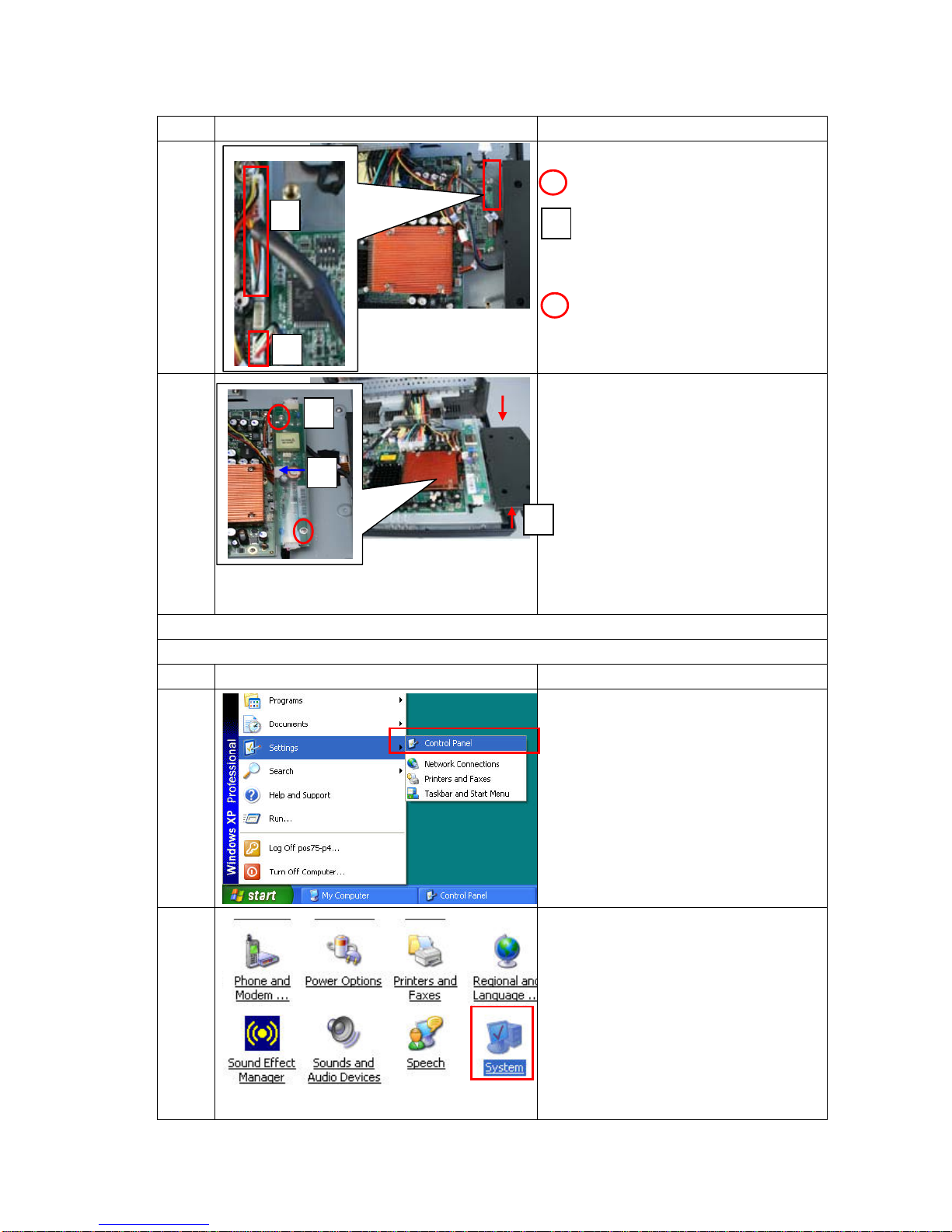
Item Photo Description
3
1. Fasten 2 screws to connect MSR
and POS system
2. Plug MSR cable on main
board(CN5)
3. Plug smart card cable on main
board(USB2)(if smart card is
selected)
4
1. Put inverter in the system and
fasten 2 screws
2. Plug LCD cables to inverter
3. Plug cable between main board
and inverter
4. Close front cover and fasten 2
screws
MSR Verification, please refer to 3.4.1 item 5 to 9
Smart Card Driver Installation
Item Photo Description
5
1. Click “Start”Æ “Setting”Æ
“Control Panel”
6 1. Click System
1
2
3
2
3
1
Page 34
34/68 Version 1.1
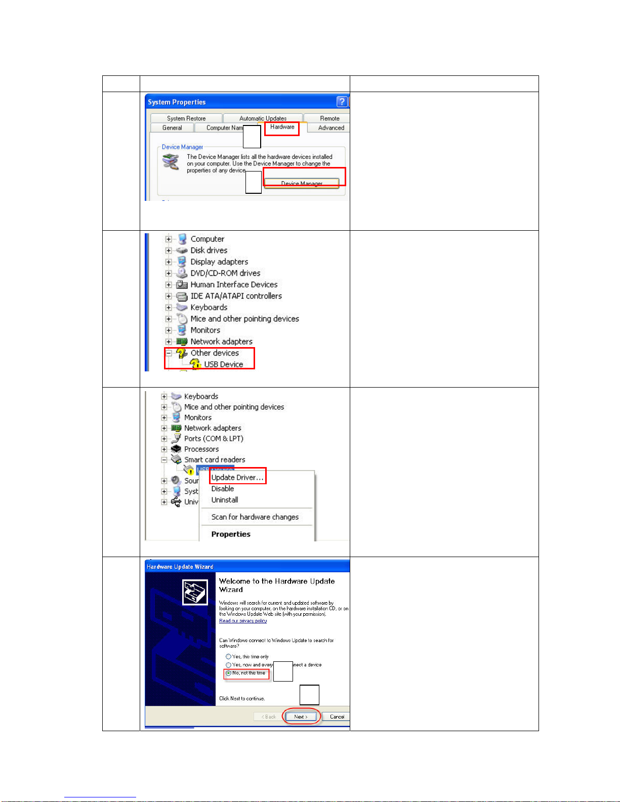
Item Photo Description
7
1. Click “Hardware”
2. Click “Device Manager”
8 1. Right click the mouse
9 1. Click “Update Driver”
10
1. Select “No, not this time”
2. Click “Next”
1
2
1
2
Page 35
35/68 Version 1.1
Item Photo Description
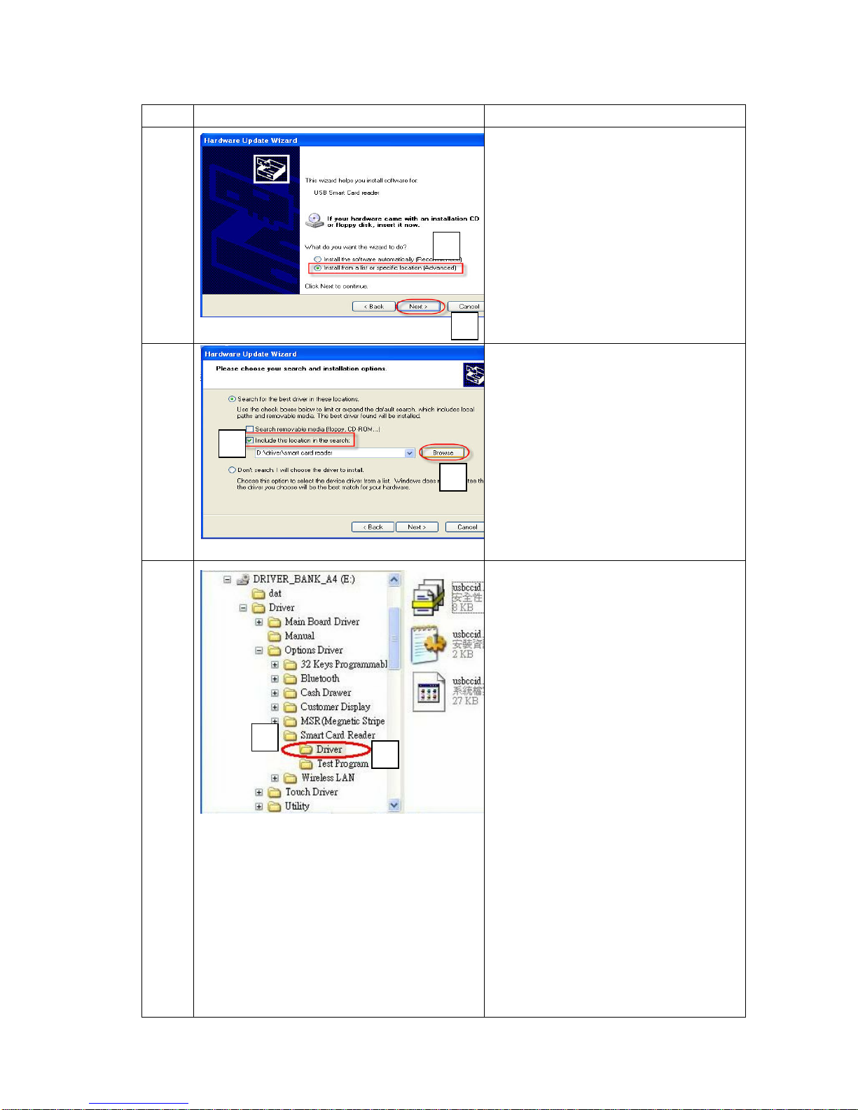
11
1. Select “Install from a list or
specific location (Advanced)”
2. Click “Next”
12
1. Select “Indicate the location in the
network”
2. Click “Browse”
13
1. Select CD-ROM, folder named
“smart card reader”
2. Click “OK”
1
1
2
2
2
1
Page 36
36/68 Version 1.1
Item Photo Description
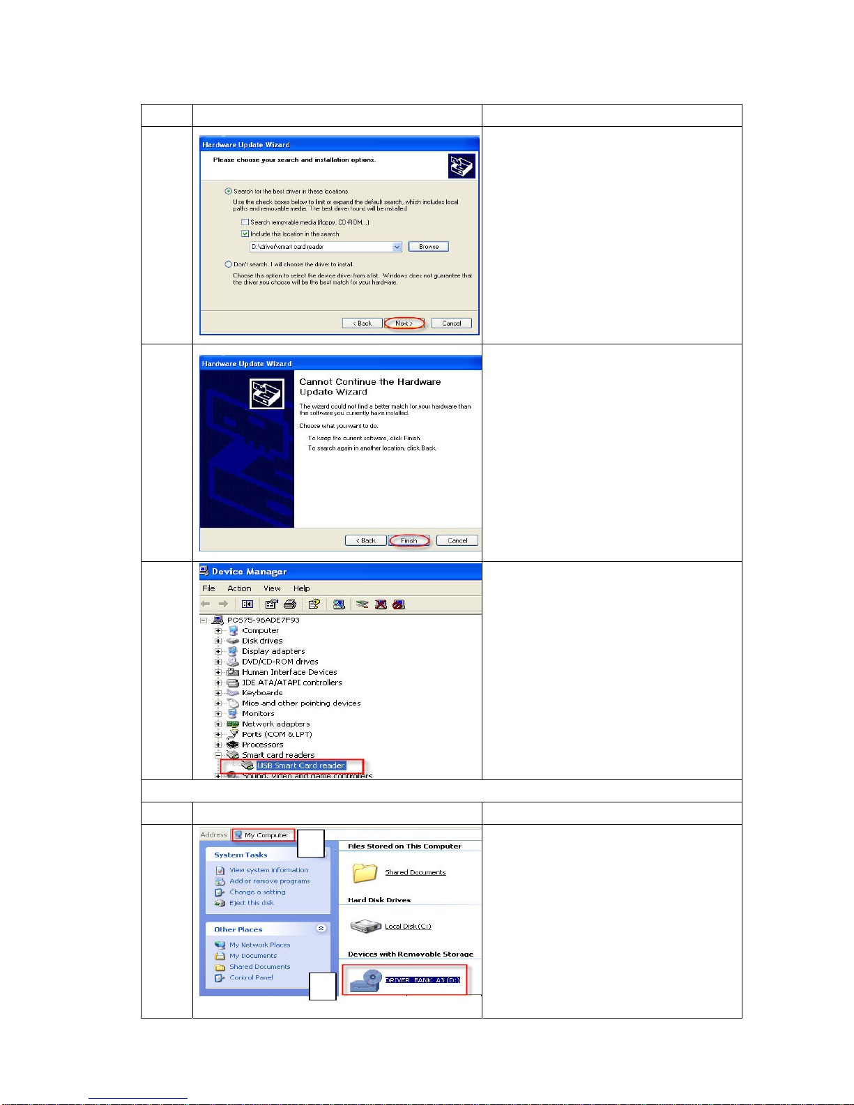
14 1. Click “Next”
15 1. Click “Finish”
16
1. The USB Smart Card reader device
is detected by the system
Smart Card Utility Verification
Item Photo Description
17
1. Click “My Computer”
2. Click “CD-ROM”
1
2
Page 37
37/68 Version 1.1
Item Photo Description
18
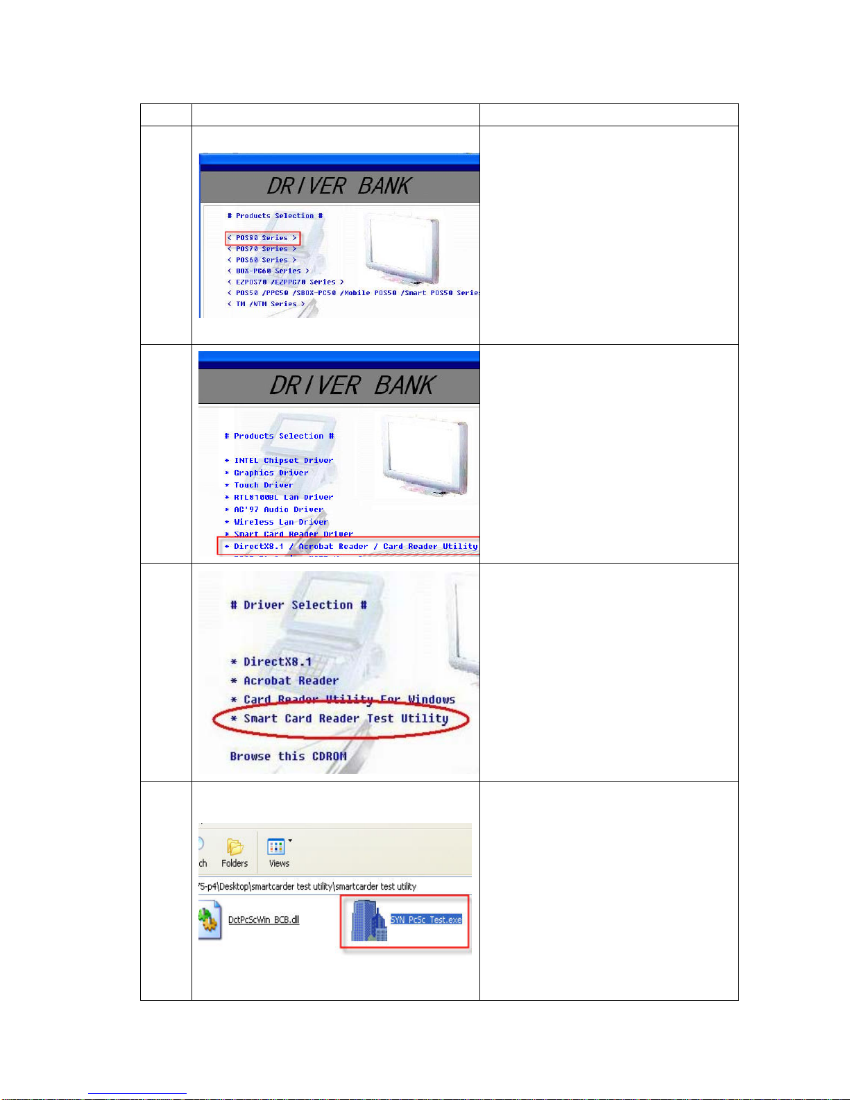
1. Insert driver CD and select POS 8
series
19
1. Select “Directx8.1 / Acrobat
Reader/ Card Reader Utility”
20
1. Select “Smart Card Reader Test
Utility”
21 1. Select “SYN PcSc Test.exe”
Page 38
38/68 Version 1.1
Item Photo Description
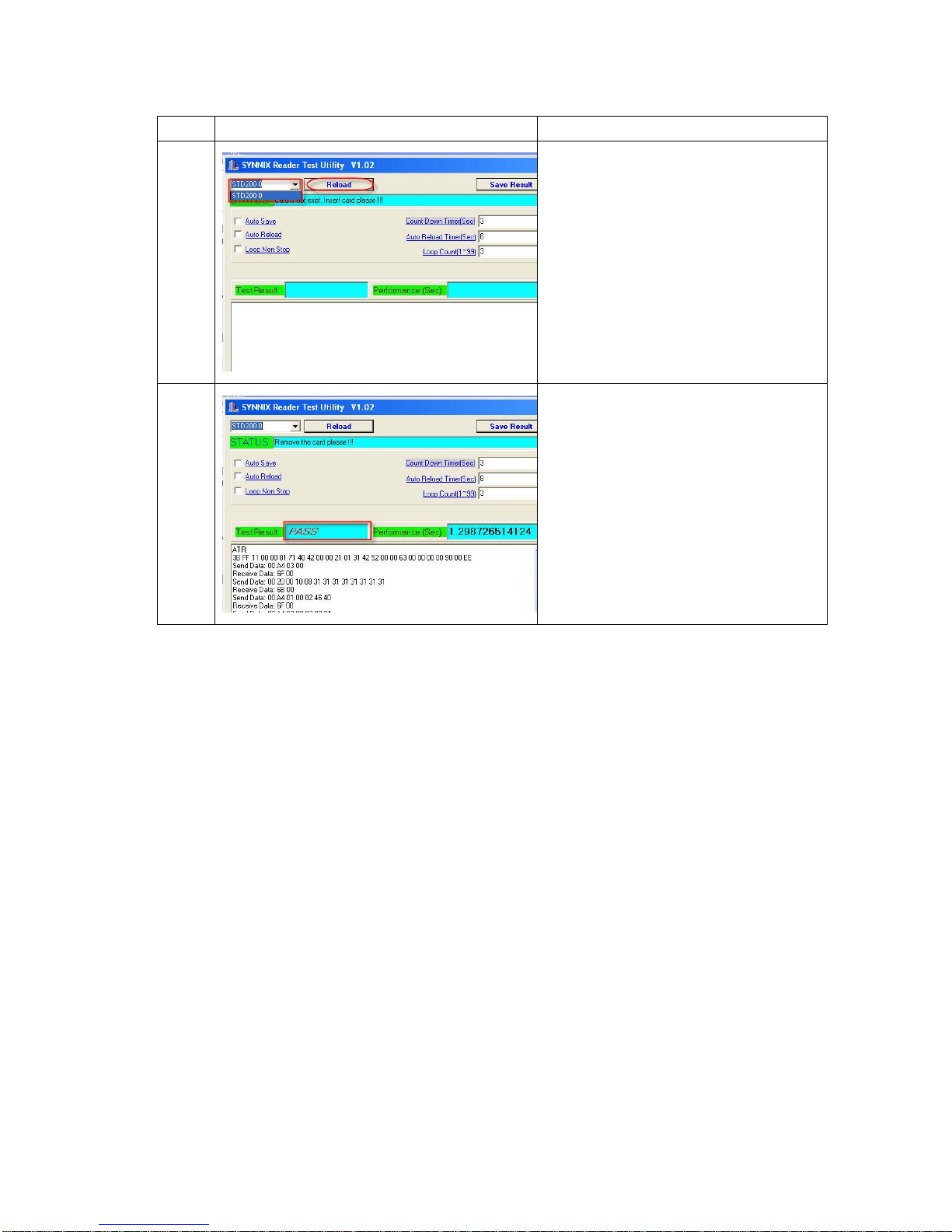
22
1. Select “STD2000”
2. Click “Reload”
23
1. The result will show “PASS” on the
screen
Page 39
39/68 Version 1.1
3.4.3 MSR / iButton
Item Photo Description
1
Remove 2 screws from POS system
2
1. Remove plastic cover
2. Remove inverter from system
3
1. Fasten 2 screws to connect MSR /
iButton and POS system
2. Plug MSR cable on main
board(CN5)
4
1. Put inverter in the system and
fasten 2 screws
2. Plug LCD cables to inverter
3. Plug cable between main board
and inverter
4. Close front cover and fasten 2
screws
MSR Verification (Only for RS-232 interface)
2
3
1
1
2
Page 40
40/68 Version 1.1
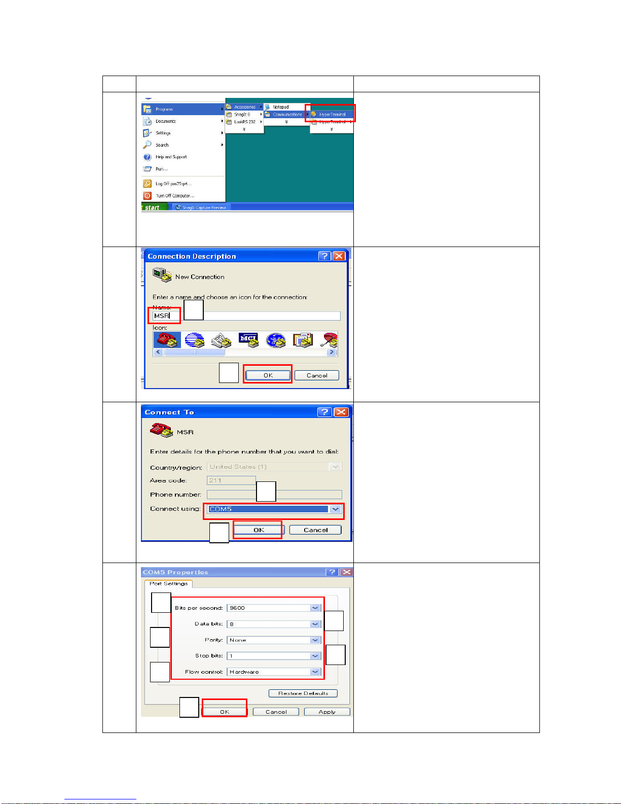
Item Photo Description
5
1. Click
“Start”Æ”Program”Æ”Accessories”
Æ “Communications”Æ “Hyper
Terminal”
6
1. Name for the MSR Module(Ex.
MSR)
2. Click “OK”
7
1. Set “Connect using” as COM5
2. Click “OK”
8
1. Set Bits per second: 9600
2. Data bits: 8
3. Parity: None
4. stop bits: 1
5. Flow control: Hardware
6. Click “OK”
1
2
3
4
5 6
1
2
2
1
Page 41
41/68 Version 1.1
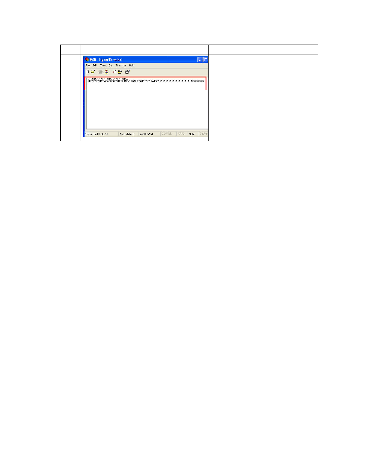
Item Photo Description
9
1. Stripe the MSR card to Reader and
card information will be shown on the
screen
Page 42
42/68 Version 1.1
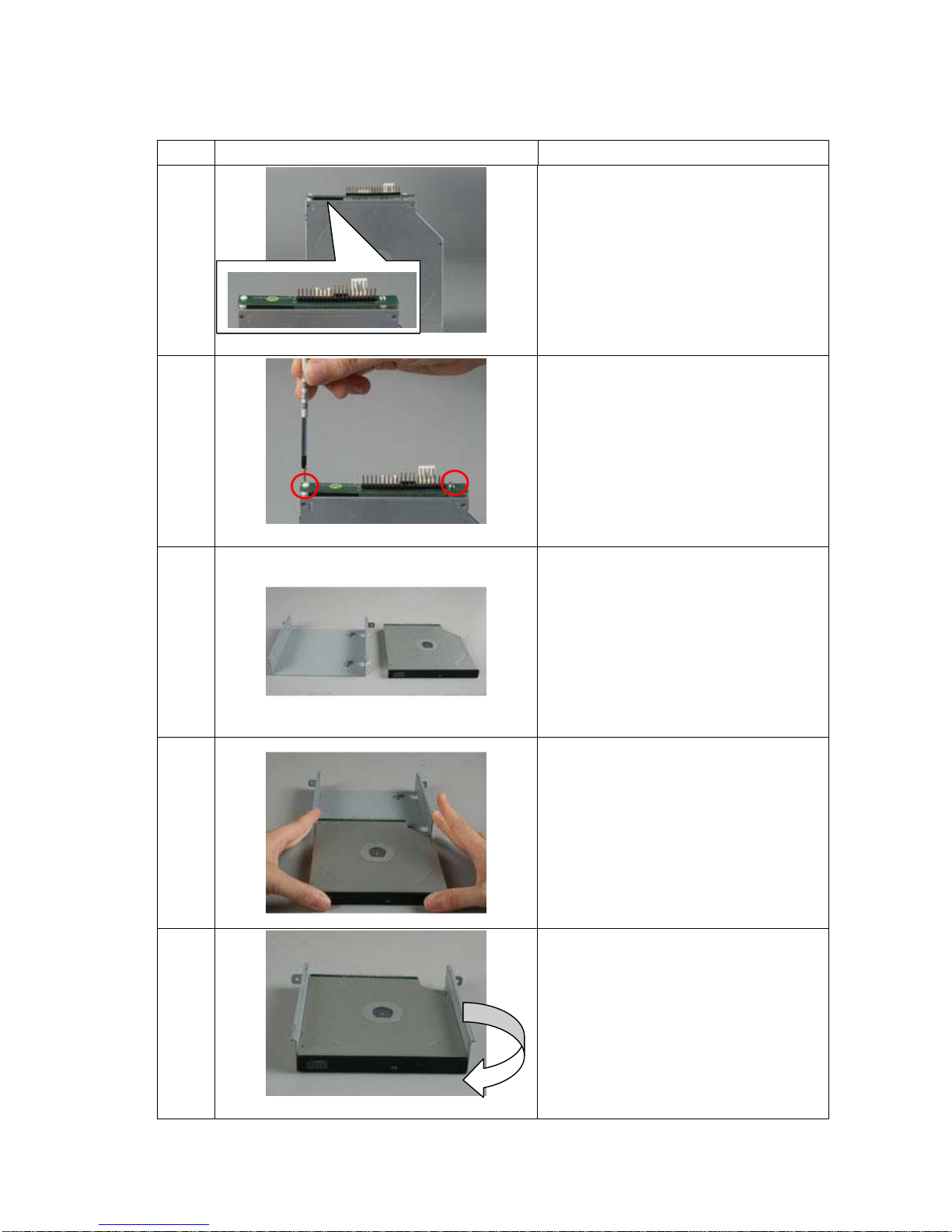
3.4.4 CD-ROM
Item Photo Description
1
1. Connect converter board to
CD-ROM
2
1. Fasten 2 screws on the converter
board
3
1. Take out CD-ROM chassis
4
1. Push CD-ROM into chassis
5
1. Right turn CD-ROM 90 degree to
the side view
Page 43
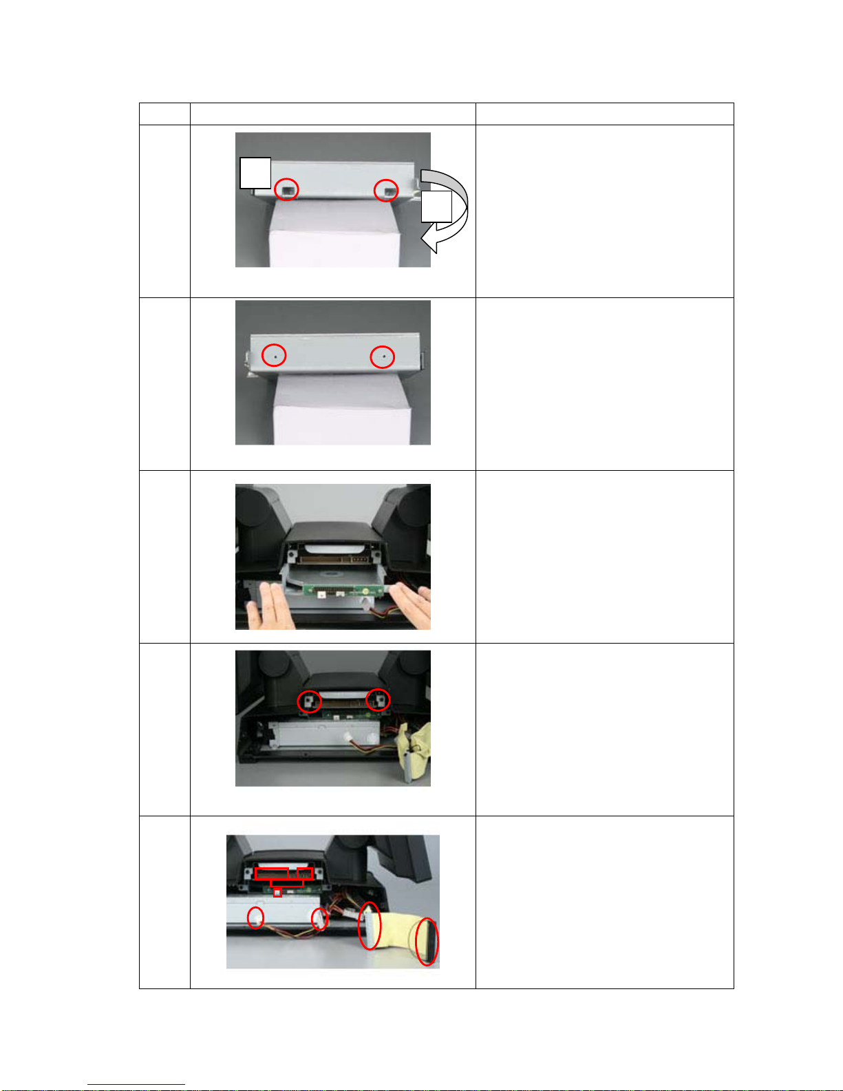
43/68 Version 1.1
Item Photo Description
6
1. Fasten 2 screws
2. Right turn CD-ROM 180 degree to
another side view
7
1. Fasten 2 screws
8
1. Slide the CD-ROM module into
system
9
1. Fasten 2 screws
10
1. Connect cables follow numbers
listed
1
2
1
2
3
4
1
3
2
4
Page 44
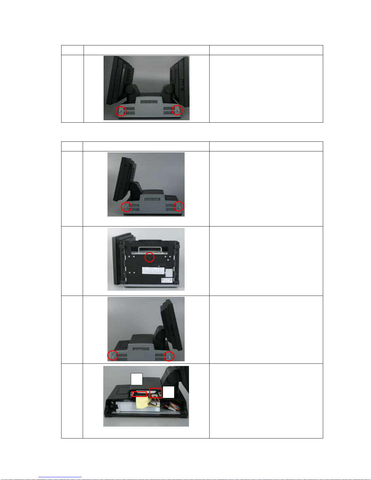
44/68 Version 1.1
Item Photo Description
16
1. Put side cover back and tighten 2
screws
3.4.5 Pole Display-VFD
Item Photo Description
1
Loosen 2 screws and remove side
cover
2
1. Move the case to bottom side
2. Loosen the screw
3
1. Move the case to the other side
2. Loosen 2 screws
4
1. Pull out IDE cable
2. Pull out power cable
1
2
Page 45
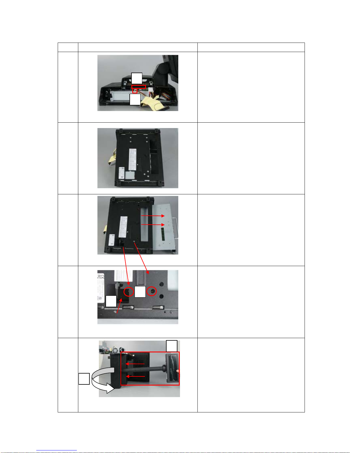
45/68 Version 1.1
Item Photo Description
5
1. Pull out IDE cable
2. Pull out power cable
6
1. Move the case to bottom side
7
1. Pull out metal case
8
1. Remove 2 screws
2. Remove plastic cover
9
1. Move system to VFD side
2. Locate VFD at plastic cover
position and have power cable go
through the cover
3. Right turn to bottom side
1
2
2
3
Cable
1
2
Page 46
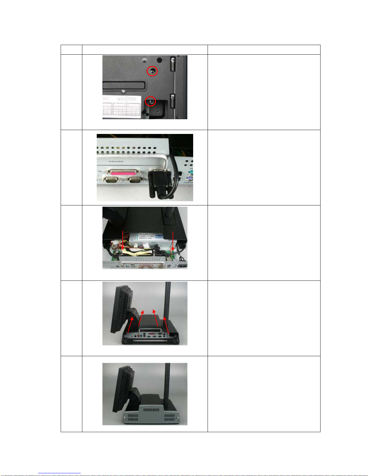
46/68 Version 1.1
Item Photo Description
10
1. Fasten 2 screws at bottom side
11
1. Connect RS-232 cable to COM 4
12
1. Press all cables down
13
1. Push in the metal case
14
1. Put side cover back and tighten 2
screws
Page 47
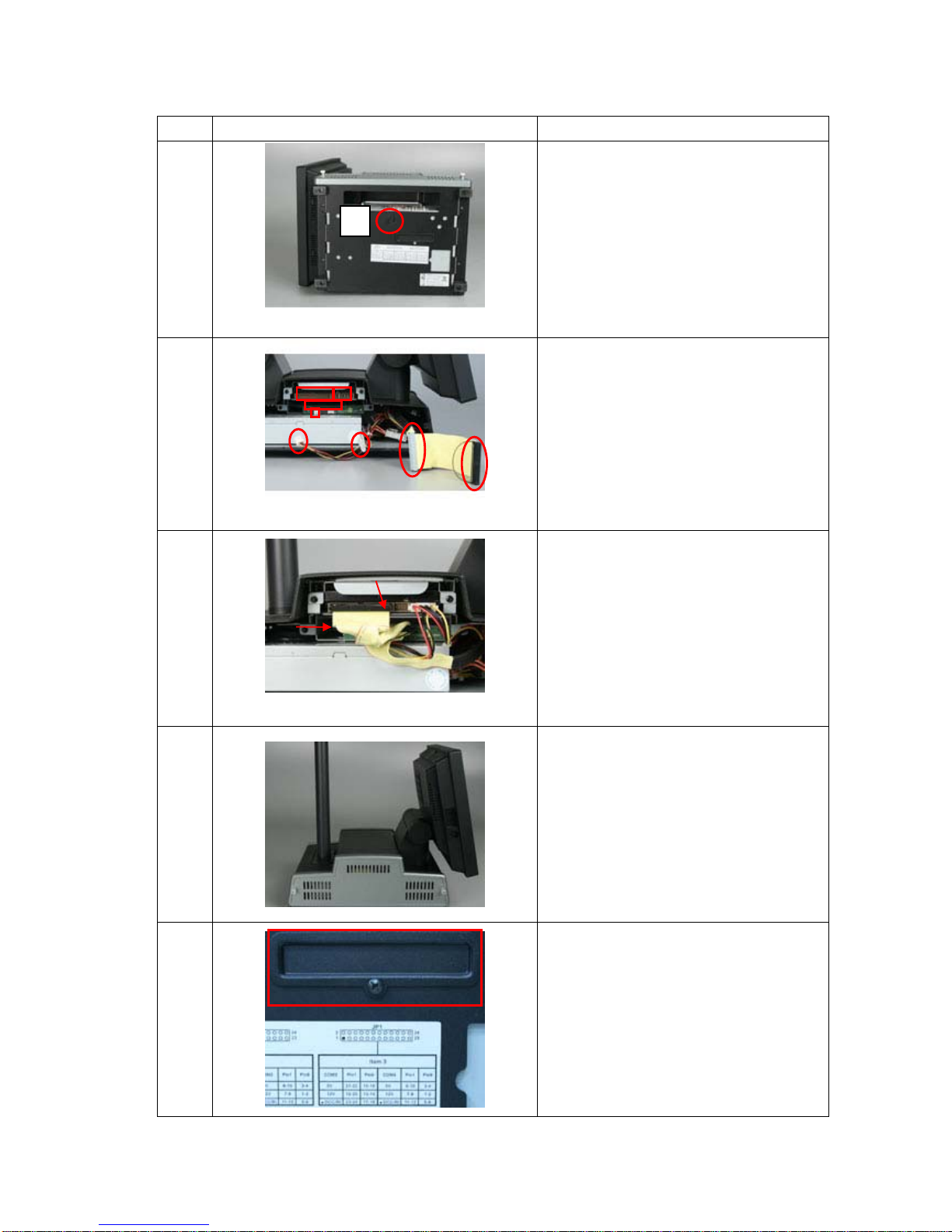
47/68 Version 1.1
Item Photo Description
15
1. Move the case to bottom side
2. Tighten the screw
16
2. Connect cables follow numbers
listed
17
1. Upper IDE cable with red line at
right side
2. Lower IDE cable with red line at
left side
18
1. Put side cover back and tighten 2
screws
19
1. Move the case to bottom side
2. Remove 1 screw to open jumper
cover
2
1
2
3
4
1
3
2
4
Page 48
48/68 Version 1.1
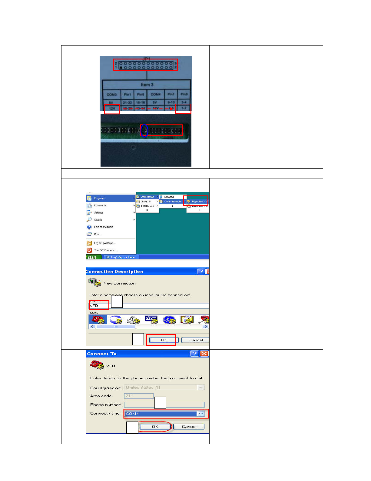
Item Photo Description
20
1. Adjust JP1, 12V and short 1-2 at Pin
9
VFD Utility Verification
Item Photo Description
21
1. Click
“Start”Æ”Program”Æ”Accessories”
Æ “Communications”Æ “Hyper
Terminal”
22
1. Name for the MSR Module(Ex.
VFD)
2. Click “OK”
23
1. Set “Connect using” as COM4
2. Click “OK”
1
2
2
1
Page 49
49/68 Version 1.1
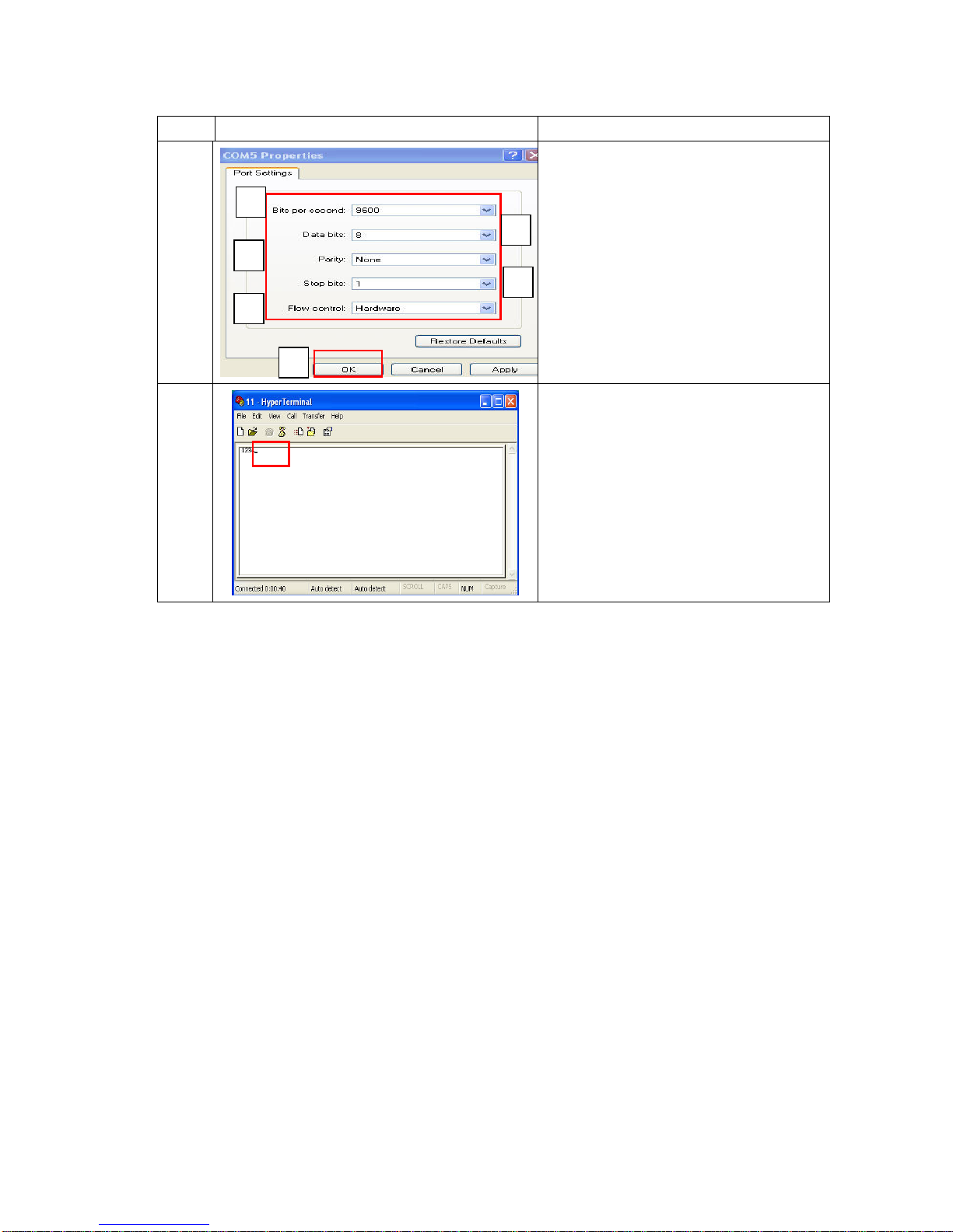
Item Photo Description
24
3. Set Bits per second: 9600
4. Data bits: 8
5. Parity: None
6. stop bits: 1
7. Flow control: Hardware
8. Click “OK”
25
1. Key in any letter or Numbers( Ex.
Test)
2. The letters will show on the VFD
screen
1
2
3
4
5
6
Page 50
50/68 Version 1.1
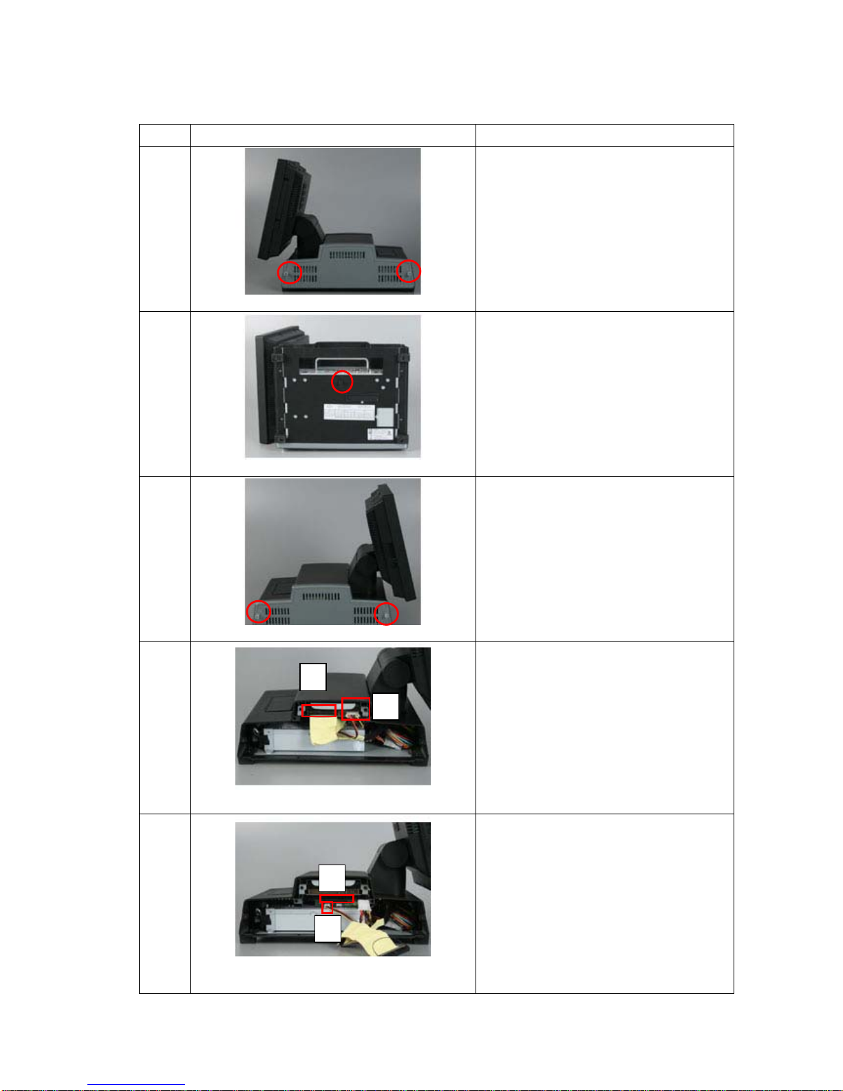
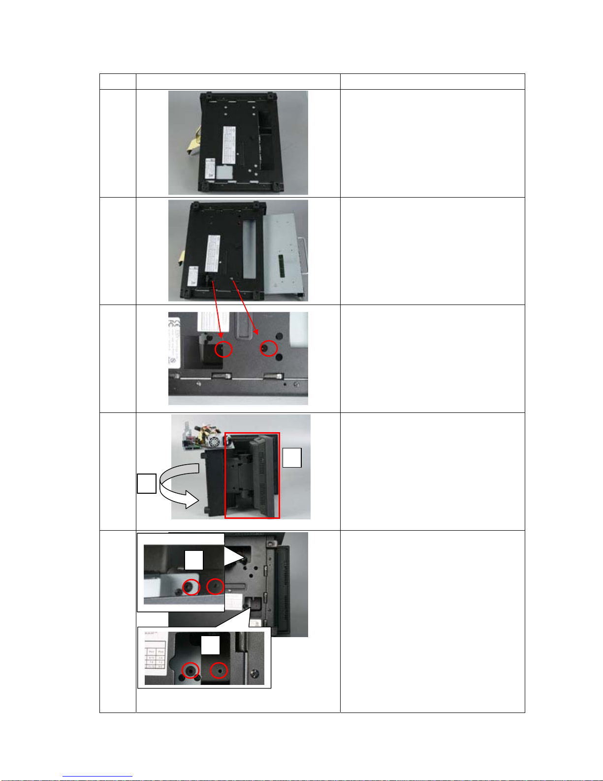
3.4.6 2nd Display
Item Photo Description
1
Loosen 2 screws and remove side
cover
2
1. Move the case to bottom side
2. Loosen the screw
3
1. Move the case to the other side
2. Loosen 2 screws
4
1. Pull out IDE cable
2. Pull out power cable
5
1. Pull out IDE cable
2. Pull out power cable
1
2
1
2
Page 51
51/68 Version 1.1
Item Photo Description
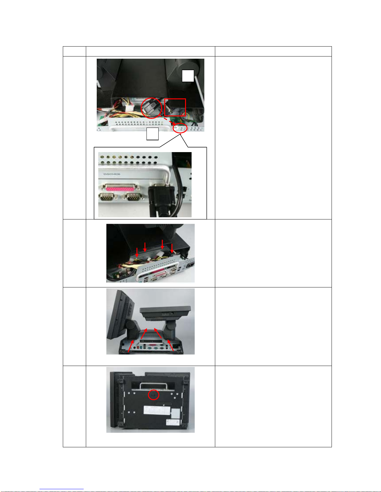
6
1. Move the case to bottom side
7
1. Pull out metal case
8
1. Remove 2 screws
2. Remove plastic cover
9
1. Move system to 2nd display side
2. Locate 2nd display at plastic cover
position
3. Right turn to bottom side
10
1. Fasten 2 screws at bottom side
2. Fasten another 2 screws at bottom
side
1
2
2
3
Page 52
52/68 Version 1.1
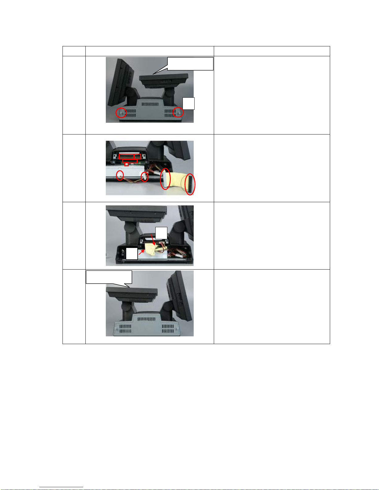
Item Photo Description
11
1. Turn the case to top side
2. Connect VGA cable
3. Pass RS-232 cable through the
chassis and connect to COM 4
12
1. Press all cables down
13
1. Push in the metal case
14
1. Tighten the bottom screw
2
3
Page 53
53/68 Version 1.1
Item Photo Description
15
1. Move system to side view
2. Put side cover back and tighten 2
screws
16
1. Connect cables follow numbers
listed
17
1. Upper IDE cable with red line at
right side
2. Lower IDE cable with red line at
left side
18
1. Move to side part
2. Put side cover back and tighten 2
screws
2ndDispla
y
1
2
3
4
1
3
2
4
2
1
2nd Displa
y
2
Page 54

54/68 Version 1.1
2nd Display with touch panel
If you order the 2nd display comes with touch panel, please remember to adjust COM
4 jumper setting, select 9-10 of Pin1 at the bottom side of POS system. So that it could
supply 5V DC on pin 1 for touch panel.
Note:
1. The pin 6 of 2nd VGA cable supply 12V DC power directly, so it doesn’t need to
connect with any external power adapter.
2. The VGA port of the POS system is designed specifically for our display kits. So
please do not connect to any normal monitor or LCD.
Pin Assignment
1 RED
2 GREEN
3 BLUE
4 Monitor ID bit 2
5 Ground
6 +12VDC Output
7 GREEN Ground
8 BLUE Ground
9 no pin (keyway)
10 Sync Ground
11 Monitor ID bit 0
12 Monitor ID bit 1
13 Horizontal Sync
14 Vertical Sync
15 Not Used
Page 55
55/68 Version 1.1
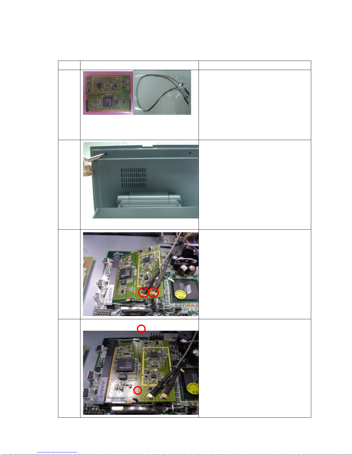
3.4.7 Mini PCI Wireless LAN
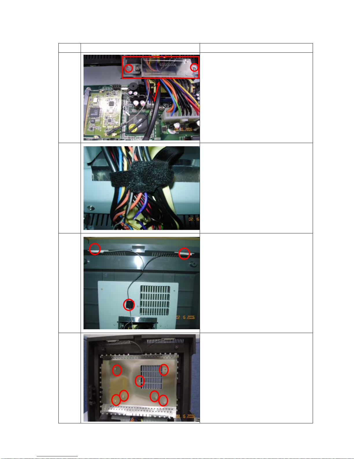
Item Photo Description
1
Mini PCI Wireless LAN
2
1. Use screw driver to open upper case
2. Remove 2 screws
3
1. Insert the WLAN card to mini PCI
slot
2. Connect the Antenna to card as red
mark
4
1. Press Wireless LAN Card
2. Make sure connected well
Page 56
56/68 Version 1.1
Item Photo Description
5
1. Remove 2 screws from cover
bracket
2. Remove cover bracket
3. Antenna cable needs to go under
cover bracket
4. Remove EMI cover
6
1. Tied Antenna cable with other cables
7
1. Stick the Antenna by temped tape to
back cover
8
1. Tighten 7 screws on EMI cover.
Page 57
57/68 Version 1.1
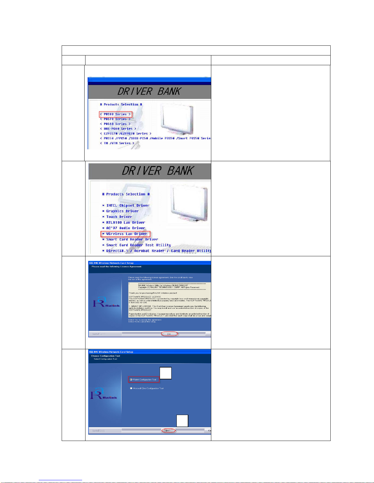
Mini PCI Wireless Lan Driver Installation
Item Photo Description
9
1. Insert driver CD and select POS 8
series
10
1. Select “Wireless Lan Driver”
11
1. Click “Yes”
12
1. Select “Ralink Configuration T ool”
2. Click “Next”
2
1
Page 58
58/68 Version 1.1
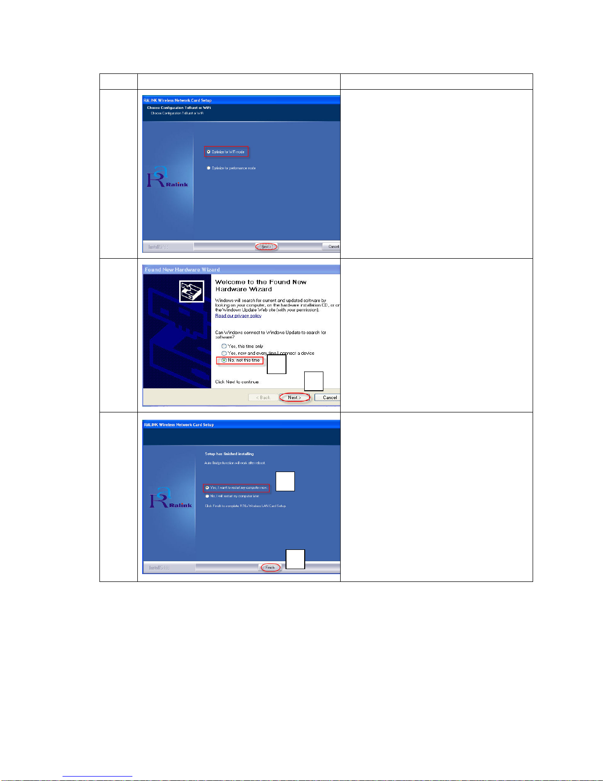
Item Photo Description
13
1. Select “Optimize for WiFi mode”
2. Click “Next”
14
1. Select “No, not this time”
2. Click “Next”
15
1. Select “Yes, I want to restart my
computer now”
2. Click “Finish”
1
1
2
2
Page 59

59/68 Version 1.1
BIOS setup
Chapter 4
CHAPTER
Page 60
60/68 Version 1.1
Chapter 4 – BIOS setup
4.1 P4 M/B
(POS87-2EB-478, POS87-5EB-478)
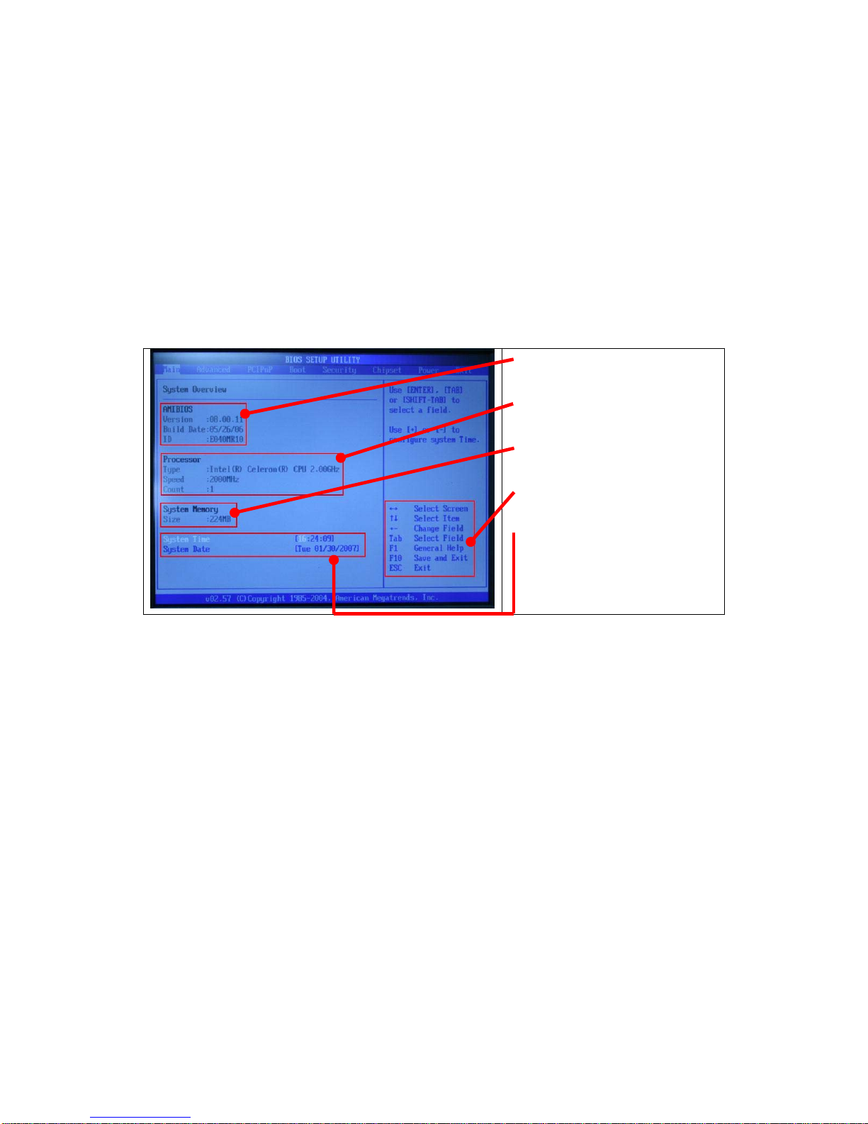
4.1.1 Starting Setup
To enter BIOS, please click at “Delete” when booting up the POS system and
you will see the picture below.
z BIOS Information
z CPU Information
z Memory Information
z Function Key
z Time setup
Page 61
61/68 Version 1.1
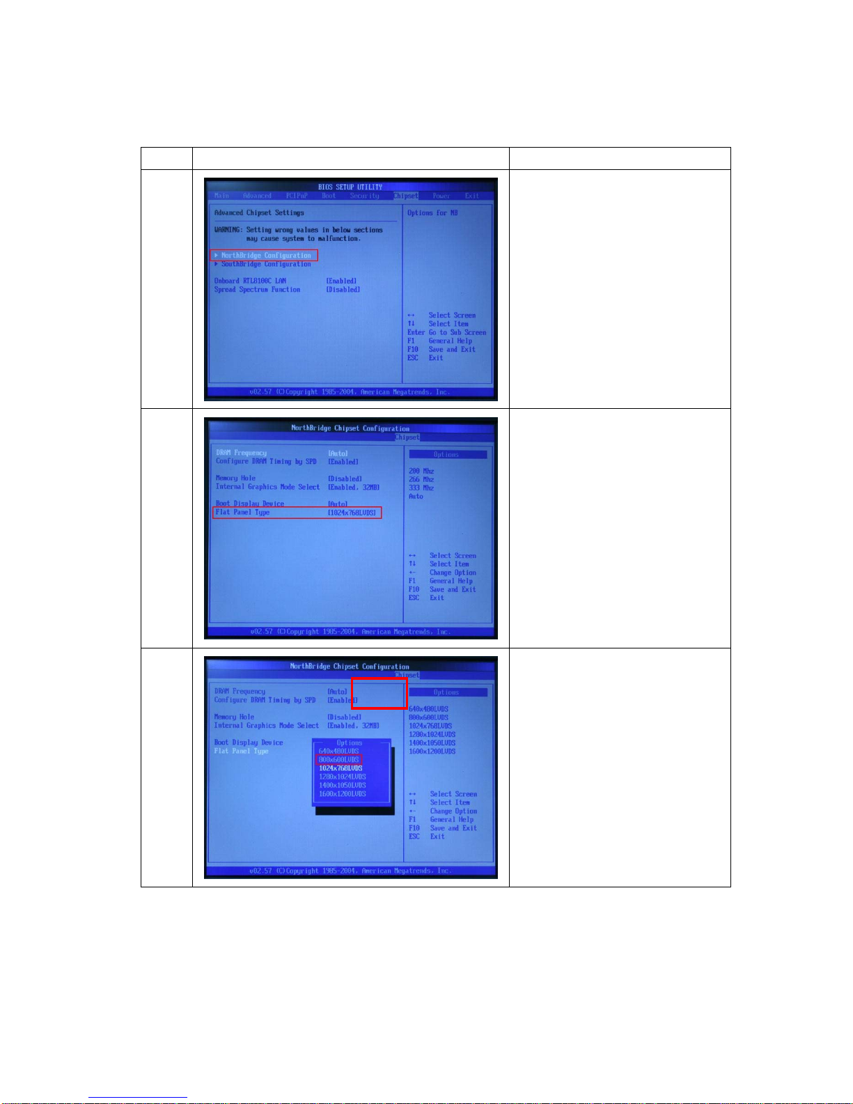
4.1.2 Resolution setup
Item Photo Description
1
Enter “Northbridge
Configuration” of “Chipset”
2 Enter “Flat Panel Type”
3
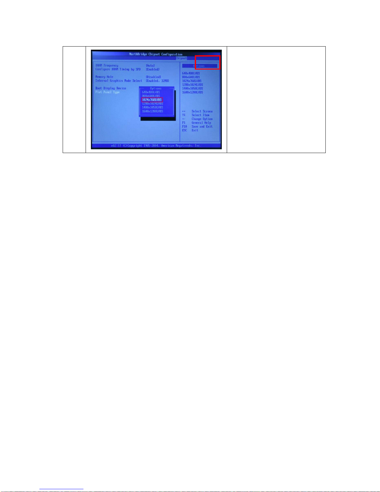
Choose your panel type
12” – 800x600
15” – 1024x768
12”
Page 62
62/68 Version 1.1
15”
Page 63

63/68 Version 1.1
M/B Information
CHAPTER
Chapter 5
Page 64
64/68 Version 1.1
Chapter 5 – M/B Information
5.1 M/B Jumper Setting
(POS87-2EB-478, POS87-5EB-478)
Clear CMOS Setup
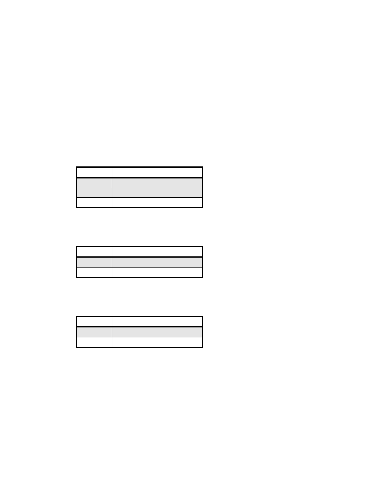
If you want to clear the CMOS Setup (for example forgot the password you
should clear the setup and then set the password again.), you should close the
JP1 about 3 seconds, then open again. Set back to normal operation mode.
JP1: Clear CMOS Setup
JP1 Description
1-2 Keep CMOS Setup
(Normal Operation)
2-3 Clear CMOS Setup
Compact Flash Card Master/Slave Mode Setting
JP2: Master/Slave Mode Setting
JP2 Description
OPEN SLAVE
SHORT MASTER
Keyboard Setting
JP3: Keyboard Setting
JP3 Description
Open Disabled
Short Enabled
Page 65
65/68 Version 1.1
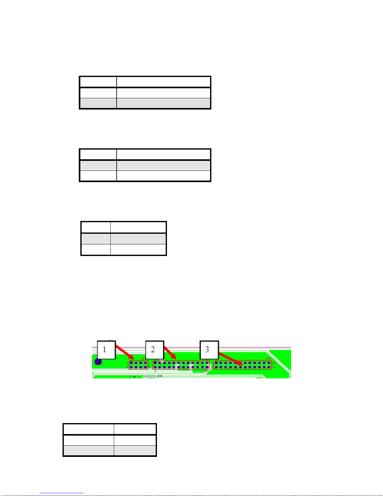
DCD or DTR Select of COM6 Setting
JP4: DCD/DTR Setting
JP4 Description
1-2 DCD
2-3 DTR
Pentium 4/Mobile P4/Mobile P4-M Select
JP7: Pentium 4/Mobile P4/Mobile Pentium 4-M Select
JP7 Description
1-2 Pentium 4
2-3 Mobile Celeron/P4-M
LCD Power setting
JP8: This jumper is for the setting of LCD panel voltage.
JP8 Description
1-2 +3.3V
3-4 +5V
5.2 COM & RJ-11 Jumper Settings
Before installing the cash drawer or any peripherals which use COM ports,
please make sure you configure all the “Power” settings accurately.
1. Cash Drawer
Cash Drawer JP4
12V 5-6,7-8
24V 1-2,3-4
Page 66
66/68 Version 1.1
2. COM1 & COM2
COM 1 Pin 1 Pin9 COM 2 Pin1 Pin9
5V 21-22 15-16 5V 9-10 3-4
12V 19-20 13-14 12V 7-8 1-2
DCD/RI 23-24 17-18 DCD/RI 11-12 5-6
3. COM3 & COM4
COM 3 Pin 1 Pin9 COM 4 Pin1 Pin9
5V 21-22 15-16 5V 9-10 3-4
12V 19-20 13-14 12V 7-8 1-2
DCD/RI 23-24 17-18 DCD/RI 11-12 5-6
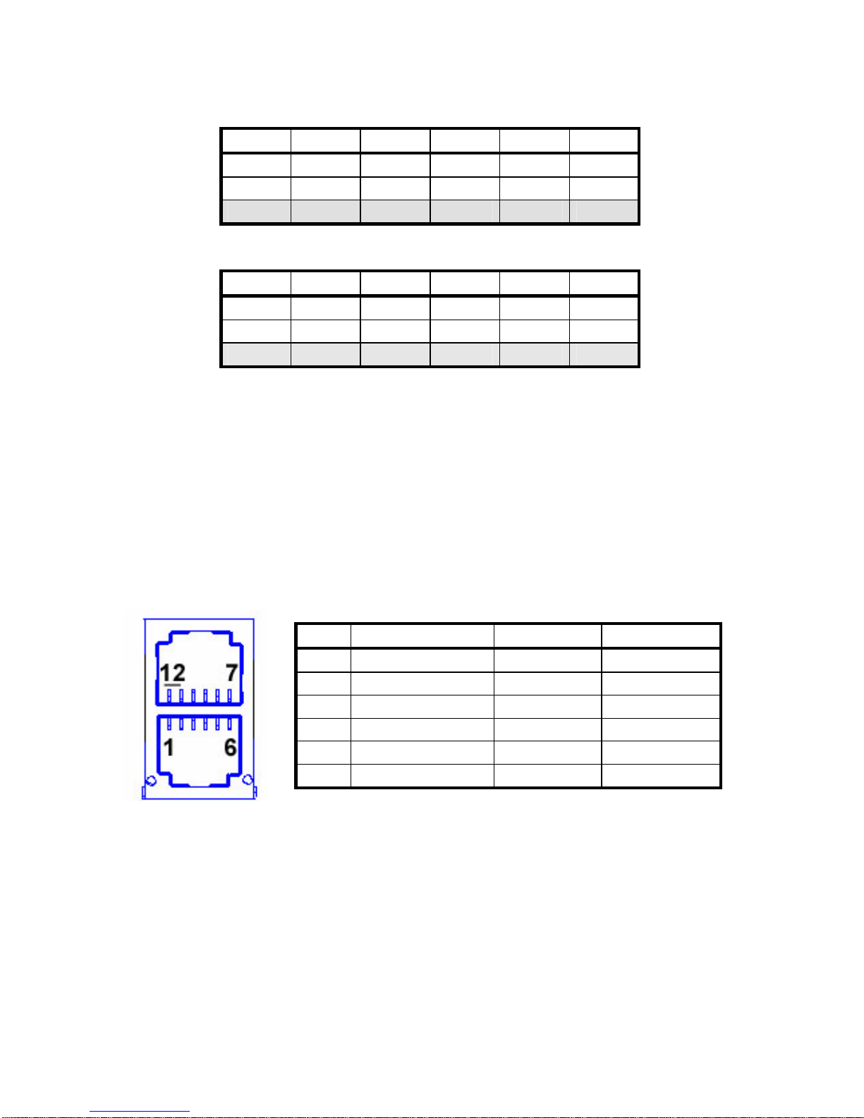
5.3 Cash Drawer Introduction
The POS system provides RJ-11 x 2 for cash drawer. And both could support
12V & 24V cash drawer which could be configured on the bottom side of POS
system.
Pin Assignment
I/O Address
I/O Address: 280H (For both Cash Drawers which are controlled by data bit)
Cash Drawer 1: DIN0=>Bit0, DOUT0=>Bit4
Cash Drawer 2: DIN1=>Bit1, DOUT1=>Bit5
Pin Assignment Pin Assignment
1 GND 7 GND
2 DOUT 0 8 DOUT 1
3 DIN 0 9 DIN 1
4 12V/24V 10 12V/24V
5 NC 11 NC
6 GND 12 GND
Page 67

67/68 Version 1.1
Chapter 6
CHAPTER
Reversion
Page 68

68/68 Version 1.1
Chapter 6 – Reversion History
Version Item Descriptions Page
 Loading...