

Kennedy VERSA-BENCH 4806, VERSA-BENCH 6012S, VERSA-BENCH 4804, VERSA-BENCH 6012E, VERSA-BENCH 6006 Assembly & Instruction Manual
Thank you for purchasing this Kennedy product. We produce value-built products for value
conscious users. We welcome any comments or suggestions you may have. Just call or write
the address below. We hope you will continue to nd Kennedy the most complete source for
your tool storage needs.
VERSA-BENCH
®
ASSEMBLY INSTRUCTIONS
STYLE NUMBERS—
BEFORE ASSEMBLY OF YOUR VERSA-BENCH
®
Check carefully to ensure that all parts listed on the reverse side are included. If any are missing, please call
800-413-8665 and ask for the Sales Dept. Do not discard packing material until assembly is complete.
TOOLS REQUIRED
Flat tip screwdriver
7/16” Open end wrench or socket wrench
9/16” Open end wrench or socket wrench
KMC Holdings LLC dba Kennedy Manufacturing Company
1260 Industrial Drive • Van Wert, OH 45891
Phone 800-413-8665 • Fax 419-238-5644 • www.kennedymfg.com
Part No. 527034, Rev. 8/07
4804
4806
6006
6012E
X
S
T
U
Y
Y
V
R
Q
W
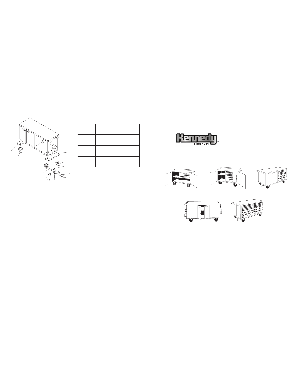
Versa-Bench® Towing Package Assembly Instructions
Note: To be used in conjuction with Versa-Bench Assembly Instructions
ASSEMBLY SUPPLY LIST
QTY KEY PART DESCRIPTION
1 (Q) Bottom pan front reinforcement with cross
plate (has 3 sets of bolt hole piercings)
2 (R) Swivel Casters
2 (S) Rigid Casters
16 (T) 3/8” x 1-1/2” Hex Head Bolts
16 (U) 3/8” Lock Nuts
1 (V) Tongue Plate
4 (W) 3/8-16 x 1” Bolts
1 (X) Rear bottom pan reinforcement
(has 2 sets of bolt hole piercings)
1 (Y) Towing tongue, pin, (2) cotter keys
With Versa-Bench laying on back, proceed as follows:
1. Position the front reinforcement with cross plate (Q) under front of bench as shown, aligning the bolt holes of
both the front reinforcement and bench. Fasten the swivel casters (R) and the front reinforcement to the bench
with (8) 3/8” x 1-1/2” hex head bolts (T) and (8) 3/8” lock nuts (U). Bolt heads should be inside the bench, lock
nuts below the caster plate.
2. Bolt tongue plate (V) to the front reinforcement cross plate with (4) 3/8-16 x 1” bolts.
3. Align towing tongue (Y) tongue plate (V), insert pin and hair pin (Y).
4. Fasten the rear bottom pan reinforcement (X) and rigid casters (S) to the bench with remaining 3/8” bolts
and lock nuts.
5. Set the bench upright and proceed with instruction number (7) of the Versa-Bench Assembly Instruction on
previous page.
6012S
K
G
H
J
I
N
A
L
M
D
P
O
C
B
E
F
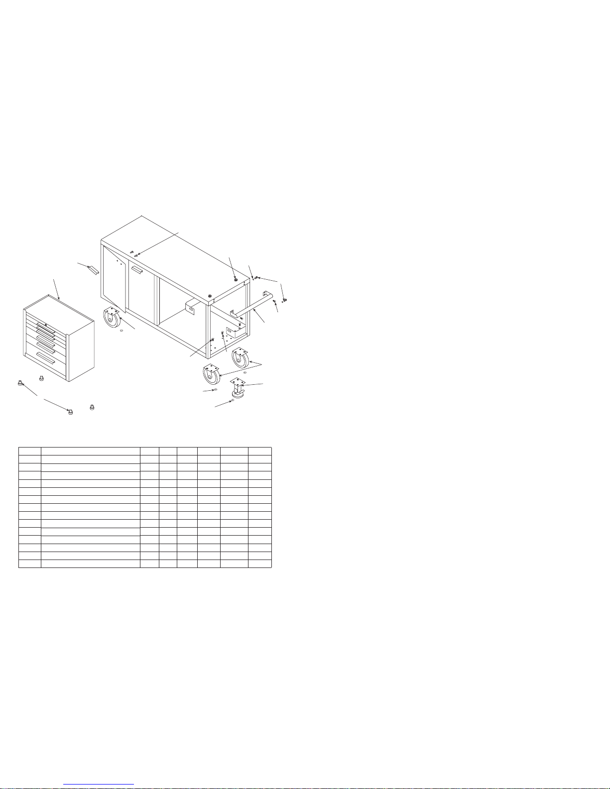
ASSEMBLY SUPPLY LIST
KEY PART DESCRIPTION MODEL NUMBER
4804 4806 6006 6012E 6012ED 6012S
A Kennedy Tool Chest 0 1 1 2 2 2
B Chrome Plated Push Handle 1 1 1 1 1 1
C 1/4” x 3/4” Hex Head Bolts 4 4 4 4 4 4
D Double Head Nut 2 2 2 2 2 2
E 8 x 2” Swivel Casters 2 2 2 2 2 2
F Floor Lock 1 1 1 1 1 1
G, I 3/8 x 3/4” Hex Head Bolts 20 20 20 20 20 20
H, J 3/8” Hex Lock Nuts 20 20 20 20 20 20
K 8 x 2” Rigid Casters 2 2 2 2 2 2
L “L” Shaped Aluminum Door Handles 2 2 4 4 8 2
M 1/2” Hex Head Screws 4 4 8 8 16 4
N White Plastic Feet 0 4 4 8 8 8
O 1/4” x 3/4” Round Head Screw 0 2 2 4 4 4
P Washer 0 2 2 4 4 4
Versa-Bench® Assembly Instructions
Note: For towing package assembly, refer to assembly instructions on back page.
1. Remove tool chest(s) (A) from Versa-Bench, set aside. Does not apply to model 4804.
2. Fasten chrome push handle (B) to end of bench as shown using (4) 1/4” x 3/4” hex head bolts (C) and
(2) double head nut (D). Note: 4804, 4806 push handle assembles to left ends into extruded holes with 1/4”
thread cutting bolt.
3. Lift bench with a fork lift or lay on its back on shipping carton to install swivel casters (E) and oor lock (F).
Remove bolts from wood shipping blocks from inside bottom of the Versa-Bench.
4. Fasten swivel casters (E), as shown, at the same end as the push handle (B) with (8) 3/8” x 3/4” hex bolts (G)
and (8) 3/8” lock nuts (H). Bolt head should be inside bench, lock nut under bench.
5. Fasten the oor lock (F), as shown between the swivel casters (E) with (4) 3/8” x 3/4” hex bolts (I) and
(4) 3/8” lock nuts (J). Bolt head should be inside bench, lock nut under bench.
6. Fasten rigid casters (K) to opposite end of bench with (8) 3/8” x 3/4” hex bolts and (8) 3/8” lock nuts.
Carefully set bench upright.
7. Fasten each door handle (L) to each door with (2) 1/2” hex head screws (M). Center the handle on the two
holes provided in the door. Fasten the screws thru the holes into the base of the handle.
8. Tool chest installation: Does not apply to model 4804. Remove tool chest(s) (A) from carton(s). Supplies are
in an envelope in a drawer.
9. Snap (4) plastic feet (grommets) (N) in place, up thru the four holes in the bottom of each tool chest.
10. Slide tool chest into position inside the bench and fasten with (2) 1/4” x 3/4” round head screws (O) with
washers (P) thru the slots in bench compartment wall into the threaded holes in the tool chest back.
 Loading...