

Page 1
40" ELECTRIC RANGE INSTALLATION INSTRUCTIONS
INSTALLATION INSTRUCTIONS
40" ELECTRIC RANGE
INSTALLATION AND SERVICE MUST BE PERFORMED BY A QUALIFIED INSTALLER.
IMPORTANT: SAVE FOR LOCAL ELECTRICAL INSPECTOR'S USE.
READ AND SAVE THESE INSTRUCTIONS FOR FUTURE REFERENCE.
United States
FOR YOUR SAFETY: Do not store or use gasoline or other
ammable vapors and liquids in the vicinity of this or any other appliance.
Table of Contents
Important Safety Instructions .......................................2-3
Product Dimensions ....................................................... 4
Cabinet Dimensions ....................................................... 5
Electrical Requirements.................................................. 6
Power Supply Cord......................................................... 7
Important Note to the Consumer
1. Keep these instructions with your owner's guide for
future reference.
2. When using any appliance generating heat, there are
safety precautions you must follow. These precautions
are explained in your Use and Care manual. Read
your manual carefully.
3. Be sure your appliance is installed and grounded by a
qualied installer or service technician.
Cabinet Construction ...................................................... 7
Leveling the Range......................................................... 8
Anti-Tip Brackets Installation ..................................... 9-10
Check Operation............................................................11
Serial Plate Location (Model & Serial Number) .............11
Notes ............................................................................ 12
Important Notes to the Installer
1. Read all instructions contained in these installation
instructions before installing range.
2. Remove all packing material from the oven and the
drawer compartments before connecting the electrical
supply to the range.
3. The anti-tip bracket supplied with the appliance must
be installed.
4. Observe all governing codes and ordinances.
5. Be sure to leave these instructions with the consumer.
Printed in United States
P/N 809018801 (1701) Rev.B
English – pages 1-12
Español – pages 13-24
Français – pages 25-36
1
Page 2
40" ELECTRIC RANGE INSTALLATION INSTRUCTIONS
IMPORTANT SAFETY INSTRUCTIONS
This appliance must be installed, grounded, and serviced by a qualied installer or service technician.
This manual contains important safety symbols and instructions. Please pay attention to these symbols and follow all
instructions given. Do not attempt to install or operate your appliance until you have read the safety precautions in this
manual. Safety items throughout this manual are labeled with a WARNING or CAUTION statement based on the risk type.
Warnings and important instructions appearing in this guide are not meant to cover all possible conditions and situations
that may occur. Common sense, caution, and care must be exercised with installing, maintaining, or operating your
appliance.
This is the safety alert symbol. It is used to alert you to potential personal injury hazards. Obey all safety messages
that follow this symbol to avoid possible injury or death.
Indicates a potentially hazardous situation which, if not avoided, may result in death or serious injury.
Indicates a potentially hazardous situation which, if not avoided, may result in minor or moderate
injury.
IMPORTANT: Indicates installation, operation, maintenance, or valuable information that is not hazard related.
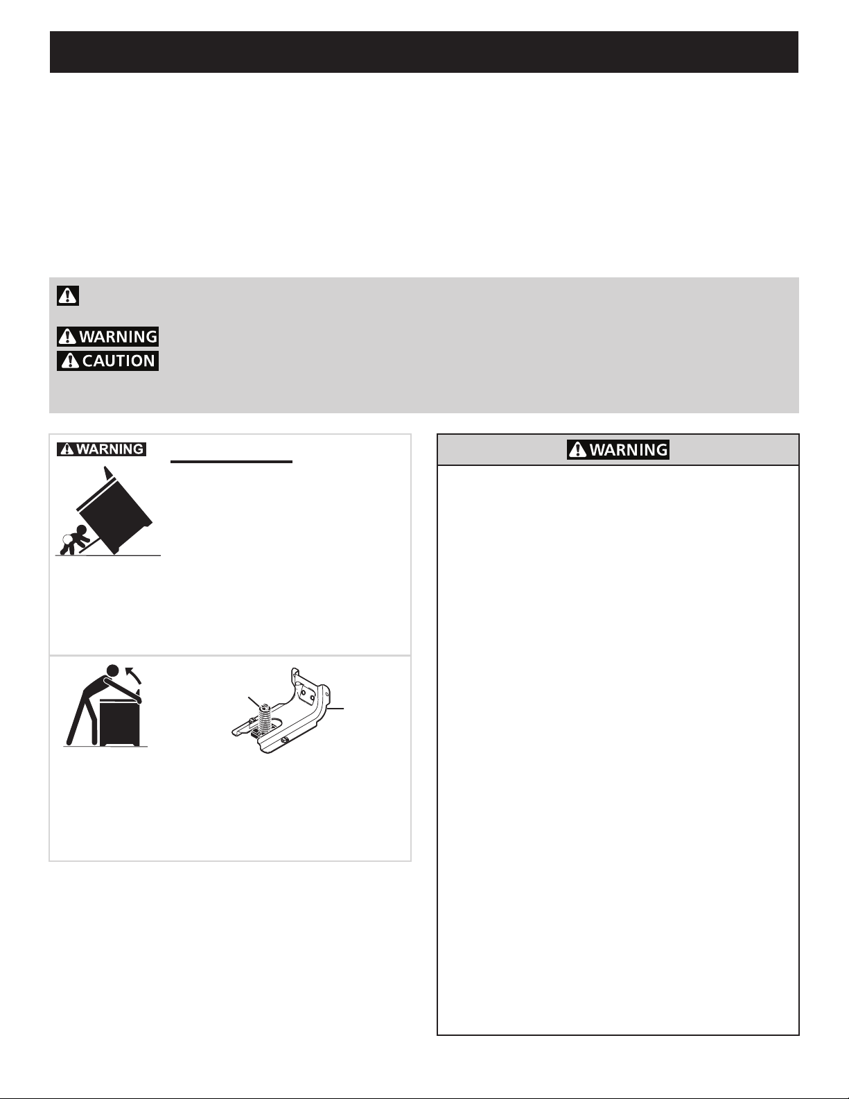
Tip Over Hazard
• A child or adult can tip the range
and be killed.
• Verify the anti-tip device has been
installed to floor or wall.
• Ensure the anti-tip device is re-engaged to floor or wall
when the range is moved.
• Do not operate the range without the anti-tip device in
place and engaged.
• Failure to follow these instructions can result in death or
serious burns to children and adults.
Range
leveling leg
Anti-tip
bracket
To check if the anti-tip bracket is installed properly, use both
arms to grasp the rear edge of the range back. Carefully
attempt to tilt range forward. When properly installed, the range
should not tilt forward.
Refer to the anti-tip bracket installation instructions supplied
with your range for proper installation.
• Excessive Weight Hazard--Use two or more
people to move and install range. Failure to follow
this instruction can result in back or other injury.
• Storage In or On Appliance—Flammable
materials should not be stored in an oven or
microwave, near surface burners or elements, or
in the storage or warmer drawer (if equipped). This
includes paper, plastic, and cloth items, such as
cookbooks, plastic ware, and towels, as well as
ammable liquids. Do not store explosives, such as
aerosol cans, on or near the appliance.
• Do not leave children alone - Children should
not be left alone or unattended in the area where
appliance is in use. They should never be allowed
to sit or stand on any part of the appliance,
including the storage drawer, lower broiler drawer,
warmer drawer, or lower double oven.
• Do not store items of interest to children in the
cabinets above the appliance or on the backguards
of ranges. Children climbing on or near the
appliance to reach items could be seriously injured.
• Stepping, leaning, or sitting on the door or drawers
of this appliance can result in serious injuries and
also cause damage to the appliance.
• Do not use oven or warmer drawer (if equipped) for
storage.
• Never use your appliance as a space heater to
heat or warm the room. Doing so may result in
carbon monoxide poisoning and overheating of the
appliance.
• Do not store or use gasoline or other ammable
vapors and liquids in the vicinity of this or any other
appliance.
2
Page 3

40" ELECTRIC RANGE INSTALLATION INSTRUCTIONS
IMPORTANT INSTRUCTIONS FOR UNPACKING AND
INSTALLATION
Read and follow the below instructions and precautions
for unpacking, installing, and servicing your appliance:
• Destroy the carton and plastic bags after unpacking the
appliance. Never allow children to play with packaging
material. Do not remove the wiring label and other
literature attached to the appliance. Do not remove
model/serial number plate.
• Cold temperatures can damage the electronic control.
When using this appliance for the rst time, or when the
appliance has not been used for an extended period of
time, be sure the appliance has been in temperatures
above 32ºF (0ºC) for at least 3 hours before turning on
the power to the appliance.
• Never modify or alter the construction of the appliance
by removing the leveling legs, panels, wire covers, antitip brackets/screws, or any other part of the appliance.
• Proper Installation—Be sure your appliance is properly
installed and grounded by a qualied technician. In the
United States, install in accordance with the National
Fuel Gas Code ANSI Z223.1/NPFA No. 54, latest
edition and National Electrical Code NFPA No. 70
latest edition, and local electrical code requirements.
In Canada, install in accordance with CAN/CGA
B149.1 and CAN/CGA B149.2 and CSA Standard
C22.1, Canadian Electrical code, Part 1-latest editions
and local electrical code requirements. Install only
per installation instructions provided in the literature
package for this appliance.
• The installation of appliances designed for
manufactured (mobile) home installation must
conform with Manufactured Home Construction and
Safety Standard, title 24CFR, part 3280 [Formerly
the Federal Standard for Mobile Home Construction
and Safety, title 24, HUD (part 280)] or when
such standard is not applicable, the Standard for
Manufactured Home Installation 1982 (Manufactured
Home Sites, Communities and Setups), ANSI Z225.1/
NFPA 501A-latest edition, or with local codes in United
States and with CAN/CSA-Z240 MH in Canada.
• Before installing the range in an area covered with
linoleum or any other synthetic oor covering, make
sure the oor covering can withstand heat at least
90°F (32,2°C) above room temperature without
shrinking, warping or discoloring. Do not install the
range over carpeting unless you place an insulating
pad or sheet of ¼" (0,64 cm) thick plywood between
the range and carpeting.
• Make sure the wall coverings and cabinet materials
around the range can withstand the heat generated by
the appliance.
• To eliminate the risk of burns or re by reaching over
heated surface units, cabinet storage space above the
surface unit should be avoided. If cabinet storage is to
be provided the risk can be reduce by installing a range
hood that projects horizontally a minimum of 5 inches
beyond the bottom of the cabinet.
• Do not obstruct airow at the oven vent, around
the base, or beneath the lower front panel of the
appliance. This appliance requires fresh air for proper
operation.
• Be sure to have an appropriate foam-type re
extinguisher available, visible, and easily accessible
located near the appliance.
IMPORTANT INSTRUCTIONS FOR SERVICE AND
MAINTENANCE
• Do not repair or replace any part of the appliance
unless specically recommended in the manuals. All
other servicing should be done only by a qualied
technician. This reduces the risk of personal injury
and damage to the appliance.
• Always contact your dealer, distributor, service agent,
or manufacturer about problems or conditions you do
not understand.
• Ask your dealer to recommend a qualied technician
and an authorized repair service. Know how to
disconnect the power to the appliance at the circuit
breaker or fuse box in case of an emergency.
• Remove the oven door from any unused oven if it is to
be stored or discarded.
• Do not touch a hot oven light bulb with a damp cloth.
Doing so could cause the bulb to break. Handle
halogen lights (if equipped) with paper towels or soft
gloves. Disconnect the appliance or shut off the power
to the appliance before removing and replacing the
bulb.
3
Page 4
40" ELECTRIC RANGE INSTALLATION INSTRUCTIONS
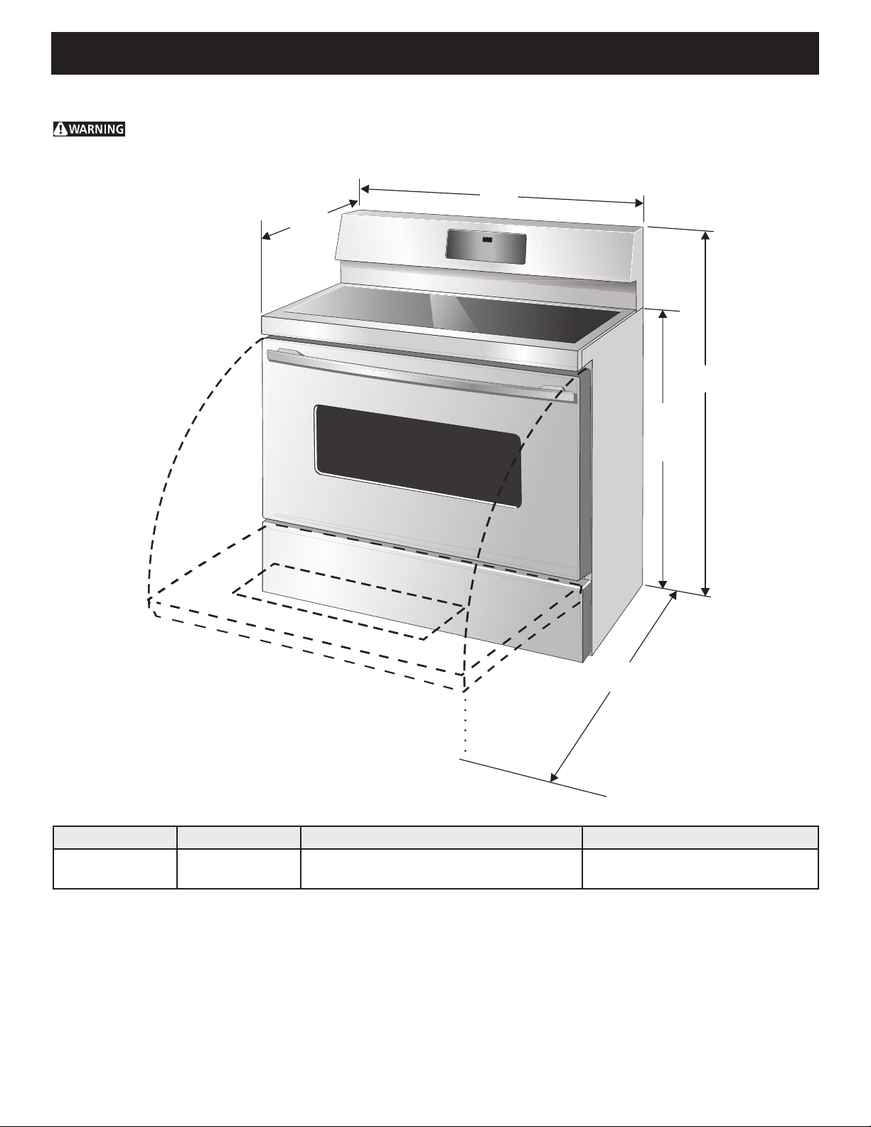
Product Dimensions
Do not install the unit in the cabinet before reading next two pages.
B
C
A
37"
(94 cm)
feet
extended
D
Figure 1: Product Dimensions
A. HEIGHT B. WIDTH C. DEPTH TO FRONT OF RANGE D. DEPTH WITH DOOR OPEN
49" (124.5 cm) 40" (101.6 cm)
28 1/2" (72.4 cm) max with handle
26 1/16" (66.2 cm)
4
47 3/4" (121.3 cm)
Page 5
40" ELECTRIC RANGE INSTALLATION INSTRUCTIONS
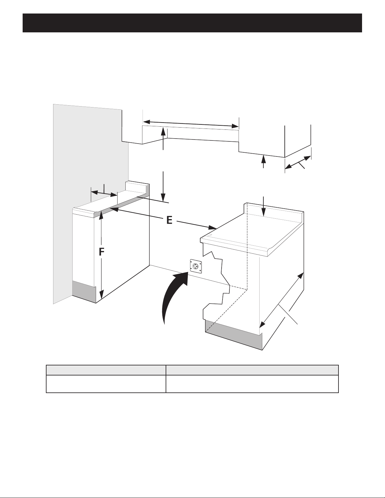
Cabinet Dimensions
Clearances and Dimensions
• Provide adequate clearances between the appliance and adjacent combustible surfaces.
• Location - Check location where the appliance will be installed. Check for proper electrical supply and oor
stability.
• Dimensions shown must be used. Given dimensions provide minimum clearance. Contact surface must be
solid and level.
40 1/8" Min.
(101.9 cm)
1" (2.5 cm) min
to wall or vertical
surface above
36" (91.4 cm)
30" Min.**
(76.2 cm Min.)
Grounded
Wall Outlet
18" Min.
(45.7 cm Min.)
13" Max.
(33 cm Max.)
24" Min.
(61 cm Min.)
24½" max.
(62.2 cm Max.)
Figure 2: Cabinet Dimensions
E. MINIMUM CUTOUT WIDTH F. HEIGHT OF COUNTERTOP
40 1/4" (102.2 cm)
36" (91.4 cm) standard
35 7/8" (91.1 cm) minimum
NOTES:
1. Do not seal the range to the side cabinets.
2. 30" (76,2 cm) minimum clearance when the cabinet is unprotected.
* * 24" (61 cm) minimum clearance between the cooktop and the bottom of the cabinet when the bottom of
wood or metal cabinet is protected by not less than ¼" (0,64 cm) ame retardant millboard covered with not
less than No. 28 MSG sheet metal, 0,015" (0,4 mm) stainless steel, 0,024" (0,6 mm) aluminum, or 0,020"
(0,5 mm) copper.
3. 0" clearance between range and cabinets or vertical surfaces that are below the cooktop height.
4. 0" clearance between range back and rear wall or cabinet.
5
Page 6
40" ELECTRIC RANGE INSTALLATION INSTRUCTIONS
1.
Electrical Requirements
Electrical Shock Hazard –Electrical ground is
required on this appliance. Use only the power cord
supplied with the appliance. Improper connections and
grounding may result in electric shock, damage to the
appliance, personal injury, re or death.
Grounding Requirements
This appliance must be installed and grounded by a
qualied technician.
In the United States, install in accordance with the National
Fuel Gas Code ANSI Z223.1/NPFA No. 54, latest edition
and National Electrical Code NFPA No. 70 latest edition,
and local electrical code requirements. In Canada, install in
accordance with CAN/CGA B149.1 and CAN/CGA B149.2
and CSA Standard C22.1, Canadian Electrical code, Part
1-latest editions and local electrical code requirements.
For personal safety, this appliance must be properly
grounded. For maximum safety, the power cord must
be plugged into an electrical outlet that is the correct
voltage, is correctly polarized and properly grounded
in accordance with local codes. It is the personal
responsibility of the consumer to have the appropriate
outlet with the correct, properly grounded wall receptacle
installed by a qualied electrician.
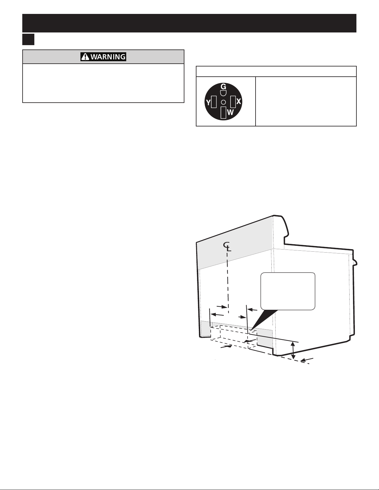
This appliance is intended to be plugged into a 14-50R
standard wall receptacle.
Electrical Wall Receptacle
Required for all installations
4-Wire receptacle (14-50R)
When only 4-wire, single phase, 240 volt, 60 Hz, AConly electrical supply is available, this appliance requires
minimum 40 amp circuit protection fused on both sides of
the line.
A time-delay circuit breaker or fuse is recommended.
Be sure the wall receptacle is within reach of the
appliance's nal installed location.
Do not pinch the power supply cord between the range
and the wall.
Recommended
wall outlet
installation
13"
(33 cm)
26"
(66 cm)
4 3/4"
(12 cm)
Figure 3: Recommended wall outlet installation area
area
7"
(17.8 cm)
Wall edge
6
Page 7
40" ELECTRIC RANGE INSTALLATION INSTRUCTIONS
Follow instructions for
the type of installation you have
Center
Line of
Range
Power Supply Cord
2.
Electrical Shock Hazard –Do not attempt to install
the appliance directly to a junction box, modify the
factory-installed cord, or connect a different power
cord to the appliance. If the wall outlet is not sufcient
to support the requirements of this appliance, it is the
responsibility of the consumer to have the appropriate
outlet installed by an electrician. Improper installation
and electrical connections can result in electric shock,
damage to the appliance, personal injury, re, or death.
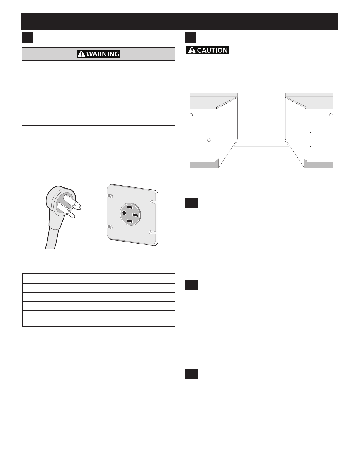
This appliance is equipped with a factory-connected,
4-wire power supply cord (Figure 4). This cord is rated
at 240 volts, 40 amps, and temperature rated at 194°F
(90°C). This cord is UL/CSA listed and has been tested
and approved for use with this appliance.
Figure 4: Factory connected power supply cord
Appliance Rating* Power Supply Rating
120/240 Volts 120/208 Volts Amps Temp Rating
8.8-16.5 kW 7.8-12.5 kW 40 or 50 194°F (90°C)
16.6-22.5 kW 12.6-18.5 kW 50 194°F (90°C)
* The NEC calculated load is less than the total connec-
ted load listed on the serial plate.
3.
Cabinet Construction
To eliminate the risk of burns or re by
reaching over heated surface units, do not have cabinet
storage space above the range. If there is cabinet storage
space above range, reduce risk by installing a range
hood that projects horizontally a minimum of 5" (12,7 cm)
beyond the bottom of the cabinet.
Figure 5: Cabinet construction
3.1
Installation: Cabinet on Both Sides
1. If range will be installed with a cabinet on both sides,
Draw a center line on the oor between the cabinets
(Figure 5).
2. If back of range will not be ush with the wall (the
location of the outlet may not allow the range to be
positioned against the wall), draw a line on the oor
where the back edge of the range will be.
3. Install anti-tip brackets (see "Anti-Tip Bracket
Installation").
3.2
Installation: Cabinet on One Side Only
1. If range will be installed with a cabinet on one side
only, move the range into nal position.
2. Draw a line on the oor along the side of the range
that is not against the cabinet. If back of range will
not be ush with the wall (the location of the outlet
may not allow the range to be positioned against the
wall), draw a line on the oor where the back edge of
the range will be.
3. Install anti-tip brackets (see "Anti-Tip Bracket
Installation").
3.3
Installation: Without Cabinet
1. If range will not be installed against a cabinet, move
range into nal position.
2. Mark on the oor along both sides of the range.
If back of range will not be ush with the wall (the
location of the outlet may not allow the range to be
positioned against the wall), draw a line on the oor
where the back edge of the range will be.
3. Install anti-tip brackets (see "Anti-Tip Bracket
Installation").
7
Page 8
40" ELECTRIC RANGE INSTALLATION INSTRUCTIONS
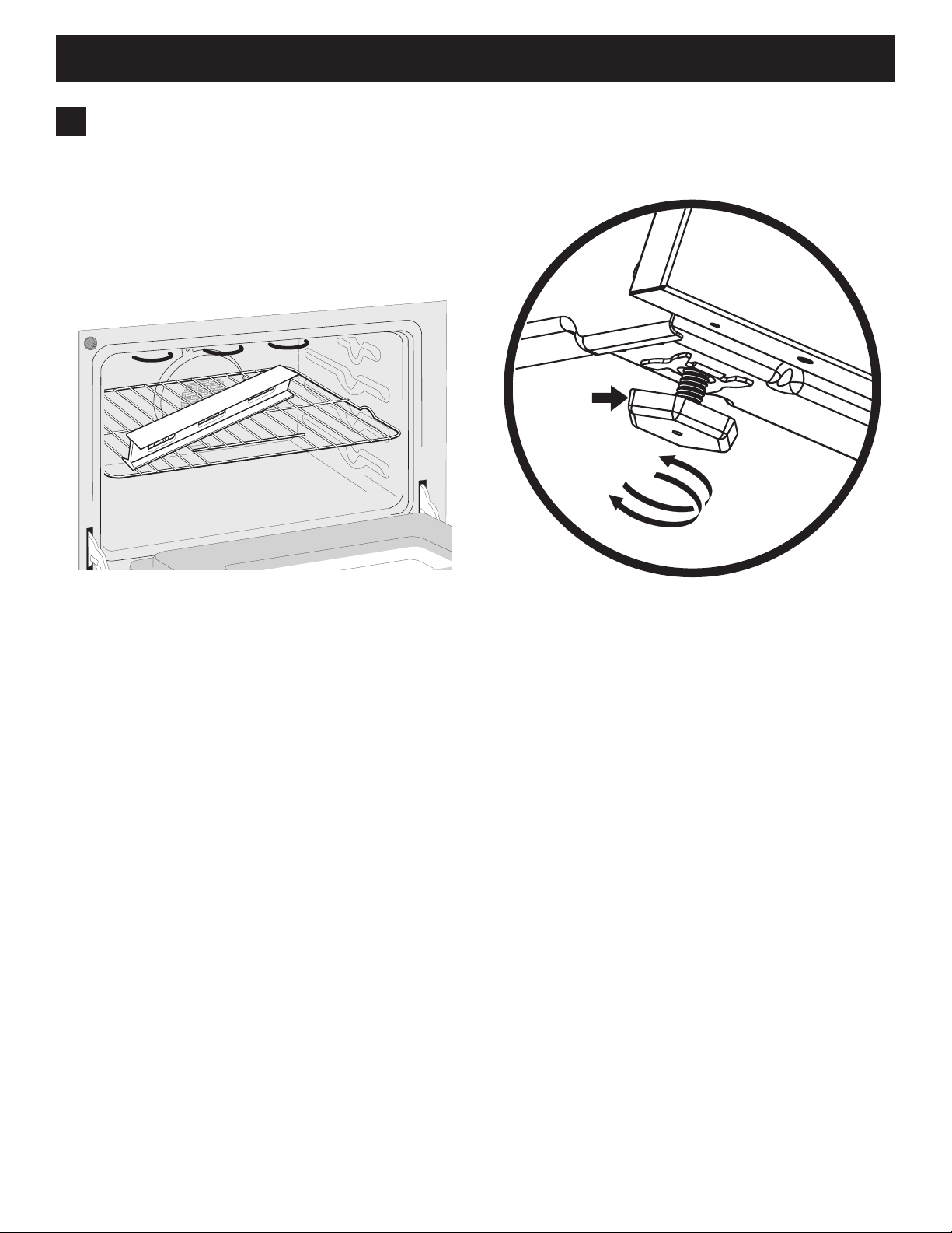
4.
Leveling the Range
Level the range and set cooktop height before
installation in the cut-out opening (if applicable).
1. Install an oven rack in the center of the oven.
2. Place a level on the rack (Figure 6). Take 2 readings
with the level placed diagonally in one direction and
then the other.
3. Level the range, if necessary, by adjusting the 4 leg
levelers with a wrench (Figure 7).
Leg
Leveler
Raise
Lower
Figure 6: Leveling the range
Figure 7: Adjusting appliance height
4. Slide range into cut-out opening and double check
for levelness. If the range is not level, pull unit out
and readjust leveling legs, or make sure oor is level.
8
Page 9

40" ELECTRIC RANGE INSTALLATION INSTRUCTIONS
5.
Anti-Tip Bracket Installation
To reduce the risk of tipping the appliance,
the appliance must be secured to the oor by the properly
installed anti-tip bracket and screws packed with the
range. These parts are located in the oven. Failure to
install the anti-tip bracket will allow the range to tip over if
excessive weight is placed on an open door or if a child
climbs on it. Serious injury might result from spilled hot
liquids or from the range itself.
If range is ever moved to a different location, the antitip brackets must also be moved and installed with the
range.
Tools Required:
• Adjustable Wrench
• Ratchet
• Drill & 1/8" (0,32 cm) bit
• 5/16" (0,8 cm) Nutdriver
• Level
Tip Over Hazard
• A child or adult can tip the range
and be killed.
• Verify the anti-tip device has been
installed to floor or wall.
• Ensure the anti-tip device is re-engaged to floor or wall
when the range is moved.
• Do not operate the range without the anti-tip device in
place and engaged.
• Failure to follow these instructions can result in death or
serious burns to children and adults.
Range
leveling leg
Anti-tip
bracket
5.1
Locate the Bracket Using the Template
Bracket may be located on either the left or right side of
the range. Mark the oor or wall where left or right side of
the range will be located.
Figure 8: Bracket template
If rear of range is against the wall or no further than 1-1/4”
from wall when installed, you may use the wall or oor
mount method. If molding is installed and does not allow
the bracket to t ush against the wall, remove molding or
mount bracket to the oor.
For wall mount, locate the bracket by placing the back
edge of the template against the rear wall and the side
edge of template on the mark made referencing the side
of the range. Place bracket on top of template and mark
location of the screw holes in wall.
If rear of range is further than 1-1/4” from the wall when
installed, attach bracket to the oor. For oor mount, locate
the bracket by placing back edge of the template where
the rear of the range will be located.
Mark the location of the screw holes shown in template.
To check if the anti-tip bracket is installed properly, use both
arms to grasp the rear edge of the range back. Carefully
attempt to tilt range forward. When properly installed, the range
should not tilt forward.
Refer to the anti-tip bracket installation instructions supplied
with your range for proper installation.
9
Page 10

40" ELECTRIC RANGE INSTALLATION INSTRUCTIONS
Leveling Leg
Anti-Tip Bracket
Floor Mount
5.2
Drill Pilot Holes and Fasten Bracket
Drill a 1/8” pilot hole where screws are to be located.
If bracket is to be mounted to the wall, drill pilot hole at
an approximate 20° downward angle. If bracket is to
be mounted to masonry or ceramic oors, drill a 3/16”
(4.8 mm) pilot hole 1-3/4” deep.
Figure 9: Drill pilot holes
The screws provided may be used in wood or concrete
material. Use a 5/16” nut-driver or at head screwdriver to
secure the bracket in place.
5.3
Check Level and Position the Range
Check the level of the nal installation. Note: A minimum
clearance of 1/8” is required between the bottom of the
range and the leveling leg to allow room for the bracket.
Use a spirit level to check your adjustments.
Figure 11: Leveling the range
Slide range into position.
1/8" Minimum
Wall Mount
Figure 10: Fastening the bracket
Wall Plate
3 5/16”
(84mm)
Figure 11: Slide appliance into bracket
To check if the anti-tip bracket is installed properly,
use both arms and grasp the rear edge of range back.
Carefully attempt to tilt range forward. When properly
installed, the range should not tilt forward.
If range is moved to a different location, the anti-tip
brackets must also be moved and installed with the range.
10
Page 11

40" ELECTRIC RANGE INSTALLATION INSTRUCTIONS
Check Operation
6.
Refer to the Use and Care Guide packaged with the
range for operating instructions and for care and
cleaning of your range.
Do not touch the elements. They may
be hot enough to cause burns.
Remove all packaging from the oven before testing.
6.1
Operation of Surface Elements
Turn on each of the four surface elements and check to
see that they heat. Check the surface element indicator
light(s), if equipped.
6.2
Operation of Oven Elements
The oven is equipped with an electronic oven control.
Each of the functions has been factory checked before
shipping. However, it is suggested that you verify the
operation of the electronic oven controls once more.
Refer to the Owner's Guide for operation. Follow the
instructions for the Clock, Timer, Bake, Broil, Convection
(some models) and Clean (some models) functions.
When All Hookups are Complete
Make sure all controls are left in the OFF position.
Model and Serial Number Location
The serial plate is located on top of the range's lower
front panel, and can be clearly viewed when the door is
open. When ordering parts for or making inquiries about
your range, have the model and serial numbers ready.
(Figure 13).
Bake–After setting the oven to 350°F (177°C) for baking,
the oor of the oven cavity should become warm.
Broil–When the oven is set to BROIL, the upper element
in the oven should become red.
Clean–When the oven is set for a self-cleaning cycle,
the upper element should become red during the preheat
portion of the cycle. After reaching the self-cleaning
temperature, the oor of the oven cavity should become
hot.
Convection–When the oven is set to CONV. BAKE/
ROAST at 350°F (177°C), both elements cycle on and
off alternately and the convection fan will turn. The
convection fan will stop turning when the oven door is
opened during convection baking or roasting.
Figure 13: Model, serial number location
Before You Call for Service
Read the Avoid Service Checklist and operating
instructions in your Owner's Guide. It may save you time
and expense. The list includes common occurrences that
are not the result of defective workmanship or materials
in this appliance.
Refer to the warranty and service information in your
Owner's Guide for our phone number and address.
Please call or write if you have inquiries about your
range product and/or need to order parts.
11
Page 12

40" ELECTRIC RANGE INSTALLATION INSTRUCTIONS
NOTES
12
Page 13

INSTRUCCIONES DE INSTALACIÓN DE COCINA ELÉCTRICA DE 40"
INSTRUCCIONES DE INSTALACIÓN
COCINA ELÉCTRICA DE 40"
LA INSTALACIÓN Y EL SERVICIO DEBEN SER REALIZADOS
POR UN INSTALADOR CALIFICADO.
IMPORTANTE: CONSERVE ESTAS INSTRUCCIONES PARA
USO DEL INSPECTOR LOCAL DE ELECTRICIDAD.
LEA Y CONSERVE ESTAS INSTRUCCIONES PARA REFERENCIA FUTURA.
Estados
Unidos
PARA SU SEGURIDAD: No guarde ni use gasolina u otros
vapores o líquidos inamables cerca de este o cualquier otro electrodoméstico.
Tabla de contenido
Instrucciones importantes para la seguridad ...........14-15
Dimensiones del producto ............................................ 16
Dimensiones del gabinete ............................................ 17
Requisitos eléctricos..................................................... 18
Cable eléctrico .............................................................. 19
Construcción del gabinete ............................................ 19
Aviso importante al consumidor
1. Conserve estas instrucciones con su guía del
propietario para referencia futura.
2. Cuando use cualquier electrodoméstico que genere
calor debe seguir precauciones de seguridad.
Estas precauciones se explican en el manual
de uso y cuidado. Lea atentamente el manual.
3. Asegúrese de que su electrodoméstico haya sido
correctamente instalado y puesto a tierra de forma
adecuada por un instalador calicado o un técnico
de servicio.
Nivelado de la cocina ................................................... 20
Instalación de los soportes antivuelco .....................21-22
Comprobación del funcionamiento ............................... 23
Ubicación de la placa de número de serie
(modelo y número de serie).......................................... 23
Notas ............................................................................ 24
Notas importantes para el instalador
1. Lea todas las indicaciones de estas instrucciones
de instalación antes de instalar la cocina.
2. Elimine todo el material de empacado del horno
y los compartimentos de cajones antes de conectar
la alimentación eléctrica a la cocina.
3. Es obligatorio instalar el soporte antivuelco
suministrado con el electrodoméstico.
4. Cumpla con todos los códigos y reglamentos aplicables.
5. Asegúrese de dejar estas instrucciones al consumidor.
Impreso en Estados Unidos
P/N 809018801 (1701) Rev.B
English – pages 1-12
Español – páginas 13-24
Français – pages 25-36
13
Page 14

INSTRUCCIONES DE INSTALACIÓN DE COCINA ELÉCTRICA DE 40"
INSTRUCCIONES DE SEGURIDAD IMPORTANTES
Este electrodoméstico debe haberse instalado y puesto a tierra
por un instalador calicado o un técnico de servicio.
Este manual contiene símbolos e instrucciones de seguridad importantes. Le rogamos que preste mucha atención
a estos símbolos y siga todas las instrucciones. No intente instalar o usar su electrodoméstico hasta haber leído
las precauciones de seguridad indicadas en este manual. Las indicaciones de seguridad presentes en este manual
están etiquetadas como "ADVERTENCIA" o "PRECAUCIÓN" de acuerdo con el nivel de riesgo.
Las advertencias e instrucciones importantes de esta guía no fueron pensadas para cubrir todas las condiciones y situaciones
posibles. Debe tener sentido común, tener cuidado y prestar atención al instalar, operar y mantener su electrodoméstico.
Este es el símbolo de las alertas de seguridad. Se usa para alertar sobre peligros potenciales de lesiones personales.
Obedezca todos los mensajes de seguridad que lleven este símbolo para evitar posibles lesiones o la muerte.
Indica una situación potencialmente peligrosa que, si no se evita, podría causar lesiones graves o la
muerte.
Indica una situación potencialmente peligrosa que, si no se evita, podría causar lesiones personales
leves o moderadas.
IMPORTANTE: Indica información importante, de instalación, de funcionamiento o de mantenimiento que no está
relacionada con situaciones de peligro.
WARNING:
Riesgo de volcamiento
• Un niño o adulto puede volcar la estufa y
acabar muerto.
• Verifique que se haya instalado el
dispositivo antivuelco en el piso o en la
pared.
• Asegúrese de que el dispositivo antivuelco se haya reacoplado
cuando mueva la estufa sobre el piso o a la pared.
• No utilice la estufa sin el dispositivo antivuelco instalado y
acoplado.
• Si no se siguen estas instrucciones, se puede provocar la muerte
o quemaduras graves en niños y adultos.
Tornillo
nivelador de
la estufa
Para verificar si el soporte antivuelco está instalado
correctamente, sostenga el borde trasero de la parte
trasera de la estufa usando ambos brazos. Intente inclinar
la estufa hacia adelante con cuidado. Si está instalada
correctamente, la estufa no debería inclinarse hacia
adelante.
Consulte las instrucciones de instalación del soporte
antivuelco proporcionadas con la estufa para instalarlo
adecuadamente.
Soporte
antivuelco
• Riesgo de peso excesivo: Para mover e instalar
la cocina se necesitan dos o más personas.
El incumplimiento de estas instrucciones puede
provocar lesiones en la espalda o de otro tipo.
• Almacenamiento dentro o sobre el
electrodoméstico: No deben almacenarse
materiales inamables dentro de un horno,
cerca de los quemadores o elementos superiores
o en el cajón almacenamiento o de calentar
(en su caso). Esto incluye artículos de papel,
plástico y tela, tales como libros de cocina, objetos
de plástico y toallas, así como líquidos inamables.
No guarde explosivos, como latas de productos
en aerosol, sobre o cerca del electrodoméstico.
• No deje a los niños solos: No se debe dejar
a los niños solos o sin vigilancia en el área donde
se usa el electrodoméstico. Nunca permita que
los niños se sienten o se paren sobre ninguna
pieza del electrodoméstico, incluyendo el cajón
de almacenamiento, el cajón asador inferior,
el cajón calentador o el horno doble inferior.
• No guarde artículos atractivos para los niños en los
gabinetes que estén arriba del electrodoméstico
o en el protector trasero. Si los niños se suben o
acercan al electrodoméstico para alcanzar dichos
artículos podrían sufrir lesiones graves.
• Pararse, apoyarse o sentarse sobre la puerta o los
cajones de este aparato puede causar lesiones
graves y, además, dañar el electrodoméstico.
• No utilice el horno ni el cajón de calentar
(en su caso) para almacenaje.
• Nunca utilice su electrodoméstico como calefactor
para calentar la habitación. Si lo hace puede
producirse una intoxicación por monóxido de carbono
y un sobrecalentamiento del electrodoméstico.
• No guarde ni use gasolina u otros vapores
o líquidos inamables cerca de este o cualquier
otro electrodoméstico.
14
Page 15

INSTRUCCIONES DE INSTALACIÓN DE COCINA ELÉCTRICA DE 40"
INSTRUCCIONES IMPORTANTES PARA
DESEMPACADO E INSTALACIÓN
Lea y siga las siguientes instrucciones y precauciones
a la hora de desempacar, instalar y realizar
el mantenimiento del electrodoméstico:
• Destruya la caja de cartón y las bolsas de plástico
después de desempacar el electrodoméstico.
Nunca deje que los niños jueguen con el material
de empaque. No retire la etiqueta del cableado y otras
indicaciones escritas adheridas al electrodoméstico.
No retire la placa de número de modelo/serie.
• Las temperaturas bajas pueden dañar el control
electrónico. Cuando use el electrodoméstico por
primera vez, o cuando este no se haya usado por
un período largo de tiempo, asegúrese de que la
unidad esté en temperaturas superiores a los 32°F
(0°C) durante al menos 3 horas antes de encenderla.
• No modique ni altere la construcción del
electrodoméstico a través de la extracción de los tornillos
niveladores, los paneles, los protectores de cables, los
tornillos o soportes antivuelco u otra pieza.
• Instalación adecuada: Asegúrese de que su
electrodoméstico haya sido correctamente instalado
y puesto a tierra por un técnico calicado. En Estados
Unidos, debe instalarse de acuerdo con el Código
Nacional de Gas Combustible ANSI Z223.1/NPFA
No. 54, última edición y el Código eléctrico Nacional
NFPA No. 70 última edición, además de los requisitos
normativos locales. En Canadá este electrodoméstico
debe instalarse según CAN/CGA B149.1 y CAN/CGA
B149.2 y la norma CSA Estándar C22.1 del Código
Canadiense de Electricidad (Canadian Electrical Code),
Parte 1, últimas ediciones, y los códigos eléctricos
locales. Instale siguiendo solamente las instrucciones
de instalación proporcionadas en la documentación
de este electrodoméstico.
• La instalación de electrodomésticos diseñados
para su instalación en viviendas manufacturadas
(móviles) debe cumplir la Norma sobre construcción
y seguridad de viviendas manufacturadas, título
24CFR, parte 3280 [Anteriormente Norma Federal
sobre construcción y seguridad de viviendas móviles,
título 24, HUD (parte 280)] o bien, en los casos
en los que no sea aplicable esta Norma, la Norma
para la instalación de viviendas manufacturadas
1982 (Manufactured Home Sites, Communities and
Setups), ANSI Z225.1/NFPA 501A-última edición,
o bien cumplir los códigos locales en Estados Unidos
y CAN/CSA-Z240 MH en Canadá.
• Antes de instalar una cocina en una zona cubierta con
linóleo o cualquier otro tipo de revestimiento sintético
del piso, asegúrese de que el revestimiento resiste
al menos 90°F (32,2°C) por encima de la temperatura
ambiente sin encogerse, deformarse ni decolorarse.
No instale la cocina sobre alfombras o moquetas
salvo que incluya una almohadilla u hoja aislante
de contrachapado de ¼" (0,64 cm) de espesor
entre la cocina y el alfombrado.
• Asegúrese de que todos los revestimientos de los
muros y materiales de los gabinetes cercanos
a la cocina pueden resistir el calor que genera
el electrodoméstico.
• Para eliminar el riesgo de quemaduras o incendios
en movimientos por encima de la supercie caliente
de las unidades, debe evitarse el espacio de
almacenamiento en gabinetes sobre la supercie.
Si va a incluirse almacenamiento en gabinete,
puede reducirse al riesgo instalando una campana
extractora que sobresalga horizontalmente un mínimo
de 5 pulgadas más allá de la base del gabinete.
• No obstruya el ujo de aire de la ventilación del horno,
alrededor de la base o bajo el panel frontal inferior del
electrodoméstico. Este electrodoméstico necesita aire
fresco para un funcionamiento correcto.
• Asegúrese de que haya un extintor de espuma
adecuado disponible, ubicado de manera visible
y fácilmente accesible cerca del electrodoméstico.
INSTRUCCIONES IMPORTANTES PARA SERVICIO
Y MANTENIMIENTO
• No repare ni reemplace ninguna pieza del
electrodoméstico a menos que se recomiende
especícamente en los manuales. Las reparaciones
adicionales deben ser realizadas por un técnico
calicado. Esto reduce el riesgo de lesiones
personales y daños al electrodoméstico.
• Contacte siempre a su dealer, distribuidor,
agente de servicio o fabricante sobre los problemas
o situaciones que no comprenda.
• Consulte con su distribuidor para que le recomiende
un técnico calicado y un centro de servicio
autorizado. Aprenda a desconectar la energía
eléctrica del electrodoméstico en el disyuntor
o en la caja de fusibles en caso de una emergencia.
• Saque la puerta del horno de todo electrodoméstico
que ya no se utilice cuando lo guarde o lo descarte.
• No toque una bombilla caliente del horno con un paño
húmedo. Esto puede hacer que la bombilla se rompa.
Manipule las luces halógenas (en su caso) con toallas
de papel o guantes suaves. Desconecte o apague el
electrodoméstico antes de sacar y sustituir la bombilla.
15
Page 16

INSTRUCCIONES DE INSTALACIÓN DE COCINA ELÉCTRICA DE 40"
Dimensiones del producto
No instale la unidad en el gabinete antes de leer las dos páginas siguientes.
B
C
A
37"
(94 cm)
patas ex-
tendidas
A. ALTO B. ANCHO
49" (124,5 cm) 40" (101,6 cm)
Figura 1: Dimensiones del producto
C. FONDO HASTA LA PARTE
FRONTAL DE LA COCINA
26 1/16" (66,2 cm)
28 1/2" (72,4 cm) máx con la manija
16
D
D. FONDO CON
LA PUERTA ABIERTA
47 3/4" (121.3 cm)
Page 17

INSTRUCCIONES DE INSTALACIÓN DE COCINA ELÉCTRICA DE 40"
Dimensiones del gabinete
Distancias y dimensiones
• Deje suciente espacio entre el electrodoméstico y las supercies combustibles adyacentes.
• Ubicación: Compruebe la ubicación donde vaya a instalarse el electrodoméstico. Compruebe el suministro
eléctrico adecuado y la estabilidad del piso.
• Deben utilizarse las dimensiones mostradas. Las dimensiones dadas ofrecen la distancia mínima.
La supercie de contacto debe ser sólida y nivelada.
40 1/8" Mín.
(101,9 cm)
1" (2,5 cm) mín
hasta el muro o supercie
vertical por encima
36" (91,4 cm)
30" Mín.**
(76,2 cm Mín.)
Toma mural
puesta a tierra
18" Mín.
(45,7 cm Mín.)
13" Máx.
(33 cm Máx.)
24" Mín.
(61 cm Mín.)
24½" máx.
(62,2 cm Máx.)
Figura 2: Dimensiones del gabinete
E. PROFUNDIDAD DE CORTE MÍNIMA F. ALTURA DE LA ENCIMERA
40 1/4" (102,2 cm)
36" (91,4 cm) estándar
35 7/8" (91,1 cm) mínimo
NOTAS:
1. No selle la cocina a los gabinetes laterales.
2. 30" (76,2 cm) de distancia mínima si el gabinete no está protegido.
* * 24" (61 cm) de distancia mínima entre la supercie de cocción y la parte inferior del gabinete
si la base de madera o metálica del gabinete tiene una protección superior igual a ¼" (0,64 cm)
de retardante de llamas tipo Millboard recubierto con al menos una chapa metálica MSG No. 28,
0,015" (0,4 mm) de acero inoxidable, 0,024" (0,6 mm) de aluminio o 0,020" (0,5 mm) de cobre.
3. 0" de espacio entre la cocina y los gabinetes o supercies verticales situadas por debajo de la altura
de la supercie de cocción.
4. 0" de espacio entre la parte trasera de la cocina y los gabinetes o muro traseros.
17
Page 18

INSTRUCCIONES DE INSTALACIÓN DE COCINA ELÉCTRICA DE 40"
1.
Requisitos eléctricos
Este electrodoméstico está hecho para conectarse
a una toma mural estándar 14-50R.
Riesgo de choque eléctrico: Este electrodoméstico
necesita una puesta a tierra eléctrica. Utilice solo
el cable eléctrico suministrado con el electrodoméstico.
Unas conexiones y una puesta a tierra incorrectas
pueden provocar descargas eléctrico as, daños
al electrodoméstico, lesiones personales,
incendios o la muerte.
Requisitos de puesta a tierra
Este electrodoméstico debe haberse instalado y puesto
a tierra por un técnico calicado.
En Estados Unidos, debe instalarse de acuerdo con el
Código Nacional de Gas Combustible ANSI Z223.1/NPFA
No. 54, última edición y el Código eléctrico Nacional
NFPA No. 70 última edición, además de los requisitos
normativos locales. En Canadá este electrodoméstico debe
instalarse según CAN/CGA B149.1 y CAN/CGA B149.2
y la norma CSA Estándar C22.1 del Código Canadiense
de Electricidad (Canadian Electrical Code), Parte 1,
últimas ediciones, y los códigos eléctricos locales.
Para su seguridad personal, este electrodoméstico debe
estar debidamente puesto a tierra. Para una máxima
seguridad, el cable de alimentación debe estar enchufado
a un tomacorriente del voltaje adecuado, que esté
correctamente polarizado y debidamente puesto a tierra
de acuerdo con los códigos locales. Es la responsabilidad
personal del consumidor hacer que un electricista
calicado instale un tomacorriente adecuado con
un receptáculo de pared debidamente puesto a tierra.
Cuando solo haya disponible un suministro eléctrico
de 4 conductores, monofásico, de 240 voltios, 60 Hz y AC,
este aparato requiere una protección mínima de circuito
de 40 amp con fusibles en ambos lados de la línea.
Se recomienda un interruptor disyuntor o un fusible
retardado.
Asegúrese de que la toma mural sea accesible con
la posición nal de instalación del electrodoméstico.
No pince el cable eléctrico entre la cocina y el muro.
(66 cm)
Toma eléctrica mural
Toma de 4 conductores (14-50R)
13"
(33 cm)
26"
de la toma mural
Obligatorio para todas
las instalaciones
Área
recomendada
de instalación
7"
(17,8 cm)
18
4 3/4"
(12 cm)
Borde
de pared
Figura 3: Área recomendada
de instalación de la toma mural
Page 19

INSTRUCCIONES DE INSTALACIÓN DE COCINA ELÉCTRICA DE 40"
Cable eléctrico
2.
Riesgo de choque eléctrico: No intente instalar
el electrodoméstico directamente en una caja de
conexiones, modicar el cable instalado de fábrica
o conectar un cable diferente al electrodoméstico.
Si la toma eléctrica no basta para soportar las exigencias
de este electrodoméstico, es responsabilidad del
consumidor hacer que un electricista calicado instale
un tomacorriente adecuado. Una instalación y unas
conexiones eléctricas incorrectas pueden provocar
descargas eléctrico as, daños al electrodoméstico,
lesiones personales, incendios o la muerte.
Este electrodoméstico está equipado con un cable
eléctrico de 4 conductores conectado en la fábrica
(Figura 4). Este cable tiene una capacidad nominal de
240 voltios, 40 amperios y una temperatura de 194°F
(90°C). Este cable es conforme con UL/CSA y se
ha comprobado y aprobado para usarse con este
electrodoméstico.
3.
Construcción del gabinete
Para eliminar el riesgo de quemaduras o
incendios en movimientos por encima de la
supercie caliente de las unidades, debe evitarse
el almacenamiento en gabinetes sobre la cocina.
Si hay espacio de almacenamiento en gabinetes por
encima de la cocina, reduzca el riesgo instalando una
campana extractora que sobresalga horizontalmente un
mínimo de 5" (12,7 cm) más allá de la base del gabinete.
Línea de centro
de la cocina
Siga las instrucciones para
el tipo de instalación que tiene
Figura 5: Construcción del gabinete
Figura 4: Cable eléctrico conectado en la fábrica
Valores nominales
del electrodoméstico*
120/240
voltios
8,8-16,5 kW 7,8-12,5 kW 40 o 50 194°F (90°C)
16,6-22,5 kW 12,6-18,5 kW 50 194°F (90°C)
* La carga NEC calculada es inferior a la carga conectada
total indicada en la placa de serie.
120/208
voltios
Alimentación
eléctrica nominal
Amps Valor de
temperatura
3.1
Instalación: Gabinete a ambos lados
1. Si la cocina va a instalarse con un gabinete a ambos
lados, dibuje la línea central en el piso entre los dos
gabinetes (Figura 5).
2. Si la parte trasera de la cocina no va a quedar junto
al muro (la ubicación de la toma puede no permitir la
ubicación de la cocina contra el muro), dibuje una línea
en el piso donde estará el borde trasero de la cocina.
3. Instale soportes antivuelco (consulte "Instalación
del soporte antivuelco").
3.2
Instalación: Gabinete solo a un lado
1. Si la cocina va a instalarse con un gabinete a un lado
solamente, coloque la cocina en su posición nal.
2. Dibuje una línea en el piso a lo largo del costado
de la cocina que no queda contra el gabinete. Si la
parte trasera de la cocina no va a quedar junto al muro
(la ubicación de la toma puede no permitir la ubicación
de la cocina contra el muro), dibuje una línea en
el piso donde estará el borde trasero de la cocina.
3. Instale soportes antivuelco (consulte "Instalación
del soporte antivuelco").
3.3
Instalación: Sin gabinete
1. Si la cocina no se va a instalar contra un gabinete,
coloque la cocina en su posición nal.
2. Marque en el piso a lo largo de ambos lados de
la cocina. Si la parte trasera de la cocina no va
a quedar junto al muro (la ubicación de la toma
puede no permitir la ubicación de la cocina contra
el muro), dibuje una línea en el piso donde estará
el borde trasero de la cocina.
3. Instale soportes antivuelco (consulte "Instalación
19
del soporte antivuelco").
Page 20

INSTRUCCIONES DE INSTALACIÓN DE COCINA ELÉCTRICA DE 40"
4.
Nivelado de la cocina
Nivele la cocina y ajuste la altura de la supercie de
cocción antes de instalar en la abertura recortada
(en su caso).
1. Coloque una parrilla en el centro del horno.
2. Coloque un nivel en la parrilla (Figura 6). Realice 2
lecturas con el nivel colocado en diagonal, primero
en una dirección y luego en la otra.
3. Nivele la cocina, si es necesario, ajustando los 4
niveladores de las patas con una llave (Figura 7).
Pata
Niveladora
Levantar
Descender
Figura 6: Nivelado de la cocina
Figura 7: Ajuste de la altura del electrodoméstico
4. Deslice la cocina en la abertura recortada y verique
que está nivelada. Si la cocina no está nivelada,
extraiga la unidad y reajuste las patas de nivelado,
o asegúrese de que el suelo esté nivelado.
20
Page 21

INSTRUCCIONES DE INSTALACIÓN DE COCINA ELÉCTRICA DE 40"
5.
Instalación del soporte antivuelco
Para reducir el riesgo de vuelco del
electrodoméstico, debe jarse al piso con el soporte
antivuelco y los tornillos incluidos con la cocina
debidamente instalados. Estas piezas se encuentran
en el horno. Si no instalará el soporte antivuelco, la cocina
puede volcarse en caso de que se le aplique un peso
excesivo a la puerta abierta o si un niño se sube a ella.
El derrame de líquidos calientes o la propia cocina pueden
provocar lesiones de gravedad.
Si se traslada la cocina a una ubicación diferente,
los soportes antivuelco también deben trasladarse
e instalarse con la cocina.
Herramientas necesarias:
• Llave inglesa
• Trinquete
• Taladradora con broca de 1/8" (0,32 cm)
• Llave para tuercas de 5/16" (0,8 cm)
• Nivel
WARNING:
Riesgo de volcamiento
• Un niño o adulto puede volcar la estufa y
acabar muerto.
• Verifique que se haya instalado el
dispositivo antivuelco en el piso o en la
pared.
• Asegúrese de que el dispositivo antivuelco se haya reacoplado
cuando mueva la estufa sobre el piso o a la pared.
• No utilice la estufa sin el dispositivo antivuelco instalado y
acoplado.
• Si no se siguen estas instrucciones, se puede provocar la muerte
o quemaduras graves en niños y adultos.
Tornillo
nivelador de
la estufa
Soporte
antivuelco
5.1
Localice el soporte usando la plantilla
El soporte puede situarse en en el lado izquierdo o derecho
de la cocina. Marque en el piso o la pared en lugar donde
se encontrará el lado izquierdo o derecho de la cocina.
Figura 8: Plantilla para el soporte
Si la parte trasera de la cocina está contra un muro
o a no más de 1-1/4” de un muro tras la instalación,
puede utilizar el método de montaje en el piso o en un
muro. Si hay alguna moldura decorativa instalada que
no permite el encaje del soporte contra la pared, retire
la moldura o monte el soporte sobre el piso.
Para montaje en la pared, localice el soporte situando
el borde trasero de la plantilla contra el muro trasero
y el lado de la plantilla en la marca de referencia del lado
de la cocina. Sitúe el soporte sobre la plantilla y marque
la ubicación de los oricios en el muro.
Si la parte trasera de la cocina está a más de 1-1/4” de un
muro tras la instalación, je el soporte al piso. Para montaje
en el piso, localice el soporte situando el borde trasero
de la plantilla donde estará la parte trasera de la cocina.
Marque la ubicación de los oricios indicados en la plantilla.
Para verificar si el soporte antivuelco está instalado
correctamente, sostenga el borde trasero de la parte
trasera de la estufa usando ambos brazos. Intente inclinar
la estufa hacia adelante con cuidado. Si está instalada
correctamente, la estufa no debería inclinarse hacia
adelante.
Consulte las instrucciones de instalación del soporte
antivuelco proporcionadas con la estufa para instalarlo
adecuadamente.
21
Page 22

INSTRUCCIONES DE INSTALACIÓN DE COCINA ELÉCTRICA DE 40"
Soporte de nivelación
Soporte antivuelco
5.2
Perfore los oricios guía y je el soporte
Perfore un oricio guía de 1/8” donde deban situarse los
tornillos. Si el soporte va a jarse al muro, el oricio guía
debe tener un ángulo aproximado de 20° hacia abajo.
Si el soporte va a montarse en mampostería o pisos
cerámicos, perfore un oricio guía de 3/16” (4,8 mm)
y 1-3/4” de profundidad.
SOPORTE
ANTIVUELCO
Figura 9: Perfore los oricios guía
Los tornillos suministrados pueden utilizarse en materiales
como madera o concreto. Utilice una llave para tuercas
de 5/16” o un destornillador de punta plana para jar
el soporte en su lugar.
5.3
Compruebe el nivelado y la posición
de la cocina
Compruebe el nivelado de la instalación nal.
Nota: Es necesario un espacio mínimo de 1/8” entre
la parte inferior de la cocina y la pata de nivelado para
dejar espacio para el soporte. Utilice un nivel de burbuja
para comprobar los ajustes.
Figura 11: Nivelado de la cocina
Montaje en piso
1/8" Mínimo
Figura 10: Fijación del soporte
Montaje
en muro
Placa del
muro
Deslice la cocina hasta su posición.
3 5/16”
(84mm)
Lado de
la cocina
Figura 11: Deslice el electrodoméstico en el soporte
Para comprobar si el soporte antivuelco se ha instalado
correctamente, sostenga con ambas manos el borde
trasero de la parte trasera de estufa. Con cuidado, trate
de inclinar la estufa hacia delante. Si está correctamente
instalada, la estufa no se inclinará hacia delante.
Si se traslada la cocina a una ubicación diferente, los
soportes antivuelco también deben trasladarse e instalarse
con la cocina.
22
Page 23

INSTRUCCIONES DE INSTALACIÓN DE COCINA ELÉCTRICA DE 40"
Comprobación del funcionamiento
6.
Consulte las instrucciones de uso y de cuidado y limpieza
de la cocina en el manual de uso y cuidado incluido.
Cuando todas las conexiones están completas
Asegúrese de que todos los controles se encuentran
en la posición OFF.
No toque los elementos. Pueden estar lo
sucientemente calientes como para provocar quemaduras.
Quite todo el material de empaque del horno antes
de probarlo.
6.1
Uso de los elementos de supercie
Active cada uno de los cuatro elementos de supercie
y verique que calientan. Compruebe las luces
indicadoras de los elementos de supercie, en su caso.
6.2
Uso de los elementos del horno
El horno está equipado con un control electrónico.
Todas las funciones se han comprobado en fábrica antes
del envío. No obstante, recomendamos que verique
una vez más la operación de los controles electrónicos
del horno. Consulte la operación en el manual del
propietario. Siga las instrucciones para las funciones
de reloj, temporizador, horneado, rostizado, convección
(algunos modelos) y limpieza (algunos modelos).
Horneado: Tras ajustar el horno en 350°F (177°C) para
hornear, el piso de la cavidad debe calentarse.
Ubicación del número de modelo y de serie
La placa de serie se encuentra en la parte superior
del panel frontal inferior de la cocina y puede verse
claramente con la puerta abierta. Cuando llame para
pedir partes o hacer consultas sobre su cocina, tenga
preparados los números de modelo y de serie. (Figura 13).
Rostizado: Cuando el horno se ajusta en BROIL,
el elemento superior del horno debe cambiar a rojo.
Limpieza: Cuando se programa un ciclo de auto
limpieza del horno, el elemento superior debe cambiar
a rojo durante la fase de precalentamiento del
ciclo. Tras alcanzar la temperatura de autolimpieza,
el piso de la cavidad del horno debe calentarse.
Convección: Cuando el horno se ajusta en CONV.
BAKE/ROAST a 350°F (177°C), ambos elementos
se encienden y apagan alternativamente y el ventilador
de convección gira. El ventilador de convección
deja de girar al abrir la puerta durante el horneado
o rostizado por convección.
Figura 13: Ubicación del número de modelo y de serie
Antes de solicitar asistencia técnica
Lea la lista de comprobación previa a la llamada
a la asistencia técnica y las instrucciones de operación
de su manual del propietario. Puede ahorrarle tiempo
y dinero. La lista incluye situaciones comunes que
no son el resultado de mano de obra o materiales
defectuosos en este electrodoméstico.
Consulte en la información de garantía y servicio
del manual del propietario nuestro número de teléfono
y dirección. Llame o escriba si tiene alguna consulta
sobre su cocina y/o necesita solicitar alguna parte.
23
Page 24

INSTRUCCIONES DE INSTALACIÓN DE COCINA ELÉCTRICA DE 40"
NOTAS
24
 Loading...