

Kenmore Elite 79078902000, 79078902001, 79078902002, 79078903000, 79078903001 Installation Guide
...Page 1
iNSTALLATiON AND SERVICE MUST BE PERFORMED BY A QUALiFiED iNSTALLER.
iMPORTANT: SAVE FOR LOCAL ELECTRICAL iNSPECTOR'S USE.
READ AND SAVE THESE iNSTRUCTiONS FOR FUTURE REFERENCE.
FOR YOUR SAFETY: Do not store or use gasollne or other flammable vapors and liquids
in the vicinity of fhls or any other appliance.
_f the informationin thismanual is not followed exactly, a _re
or explosion may result causing property damage, petsona_ injury or death.
FOR YOUR SAFETY:
m Do not store or use gasoline or other flammable vapors and liquids
in the vicinity of fhls or any other appliance.
WHAT TO DO iF YOU SMELL GAS:
* Do nat fry to light any appliance.
* Do nat touch any elec|rlcal switch; do not use any phone in your
building.
" Immedlately call your gas supplier from a neighbor's phone. Fellow
the gas suppller's instructions.
* If you cannot reach your gas supplier, call the fire department.
Insfallaflan and service must be performed by a quallfled installer,
service agency or the gas supplier.
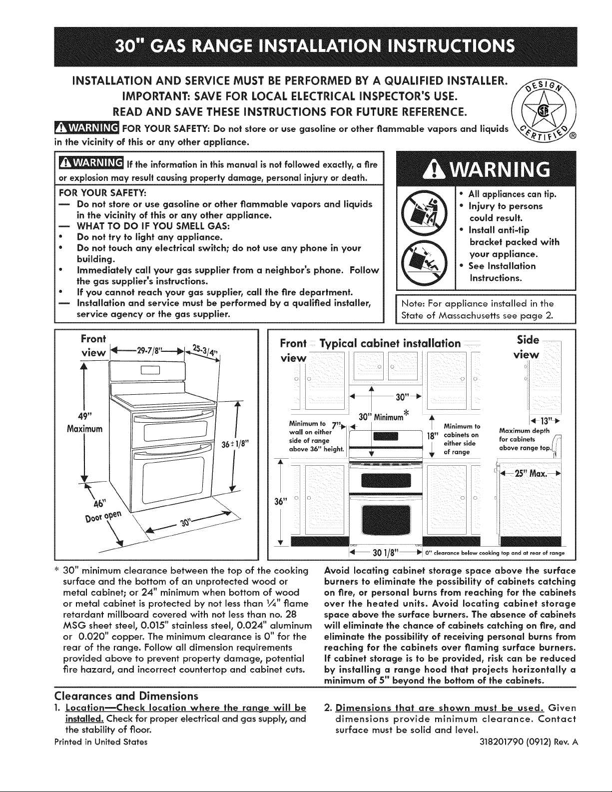
Front
view
Note: For appliance installed in the
State of Massachusetts see page 2.
49"
Maximum
36t 1/8"
/
A_
30" minimum clearance between the top of the cooking
surface and the bottom of an unprotected wood or
metal cabinet; or 24" minimum when bottom of wood
or metal cabinet is protected by not less than 1/_" flame
retardant millboard covered with not less than no. 28
MSG sheet steel, 0.015" stainless steel, 0.024" aluminum
or 0.020" copper. The minimum clearance is 0" for the
rear of the range. Follow all dimension requirements
provided above to prevent property damage, potential
fire hazard, and incorrect countertop and cabinet cuts.
Clearances and Dimensions
1. Locatlon_Check Iocatlon where the range will be
installed. Check for proper electrical and gas supply, and
the stability of floor.
Printed in United States
,\
Avoid Iocatlng cabinet storage space above the surface
burners to eliminate the possibility of cabinets catching
on fire, or personal burns from reaching for the cabinets
over the heated units. Avoid Iocaflng cabinet storage
space above the surface burners. The absence of cabinets
will eliminate the chance of cabinets catching on rite, and
eliminate the possibility of receiving personal burns from
reaching for the cabinets over flaming surface burners.
if cabinet storage is to be provided, risk can be reduced
by insfalllng a range hood that projects horizontally a
minimum of 5" beyond the bottom of the cabinets.
2. Dimensions that are shown must be used. Given
dimensions provide minimum clearance. Contact
surface must be solid and level.
318201790 (0912) Rev.A
Page 2
important Notes to the installer
1. Read all instructions contained in these installation
instructions before installing the appliance.
2. Remove all packing material before connecting the
electrical supply to the appliance.
3. Observe all governing codes and ordinances.
4. Be sure to leave these instructions with the consumer.
5. Note: For operation at 2000 ft. elevations above sea
level, appliance rating shall be reduced by 4 percent
for each additional 1000 ft.
important Note to the Consumer
Keep these instructionswith your Use and Care Guide
for future reference.
IMPORTANT SAFETY INSTRUCTIONS
Installation of this range must conform with local codes
or, in the absence of local codes, with the National Fuel
Gas Code ANSI Z223.1/NFPA .54-latest edition.
When installed in a manufactured (mobile) home,
installation must conform with the Manufactured Home
Construction and Safety Standard, Title 24 CFRR, Part
3280 [formerly the Federal Standard for Mobile Home
Construction and Safety, Title 24, HUD (Part 280)] or,
when such standard is not applicable, the Standard
for Manufactured Home Installations, ANSI/NCSBCS
A.225.], or with local codes.
This range has been design certified by CSA
International. As with any appliance using gas and
generating heat, there are certain safety precautions
you should follow. You will find them in the Use and
Care Guide, read it carefully.
* Be sure your range is installed and grounded properly
by a qualified installer or service technician.
* This range must be electrically grounded in accordance
with local codes or, in their absence, wlfh the National
Electrical Code ANSI/NFPA No. 70--latest edition. See
Grounding Instructions in the Electrical Requirements
section of these Installation Instructions.
* Before installing the range in an area covered with
linoleum or any other synthetic floor covering, make
sure the floor covering can withstand heat at least 90°F
above room temperature without shrinking, warping or
discoloring. Do not install the range over carpeting unless
you place an insulating pad or sheet of 1/4" (10,]6cm)
thick plywood between the range and carpeting.
* Make sure the wall coverings around the range can
withstand the heat generated by the range.
Do not obstruct the flow of combustion air at the oven
vent nor around the base or beneath the lower front
panel of the range. Avoid touching the vent openings or
nearby surfaces as they may become hot while the oven
is in operation. This range requires fresh air for proper
burner combustion.
Air curtains or other overhead range hoods, which
operate by blowing a downward air flow onto a range,
shall not be used in conjunction with gas ranges other
than when the hood and range have been designed,
tested and listed by an independent test laboratory for
use in combination with each other.
Never leave children alone or unattended
in the area where an appliance is in use. As children grow,
teach them the proper, safe use of all appliances. Never
leave the oven door open when the range is unattended.
Stepping, leaning or sitting on the doors
or drawers of this range can result in serious injuries and
can also cause damage to the range.
Do not store items of interest to children in the cabinets
above the range. Children could be seriously burned
climbing on the range to reach items.
To eliminate the need to reach over the surface burners,
cabinet storage space above the burners should be
avoided.
Adjust surface burner flame size so it does not extend
beyond the edge of the cooking utensil. Excessive flame
is hazardous.
Do not use the oven as a storage space. This creates a
potentially hazardous situation.
Never use your range for warming or heating the room.
Prolonged use of the range without adequate ventilation
can be dangerous.
* Do not store or use gasoline or other flammable vapors
and liquids near this or any other appliance. Explosions
or fires could result.
* In the event of an electrical power outage, the surface
burners can be lit manually. To light a surface burner,
hold a lit match to the burner head and slowly turn the
Surface Control knob to LITE. Use caution when lighting
surface burners manually.
* Reset all controls to the "off" position after using a
programmable timing operation.
* Remove broiler pan, food and other utensils before self-
cleaning the oven. Wipe up excess spillage. Follow the
precleaning instructions in the Use and Care Guide.
* Unlike the standard gas range, THIS COOKTOP IS NOT
REMOVABLE. Do not attempt to remove the cooktop.
Special instructions for appliances installed in the state of
Massachusetts: This Appliance can only be installed in
the state of Massachusetts by a Massachusetts licensed
plumber or gas fTtter. When using a flexible connector, it
must not exceed three (3) feet (36 in.) long. A "T" handle
type manual gas valve must be installed in the gas supply
line to this appliance.
DO NOT MAKE ANY ATTEMPT TO
OPERATE THE ELECTRIC IGNITION OVEN DURING
AN ELECTRICAL POWER FAILURE. RESET ALL OVEN
CONTROLS TO OFF iN THE EVENT OF A POWER
FAILUREo The electric ignitor will automatically re-
ignite the oven burner when power resumes if the
oven thermostat control was left in the ON position.
When an electrical power failure occurs during use,
the surface burners will continue to operate.
During a power outage, the surface burners can be
lit with a match. Hold a lighted match to the burner,
then slowly turn the knob to the Lite position. Use
extreme caution when lighting burners this way.
2
Page 3

Before Starting
Tools you will need
For leveling legs and antl-tip brackets: :-z:: _,
• Adjustable wrench or channel lock pliers
• 5/16" Nutdriver or Flat Head Screw Driver
• Electric Drill & 1/8 Diameter _
Drill Bit (5/32" Masonry Drill
Bit if installing in concrete)
• Level & Measuring Tape
For gas supply connection:
• Pipe Wrench i_
• Brush
For burner flame adjustment:
• Phillips head _ and blade-type __-_
screwdrivers
For gas conversion (LP/Propane or Natural):
• Open end wrench - 1/2" "_i_ S_
Additional materials you will need: _,_
• Gas line shut-off valve
• Pipe joint sealant that resists action of LP/_U---P/@--_I
Propane gas ..............
• A new flexible metal appliance conduit
(1,6" NPT x 3/4" or 1,6" I.D.) must be design
certified by CSA International. Because
solid pipe restricts moving the range we
recommend using a new flexible conduit
(4 feet length) for each new installation
and additional reinstallations.
• Always use the (2) new flare union
adapters _,'_" NPT x 3/4" or _/_" I.D.) supplied with the
new flexible appliance conduit for connection of the
range.
A. Locate the Bracket Using the Temp[a|e - Locate
the bracket position (right or left side) by placing the
template symmetrically to the center of the final range
position. Mark the location of the screw holes, shown on
template.
Figure 1
B. Drift Pilot Holes and Fasten Bracket = Drill a 1/8" pilot
hole where screws are to be located. If bracket is to be
mounted to the wall, drill pilot hole at an approximate
20 ° downward angle. If bracket is to be mounted to
masonry or ceramic floors, drill a 3/16" pilot hole 1-3/4"
deep. The screws provided may be used in wood or
concrete material. Use a 5/16" nut=driver or fiat head
screwdriver to secure the bracket in place.
Normal installation Steps
Anti=tip Bracket installation instructions
Important Safety Warning
To reduce the risk of tipping of the range, the range must be
secured to the floor by the properly installed anti=tip bracket
and screws packed with the range. Failure to install the
anti=tip bracket will allow the range to tip over if excessive
weight is placed on an open door or if child climbs upon it.
Serious injury might result from spilled hot liquids or from the
range itself.
if range is ever moved to a different location, the anti=tip
brackets must also be moved and installed with the range.
Instructions are provided for installation in wood or
cement floor. When fastening to floor, be sure that
screws do not penetrate electrical wiring or plumbing.
Anti=Tip Bracket
Figure 2
3
Page 4
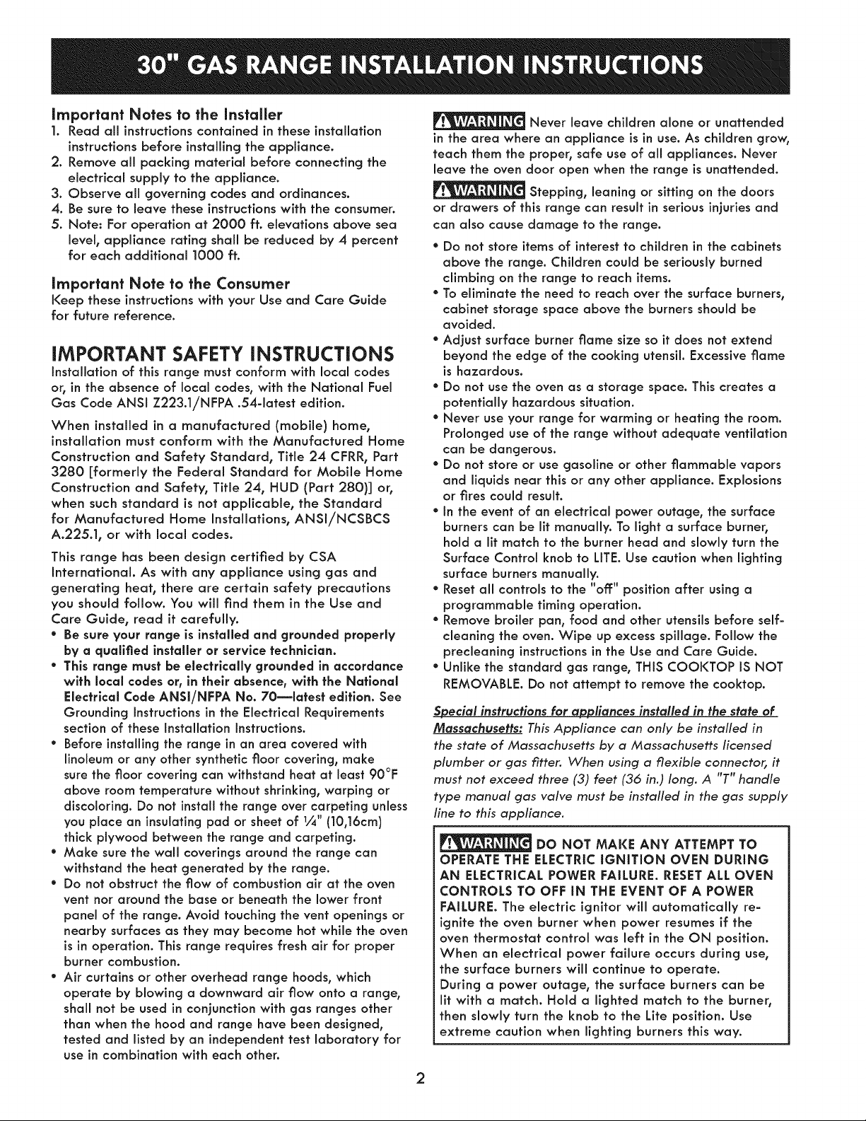
C. Level and poslflan the range = Slide range to its final
position. Insert the range leveling leg in the anti-tip bracket.
Visually verify if the anti-tip bracket is engaged. Lower the
range by adjusting the 4 leveling legs alternatively until
the range is level. Check if the range is level by placing a
spirit level on the oven rack. Take 2 readings with the spirit
level placed diagonally; take a reading in one direction and
then in the other direction. Level the range if necessary by
adjusting the leveling legs.
Leak testing of the appliance shall be conducted
according to the instructions in step 4H.
The gas supply line should be i/_" or 3/4" I.D.
NOTE:
The electric outlet can
be placed anywhere
in the hatched area.
Range side
Figure 3
Figure 4
Provide an adequate Gas Supply
When shipped from the factory, this unit is designed
to operate on 4" (10,16cm) water column (1.0 kPa)
Natural gas manifold pressure. A convertible pressure
regulator is connected to the range manifold and
MUST be connected in series with the gas supply line.
If LP/Propane conversion kit has been used, follow
instructions provided with the kit for converting the
pressure regulator to LP/Propane use.
Care must be taken during installation of range not to
obstruct the flow of combustion and ventilation air.
(2!,6 crn)
Recommended hole
location for through the
wall gas entry line.
Floor
9" _ Floor
(23crn)
(23cm)
(3.8cm)
Recommended hole
location for through
the floor gas entry
line.
Figure 5a
NOTE:
The gas entry line hole can be also placed
anywhere in the shaded area.
For proper operation, the maximum inlet pressure to
the regulator should be no more than 14" (35,56cm) of
water column pressure (3.5 kPa). The inlet pressure to
the regulator must be at least 1" (.25 kPa) greater than
the regulator manifold pressure setting. Examples: If
regulator is set for natural gas 4" (10,16cm) manifold
pressure, inlet pressure must be at least 5" (12.60cm); if
regulator has been converted for LP/Propane gas 10"
(25,4cm) manifold pressure, inlet pressure must be at
least 11" (27,9cm).
Seal the openings
Seal any openings in the floor under the range after
gas supply line is installed.
4
Page 5
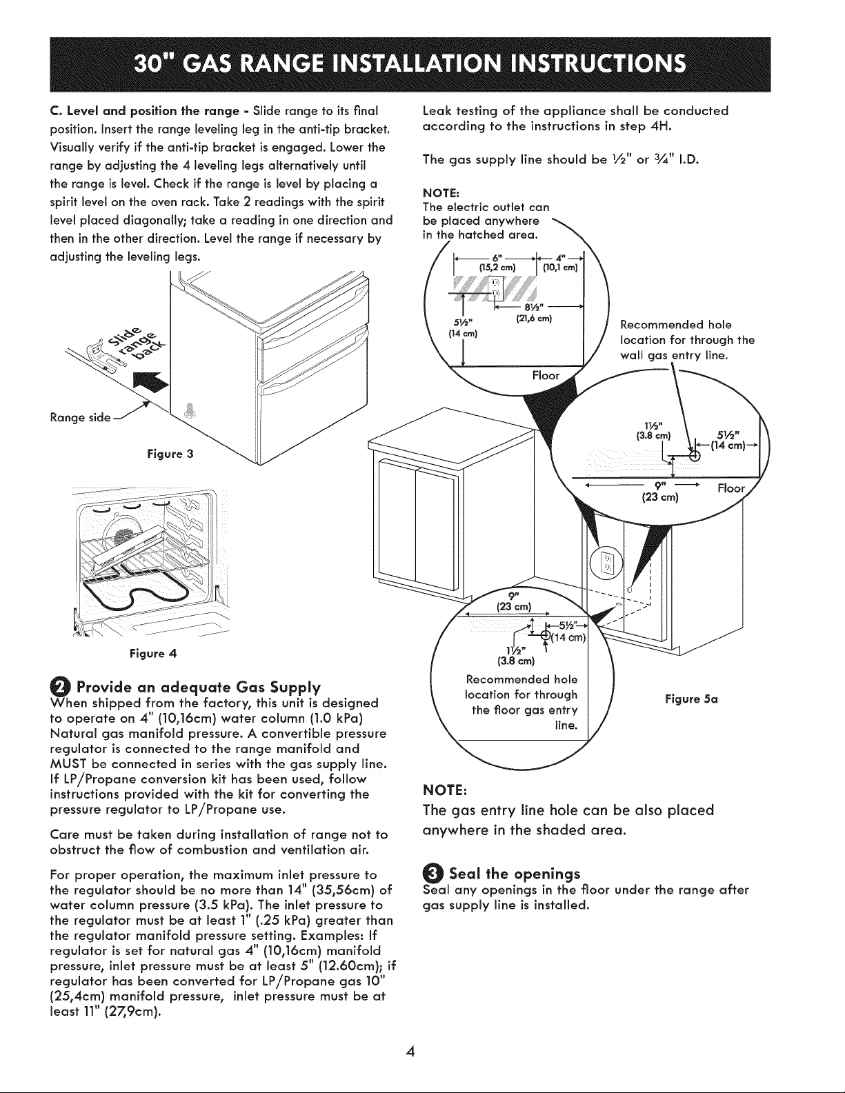
Connect the range to the gas supply
impoHanH Remove all packing material and literature
from range before connecting gas and electrical supply.
Note: To prevent leaks, put pipe joint sealant on all
external pipe threads.
Do not allow regulator to rotate on plpe
when tightening fittings.
Connection to Pressure Regulator
The regulator is already installed on the appliance.
Do not make the connection too tight.
The regulator is die cast. Overtightening may crack the
regulator resulting in a gas leak and possible fire or
explosion.
GASFLOW
Installedonthe unit
Unit Pressure
Manual
Shutoff Flare
Valve Union
Flexible
Connector
Regulator
........ hare
.... : Union
Off
Figure 5b
A. Install an external manual gas shut-off valve to gas
supply line in an accessible location outside of the
range. Be sure you know where and how to shut off
the gas supply to the range.
B. Install 1/_" flare union adapter to unit shut-off valve
using NO MORE THAN |5ff./lbs. of torque.
NOTE: Be sure to stabilize the right side of the
unit shut-off valve with adjustable wrench before
tightening ANY fittings to the unit shut-off valve.
C. Tighten the gas flexible connector and/or
appliance conduit to flare union on the left side
of the unit shut-off valve using NO MORE THAN
|Sft./Ibs. of torque. Be sure to stabilize the 1/_"
flare union adapter with an adjustable wrench
before tightening the gas flexible connector and/
or appliance conduit.
D. Install flare union adapter to external shut-off
valve.
E. Attach the gas flexible connector with the flare
union on shut-off valve.
F. Make sure both shut-off valves are in the "ON"
position.
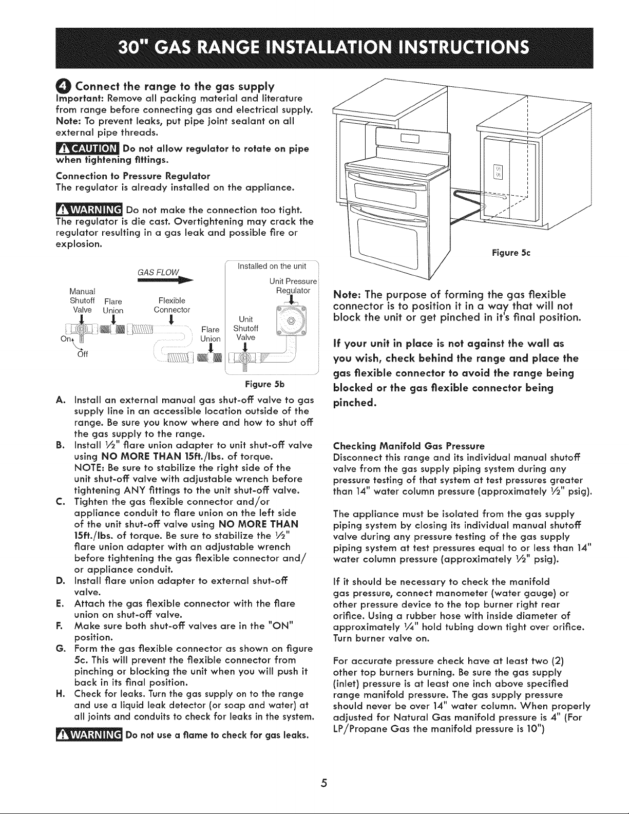
G. Form the gas flexible connector as shown on figure
5c. This will prevent the flexible connector from
pinching or blocking the unit when you will push it
back in its final position.
H. Check for leaks. Turn the gas supply on to the range
and use a liquid leak detector (or soap and water) at
all joints and conduits to check for leaks in the system.
Do not use a flame to check for gas leaks.
i
i
i
p--
Figure 5c
Note: The purpose of forming the gas flexible
connector is to position it in a way that will not
block the unit or get pinched in it's final position.
If your unit in place is not against the wall as
you wish, check behind the range and place the
gas flexlble connector to avoid the range being
blocked or the gas flexlble connector being
pinched.
Checking Manifold Gas Pressure
Disconnect this range and its individual manual shutoff
valve from the gas supply piping system during any
pressure testing of that system at test pressures greater
than 14" water column pressure (approximately 1/2" psig).
The appliance must be isolated from the gas supply
piping system by closing its individual manual shutoff
valve during any pressure testing of the gas supply
piping system at test pressures equal to or less than 14"
water column pressure (approximately 1/_" psig).
If it should be necessary to check the manifold
gas pressure, connect manometer (water gauge) or
other pressure device to the top burner right rear
orifice. Using a rubber hose with inside diameter of
approximately 1/&" hold tubing down tight over orifice.
Turn burner valve on.
For accurate pressure check have at least two (2)
other top burners burning. Be sure the gas supply
(inlet) pressure is at least one inch above specified
range manifold pressure. The gas supply pressure
should never be over 14" water column. When properly
adjusted for Natural Gas manifold pressure is 4" (For
LP/Propane (Gas the manifold pressure is 10")
5
Page 6
Electrical Requirements
120 volt, 60 Hertz, properly grounded dedicated circuit
protected by a 15 amp circuit breaker or time delay
fuse.
Note: Not recommended to be installed with a Ground
Fault Interrupt (GFI).
Do not use an extension cord with this range.
Grounding Insfrucfions
IMPORTANT Please read carefully.
For personal safety, this appliance must be properly
grounded.
The power cord of this appliance is equipped with a
3=prong (grounding) plug which mates with a standard
3=prong grounding wall receptacle (see Figure 6) to
minimize the possibility of electric shock hazard from the
appliance.
The wall receptacle and circuit should be checked by
a qualified electrician to make sure the receptacle is
properly grounded.
Preferred Method
Grounding type
wall receptacle
Where a standard 2-prong wall receptacle is installed,
it is the personal responsibility and obligation of the
consumer to have it replaced by a properly grounded
3=prong wall receptacle.
Do not, under any circumstances, cut or remove the
third (ground) prong from the power cord.
Do not, under any
circumstances, cut,
remove, or bypass
the grounding
prong.
Power supply cord with
3=prong grounding plug.
Figure 6
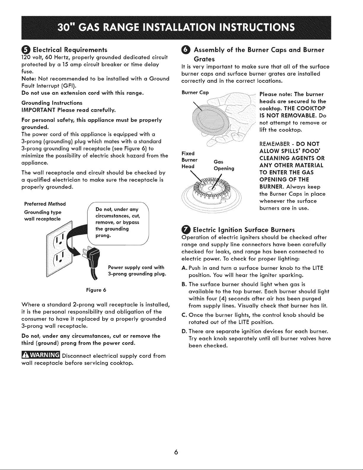
Assembly of the Burner Caps and Burner
Grates
It is very important to make sure that all of the surface
burner caps and surface burner grates are installed
correctly and in the correct locations.
Burner Cop
_:_ .........._ Please note: The burner
headsaresecuredtothe
cooktop.THECOOKTOP
iS NOT REMOVABLE. Do
not attempt to remove or
lift the cooktop.
REMEMBER - DO NOT
Fixed
Burner Gas
Head Opening
Electric ignition Surface Burners
Operation of electric igniters should be checked after
range and supply line connectors have been carefully
checked for leaks, and range has been connected to
electric power. To check for proper lighting:
A. Push in and turn a surface burner knob to the LITE
position. You will hear the igniter sparking.
B. The surface burner should light when gas is
available to the top burner. Each burner should light
within four (4) seconds after air has been purged
from supply lines. Visually check that burner has lit.
C. Once the burner lights, the control knob should be
rotated out of the LITE position.
D. There are separate ignition devices for each burner.
Try each knob separately until all burner valves have
been checked.
ALLOW SPILLS' FOOD'
CLEANING AGENTS OR
ANY OTHER MATERIAL
TO ENTER THE GAS
OPENING OF THE
BURNER. Always keep
the Burner Caps in place
whenever the surface
burners are in use.
Disconnect electrical supply cord from
wall receptacle before servicing cooktop.
6
Page 7

Adjust the "LOW" Setting of Surface
Burner Valves
Figure 7
A. Push in and turn each control to LITE until burner ignites.
B. Push in and quickly turn knob to LOWEST POSITION.
C. if burner goes out, Reset control to OFF.
D. Remove the surface burner control knob.
E. insert a thin=bladed screwdriver into the hollow valve
stem and engage the slotted screw inside. Flame size
can be increased or decreased with the turn of the
screw. Turn counterclockwise to increase flame size. Turn
clockwise to decrease flame size.
Burner Flame Size
Adjust flame until you can quickly turn knob from LiTE to
LOWEST POSITION without extinguishing the flame. Flame
should be as small as possible without going out.
Note: Air mixture adjustment is not required on surface
burners.
----_l 5/8" 4--
Main
Top
Operation of Oven Burners and Oven
Adjustments
Electric ignition Burners
Operation of electric igniters should be checked after
range and supply line connectors have been carefully
checked for leaks, and range has been connected to
electric power.
The oven burner is equipped with an electric control system
as well as electric oven and broil burner igniters. These
control systems require no adjustment. When the oven is
set to operate, current will flow to the igniter. It will "glow"
similar to a light bulb. When the igniter has reached
a temperature sumcient to ignite gas, the electrically
controlled oven valve will open and flame will appear
at the oven burner. There is a time lapse from 30 to 60
seconds after thermostat is turned ON before the flame
appears at the oven burner. When the oven reaches the
display setting, the glowing igniter will go off. The burner
flame will go "out" in 20 to 30 seconds after igniter goes
"OFF". To maintain any given oven temperature, this cycle
will continue as long as the display isset to operate.
After removing all packing materials and literature from
the oven:
A. Set the lower oven to BAKE at 300°F. See Use & Care
Guide for operating instructions.
B. Within 60 seconds the oven burner should ignite.
Check for proper flame, and allow the burners to
cycle once. Reset controls to OFF.
C. Repeat A and B with the upper oven.
D. Set the upper oven to broil. See Use and Care Guide
for operating instructions.
E. Within 60 seconds the broil burner should ignite.
Check for proper flame. Reset controls to off:.
7
Page 8

Air Shutter-Broil Burner
The approximate flame length from the burner is ] inch
(distinct inner cone of blue flame).
To determine if the broil burner flame is proper, set the
oven to broil.
If flame is yellow in color, increase air shutter opening
size (see "2" in Figure 8 ). If the entire flame is blue,
reduce the air shutter opening size.
To adjust, loosen lock screw (see "3" in Figure 8),
reposition air shutter, and tighten lock screw.
?
_91" Oven Burner Tube
Lock Screw
bOrifice Hood
Figure 8
Core, Cleonlng ond Molntenonce
Refer to the Use & Care Guide for cleaning
instructions.
If moving the range is necessary for cleaning or
maintenance, shut off: gas supply. Disconnect the gas
and electrical supply. If gas or electrical supply is
inaccessible, lift the unit slightly at the front and pull
out away from the wall.
Pull only as far as necessary to disconnect the gas and
electrical supply. Finish moving the unit for servicing
and cleaning. Reinstall in reverse order making sure to
level the range and check gas connections for leaks.
Before You Call for Service
Read the Before You Call for Service Checklist and
operating instructions in your Use and Care Guide.
It may save you time and expense. The list includes
common occurrences that are not the result of
defective workmanship or materials in this appliance.
Refer to your Use and Care Guide for Sears service
phone numbers, or call 1-800-4-MY-HOME ®.
Make sure range is level
Level the range by placing a level horizontally on an
oven rack. Check diagonally from front to back, then
level the range by adjusting the leveling legs.
After installation is completed, make sure
all controls are left in the OFF position.
LP/Propone Gas Conversion
This appliance can be used with Natural gas or LP/
Propane gas. It is shipped from the factory for use with
natural gas.
If you wish to convert your range for use with LP/
Propane gas, use the supplied fixed orifices located
in a bag containing the literature marked "FOR LP/
PROPANE GAS CONVERSION." Follow the instructions
packaged with the orifices for surface, oven and broil
burners conversion.
The conversion must be performed by a qualified
service technician in accordance with the
manufacturer's instructions and all local codes and
requirements. Failure to follow these instructions
could result in serious injury or property damage.
The qualified agency performing this work assumes
responsibility for the conversion.
Serial Plate Information
The serial plate is located on the decorative bottom trim
and it is visible when the lower oven door is opened.
Failure to make the appropriate
conversion can result in serious personal injury and
property damage.
8
Page 9

[] OVEN CIRCUIT // CIRCUITO DE HORNO i
W-6 [] iG,+GRBEN/VERDE
Iilllllllllllllllllllllllllllllllllllllllllllllllllllllllllillllll P2 =GRD iBK.*BLACK/NEGRO
UPR OV . J3 ....................... =V LED iV.-VIOLET/VIOLETA
W-14 .....................................1 J2 =v UR iT,-TAN/CAFE CLARO
LATCH N_OTOR/MOT(_R_ DE DERROJO 4
_ ./ BR-14
.....,........ [ A
W 14 /:;_:'_ / 7
I IIIIIIIIIIIIIIIIIIIIIIIIIIIIIIIIIIIIIIIIIIIIIIIIIIIIIIII I_I4III I
W 14 LWR OV "
i BOrO.VFB_][A[_ORD_COMV£CC_O": 2
COBVEC_ZO_ MofCfi #AN7 q
;BR/,,/-,4 _7_BR/W-,4 i R-14
EOO RELAY BOARD/ R 6 iw''wHZTE/BLANCO
PANEL DE RELEVADORES PANEL [NDICADOR DEL HORNO i O'"ORANGE/NARANJA
DEL HORNO iY.-YELLOW/AMAR[LLO
IIIIIIIIIIIIIIIIIIIIIIIIIIIIIIIIIIIIIIL _1111111111111_ iBR,-BROWN/CAFE
2 =ZERO CROSS BLANCO
R_14
3
J5
J7 ;
= BK 22 - iBL.-BLUE/AZUL
=
" W-22
............=r..............."
I
= R22
EOC*OISPLAY BOARD/ i R'-RED/ROJO
- BR/W. BROWN SIRIPES/WHIrE // CARE RAYAS
Y-22 : d3
: UPR MDL
= UPR BR EL_
J5
_LWR BA ELM
:IWR CON ElM
_LWR CON FN
: LWR MDL
: OV LT
OV LT
UPR BA ELM
WGL STMLS
• 'Kj ....
/ _ ! GY-14 5
L,_'JL,,_A,A 6
W-14 _b i BR-14
fr,, ..............
BAKE VALVE/
VALVULA DE MORNRAR
OPTZON 8
OPCION 9
iiiiilillllllllllllllllllllllll
I
d6 : "
:
5
:
iiiiiiiiiiiii"IiiiiiiiiiIIII_IIIIIIIIIIIIII"IIIII
" = P8 =
" UPR OV
= i=
m
: PWM REL
i=
i=
i'BK-14 BK-2O _ BK-20 BK_14
[]- ......4>
isY._REY/ORIS
LEGEND/LEYENDA
TRM.-THERMAL CIRCUIT BREAKER/INTERRUPTORi
TERMICO
UPR OV. UPPER OVEN/HORNO SUPERIOR
iLWR OV.-LOWER OVEN /HORNO INFERIOR
CODE GAUGE TE_,P"0 OSA lJ/
CODE CALIBRE
1 _8 125 0L1251 3t73
i6 125 CIt251 3173
14 125 0L1251 3173
4 12 125 OLI251 3173
5 i8 150 EXL150 3321
6 t6 150 EXL 150 3821
7 14 i50 EXI 150 3321
8 _2 150 EXL:150 3321
£ t0 150 EX[150 3321
10 t8 200 SEW-1 3122
tl 16 200 SEW-1 3122
12 12 250 3252
t3 t6 250 3252
t4 20 150 EXL 150 3321
t5 8 !50 EXL 150 3321
t6 8 60
t7 to 60
t8 10 200 SEW:I 3122
t£ 20 125 0L1251 3173
20 20 200 SEW 1 3t22
21 22 125 0L-1251 3t73
22 22 150 EXI 150 3321
23 t8 200 35Z3
24 2O 460 5107
Z5 iS 450 5107
34 16 200 3512
LATCH MOTOR/
MOTOR DE CERROJO
No c
i)ooR SWI]OH/
INTERRURTOBRE PMERTA
5335
BK 14
BAKE VALVE/ =
VALVULA BE MORNEAR
_,-_1 ENMENDIDO DE NORNEAR :
_j Y 14
CONVECT][ON ELEMENTI
0 5 ELEMENTO DE CONVECCION 0 5 _ "
;; i: ............... <'_ .............. : : CONV
7 " =
BAKE EGNETER/
,_ _ - •
i OPTION
i OPCION
CAUTION:DISCONNECT POWER BEFORE SERVICING UNIT.
LABEL ALL WIRES PRIOR TO DISCONNECTION WHEN SERVICING CONTROLS.
WIRINGS ERRORS CAN CAUSE IMPROPER AND DANGEROUS OPERATION.
VERIFY PROPER OPERATION AFTER SERVICING.
ATENCtON:CORTAR LA CORRIENTE ANTES DE REALIZAR EL MANTENIMIENTO DEL ELECTRODOMESTICO.
ETIQUETE TODOS LOS CABLES ANTES DE DESCONECTAR CUANDO HAGA EL SERVICIO A LOS CONTROLES.
ERRORES AL VOLVER A ENSAMBLAR LOS CABLES PUEDE CAUSAR FALLAS U OPERACIONES PELIGROSAS.
VERIFIQUE LA CORRECTA OPERACION DESPUES DEL SERVICIO.
IIIIIlllllllllllllllllllllllll
;,,,,,,,,,,,,,,,,,,,,,,,,,,,,,,,,,,,,,; :
IIIIIIIIIIIII1_111111111111_111111111111 IIIIII
_LWROV : __> _] TEMPERATURE PROBE/
9
jiB<-'4
P6 -
: _BK-I4 \ \ [W_ TEMPERATURE PROBE/
_/= / / SONDA DE TEMPERATURA
oPROV
:BK-14 \ \ LWR OV
PIO = LATCH MOTOR/
] "BK- 14 -- BK-14
MOTOR DE BERROJO
[]
[]
;,,,,,,,,,,,,,;
SONOA BE TEMPERAIURA
Page 10

COOKTOP CIRCUIT // CIRCUITO DE PLANCHA DE COCINAR
TOP BURNER _GNTTER
QUEMAOOR DE ENCENNIGO SUPERIOR
j--.
w4°/
TOP BURNER IGNITER
QUEMADOR DE ENCENDIDO SUPERIOR
w4oI_ ;
TOP BURNER IGNITER !
QUEMADOR DE ENCENDIDO SURER[OR I
w- o ; OPTION
TOP BURNER IGNITER
QUEMADOR DE ENDENDIDO SUPERIOR
TOP BURNER IGNITER
OUE_ADOR BE ENCENDIDO SUPERIOR
IGNITER MODULE BOARD
CUADBO DE MODULO DE ENCENDIDO
OPClON
rl_ F
R-14_
1 i
1 /. F
r*', r
R-14_
W-14 \
120VAC /ABUT
A2 4
JlJ._ TRANSFORMER/
A1 f_Y'A3 TRANSFORMADOR
t20VAC
IN
N L
INTERRUPTOB ENCENDIDO
IGNITER SWITCH
R 14
INTERRUPTOR ENCENDIDO
IGNITER SWITCH
1
R-14 OPIION
IGNITER SWITCH i
INTERRUPTOR ENOENDIDO I
' OPOION
R t4
INTERRURTOR ENCENDIDO
IGNIIER SWIgCH
R-14
INTERRUPTOR ENOENDIDO
IGNI1ER SWITCH
R_14
CONNECTOR
CONEOTOR
A
CAUTION:DISCONNECT POWER BEFORE SERVICING UNIT.
LABEL ALL WIRES PRIOR TO DISCONNECTION WHEN SERVICING CONTROLS,
WIRINGS ERRORS CAN CAUSE IMPROPER AND DANGEROUS OPERATION,
VERIFY PROPER OPERATION AFTER SERVICING.
ATENCION:CORTAR LA CORRIENTE ANTES DE REALIZAR EL MANTENIMIENTO DEL ELECTRODOMESTICO.
ET[QUETE TODOS LOS CABLES ANTES DE BESCONECTAR CUANO0 HAGA EL SERV[CIO A LOS CONTROLES.
ERRORES AL VOLVER A ENSAMBLAR LOS CABLES PUEDE CAUSAR FALLAS U OPERAC[ONES PEL[GROSAS,
VERIFIQUE LA CORRECTA OPERACION DESPUES DEL SERVICIO,
10
CODE GAUGE TEMP.'C CSA UL
CODIGO MEDIDA
1 16 12S 011251 3173
2 16 t25 0LI251 3173
3 14 125 CL1251 3173
4 12 125 CL1251 3173
5 18 150 EXL-150 3321
6 16 t50 EXL-150 3321
7 14 150 EXL_150 3321
8 12 150 EXL 150 3321
9 10 150 EXL 150 3321
10 18 200 SEW+I 3122
11 16 200 S_l-1 3122
12 12 250 3252
13 16 250 3252
14 20 150 EX[_150 3321
15 8 t50 EXI-150 3321
16 8 60
17 10 60
18 10 200 SEW-1 3122
19 20 125 0L1251 3173
20 20 200 SEVI*I 3122
21 22 125 3266
22 22 150 10109
23 18 200 3573
34 16 200 3512
35 18 200 3512
37 14 20O 3512
40 18 200 3204 OR/OU 10202
4t 20 200 3512
Page 11

LA INSTALACION Y EL SERVICIO DEBEN SER EFECTUADOS PeR UN INSTALADOR CALIRCADO. / vf__,_O_-_\,
IMPORTANTE: GUARDE ESTAS INSTRUCCIONES PARA use DEL iNSPECTOR LOCAL DE ELECTRICIDAD.//__./_
LEA Y GUARDE ESTAS INSTRUCCIONES PARA REFERENCIA FUTURA.
F_ PARA SU SEGURIDAD: No amanece nl utlllce gasollna u otros vapores y
liquldos innamables en la proxlrnldad de este o de cualquler otto artefacto.
F._]_ Si la informaci6n contenlda en es|e manual no es
segulda exactamente, puede ocurrlr un incendlo o explosi6n causando
dafios materlales, lesi6n personal o la muerte.
PARA SU SEGURIDAD:
rune almacene nl utillce gasolina u otrosvapores y liquldos inflamables en la
proxlmidad de _ste e de cualquler otro arfefacto.
tuQUE DEBEHACER SI PERCIBEOLOR A GAS:
* No trate de encender nlng_n artefacto.
* No toque nlng_n interrupter el_ctrlco; no use nlng_n tel_fono en su edificlo.
* Llame a su proveeder de gas desde el tel_fono de un veclno. Siga las
instrucclonesdel proveedor de gas.
* Si no Iogra comunlcarse con su proveedor de gas, Ilame al departamento de
bomberos.
_La instalaci6n Vel servlclo de mantenlmlento deben set efectuades per un
instal°dot calificado, la agencla de servlclo o el proveedor de gas.
Nota: Electrodom6sticos instalados en el
estado de Massachusetts (yea la p6gina 2).
* Todas las estufas pueden
vo_carse.
* Esfo podria resultar en
lesiones personales.
* Instale el disposifivo
anfi-vuelcos cluese ha
empacado jun_'ocon esta
estufa.
* Vea las instrucciones
par° instalaci6n.
Vista
Un m_nimo de 30" de espacio entre la parte superior de la
superficie para estufa y el rondo no protegido de un gabinete de
metal o madera; o un m_nimo de 24" cuando el fondo de metal o
madera del gabinete esta protegido por no menos de _¼" de material
retardante, con una hoja de acero de no menos MSG No.28, 0.015"
de acero inoxidabler 0.024" de aluminio o 0.020" de cobre. 0" es
el espacio m_nimo para la parte trasera de la estufa. Siga todos los
requerimientos de medidas antes proporcionados para evitar da_os
a la propiedad: peligro de encendidos potenciales o superficies y
cortes de gabinetes que sean incorrectos.
Vista
lateral
_,=
i
=
entre ios gab_ne|es_
_ _°do de _a V _° parte superlorl' ]
.....................estufa..............................._e!acoci"a...................._il
I_ 301/8"_ _o_j= ,i.g_,espacio por debajo delclparle
Para effmlnar el rlesgo de quemaduras o incendlo
cuando irate de alcanzar obje_os per sobre unldades
de superflcle calenfadas, debe evffarse que los
gablne|es para almacenamlento es_6n Iocaffzados
enclma de la superflcle de la es_ufa. Si exls_en
gablnefes de a_macenam_en|o, el rlesgo puede set
reducldo ins_alando una camp°n° de es_ufa que
se proyecte en form° horlzon|al a una dlsfancla
minima de 5" mas ala del fondo de los gablnefes.
superior de |a cocina y |a par|e _asera.
Espacios y dimensiones
1. Ublcaci6n_Examlne el lugar en el cua_ va a set
ins_a_ada la esfufa. Determine la existencia de suministro
el_ctrico adecuado y la estabilidad del piso.
Impreso en los Estados Unidos
2. Se deben usar las medldas indlcadas. Las dimensiones
indicadas proporcionan espacio m_nimo. La superficie
de contacto debe ser s61ida y estar a nivel.
318201790 (0912) Rev.A
Page 12

Notas importantes para el instalador
1. Lea todas las instrucciones contenidas en este manual
antes de instalar la estufa.
2. Saque rode el material usado en el embalaje de la estufa
antes de conectar el suministro el6ctrico a la estufa.
3. Observe todos los c6dJgos y reglamentos pertinentes.
4. Deje estas instrucciones con el consumidor.
Nora importante al consurnidor
Conserve estas instrucciones y el Manual del usuario para
referencia futura.
IMPORTANTES INSTRUCCIONES DE
SEGURIDAD
Instalaci6n de esta estufa debe cumplir con redes los c6digos
locales, o en ausencia de c6digos locales con el C6digo Nacional
de Gas Combustible ANSI Z223J/NFPA .54--01fima edici6n.
Si la cocina se instalaen una casa m6vil (caravana), la instalaci6n
deber6 realizarse de acuerdo a los est6ndar de seguridad
Manufactured Home Construction and Safety Standard (Est6ndar
de seguridad y construcci6n de casa prefabricadas), Tffulo24 CFR,
Secci6n3280 [anteriormente denominada Federal Standard for Mobile
Home Construction and Safety (Est6ndarfederal para seguridady
construcci6n de casas prefabricadas), Tffulo 24, HUD (Secci6n 280)]
o,en case de que dicho est6ndar no sea aplicable, deber6 seguirsela
norma marcada per el Standard for Manufactured HomeInstallations,
ANSI/NCSBCS A225.1, o bien, toda la normafiva legal existente
referente a casas m6viles.
El disefio de esta estufa ha side certificado per la CSA internacional.
En _ste come en cualquier otto artefacto que use gas y genere
calor, hay ciertas precauciones de seguridad que usted debe
seguir. Estas ser6n encontradas en el Manual del Usuario, I_alo
cuidadosamente.
* Aseg0rese de que la estufa sea insfalada y conectada a tierra en
forma apropiada per un insfalador califlcado o per un t_cnice.
* Esta estufa debe ser el_ctricamente puesta a tierra de acuerdo
con los c6digos locales, o en su ausencia, con el C6digo El_ctrico
Nacional ANSI/NFPA No. 70, 01tima edici6n. Vea las instrucciones
para la puesta a tierra.
, Antes de instalar la estufa en un 6rea cuyo piso este recubierto
con lin61eo u otro ripe de piso sint_tico, aseg0rese de que _stos
puedan resistir una temperatura de per Io menos 90°F sobre la
temperatura ambiental sin provocar encogimiento, deformaci6n o
decoloraci6n. No instale la estufa sobre una alfombra al menos
que coloque una plancha de material aislante de per Io menos
1/4 pulgada, entre la estufa y la alfombra.
* Aseg0rese de que el material que recubre las paredes alrededor
de la estufa, pueda resistir el calor generado per la estufa.
* No obstruya el flujo del aire de combusti6n en la ventilaci6n
del horno ni tampoco alrededor de la base o debajo del panel
inferior delantero de la estufa. Evite tocar las aberturas o 6reas
cercanas de la ventilaci6n, ya que pueden estar muy calientes
durante el funcionamiento del horno. La estufa requiere aire
fresco para la combusti6n apropiada de los quemadores.
* No se deben usar las cortinas de aire o cualquier otra campana
de ventilaci6n superior que sople aire hacia abajo sobre la estufa
a gas a menos que la campana de ventilaci6n y la estufa hayan
side disefiadas, probadas y certificadas per un laboratorio de
pruebas independiente para el use combinado de la una con la
otra.
Nunca deje nifios solos o desafendidos en un
6rea donde un artefacto est6 siendo usado. A medida que los niSos
crecen, ens_Seles el use apropiado y de seguridad para redes
los artefactos. Nunca deje la puerta del borne abierta cuando la
estufa est6 desatendida.
No se pare, apoye o siente en las puertas o
cajones de esta estufa pues puede resultar en serias lesiones y
puede tambi_n causar dafio a la estufa.
* No almacene arficulos que puedan interesar a los nifios en los
gabinetes sobre la estufa. Los nifios pueden quemarse seriamente
tratando de trepar a la estufa para alcanzar estos arficulos.
° Los gabinetes de almacenamiento sobre la estufa deben
ser evitados, para eliminar la necesidad de tener que pasar
sobre los quemadores superiores de la estufa para Ilegar a
eilos.
° Ajuste el tamale de la llama de los quemadores superiores de
tal manera que 6sta no sobrepase el horde de los utensilios
de cocinar. La llama excesiva es peligrosa.
° No use el homo come espacio de almacenaje. Esto crear6
una situaci6n potencialmente peligrosa.
° Nunca use la estufa para calentar el cuarto. El use
prolongado de la estufa sin la adecuada ventilaci6n puede
resultar peligroso.
° No almacene ni ufilice gasolina u otros vapores y Ifquidos
inflamables en la proximidad de 6ste o de cualquier otto
artefacto el6ctrico. Puede provocar incendio o explosi6n.
° Encaso de una interrupci6n del servicio el6ctrico, es posible
de encender los quemadores de superficie a mane. Para
encender un quemador de superficie, acerque un f6sforo
encendido del cabezal del quemador, y gire delicadamente
el bot6n de control de superficie a LITE (encendido). Tener
cuidado al encender los quemadores a mano.
* Ajuste todos los controles a la posici6n "OFF" (apagada)
despu6s de haber hecho una operaci6n con tiempo
programado.
* Saque la asadera, alimentos o cualquier otro utensilio antes
de usar el ciclo de autolimpieza del horno. Limpie todo
exceso de derrame de alimentos. Siga las instrucciones de
prelimpiado en el Manual del Usuario.
° A diferencia de la gama est6ndar cocinas de gas, ESTA
PLANCHA DE COCINA NO ES MOVIBLE. No intente quitar
la plancha de cocina.
_Apara#os Instalados en el estado de Massachuse##s: Este Aparato
s61o puede ser instalado en el estado de Massachusetts per un
plomero o a]ustador de gas licenciado de Massachuseth Este
aparato se debe instalar con un largo conector f)exibfe de gas
de tres (3) pies/36 pulgadas. Una vddvula manual de gas de ripe
manila de forma de "T" se debe instalar en la I(nea del suministro
de gas de este aparato.
NO INTENTE ENCENDER EL HORNO
DE IGNICI6N ELECTRICA DURANTE UN APAGON
DE LUZ. COLOQUE TODOS LOS CONTROLES EN LA
POSICI6N DE "APAGADO" CUANDO SE PRODUZCAN
SITUACIONES DE ESTE TIPO.
El encendedor el_ctrico, volver6 a encenderse
autom6ticamente al volver a conectarse el suministro de
energfa el_ctrica tras un apag6n si se hart dejado los
controles en la posici6n de "ENCENDiDO".
Si se produce un apag6n el_ctrico cuando est6 ufitizando
la aplicaci6n, los quemadores de superficie continuar6n
en funcionamiento y podr6 encenderlos con una ceriHa.
Coloque una cerilla encendJda al lade del quemador y, a
confinuaci6n, gire lentamente el mando hasta colocarlo en
a posici6n LITE de encendJdo. Extreme las precauciones la
encender el quemador de este mode.
2
Page 13

Antes de comenzar
Herramientas que va a necesitar
Para paras de nivelaci6n y monfura anfi=vuelco:
• Llave ajustable o alicates :_r_: _,
• Llave para apretar tuercas de 5/]6" o un ;:__-_ _
destornillador de cabeza plana ................................
• Taladro el_ctrico y una broca de _H_ _
1/8" (broca de taladro de horrnig6n_ J
de 5/32" si se instala sobre
hormig6n)
• Nivel & Cinta de rnedici6n
Para la conexi6n al sumlnistro de agg_
• Pinza
• Brocha
Para el a iuste de la llama de los quemadores:
• Destornilladores de estrella _ y de cabeza
plana __
Para la conversi6n a gas (PL/Propano o gas natural):
• Llave de boca de 1/2" _!_
Maferlal adlcional que va a necesltar:
• V61vula de desconexi6n de la ffnea de gas
• Sellador para uniones de tuberfas que
resista la acci6n , _ .... _NT_l
• Un conducto de metal flexible (V_ NPT .........
x 3/4" o de 1/_" de D.L) con dise_o
cerfificado per CSA international. Ya
que las tuberfas rfgidas restringen el
rnovirniento de la cocina, se recornienda
el use de tuberfas flexibles nuevas
(de entre 1,20 a 1,50 rnts) durante la
instalaci6n y cada vez que se vaya a instalar de
nuevo o se carnbie de lugar posteriorrnente.
• Utilice siernpre los dos (2) adaptadores de carnpana
(1/_" NPT x 3/4" o de 1,,_"D.L) que se surninistran con
el conducto flexible nuevo para la conexi6n de la
COCina.
del gas propano/PL I-i_s_T_
Pasos de insfalaci6n esf6ndar
Instrucci6n para la instalaci6n del braquete
anti-basculante
Nora irnporfante de segurldad
Para reducir el riesgo de inclinaci6n de la cocina, 6sta
debe ser asegurada hacia el piso con las fijaciones de
anti-inclinaci6n y los tornillos que vienen con la cocina.
Si no instala las fijaciones, corre el riesgo que su cocina
pueda inclinarse si pone dernasiado peso sobre la
puerta abierta o si un nifio sube sobre 6sta. Esto podrfa
ocasionar graves causadas per derrarnes de ffquidos
calientes o per la propria cocina.
Si la cocina es trasladada a otro lugar, las fijaciones de
anti=inclinaci6n deben tarnbi6n ser trasladadas y instala-
das con la cocina.
Las instrucciones provistas sirven para instalaci6n en
suelo de rnadera o concrete. AI fijar los tornillos al suelo,
asegOrase que no atraviesen la instalaci6n el$ctrica o de
fontanerfa.
A. Locafice la fijaci6n usando el papel mmodelo-
Localice la posici6n de la fijaci6n colocando la plantilla
sim_tricarnente a la ffnea central de la apertura. El
soporte antivuelco puede instalarse en el lade izquierdo
o derecho en la parte posterior de la estufa. Marque la
ubicaci6n de los agujeros de tornillos come se rnuestra
en el papel.
Figura 1
B. Perforaci6n de agujeros plloto y mmonfurade sujeci6n
- Perfore un agujero piloto de 1/8" en el lugar en el que
se vayan a instalar los tornillos. Si la rnontura se va a
instalar a en la pared, practique un agujero piloto con
una inclinaci6n aproxirnada de 20 ° hacia abajo. Si la
rnontura se va a instalar sobre horrnig6n para suelos ce-
r6rnicos, practique un agujero de 3/16" con una profun-
didad de 1=3/4". Los tornillos que se surninistran pueden
utilizarse en horrnig6n o rnadera. Para fijar la rnontura
en su sitio, utilice un destornillador de cabeza plana o
una Ilave para apretar tuercas de 5/16".
MONTURA DE SUJECI6N
Pafa de "-_
nivelaci6n
Moniaje _ II _a anflvueko
en suele
MONTAJE EN PARED O SUELO)
e--1=1/4" Max.
Montaje
en pared
ri ..... ; -• •
Place
de pared
MONTURA DE SUJECiON (s6_oMONTAJEENSUELO)
Pata de "==_1 I_.==M6s de
nivelaci6n _ i 1-1/4"
i Pared
i
Montaje
en suelo
Montura antivuelco
Figura 2
Page 14

C. Nivele la coclna V coloque la coclna en su lugar.
Deslice la estufa a su lugar. Colocar la pata niveladora
dentro del braquete anti-basculante. Verifique visualmente
que los soportes antivuelco est6n correctamente
enganchados (anclados). Nivele la cocina. Nivele ia
estufa si es necesario, ajustando las 4 paras niveladoras
con una llave ajustable. Para verificar que la cocina esta
nivelada coloque un nivel en las parrillas interior del horno.
Tome mfnimo 2 lecturas con el nivel0 coloque el nivel en
diagonal para que la cocina este nivelada de atr6s hacia
adelante, si es necesario ajuste las patas niveladoras.
Lateral de
la cocina
Figure 3
Un examen de detecci6n de fucjas del aparato debe ser
realizado secjgn las instrucciones en el paso 4h.
La I{nea de fuente de gas debe set de 1/2" o de 3,,_"
NOTA:
Toma el_ctrica puede ser
Iocalizado en cualquier
parte dentro del 6tea.
Pared: Acjujero
recomendado para
entrada del tubo
de gas
Suelo
Suelo
Figure 4
t_ Proporcione un suminisfro de gas adecuado
Cu6ndo se env{a de la f6brica, esta unidad ha sido
ajustada para operar con un mgltiple de admisi6n para gas
natural de 4" (10.16 cm)(L0 kPa). Un recjulador de presi6n
convertible esta conectado a la v61vula distribuidora y
DEBE ser conectado con la tuberfa del suministro de gas.
Si el juecjo de conversi6n del propano LP/Propano se ha
utitizado, sicjue las instrucciones proporcionadas el juecjo
para convertir el recjutador de presi6n al uso de LP/Propano.
Se debe de tener cuidado durante la Jnstalaci6n de la estufa
para no obstruir el flujo de aire de combusti6n y ventitaci6n.
Para la operaci6n apropiada, la m6xima presi6n de entrada
al regulador no debe exceder la presi6n de una columna
de agua de 14" (35,56 cm) (3.5 kPa). La presi6n de entrada
al regulador debe ser por Io menos 1" (.25 kPa) m6s grande
que la v61vula dJstribuidora. Ejemplos: Si regulador se pone
para el gas natural con una presi6n de 4" (10,16 cm), la
presi6n de entrada al regutador debe set por Io menos 5"
(]2.60 cm); si el regutador se ha converfido para gas LP/
Propane 10" (25,4 cm) la presi6n de entrada al regulador
debe ser por Io menos 11" (27,9 cm).
(23 cm)
(3.8cm)
Suelo: Acjujero
recomendado
para entrada
Figure 5a
del tubo de gas.
NOTA:
El agujero de la entrada del sistema de gas puede
estar localizado en cuaiquier parte del 6rea
punteada.
0 Selle las aperturas
Sella todas las aperturas en la pared detr6s de la estufa
y en el suelo debajo de la estufa despu_s que la ffnea del
suministro de gas sea instalada.
4
Page 15

Conecte la estufa al suministro de
Importante: Quite todo el material de embalaje y
literatura de la estufa antes de conectar el gas y la
fuente el_ctrica. Nota: Para evitar fugas, aplique sellador
de tuberfas en todas las partes roscadas machos
(exterior) de la tuber[a.
No permlta que el regulador glre sabre la
tuber[a aJ apretar las unlones.
Conecte el Regulador de Presi6n
El regulador de presi6n esta ya instalada para la estufa.
No haga la conexi6n demasiado
apretada. El regulador es de die cast. El apretar
demasiado puede agrietar el regulador dando par
resuItado una fuga de gas y un fuego o una explosi6n.
Flujo de gas ii Instalado en la unldad
V61vula Adaptador de presi6n
manual para uni6n de Flexible _:
externa campana conducto Adaptador
,4..... de campana manual del ....
Off i....... _\, _ _ J
Figura 5b _ .
A. Instale una vc_Ivula manual externa para cierre de gas
hacia la l[nea de suministro de gas que tenga una
ubicaci6n de f_cil acceso fuera de la cocina. Aseg6rese
de conocer d6nde y c6mo se cierra el suministro de gas
hacia la cocina.
B. Instale un adaptador para uni6n de campana de 1/2"
hacia el v61vula manual del unidad usado NO MAS DE
15pies!Ibs de torque. NOTA: Asegurar estabilizaci6n del
lado derecho de la v61vula manual de la unidad antes
de ajustar algOn complemento a la unidad.
C. Apretar el conector flexible de gas y!o el conducto del
electrodom6stico para unir con la v61vula manual de
la unidad usando NO MAS DE 15 pies!Ibs de troqu&
Asegurar estabilizaci6n del adaptador para uni6n
de campana de 1/2" y ajustar con la pinza antes de
apretar conector flexible de gas y/o conducto del
electrodom6stico.
D. Instale el adaptador de la unJ6n de campana hacJa la
v6ivula manual externa de cierre.
E. Conecte el flexible conducto a la uni6n de campana en
la v61vula manual externa de cierre.
F. AsegOrese que la v61vula manual del unidad y la v61vula
manual externa se encuentra en la posici6n de encendi-
do "ON".
G. Distribuir el conector flexible de gas coma Io muestra fig.
5c a 5e. Esto ayudar6 a prevenir picaduras o bloqueo de
la unidad cuando la unidad sea Iocalizada a su posici6n
final. Ajustar el sujetador proporcionado tal cual la posi-
ci6n mostrada.
H. Veriflque si existen fugas. Encienda el suministro de gas
hacia la cocina y use el detector de derrames de I[qui-
dos en todas las uniones y conductos para comprobar la
existencia de fugas en el sistema.
No use fuego para comprobar la existen-
cia de fugas de gas.
f
+ :
gas
Regulador
Figure 5c
Nora: El prop6sito de la distribuci6n del conector
flexible de gas es poder posicionar Io de manera que
no se bloque la unidad o se pique en su posici6n final.
Si la unidad no se encuentra pegada a la pared
coma usted desea, revise que los tubas de gas que
se encuentran en la parte posterior no interfieran,
verifique que al colocar la unidad los tubas flexibles
no se encuentran bloqueados, tenga cuidado de no
romper los tubas flexibles al coloca la unidad
Revisi6n de la presi6n de gas en el colector
Desconecte la cocina y su v61vula de cierre individual del
sistema de tuberia del suministro de gas durante cual-
quier prueba de presi6n de ese sistema para presiones de
prueba superiores a 14" de presi6n de coiumna de agua
(aproximadamente V2" psig).
La aplicaci6n debe aislarse del sistema de la tuberia de
suministro de gas cerrando su v61vula de cierre manual
individual durante cuaiquier prueba de presi6n dei sis-
tema de tuberia de suministro de gas para presiones de
prueba iguaies o mayores a 14" de presi6n de coiumna
de agua (aproximadamente V2" psig).
Si fuera necesario revisar la presi6n de gas en el colecto b
conecte el man6metro (medidor de agua) u otro disposi-
tivo de presi6n al oriflcio posterior derecho del quemador
superior. Usando una manguera de caucho con un di6me-
tro interior de
aproximadamente V4", sostenga fuerte la tuberia hacia
abajo
sabre el oriflcio. Encienda la v61vula del quemador.
Para una revisi6n exacta de la presi6n, tenga par Io me-
nos otros dos (2) quemadores superiores. Aseg0rese que la
presi6n del suministro de gas (entrada) se encuentra par
Io menos una pulgada par encima de la presi6n especifl-
cada en el colector de la cocina. La presi6n del suministro
de gas nunca debe encontrarse par encima de 14" de
la columna de agua. Cuando se encuentra debidamente
ajustado para Gas Natural, la presi6n en el colector es 4"
(para PL/Gas Propano, la presi6n en el colector es 10").
5
Page 16

Requisitos el_ctricos
120 voltio, 60 Hertzio, circuito dedicado
apropiadamente puestos a tierra protegido per un
circuito de amperio o fusible de demora de tiempo de
15 amp.
Nora: no es recomendado instalarlo con un Interrupter
(GFI) de puesta a tierra.
No ufillce una exfensi6n con esta estufa.
Insfrucclones de puesfa a tlerra
IMPORTANTE Per favor lea con culdado.
Para la segurldad personal, esfe aparafo debe set
puesto a flerra apropladamente.
El cable del surninistro el_ctrico de esta estufa est6
equipado con un enchufe de tres patinas (para puesta
a tierra) que coincida con un enchufe de pared
est6ndar con puesta a tierra de tres patinas (figura
6) para minirnizar la posibiNdad que se produzcan
descargas el6ctricas.
El cliente deber6 encargar a un t6cnico para
asegurarse de que el enchufe se encuentra
debidamente conectado a tierra y polarizado.
Montaje de las Cabezas, de las Tapas de los
Quemadores V de las RejiHas de los Quemadores
Es muy importante asegurarse de que todas las
cabezas, las tapas de los quemadores superiores y las
rejiNas de los quemadores superiores est6n instaladas
correctamente yen sus lugares correctos.
Tapa del
Quemador
.... _/- -7J-777- /
\j
Apertura
de gas
Nola: Las cabezas del
quemador de la superficle
estcin sujetas a la cublerfa
de cocci6n. LA CUBIERTA
DE COCCION NO ES
DESPItENDIBLE. No intente
quitar o levantar la cubierta
de cocci6n.
RECUERDE -- NO PEItMITA
QUE PENETREN DERRAMES
DE ALIMENTO% AGENTES
DE LIMPIEZA O NINGON
OTRO MATERIAL EN LA
ABIERTURA DEL SOPORTE DIE
LA TOBERA DE GAS. Siernpre
mantenga las tapas de los
quemadores y las cabezas de
los quemadores en su lugar
cuando use los quemadores.
M_todo preferide
Enchufe de pared
con toma de tierra
No torte, retire o
/
derribe, bajo ninguna I
circunstancia, la patilla I
ctela torna ctetierra del I
/
enchufe J
Cable de surninistre
el_ctrico con enchufe con
terna cte tierra
Figurcl 6
En lugares en los que aya un enchufe de pared
est6ndar de dos patinas, el cliente tendr6
responsabiNdad directa y la obNgaci6n de
reemplazarlo per un enchufe de pared de tres patinas
debidamente cableado a tierra.
Bajo nlnguna clrcunstancla, corte, retire o derrlbe
la fercera patilla (de foma de fierra) del cable del
sumlnlstro de energ_a el_ctrlca.
Desenchufa el cable del surninistro
de energfa el_ctrica del enchufe de pared antes de
rnantener la plancha de cocina.
Comprobaci6n de los Encendedores
El funcionamiento de los encendedores el_ctricos
debe ser comprobado despu6s de que la estufa y los
conectores a la tuberfa de suministro de gas hayan
side comprobados para las fugas y la estufa haya
siclo conectada el_ctricamente. Para comprobar que el
encendido sea correcto:
A. Empuje y gire un bot6n control del quemador
superior hasta la posici6n LITE (encender). Se
podrfa oir el encendedor haciendo chispas.
B. El quemador se deber6 encender en cuatro (4)
segundos para un funcionamiento normal, despu6s
de que el aire haya sido purgado de la tuberia
de suministro de gas. Controle visualmente que el
quemador se haya encendido.
C. Despu6s de que el quemador se haya encendido_
la plancha de cocina debe ser cjirada fuera de la
posici6n LITE.
D. Cada quemador tiene su encendedor individual.
Controle las perillas separadamente hasta que
todas las v61vulas hayan siclo controladas.
6
Page 17

OAjuste de la Posici6n LOW (BAJA) Para la
V61vula del Quemador Superior
Figura 7
A. Gire el bot6n de control a la posici6n LITE
(encender) hasta que el quemador encienda.
B. R6pidamente gire el bot6n de control a la POSICI6N
MAS BAJA.
C. Si el quemador se apaga. Mueva el control a la
posici6n OFF (apagada).
D. Saque la perilla de control del quemador superior.
E. Inserte un destornillador piano peque_o en el
hueco del v6stago del a v61vula basra enganchar
el tornillo interior. El ramada de la llama puede ser
aumentado o disminuido girando el tornillo.
Ajuste el ramada de la llama basra que pueda pasar
r6pidamente de la posici6n LITE basra la posici6n MAS
BAJA sin que se apague la llama. La llama debe ser Io
m6s peque_a posible sin que se apague.
Operaci6n de Quernadores del Homo y
Ajustes de Homo
Quemadores de ignlci6n el_ctrlca
La operaci6n de los encendores el_ctricos debe de set
revisada despu6s de que la cocina y los conectores
de la l[nea de suministro haya sido cuidadosamente
revisada para descartar fucjas y que la cocina haya sido
conectada a la corriente el_ctrica.
El quemador del homo est6 equipado con un sistema de
control el_ctrico as[ coma un encendedor de quemador
de homo el_ctrico. Si su modelo esta equipado con un
quemador de asado central superior, tambi6n contar6
con un encendedor de quemador el_ctrico. Estos
sistemas de control no requieren ajustes. Cuando el
homo esta configurado para operar, la corriente flair6
hacia el encendedor y tendr6 un resplandor de manera
similar a una bombilla de luz. Cuando el encendedor a
alcanzado una temperatura suficiente para encender el
gas, la v61vula del homo controlada el6ctricamente se
abrir6 y el fuego aparecer6 en el quemador del horno.
Hay un lapso de tiempo de 30 a 60 segundos despu6s
de que el termostato se enciende y antes de que la
llama aparezca en el quemador del homo. Cuando el
homo alcanza la configuraci6n del dial, el encendedor
resplandeciente se apagar6. La llama del quemador
desaparecer6 par 20 a 30 segundos despu6s de que
el encendedor se apaga. Para mantener cualquier
temperatura de homo dada, este ciclo continuar6 tanto
coma el dial (o visualizador) est6 configurado para
operar.
Despu6s de retirar todos los materiales del empaque y la
literatura del homo:
A. Fije el homo inferior en HORNEAR (BAKE) a 300°F.
Vea la gu[a de Usa y Cuidado para conocer las
instrucciones de funcionamiento.
B. En 60 segundos el quemador del homo se encender6.
Revise que exista un fuego adecuado, y permita
que el quemador cumpla su ciclo una vez. Gire los
controladores hacia OFF (APAGADO).
C. Repita paso A y B con el homo superior.
D. Fije el homo superior en ASAR (BROIL). Vea la gu[a
de Usa y Cuidado para conocer las instrucciones de
funcionamiento.
E. En 60 segundos el quemador de asar debe de
encenderse. Revise si exista una llama adecuada.
Gire los controles hacia off: (APAGADO).
7
Page 18

Obturador de aire - Quemador de asado
La Iongitud aproxirnada de la llama del quernador de
asado es 1 pulgada (interior clara, llama azul). Para
deterrninar si la llama del quernador de asado es la
adecuada, poner el horno en la opci6n asar.
Si la llama es de color amarillo, aurnente el tarna_o de la
abertura del obturador de aire (Vea el tarna_o "2" en el
gr6fico de abajo). Si la llama es de azul clara, reduzca
el tarna_o de la abertura del obturador de aire, y ajuste
el tornillo de cierre.
Tornillos de
seguridad
Obturador
aire
Tubas del quernador del
homo
ITapa del oriflcio
Culdado, lirnpieza y rnantenirnlento
Refi6rase a la Gu[a de Usa y Cuidado para conocer las
instrucciones de lirnpieza.
Si es necesario retirar la cocina para la lirnpieza o
rnantenirniento, cierre el surninistro de gas. Desconecte
el surninistro de gas y el surninistro el6ctrico. Si no
tiene acceso al surninistro de gas o el$ctrico, levante la
unidad levemente en el frente y sep6relo de la pared.
Jale s61o Io necesario para desconectar el surninistro
de gas y de electricidad. Terrnine de retirar la unidad
para realizar el servicio t6cnico y la lirnpieza. Vuelva a
instalar en el arden inverso asegur6ndose de nivelar la
cocina y revise las conexiones de gas para descartar
(a existencia de fugas.
Antes de Llarnar al Servicio
Lea la secci6n Evite Llarnadas de Servicio en su
Manual del Usuario. Esto le podr6 ahorrar tiernpo y
gastos. Esta lista inciuye ocurrencias cornunes que
no son el resultado de defectos de rnateriales o
fabricaci6n de este artefacto.
Figura 8
Aseg0rese que (a cocina est6 niveiada.
Nivele la cocina colocando un nivelador de rnanera
horizontal sabre un soporte para hornos. Revise
diagonalrnente desde la parte anterior hacia atr6s,
(uego niveie (a cocina ya sea ajustando (as paras de
niveiaci6n o colocando cu_as debajo de (as esquinas de
(a cocina segOn sea necesario.
Luego que (a instaiaci6n ha sido terrninada,
asegOrese que todos los controles son dejados en
la posici6n de OFF (APAGADO).
Conversi6n para usa de Propano Liquldo
Este aparato puede ser usado con gas natural o
propano ffquido. Ha sido ajustado en la f6brica para
operar con gas natural solarnente.
Si desea convertir su estufa para usa con propano
ffquido, use los orificios provistos ubicados en el balsa
que contiene la literatura tituiada "FOR LP/PROPANE
GAS CONVERSION." Siga las instrucciones que vienen
con los orificios.
Lea la garant(a y la inforrnaci6n sabre el servicio en
su Manual del Usuario para obtener el n0rnero de
tel_fono gratuito y la direcci6n del servicio. Par favor
((arne o escriba si tiene preguntas acerca de su estufa
o necesita repuestos. Refiere a el gu[o Usa y Cuido
para los nurneros de tel_fono del Servicio de Sears o
((arne a( 1-888-SU-HOGAR.
Piaca de Idenfificaci6n
La conversi6n debe ser efectuado par un t6cnico de
servicio capacitado, de acuerdo con las instrucciones
del fabricante y con todos los c6digos y requisitos
de iasautoridades correspondiente. El no seguir los
instrucciones podria dar corno resultado lesiones
graves o da_os a la propiedad. El organisrno
autorizado para Ilevar a cabo este trabajo asurne la
responsabilidad de la conversi6n.
La faita de una conversi6n apropiada
puede resultar en lesiones graves y da_os a la
propiedad.
8
Page 19

[] OVEN CIRCUIT // CIRCUITO DE HORNO i
W-6 [] iG,+GRBEN/VERDE
Iilllllllllllllllllllllllllllllllllllllllllllllllllllllllllillllll P2 =GRD iBK.*BLACK/NEGRO
UPR OV . J3 ....................... =V LED iV,-VIOLET/VIOLETA
W-14 .....................................1 J2 =v UR iT,-TAN/CAFE CLARO
LATCH N_OTOR/MOTOR_ DE DERROJO 4
_ ./ DR-14
.....,........ [ A
W 14 (;_:'_ / 7
I IIIIIIIIIIIIIIIIIIIIIIIIIIIIIIIIIIIIIIIIIIIIIIIIIIIIIIII I_14III I
W 14 LWR OV "
i BOrO.VFB_][A[_ORD_COMV£CC_O": 2
COBVEC_ZO_ MofCfi #AN7 q
EOO RELAY BOARD/ R 6 iw''wHZTE/BLANCO
PANEL DE RELEVADORES PANEL [NDICADOR DEL HORNO i O'"ORANGE/NARANJA
DEL HORNO iY.-YELLOW/AMAR[LLO
IIIIIIIIIIIIIIIIIIIIIIIIIIIIIIIIIIIIIIL _1111111111111_ iBR.-BROWN/CAFE
2 =ZERO CROSS BLANCO
R_14
3
J5
J7 ;
I
= BK 22 - iBL.-BLUE/AZUL
=
" W-22
............=r..............."
€ ;
= R22
EOC*OISPLAY BOARD/ i R'-RED/ROJO
- BR/W. BROWN SIRIPES/WHIrE // CARE RAYAS
Y-22 : d3
: OV LT
: UPR MDL
= UPR BR EL_
J5
_LWR BA ELM
:IWR CON ElM
_LWR CON FN
: LWR MDL
: OV LT
UPR BA ELM
WGL STMLS
• ....
/ _ ! GY-14 5
L,_'JL,,_A,A 6
W-14 _b i BR-14
fr,, ..............
BAKE VALVE/
VALVULA DE MORNRAR
OPTION 8
OPCION 9
iiiiilillllllllllllllllllllllll
I
d6 " "
:
5
:
iiiiiiiiiiiii"IiiiiiiiiiIIII_IIIIIIIIIIIIII"IIIII
" = P8 =
" UPR OV
m
: PWM REL
i:
i=
isY._REY/ORIS
LEGEND/LEYENDA
TRM.-THERMAL CIRCUIT BREAKER/INTERRUPTORi
TERMICO
UPR OV. UPPER OVEN/HORNO SUPERIOR
iLWR OV.-LOWER OVEN /HORNO INFERIOR
CODE GAUGE TE_P "c OSA lJ/
CODE CALIBRE
1 _8 125 0L1251 3t73
i6 125 CIt251 3173
14 125 0L1251 3173
4 12 125 OLI251 3173
5 i8 150 EXL150 3321
6 t6 150 EXL 150 3821
7 14 i50 EXI 150 3321
8 _2 150 EXL:150 3321
£ t0 150 EX[150 3321
10 t8 200 SEW-1 3122
tl 16 200 SEW-1 3122
12 12 250 3252
t3 t6 250 3252
t4 20 150 EXL 150 3321
t5 8 !50 EXL 150 3321
t6 8 60
t7 to 60
t8 10 200 SEW:I 3122
t£ 20 125 0L1251 3173
20 20 200 SEW 1 3t22
21 22 125 0L-1251 3t73
22 22 150 EXI 150 3321
23 t8 200 35Z3
24 2O 460 5107
Z5 iS 450 5107
34 16 200 3512
LATCH MOTOR/
MOTOR DE CERROJO
No c
i)ooR SWI]OH/
IN'fERRURTOBRE PMERTA
5335
BK 14
jiB<-'4
P6 -
: _BK-I4 \ \ [W_ TEMPERATURE PROBE/
_/= / / SONDA DE TEMPERATURA
BAKE VALVE/ =
VALVULA BE MORNEAR
_,-_1 ENCENDIDO DE NORNEAR :
_j Y 14
i 05 ELEMENTO DE CONVECCZON 0 5 _ F_
i i: ............... <'_ .............. : _ CONV
i =
i i lllllllllllllllllllllllllllllllllllllll
i t OPTION
i OPCION
CONVECTION ELEMENTI
BAKE EGNETER/
IIIIIlllllllllllllllllllllllll
IIIIIIIIIIIIIl_lllllllllllllt_llllllllllll IIIIII
_LWROV : __> _ TEMPERATURE PROBE/
F_ :BK-14 \ \ LWR OV
PIO= LATCH MOTOR/
: --[_] _'BK_ 14 _o_'- BK-14
= []
[]
MOTOR DE BERROJO
;,,,,,,,,,,,,,;
CAUTION:DISCONNECT POWER BEFORE SERVICING UNIT. ,_
LABEL ALL WIRES PRIOR TO DISCONNECTION WHEN SERVICING CONTROLS. i
WIRINGS ERRORS CAN CAUSE IMPROPER AND DANGEROUS OPERATION, I ii
VERIFY PROPER OPERATION AFTER SERVICING, I ii
ATENCZONLCORTAR LA CORRIENTE ANTES DE REALIZAR EL MANTENIMIENTO DEL ELECTRODOMEST_CO. i i
ETIQUETE TODOS LOS CABLES ANTES DE DESCONECTAR CUANDO HAGA EL SERVICIO A LOS CONTROLES, 1318046130 REV'A i i
ERRORES AL VOLVER A ENSAMBLAR LOS CABLES PUEDE CAUSAR FALLAS U OPERACIONES PELIGROSAS. -- ..... " i
VERIFIQUE LA CORRECTA OPERACION DESPUES DEL SERVICIO. IPAGE : 1/2 i i
9
oPROV
SONOA BE TEMPERAIURA
Page 20

COOKTOP CIRCUIT // CIRCUITO DE PLANCHA DE COCINAR
TOP BURNER IGNITER
QUEMADOR DE ENCENOIDO SUPERIOR
TOP BURNER IGNITER
QUEMADOR DE ENCENDIDO SUPERIOR
TOP BURNER IGNITER ]
QMEMADOR DE ENCENDIBO SUPERIOR '
TOP BURNER IGNITER
QUEMADOR DE ENCENDIDO SUPERIOR
TOP BURNER IGNITER
QUEMADOR BE ENCENDIDO SUPERIOR
W-40 _,
N W-t4
IGNITER MODULE BOARD
CUADRO BE MODULO DE ENCENDIBO
_t IGNITER SWITCH
I IGNITER SWITCH
fl_ / INTERRUPTOR ENCENDIDO
i y OPTION
R_14
OPCION
,' I
I I T
' F _ F P CENDIOO
I IGNITER SWITCH
F_ / INTERRUPTOR ENCENDIDO
I IGNITER SWll CH
/ / INTERRUPTOR ENCENBIDO
W-14 x R-14
OUT
120VAC j.l
A2 // 4 TNANBFORfCER/
IIN2OvADA1 TrY A3 TRANSFORfCADOR
INTERRUPTOR ENCENDIDO
OPCION
j'
CONNECTOR
CONECTOR
A
CAUTION:DISCONNECT POWER BEFORE SERVICING UNIT.
LABEL ALL WIRES PRIOR TO DISCONNECTION WHEN SERVICING CONTROLS.
WIRINGS ERRORS CAN CAUSE IMPROPER AND DANGEROUS OPERATION.
VERIFY PROPER OPERATION AFTER SERVICING.
ATENCION:CORTAR LA CORRIENTE ANTES DE REALIZAR EL NANTENIMIENTO DEL ELECTRODOMESTICO.
ETIQUETE TODOS LOS CABLES ANTES DE DESCONECTAR CUANDO HAGA EL SEBVICIO A LOS CONTROLES.
ERRORES AL VOLVER A ENSAMBLAR LOS CABLES PUEDE CAUSAR FALLAS U OPERACIONES PELIGROSAS.
VERIFIQUE LA CORRECTA OPERACION DESPUES DEL SERVICIO.
10
CODE GAUGE TE_P/C CSA UL
CODIGO MEDIDA
t 18 125 011251 3173
2 t6 125 CL1251 3173
3 14 125 CL1251 3113
4 t2 125 CL1251 3173
B t8 150 EXL-150 332I
6 16 150 EXL-150 3321
7 14 150 EXL÷150 332_
8 t2 150 £XL-150 3321
9 t0 150 EXL 150 332i
10 18 200 S£W-1 3122
tt 16 200 £EVI_I 3122
t2 12 250 3252
13 16 250 3252
t4 20 150 EXL*150 332t
t5 8 150 EX_-t50 332i
16 8 BO
17 10 6O
18 10 200 SEW*t 3122
19 20 125 CL1251 3173
20 20 200 SEW-1 3122
21 22 125 3266
22 22 150 10109
23 18 200 3573
34 t6 200 3512
35 18 200 3512
37 14 200 3512
4O 18 2O0 3204 OR/OU 102O2
41 20 200 3512
318046130 REV:A
PAGE'2/2
 Loading...