

Page 1
iNSTALLATiON AND SERVICE MUST BE PERFORMED BY A QUALiFiED iNSTALLER.
iMPORTANT: SAVE FOR LOCAL ELECTRICAL iNSPECTOR S USE.
READ AND SAVE THESE iNSTRUCTiONS FOR FUTURE REFERENCE.
If the information in this manual is not followed exactly, a fire
or explosion may result causing property damage, personal injury or death. "--_s __-LU-->_ _
FOR YOUR SAFETY:
-- Do not store or use gasoline or other flammable vapors and liquids in
the vicinity of this or any other appliance.
-- WHAT TO DO IF YOU SMELL GAS:
* Do not try to light any appliance.
Do not touch any electrical switch; do not use any phone in your
building.
* Immediately call your gas supplier from a neighbor's phone. Follow the
gas supplier's instructions.
If you cannot reach your gas supplier, call the fire department.
-- Installation and service must be performed by a qualified installer,
service agency or the gas supplier.
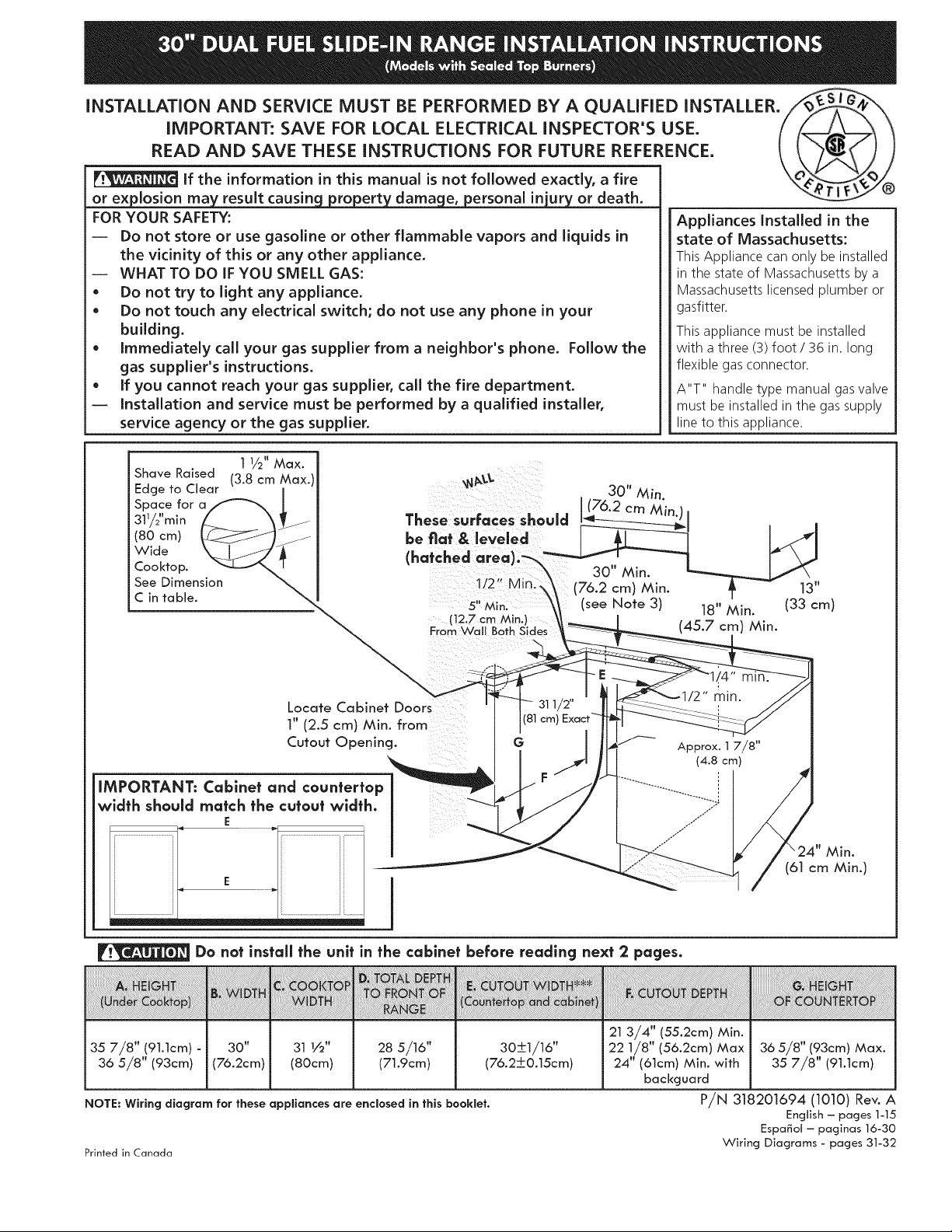
1 1/2" Max.
Shave Raised (3.8 cm Max.)
Edge to Clear
Space for a
311/2"min
(80 cm)
Wide
Cooktop.
See Dimension
C in table.
These surfaces should
be fiat & leveled
(hatched area)."-_
5" Min.
(12.7 cm Min.)
From Wall Both Sides
30" Min.
(76.2 cm Min.)
(see Note 3) 18" Min. (33 cm)
Appliances Installed in the
state of Massachusetts:
This Appliance can only be installed
in the state of Massachusetts by a
Massachusetts licensed plumber or
gasfitter.
This appliance must be installed
with a three (3) foot / 36 in. long
flexible gas connector.
A"T" handle type manual gas valve
must be installed in the gas supply
line to this appliance.
13 vw
(45.7 cm) Min.
Locate Cabinet Doors
1" (2.5 cm) Min. from
Cutout Opening.
IMPORTANT: Cabinet and countertop
width should match the cutout width.
E
I
Do nat install the unit in the cabinet before reading next 2 pages.
35 7/8" (9].]cm) - 30" 31 1/2" 28 5/16" 30_+1/16"
36 5/8" (93cm) (76.2cm) (80cm) (71.9cm) (76.2-I-0.15cm)
NOTE: Wiring diagram for these appliances are enclosed in this booklet.
Printed in Canada
Min.
(61 cm Min.)
21 3/4" (55.2cm) Min.
i 22 1/8" (56.2cm) Max 36 5/8" (93cm) Max.
24" (61cm) Min. with 35 7/8" (91.1cm)
backguard
P/N 318201694 (1010) Rev. A
English - pages 1-15
Espa_ol - paginas 16-30
Wiring Diagrams - pages 31-32
Page 2
NOTES:
Do not pinch the power supply cord between the range and the wall.
Do not seal the range to the side cabinets.
24" (61 cm) minimum clearance between the cooktop and the bottom of the cabinet when the
bottom of wood or metal cabinet is protected by not less than 1/4" (0.64 cm) flame retardant
millboard covered with not less than No. 28 MSG sheet metal, 0.015" (0.4 mm) stainless steel,
0
0.024" (0.6 mm) aluminum, or 0.020" (0.5 mm) copper.
30" (76.2 cm) minimum clearance when the cabinet is unprotected.
For cutouts below 22 7/8"(58.1 cm), appliance will slightly show out of the cabinet.
Allow at least 20" (50.8 cm) clearance for door depth when it is open.
22 7/8" (58.1 cm) min.
23 1/4" (59.05 cm) max.
.__ 11/8"
(2.86 cm)
FRONT /
OF _ }::Ref. 1
CABINET
m
A
Side Panel
35 7/8" (91.1cm)
36 5/8" (93cm)
30"
(76.2cm)
31 I/2"
(80cm)
28 5/16" (71.9cm) 30___I/16"
(76,2+0,15crn)
21 3/4" (55.2cm) Min.
22 1/8" (56.2cm) Max
24" (61cm) Min. with
backguard
36 5/8" (93cm)
Max.
35 7/8" (91.1cm)
Page 3
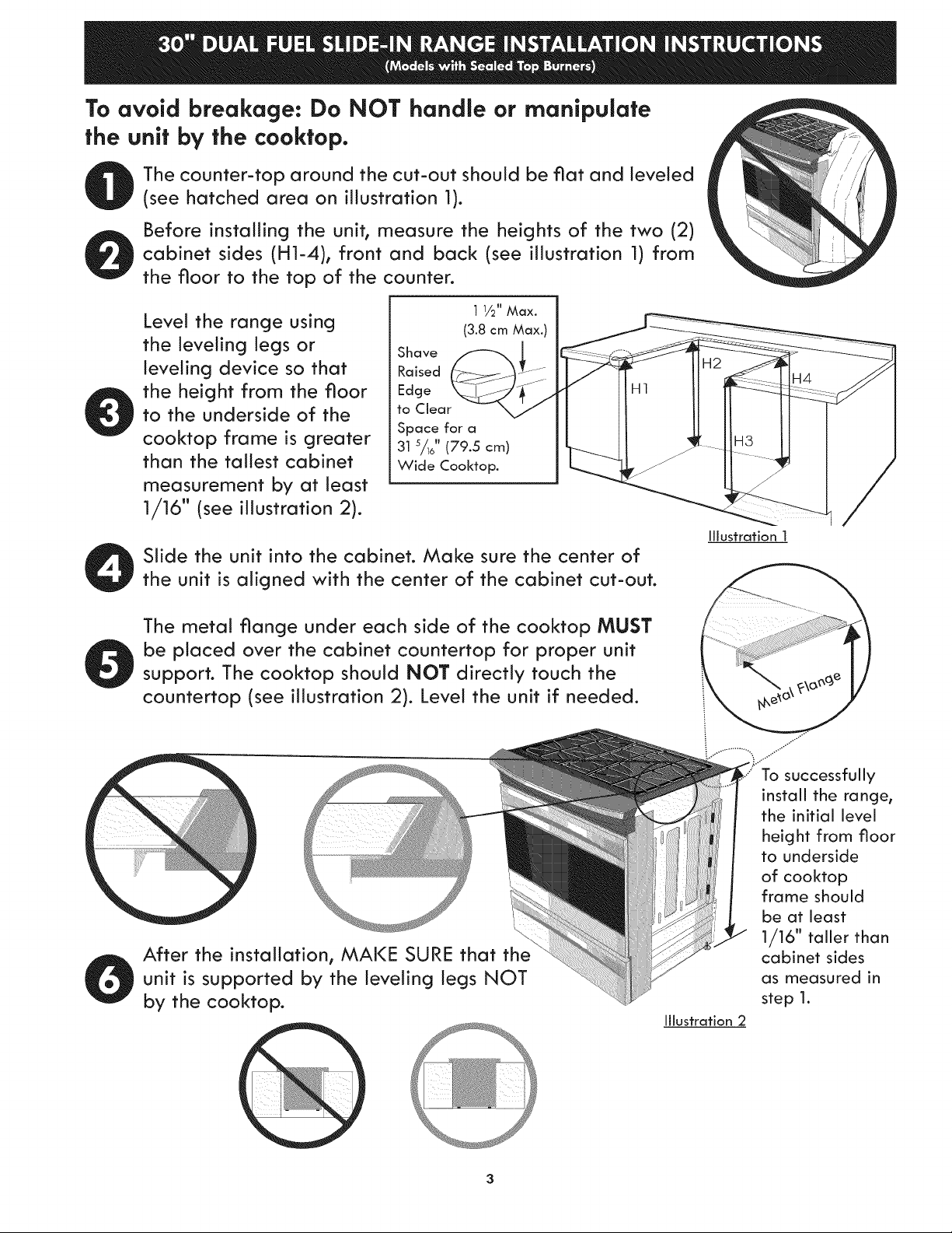
To avoid breakage: Do NOT handle or manipulate
the unit by the cooktop.
The counter-top around the cut-out should be fiat and leveled
(see hatched area on illustration 1).
Before installing the unit, measure the heights of the two (2)
cabinet sides (H1-4), front and back (see illustration 1) from
the floor to the top of the counter.
Level the range using
the leveling legs or
leveling device so that
the height from the floor
to the underside of the
cooktop frame is greater
than the tallest cabinet
measurement by at least
1/16" (see illustration 2).
Slide the unit into the cabinet. Make sure the center of
the unit is aligned with the center of the cabinet cut-out.
Shave _
Raised
Edge
to Clear
Space for a
31 s/1J' (79.5 cm) I__
Wide Cooktop.
H1
/
Illustration 1
The metal flange under each side of the cooktop MUST
be placed over the cabinet countertop for proper unit
support. The cooktop should NOT directly touch the
countertop (see illustration 2). Level the unit if needed.
After the installation, MAKE SURE that the
unit is supported by the leveling legs NOT
by the cooktop.
j..."
To successfully
install the range,
the initial level
height from floor
to underside
of cooktop
frame should
be at least
1/16" taller than
cabinet sides
as measured in
step 1.
Illustration 2
3
Page 4
important Notes to the installer
1. Read all instructions contained in these
installation instructions before installing range.
2. Remove all packing material from the oven
compartments before connecting the gas and
electrical supply to the range.
3. Observe all governing codes and ordinances.
4. Be sure to leave these instructions with the
consumer.
.
Note: For operation at 2000 ft. elevations
above see level, appliance rating shall be
reduced by 4 percent for each additional
1000 ft.
important Nofe fo fhe Consumer
Keep these instructions with your Use & Care
Guide for future reference.
iMPORTANT SAFETY
iNSTRUCTiONS
Installation of this range must conform with
local codes or, in the absence of local codes,
with the National Fuel Gas Code ANSi Z223.1/
NFPA .54-latest edition.
This range has been design certified by CSA
International. As with any appliance using
gas and generating heat, there are certain
safety precautions you should follow. You will
find them in the Use and Care Guide, read it
carefully.
* Be sure your range is installed and grounded
properly by a qualified installer or service
technician.
* This range must be electrically grounded
in accordance with local codes or, in their
absence, with the National Electrical Code
ANSI/NEPA No. 70--latest edition. See
Grounding Instructions.
* Before installing the range in an area
covered with linoleum or any other synthetic
floor covering, make sure the floor covering
can withstand heat at least 90°F above
room temperature without shrinking,
warping or discoloring. Do not install the
range over carpeting unless you place an
insulating pad or sheet of 1/_" (10,16 cm) thick
plywood between the range and carpeting.
* Make sure the wall coverings around the
range can withstand the heat generated by
the range.
* Do not obstruct the flow of combustion air
at the oven vent nor around the base or
beneath the lower front panel of the range.
Avoid touching the vent openings or nearby
surfaces as they may become hot while the
oven is in operation. This range requires fresh
air for proper burner combustion.
Never leave children alone or
unattended in the area where an appliance
is in use. As children grow, teach them the
proper, safe use of all appliances. Never
leave the oven door open when the range is
unattended.
Stepping, leaning or sitting on the
doors or drawers of this range can result in
serious injuries and can also cause damage to
the range.
* Do not store items of interest to children in
the cabinets above the range. Children could
be seriously burned climbing on the range to
reach items.
* To eliminate the need to reach over the
surface burners, cabinet storage space
above the burners should be avoided.
* Adjust surface burner flame size so it does
not extend beyond the edge of the cooking
utensil. Excessive flame is hazardous.
* Do not use the oven as a storage space. This
creates a potentially hazardous situation.
* Never use your range for warming or
heating the room. Prolonged use of the
range without adequate ventilation can be
dangerous.
* Do not store or use gasoline or other
flammable vapors and liquids near this or
any other appliance. Explosions or fires could
result.
* In the event of an electrical power outage,
the surface burners can be lit manually. To
light a surface burner, hold a lit match to
the burner head and slowly turn the Surface
Control knob to LITE. Use caution when
lighting surface burners manually.
" Reset all controls to the "off" position after
using a programmable timing operation.
FOR MODELS WITH SELF-CLEAN FEATURE:
* Remove broiler pan, food and other utensils
before self-cleaning the oven. Wipe up
excess spillage. Follow the precleaning
instructions in the Use and Care Guide.
* Unlike the standard gas range, THIS
COOKTOP IS NOT REMOVABLE. Do not
attempt to remove the cooktop.
Page 5
Before Starting
Tools you will need
For leveling legs and anfl-tip brackets: _-._ _"_,_i-\,
• Adjustable wrench or channel lock pliers ......._s_ ....
• 5/16" Nutdriver or Flat Head Screw Driver
• Electric Drill & 1/8 Diameter _
Drill Bit (5/32" Masonry Drill
Bit if installing in concrete)
• Level & Measuring Tape
For gas supply connection:
• Pipe Wrench i_
• Brush
For burner flame adjustment:
• Phillips head _ and blade-type _o
screwdrivers
For gas conversion (LP/Propane or Natural):
• Open end wrench - 1/2" _
3I_/2".._
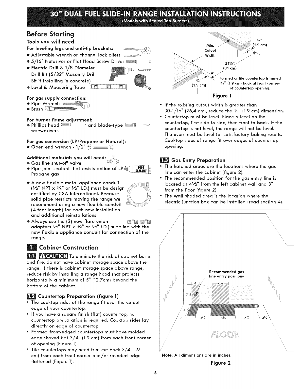
(81 cm)
Formed or tile countertop trimmed
¾" (1.9 cm) back at front corners
of countertop opening.
Figure 1
If the existing cutout width is greater than
30-1/16" (76,4 cm), reduce the 3¼" (1.9 cm) dimension.
Countertop must be level. Place a level on the
countertop, first side to side, then front to back. If the
countertop is not level, the range wiii not be level.
The oven must be level for satisfactory baking results.
Cooktop sides of range fit over edges of countertop
opening.
Additional materials you will need: _
• Gas line shut-off valve
• Pipe joint sealant that resists action of LP/_'---PfM_
Propane gas .............
• A new flexible metal appliance conduit
(_,,_"NPT x 3/4" or _,,_" I.D.) must be design
certified by CSA International. Because
solid pipe restricts moving the range we
recommend using a new flexible conduit
(4 feet length) for each new installation
and additional reinstallations.
• Always use the (2) new flare union
adapters _,'_" NPT x 3/4" or _,_" I.D.) supplied with the
new flexible appliance conduit for connection of the
range.
Cabinet Construction
_ To eliminate the risk of cabinet burns
and fire, do not have cabinet storage space above the
range. If there is cabinet storage space above range,
reduce risk by installing a range hood that projects
horizontally a minimum of 5" (12.7cm) beyond the
bottom of the cabinet.
| Caunferfop Preparation (figure 1)
° The cooktop sides of the range fit over the cutout
edge of your countertop.
° If you have a square finish [fiat) countertop, no
countertop preparation is required. Cooktop sides lay
directly on edge of countertop.
° Formed front-edged countertops must have molded
edge shaved fiat 3/4" (1.9 cm) from each front corner
of opening (Figure I).
° Tile countertops may need trim cut back 3/4"(1.9
cm) from each front corner and/or rounded edge
flattened [Figure 1).
Gas Entry Preparation
° The hatched areas are the locations where the gas
line can enter the cabinet [figure 2).
° The recommended position for the gas entry line is
located at 41/_'' from the left cabinet wall and 3"
from the floor [figure 2).
° The wall shaded area is the location where the
electric junction box can be installed [read section 4).
Recommended gas
llne entry posfflons
\
\
/
/
iiiii_ii
//
/
Note: All dimensions are in inches.
Figure 2
\
....._i!ii
\
\, i
Page 6
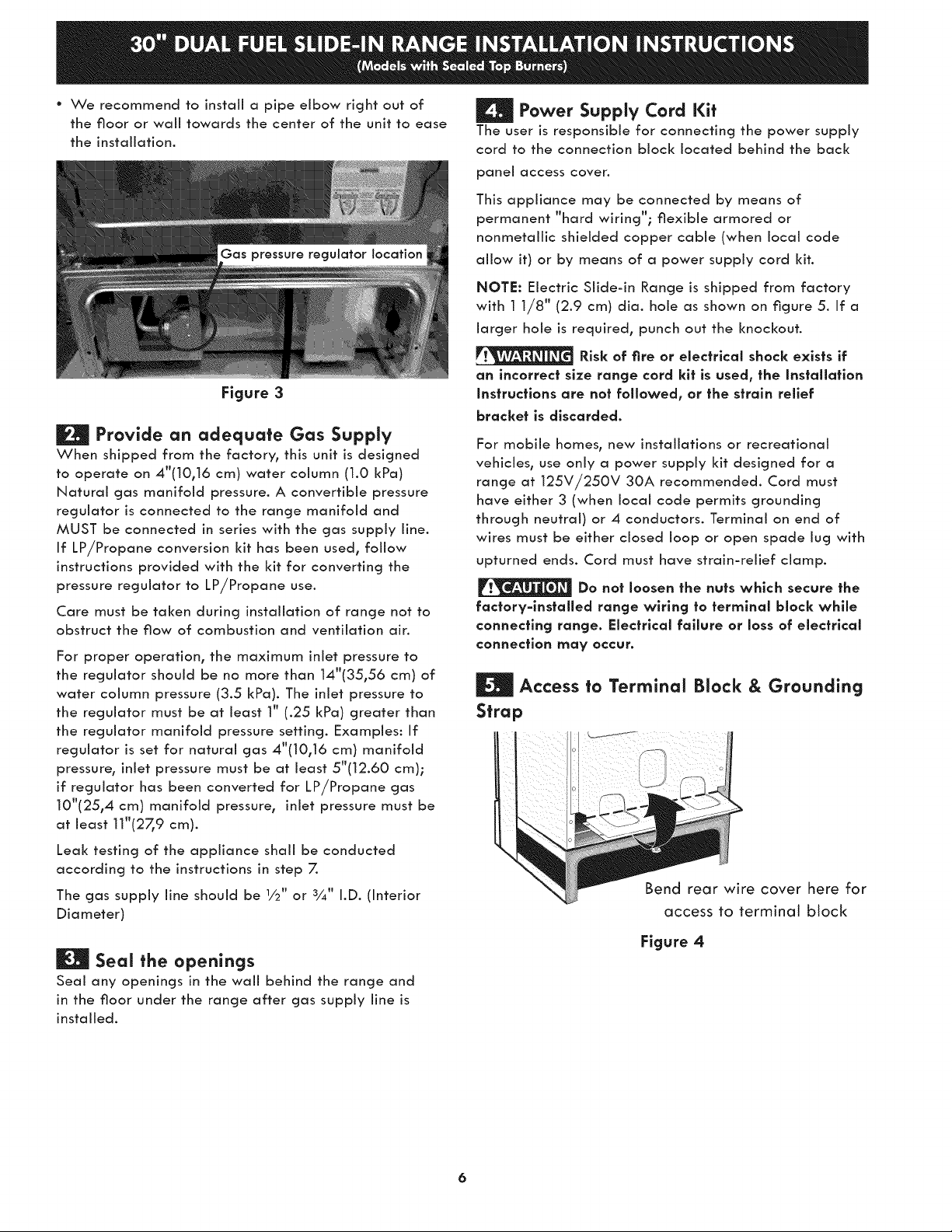
° We recommend to install a pipe elbow right out of
the floor or wail towards the center of the unit to ease
the installation.
Figure 3
H Provide an adequate Gas Supply
When shipped from the factory, this unit is designed
to operate on 4"(10,16 cm) water column (1.0 kPa)
Natural gas manifold pressure. A convertible pressure
regulator is connected to the range manifold and
MUST be connected in series with the gas supply line.
If LP/Propane conversion kit has been used, follow
instructions provided with the kit for converting the
pressure regulator to LP/Propane use.
Care must be taken during installation of range not to
obstruct the flow of combustion and ventilation ain
For proper operation, the maximum inlet pressure to
the regulator should be no more than 14"(35,56 cm) of
water column pressure (3.5 kPa). The inlet pressure to
the regulator must be at least 1" (.25 kPa) greater than
the regulator manifold pressure setting. Examples: If
regulator is set for natural gas 4"(10,16 cm) manifold
pressure, inlet pressure must be at least 5"(12.60 cm);
if regulator has been converted for LP/Propane gas
10"(25,4 cm) manifold pressure, inlet pressure must be
at least 11"(27_9 cm).
Leak testing of the appliance shall be conducted
according to the instructions in step 7.
The gas supply line should be 1/2" or 3¼" I.D. (Interior
Diameter)
Power Supply Cord Kit
The user is responsible for connecting the power supply
cord to the connection block located behind the back
paneJ access cover.
This appliance may be connected by means of
permanent "hard wiring"; flexible armored or
nonmetallic shielded copper cable (when local code
allow it) or by means of a power supply cord kit.
NOTE: Electric Slide-in Range is shipped from factory
with 1 1/8" (2.9 cm) dia. hole as shown on figure 5. If a
larger hole is required, punch out the knockout.
Risk of fire or electrical shock exists if
an incorrect size range cord kit is used, the Installatlon
instructions are not followed, or the strain relief
bracket is discarded.
For mobile homes, new installations or recreational
vehicles, use only a power supply kit designed for a
range at 125V/250V 30A recommended. Cord must
have either 3 (when local code permits grounding
through neutral) or 4 conductors. Terminal on end of
wires must be either closed loop or open spade Jug with
upturned ends. Cord must have strain-relief clamp.
Do not loosen the nuts which secure the
factory=installed range wiring to termlnal block while
connecting range. Electrical failure or loss of electrical
connection may occur.
Access to Terminal Block & Grounding
Strap
Bend rear wire cover here for
access to terminal block
| Seal the openings
Seal any openings in the wall behind the range and
in the floor under the range after gas supply line is
installed.
Figure 4
Page 7
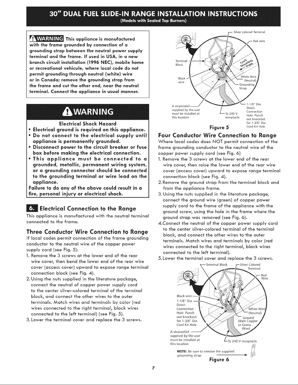
This appliance is manufactured
with the frame grounded by connection of a
grounding strap between the neutral power supply
terminal and the frame. If used in USA, in a new
branch circuit installation (1996 NEC), mobile home
or recreational vehlcule, where local code do not
permit grounding through neutral (white) wire
or in Canada; remove the grounding strap from
the frame and cut the other end, near the neutral
terminal. Connect the appliance in usual manner.
Terminal
Block
wire
Silver colored Terminal
wi re
Electrical Shock Hazard
• Electrlcal ground is required on this appliance.
• Do not connect to the electrical supply until
appliance is permanently grounded.
• Disconnect power to the circuit breaker or fuse
box before making the electrical connection.
• This appllance must be connected to a
grounded, metallic, permanent wiring system,
or a grounding connector should be connected
to the grounding terrnlnal or wire lead on the
appffance.
Failure to do any of the above could resuff in a
fire, personal injury or electrical shock.
Electrical Connection to the Range
This appliance is manufactured with the neutral terminal
connected to the frame.
Three Conductor Wire Connection to Range
If local codes permit connection of the frame grounding
conductor to the neutral wire of the copper power
supply cord (see Fig. 5):
1. Remove the 3 screws at the lower end of the rear
wire cover, then bend the lower end of the rear wire
cover (access cover) upward to expose range terminal
connection block (see Fig. 4).
2. Using the nuts supplied in the literature package,
connect the neutral of copper power supply cord
to the center silver-colored terminal of the terminal
block, and connect the other wires to the outer
terminals. Match wires and terminals by color (red
wires connected to the right terminal, black wires
connected to the Jeff terminal) (see Fig. 5).
3. Lower the terminal cover and replace the 3 screws.
A strainrelief-- Direct
supplied by the user Connection
must be installed at To 240 V
this location receptacle out knockout
1-1/8" Dia.
Hole. Punch
for 1-3/8" Dia.
Figure 5 CordKitHole
Four Conductor Wire Connection to Range
Where local codes does NOT permit connection of the
frame grounding conductor to the neutral wire of the
copper power supply cord (see Fig. 6)
1. Remove the 3 screws at the lower end of the rear
wire coveb then raise the lower end of the rear wire
cover (access cover) upward to expose range terminal
connection block (see Fig. 4).
2. Remove the ground strap from the terminal block and
from the appliance frame.
3. Using the nuts supplied in the literature package,
connect the ground wire (green) of copper power
supply cord to the frame of the appliance with the
ground screw, using the hole in the frame where the
ground strap was removed (see Fig. 6).
4.Connect the neutral of the copper power supply cord
to the center silver-colored terminal of the terminal
block, and connect the other wires to the outer
terminals. Match wires and terminals by color (red
wires connected to the right terminal, black wires
connected to the left terminal).
5. Lower the terminal cover and replace the 3 screws.
] Terminal
1-1/8"
Direct
Connection
Hole. Punch
out knockout
for 1-3/8" Dia.
Cord Kit Hol{
A strainretief
supplied by the user
must be installed at
this location
NOTE: Be sure to remove the supplied
grounding strap
7
Btock Colored
240 V receptacle
Figure 6
Wire
Page 8
Direct Electrical Connection to the Circuit
Breaker, Fuse Box or Junction Box
If the appliance is connected directly to the circuit
breaker, fuse box or junction box, use flexible, armored
or nonmetallic sheathed copper cable (with grounding
wire). Supply a U.L. listed strain-relief at each end
of the cable. At the appliance end, the cable goes
through the Direct Connection Hole (see Figure 6) on
the Cord Mounting Plate. Wire sizes (copper wire only)
and connections must conform to the rating of the
appliance.
Where local codes permit connecting the
appliance-grounding conductor to the
neutral (white) wire (see Figure 7):
1. Be sure that no power is supplied on the cable from
residence.
2. Remove the grounding strop from the terminal block
and from the appliance frame.
3. In the circuit breaker, fuse box or junction box:
A) Connect the green (or bare copper) wire, the
white appliance cable wire, and the neutral (white)
wire together.
B) Connect the 2 black wires together.
C) Connect the 2 red wires together.
Where local codes DO NOT permit
connecting the appliance-grounding
conductor to the neutral (white) wire, or if
connecting to 4-wire electrical system (see
Figure 8):
1. Be sure that no power is supplied on the cable from
residence.
2. Remove the grounding strap from the terminal block
and from the appliance frame.
3. In the circuit breaker, fuse box or junction box:
A) Connect the white appliance cable wire to the
neutral (white) wire.
B) Connect the 2 black wires together.
C) Connect the 2 red wires together.
D) Connect the green (or bare copper) grounding
wire to the grounding wire of the circuit breaker, fuse
box or junction box.
Cable from
Green
(or Bare Copper)
Residence Junction
Box
_ _hietetrWaill e
Cable from
White Wire
(Neutral) P"h Black
Red ;;
Wires
Green -- U..qsted
(or Bare Copper) Conduit
Wire CabJe from Connector
Residence
..................::.: i le
Range (or CSA listed)
Figure 7
3-Wire (Grounded Neutral) Electrical System
(Example: Junction Box)
Wires
Green
(or Bare Copper)
_% ____White wire
Wire
Cable from Conduit
Appliance Connector
Figure 8 - 4-Wire Electrlcal System
(Example: Junction Box)
(or CSA listed)
Page 9
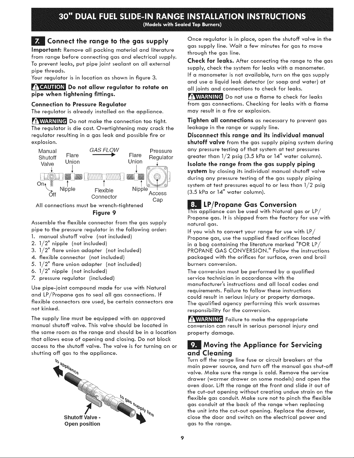
| Connect the range to the gas supply
Impartant: Remove all packing material and literature
from range before connecting gas and electrical supply.
To prevent teaks, put pipe joint sealant on aii external
pipe threads.
Your regulator is in location as shown in figure 3.
Do not allow regulator to rotate an
pipe when tightening fittings.
Connection to Pressure Regulator
The regulator is already installed on the appliance.
Do not make the connection too tight.
The regulator is die cast. Overtightening may crack the
regulator resulting in a gas leak and possible fire or
explosion.
Manual GAS FLOW Pressure
Shutoff Flare _" Flare Regulator
Valve Union Union
Nipple Flexible NJpple_
Off Connector
All connections must be wrench-tightened
Figure 9
Assemble the flexible connector from the gas supply
pipe to the pressure regulator in the following order:
1. manual shutoff valve (not included)
2. 1/2" nipple (not included)
3. 1/2" flare union adapter (not included)
4. flexible connector (not included)
5. 1/2" flare union adapter (not included)
6. 1/2" nipple (not included)
7. pressure regulator (included)
Use pipe-joint compound made for use with Natural
and LP/Propane gas to seal all gas connections. If
flexible connectors are used, be certain connectors are
not kinked.
The supply line must be equipped with an approved
manual shutoff valve. This valve should be located in
the same room as the range and should be in a location
that allows ease of opening and closing. Do not block
access to the shutoff valve. The valve is for turning on or
shutting off gas to the appliance.
t_
Shutoff Valve =
Open position
Access
Cap
Once regulator is in place, open the shutoff valve in the
gas supply line. Wait a few minutes for gas to move
through the gas line.
Check far leaks. After connecting the range to the gas
supply, check the system for leaks with a manometen
If a manometer is not available, turn on the gas supply
and use a liquid leak detector (or soap and water) at
all joints and connections to check for leaks.
Do not use a flame to check for leaks
from gas connections. Checking for leaks with a flame
may result in a fire or explosion.
Tighten all connections as necessary to prevent gas
leakage in the range or supply line.
Disconnect this range and its individual manual
shutoff valve from the gas supply piping system during
any pressure testing of that system at test pressures
greater than 1/2 psig (3.5 kPa or 14" water column).
Isolate the range from the gas supply piping
system by closing its individual manual shutoff valve
during any pressure testing of the gas supply piping
system at test pressures equal to or less than 1/2 psig
(3.5 kPa or 14" water column).
LP/Propane Gas Conversion
This appliance can be used with Natural gas or LP/
Propane gas. It is shipped from the factory for use with
natural gas.
If you wish to convert your range for use with LP/
Propane gas, use the supplied fixed orifices located
in a bag containing the literature marked "FOR LP/
PROPANE GAS CONVERSION." Follow the instructions
pad<aged with the orifices for surface, oven and broil
burners conversion.
The conversion must be performed by a qualified
service technician in accordance with the
manufacturer's instructions and all local codes and
requirements. Failure to follow these instructions
could result in serious injury or property damage.
The qualified agency performing this work assumes
responsibility for the conversion.
Failure to make the appropriate
conversion can result in serious personal injury and
property damage.
Moving the Appliance for Servicing
and Cleaning
Turn off the range line fuse or circuit breakers at the
main power source, and turn off the manual gas shut-off
valve. Make sure the range is cold. Remove the service
drawer (warmer drawer on some models) and open the
oven door. Lift the range at the front and slide it out of
the cut-out opening without creating undue strain on the
flexible gas conduit. Make sure not to pinch the flexible
gas conduit at the back of the range when replacing
the unit into the cut-out opening. Replace the drawer,
close the door and switch on the electrical power and
gas to the range.
9
Page 10
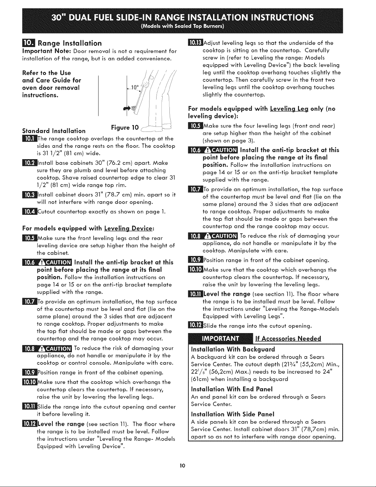
Range installation
Important Note: Door removal is not a requirement for
installation of the range, but is an added convenience.
Refer to the Use
and Core Guide for
oven door removal
instructions.
Standard Installatlon Figure 10
_The range cooktop overlaps the countertop at the
sides and the range rests on the floor. The cooktop
is 31 1/2" (81 cm} wide.
_llnstall base cabinets 30" (76.2 cm) apart. Make
sure they are plumb and level before attaching
cooktop. Shave raised countertop edge to dear 31
1/2" (81 cm) wide range top rim.
|Install cabinet doors 31" (78.7 cm) rain. apart so it
will not interfere with range door opening.
_L_Cutout countertop exactly as shown on page 1.
For models equipped with Leveling Device:
|Make sure the front leveling legs and the rear
leveling device are setup higher than the height of
the cabinet.
Install the anti-tlp bracket at this
point before placing the range at its final
position. Follow the installation instructions on
page 14 or 15 or on the anti-tip bracket template
supplied with the range.
_F_To provide an optimum installation, the top surface
of the countertop must be level and flat (lie on the
same plane) around the 3 sides that are adjacent
to range cooktop. Proper adjustments to make
the top flat should be made or gaps between the
countertop and the range cooktop may occur.
To reduce the risk of damaging your
appliance, do not handle or manipulate it by the
cooktop or control console. Manipulate with care.
_Position range in front of the cabinet opening.
_Make sure that the cooktop which overhangs the
countertop dears the countertop. If necessary,
raise the unit by lowering the leveling legs.
|Slide the range into the cutout opening and center
it before leveling it.
|Level the range (see section 11). The floor where
the range is to be installed must be level. Follow
the instructions under "Leveling the Range- Models
Equipped with Leveling Device".
|Adjust leveling legs so that the underside of the
cooktop is sitting on the countertop. Carefully
screw in (refer to Leveling the range: Models
equipped with Leveling Device") the back ieveling
leg until the cooktop overhang touches slightly the
countertop. Then carefully screw in the front two
leveling legs until the cooktop overhang touches
slightly the countertop.
Far models equipped with Leveling Leg only (no
leveling device):
|Make sure the four leveling legs (front and rear)
are setup higher than the height of the cabinet
(shown on page 3).
Install the anti-tlp bracket at this
point before placing the range at its final
position. Follow the installation instructions on
page 14 or 15 or on the anti-tip bracket template
supplied with the range.
_To provide an optimum installation, the top surface
of the countertop must be level and flat (lie on the
same plane) around the 3 sides that are adjacent
to range cooktop. Proper adjustments to make
the top flat should be made or gaps between the
countertop and the range cooktop may occur.
To reduce the risk of damaging your
appliance, do not handle or manipulate it by the
cooktop. Manipulate with care.
_'_Position range in front of the cabinet opening.
_Make sure that the cooktop which overhangs the
countertop clears the countertop. If necessary,
raise the unit by lowering the ieveling legs.
_"[_i[_Levei the range (see section 11). The floor where
the range is to be installed must be level. Follow
the instructions under "Leveling the Range-Models
Equipped with Leveling Legs".
|Slide the range into the cutout opening.
lf Accessories Needed
Installatlon With Backguard
A backguard kit can be ordered through a Sears
Service Center. The cutout depth (213¼" (55,2cm) Min.,
221/8 '' (56,2cm) Max.) needs to be increased to 24"
(61cm) when installing a backguard
Installation With End Panel
An end panel kit can be ordered through a Sears
Service Center.
Installation With Side Panel
A side panels kit can be ordered through a Sears
Service Center. Install cabinet doors 31" (78,7cm) min.
apart so as not to interfere with range door opening.
10
Page 11

Levelincj the Rancje
ModeJs Equipped with LeveJlng Device
Level the range after installation in the cutout
opening.
1. Open the range drawer. The leveling screws control
the height of the rear leg.
2. Adjust the appliance legs as follows until the
underside of the cooktop (or cooktop glass) surface
is sitting level on the countertop (Figure 11).
a.To adjust the front legs0 use a wrench on the
leg base and turn counterclockwise to lower or
clockwise to raise the range.
b.To adjust the rear legs_ use a ratchet or
a nutdriver and turn the leveling screws
counterclockwise to lower or clockwise to raise
the range.
3. Check if the range is level by installing an oven rack
in the center of the oven and placing a level on the
rack (Figure 12).
4. Take 2 readings with the level placed diagonally in
one direction and then the other. Level the range° if
necessary_ by adjusting the leveling legs.
5. If the range cannot be JeveJ_contact a carpenter to
correct sagging or sloping floor.
Models Equipped with Levelin_
Level the range and set cooktop height before
installation in the cut-out opening.
1. Install an oven rack in the center of the oven.
2. Place a level on the rack (see Figure 12). Take 2
readings with the level placed diagonally in one
direction and then the other. Level the range_ if
necessary_ by adjusting the 4 leg levelers with a
wrench (see Figure 20).
3. Taking care to not damage the countertop, slide
range into cutout opening and double check for
levelness. ........ ....
@
i
J
i
Levellnl
Front
Leveilng
Leg
1. Disconnect the power from the range.
2. Make sure the range is leveled.
3. Pull range toward you.
4. Measure the distance between the floor and the
surface underneath the cooktop frame.
5. Marl< that distance on the wall where the decorative
trim will be installed.
6. Draw a line.
Z Place the top of the decorative trim under that line.
8. Using the screws provided fix the decorative trim
into the wall.
9. Slide the range back into position as far as it will
go and reconnect the power source.
Trim
LOWER
RAISE
Figure 11
11
Figure 13
Page 12

Check Operation
Refer to the Use and Care Guide packaged with the
range for operating instructions and for care and
cleaning of your range.
Remove all packaging from the oven before testing.
_[_ install Burner Bases and Burner Caps
This range is equipped with sealed burners as
shown (see Figure 14).
a. Unpack burner bases and
burner caps.
b. Place burner bases over
each gas opening.
c. Make sure the burner
is properly aligned and
leveled. Place burner caps
over appropriate burner
bases.
NOTE: There are no burner
adjustments necessary on this
range.
Turn an Electrical Power and Open Main
Shutoff Gas Valve
Check the igniters
Operation of electric igniters should be checked after
range and supply line connectors have been carefully
checked for leaks, and range has been connected to
electric power. To check for proper lighting:
a.Push in and turn a surface burner knob to the LITE
position. You will hear the igniter sparking.
b. The surface burner should light when gas is available
to the top burner. Each burner should light within four
(4) seconds after air has been purged from supply
lines. Visually check that burner has lit.
c. Once the burner lights, the control knob should be
rotated out of the LITE position.
There are separate ignition devices for each burner. Try
each knob separately until all burner valves have been
checked.
J
Electrode
Figure 14
the slotted screw inside. Flame size can be increased
or decreased with the turn of the screw. Adjust
flame until you can quickly turn knob from HI to
LOWEST POSITION without extinguishing the flame.
Flame should be as small as possible and stable
without going out.
.
Repeat the steps from 1to 4 until all the burners
operate properJ .
Hollow Valve
Stem
Figure 15
Adjust the "LOW" Setting of the Dual Valve
(Fig. 16)
Note: On the dual valve the low setting of each portion
should be adjusted individually.
a. Push in and turn control to LITE until the rear portion
of the bridge burner ignites only.
b. Qulcklv turn knob to LOWEST POSITION.
c. If burner goes out, reset control to OFF.
d. Remove the surface burner control knob.
e. The rear portion of the bridge burner flame size can
be increased or decreased with the turn of the screw
A. Use screw B to adjust the flame size of the center
portion of the bridge burner. Turn counterclockwise
the screw to increase flame size. Turn clockwise the
screw to decrease flame size. Adjust flame until
you can quickly turn knob from LITE to LOWEST
POSITION without extinguishing the flame. Flame
should be as small as possible without going out.
Note: Air mixture adjustment is not required on surface
burners.
Adjust the "LOW" Setting of Surface Burner
Valves (linear flow and three position valves) (Fig
15)
Adjust "LO" setting as follows:
1. Let appliance cool down to room temperature.
2. Light up all burners by turning each control knob to
LITE until all burners ignite and set them at HI.
3. Quickly turn down the burner involved from HI to
LOWEST SETTING.
4. If burner goes out, readjust valve as follows:
Remove the burner control knob, insert a thin-blade
screwdriver into the hollow valve stem and engage
: \}
Figure 16
12
Page 13

When All Hookups are Complete
Make sure all controls are left in the OFF position.
Make sure the flow of combustion and ventilation air to
the range is unobstructed.
Model and Serial Number Location
The serial plate is located on the oven front frame
behind the oven door (some models) or on the drawer
side frame (some models).
When ordering parts for or making inquiries about your
range, always be sure to include the model and serial
numbers and a lot number or letter from the serial plate
on your range.
Your serial plate also tells you the rating of the burners,
the type of fuel and the pressure the range was
adjusted for when it left the factory.
Before You Call for Service
Read the Before You Call Checklist and operating
instructions in your Use and Care Guide. It may save
you time and expense. The list includes common
occurrences that are not the result of defective
workmanship or materials in this appliance.
Refer to your Use & Care Guide for Sears service phone
numbers or call 1-800-4-MY-HOME®.
13
Page 14

| Anti-Tip Brackets Installation
Instructions
Models Equipped with Leveling Device
To reduce the risk of tipping of the range,
the range must be secured to the floor by properly
installed anti-tip bracket and screws packed with the
range. These parts are located in the oven. Failure to
install the anti-tip bracket will allow the range to tip over
if excessive weight is placed on an open door or if a child
climbs upon it. Serious injury might result from spilled hot
liquids or from the range itself.
Follow the instructions below to install the anti-tip
brackets.
If range is ever moved to a different location, the anti-
tip brackets must also be moved and installed with the
range.
Tools Required:
Adjustable Wrench
Ratchet
Drill & 1/8"(0,32 cm) bit
5/16" (0,8 cm) Nutdriver
Level
The anti-tip bracket attaches to the floor at the back of
the range to prevent range from tipping. When fastening
bracket to the floor, be sure that screws do not penetrate
electrical wiring or plumbing. The screws provided will
work in either wood or concrete.
1. Draw a center line (CL) on the floor where the range
should be installed. Also draw a line on the floor at
the range back position if there is no wall.
2. Unfold paper template and place it fiat on the floor
with the right rear corner positioned exactly on the
intersection of the center and back lines you just drew
before. (Use the diagram below to locate brackets if
template is not available (Figure 17)).
3. Mark on the floor the location of the 4 mounting
holes shown on the template. For easier installation,
3/16"(0,48 cm) diameter pilot holes 1/2"(1,27 cm)
deep can be drilled into the floor.
4. Remove template and place bracket on floor. Line up
holes in bracket with marks on floor and attach with
4 screws provided. Bracket must be secured to solid
floor (Figure 20). If attaching to concrete floor, first
drill 3/16"(0,48 cm) dia. pilot holes using masonry drill
bit.
5. Be sure the 4 leveling legs are at the highest position
they can be.
6. Slide range into place making sure structure of the
range is trapped by the anti-tip bracket (Figure 18).
Lower the range by adjusting the 4 leveling legs until
the underside of the cooktop is sitting level on the
countertop. Refer to "Leveling the Range" section.
7. After installation, verify that the anti-tip bracket is
engaged by grasping the top rear edge of the range
and carefully attempt to tilt it forward to make sure
range is properly anchored.
H
(CL : Center line)
Door
Cabinet
Floor Me
Screws
Figure 18
_LIDE
BACK
Figure 17
14
Page 15

| Models Equipped with Leveling iec_
To reduce the risk of tipping of the range,
the range must be secured to the floor by properly
installed anti-tip brackets and screws packed with the
range. These parts are located in a plastic bag in the
oven. Failure to install the anti-tip brackets wiii allow
the range to tip over if excessive weight is placed on
an open door or if a child climbs upon it. Serious injury
might result from spilled hot liquids or from the range
itself.
Follow the instructions below to install the anti-tip
brackets.
If range is ever moved to a different location, the anti-
tip brackets must also be moved and installed with the
range. To check for proper installation, see step 5.
Tools Required:
5/16" (0,79 cm) Nutdriver or Flat Head Screwdriver
Adjustable Wrench
Electric Drill
3/16"(0,5 cm) Diameter Drill Bit
3/16"(0,5 cm) Diameter Masonry Drill Bit (if installing in
concrete)
Brackets attach to the floor at the back of the range to
hold both rear leg levelers. When fastening to the floor,
be sure that screws do not penetrate electrical wiring or
plumbing. The screws provided will work in either wood
or concrete.
1. Unfold paper template and place it flat on the floor
with the back and side edges positioned exactly
where the back and sides of range will be located
when installed. (Use the diagram below to locate
brackets if template is not available. (Figure 19))
2. Mark on the floor the location of the 4 mounting
holes shown on the template. For easier installation,
3/16" (0.5 cm) diameter pilot holes 1/2" (1.3 cm)
deep can be drilled into the floor.
3. Remove template and place brackets on floor
with turned up flange to the front. Line up holes
in brackets with marks on floor and attach with 4
screws provided. Brackets must be secured to solid
floor. If attaching to concrete floor, first drill 3/16"
(0.5 cm) dia. pilot holes using a masonry drill bit.
4. Level range if necessary, by adjusting 4 leg levelers
with wrench (Figure 20). A minimum clearance of
1/8" (0.8 cm) is required between the bottom of the
range and the rear leg levelers to allow room for
the anti-tip brackets.
5. Slide range into place making sure rear legs are
trapped by ends of brackets. Range may need to
be shifted slightly to one side as it is being pushed
back to allow rear legs to slide under brackets. You
may also grasp the top rear edge of the range and
carefully attempt to flit it forward to make sure
range is properly anchored.
Back Edge of
Range or Rear Wall _ .
i _,(23.2 _1 • (46.4_m)
Anti-Tip _ _ '_ 28 1/8"
Bracket "'. (Rear width of range
(C[ = Cen|er llne)
_--. _..(71.4 cm)
with body sides)
i
Figure 19
ij Anti-Tip Bracket
Slide Back
/
/
/
/
/
<
Leveling Leg
Raise "-.
Lower
Figure 20
15
Page 16

LA INSTALACION Y ELSERVICIODEBENSEREFECTUADOSPORUN INSTALADORCALIFICADO.
JMPORTANTE:GUARDEESTA$INSTRUCCIONESPARAUSO DELINSPECTORLOCALDE ELECTRICIDAD.
LEAY GUARDEESTASJNSTRUCCIONESPARAREFERENCIAFUTURA.
Si la informaci6n contenlda en esfe manual no es seguida
exactamente, puede ocurrir un incendio o explosi6n causando daSos materiales,
lesi6n personal o la rnuerfe.
PARASU SEGURIDAD:
m No almacene nl ufllice gasolina u ofros vapores y liquldos inflarnables en la
pro×imldad de _ste o de cualquler otto artefacto.
QUE DEBEHACER SI PERCIBEOLOR A GAS:
" No frate de encender nlng6n artefacto.
* No toque nlng6n inferruptor el4ctrlco; no use nlng6n fel4fono en su edificlo.
" Llame a su proveedor de gas desde el fel4fono de un veclno. Siga las
instrucclonesdel proveedor de gas.
" Si no Iogra comunlcarsecon su proveedor de gas, Ilame al depa#amento de
bomberos.
La instalaci6n y el servlclode mantenlmlento deben set efectuados pot un
instalador calificado, la agencla de servlclo o el proveedor de gas.
Acepille ei I 1/2" Max.
borde subido (3.8 cm Max.
a que deje
espacio iz _
para un ___.
borde _ J/
1 " j
3172 (80cm_
de anchura de _
estufa. Vea C
en el tablero.
5" Mino
(12.7 cm Min.)
From Wall B
Aparatos Insfalados en el esfado de
Massachusetts;
Este Aparato s61o puede ser instalado
en ei estado de Massachusetts por un
piomero o ajustador de gas licenciado de
Massachusett.
Este aparato se debe instalar con un
iarcjo conector flexible de gas de tres (3)
pies/36 puicjadas.
Una v61vula manual de gas de fipo manija
de forma de "T" se debe instalar en la Ifnea
del suministro de gas de este aparato.
18" Min.
(45.7 cm) Min.
13"
(33 cm)
Localice ias puertas dei
armario 1" (2.5 cm) m/n del
hueco de la abertura.
IMPORTANTE: El ancho de la cublerfa y
el arrnario debe de set igual al ancho del
corte.
E
2
No instale la unidad en el gabinete si no ha leido esta 2 p6gina.
35 7/8" (91.1cm) - 30"
36 5/8" (93cm) (76.2cm)
NOTA: Se adjunta el diagrama de cables de esta cocina al final de este libreta.
31 V2" 28 5/16" 30 + 1/16"
(80cm) (71.9cm) (76.2 + 0.15 cm)
21 3/4" (55.2cm) Min.
22 1/8" (56.2cm) Max
24" (61cm) Min. con
protector trasero
P/N 318201694 (1010) Rev. A
Diagrama de la instalaci6n alambica - p6ginas 31-32Impreso en Canada
24" Min.
(61 cm Min.)
36 5/8" (93cm)
Max.
35 7/8" (91.1cm)
English - pages 1-15
Espa5ol - p6ginas 16-30
Page 17

NOTAS:
No pellizque e] cord6n el_ctrico entre ]a estufa y ]a pared.
O No selle la estufa los armarios de lado.
d
Un espacio m[nimo de 24" (61 cm) entre la superficie de la estufa y el rondo del armario esto
cuando el fondo del armario de madera o metal est6 protegido pot no menos de 1/4" (0.64 cm)
de madera resistente al fuego cubierta pot una 16mina met6lica de MSG, n0mero 28, 0.015" (0.4
mm) de acero inoxidabie, 0.024" (0.6mm) aluminio, 6 0.020" (0.5mm) de cobre.
Un espacio m[nimo de 30" (76.2 cm) cuando el armario no este protegido.
o ara los recortados menos que 22 7/8", el electrodomSstico aparecer[a ligeramente en el
exterior del armario.
o eje por los 19 1/4" (48.9 cm) de espacio libre para la profundidad de la puerta cuando este
abierta.
22 7/8" (58.1 cm) min.
23 1/4" (59.05 cm) max.
r_ (see Note 4) _ J"
,___ 11/8"
(2.86 cm)
FRONT
OF * F
CABINET Ref.
35 7/8" (91.1cm)
36 5/8" (93cm)
m
!i_NIC!!HIQi!!i
30"
(76.2cm)
Puerta abierta
(vea la n_a 5!. 1..-"
.q
%,
31 I/2" 28 5/16"
(80cm) (71.9cm)
30 + 1/16"
(76.2 J+0.15 cm)
Panel lateral
21 3/4" (55,2cm) Min.
22 1/8" (56.2cm) Max
24" (61cm) MJn. con
protector trasero
A
36 5/8" (93cm)
Max.
35 7/8" (91.1cm)
17
Page 18

Para evitar ffactura de la unidad: NO manipule la
unidad sosteniendo la cubierta.
La cubierta alrededor del espacio donde usted instalara
su unidad debe de estar plana y niveJada. (Vea el 6rea
sombreada en la ilustraci6n nOmero 1).
Antes de instalar la unidad, mida la altura de los dos (2) lados
de los gabinetes (H]-4), frente y parte trasera (vea ilustraci6n
1) del piso a Io alto de la cubierta.
Nivele la estufa usando
las 4 patas niveladoras
de manera que la altura
del piso a la superficie
interior de la cubierta es
mayor que la altura del
gabinete mas alto de su
mobiliario de cocina por
Io menos por 1/16" (vea
ilustraci6n 2).
Lime el 1 1/2"Max.
borde (3.8 cm Max.)
ievanta-
espacio
para una uni-
dad con un dimensi6n
de 31 1/2" (80 cm).
Illustration 1
Deslice la unidad hacia el gabinete. AsegOrese que la unidad
este centrada con el centro de Jaabertura del gabinete.
Es imprescindible que el reborde de metal que se
encuentra deba]o de la cubierta este sobre la cubierta
del gabinete. La cubierta no deber6 tocar directamente
la cubierta del gabinete (yea ilustraci6n 2). Nivele la
unidad si es necesario.
Despu6s de la instalaci6n, ASEGURESE
que la unidad este sostenida por las paras
niveladoras y NO por la cubierta.
IJiustration 2
Para instalar
exitosamente su
estufa0 la medida
inicial del piso
a la superficie
interior de la
cubierta de vidrio
debe ser mayor
que la altura del
gabinete por Io
menos 1/16" como
se midi6 en el
paso n0mero 1.
18
Page 19

Notas importantes para el instalador
1. Lea todas las instrucciones contenidas en este manual
antes de instalar la estufa.
2. Saque todo el material usado en el embalaje del
compartimiento del horno antes de conectar el
suministro el_ctrico o de gas a la estufa.
3. Observe todos los c6digos y regiamentos pertinentes.
4. Deje estas instrucciones con el comprador.
5. Nota: Para la utilizaci6n a m6s de 2 000 pies de aitura,
la potencia del aparato deber6 ser reducida de 4 por
ciento a cada 1 000 pies adicionales.
Nora Importante para el Consumidor
Conserve estas instrucciones y el Manual del Usuario para
referencia futura.
IMPORTANTES INSTRUCCIONES
DE SEGURIDAD
Instalaci6n de esta estufa debe cumpiir con todos los
c6digos locales, o en ausencia de c6digos locales con
ei C6dicjo Nacionai de Gas Combustible ANSI Z223.1/
NFPA .54--0itima edici6n.
El dise_o de esta estufa ha sido certificado por ia CSA
Internacionai. En 8ste como en cuaiquier otto artefacto
que use gas y cjenere calor, hay ciertas precauciones de
secjuridad que usted debe seguir. Estas ser6n encontradas
en el Manual dei Usuario, iSalo cuidadosamente.
° AsegOrese de que la estufa sea instalada y conectada
a tierra en farina aproplada par un instalador
callficado o par un t_cnlco.
° Esta estufa debe ser el_ctrlcamente puesta a fierra de
acuerdo con los c6dlgos locales, o en su ausencla, con
el C6dlgo El_ctrlca Naclanal ANSi/NFPA No. 70, 01fima
edlci6n. Yea ias instrucciones para ia puesta a tierra.
° Antes de instalar la estufa en un 6rea cuyo plsa
este recublerto con lln61eo u afro tipo de plso
slnt_tlco, aseg_rese de que _stos puedan reslstlr
una temperatura de par Io menos 90°F sabre la
temperatura amblental sin provacar encoglmlenta,
defarmaci6n a decolaraci6n. No instale la estufa sobre
una alfombra al menos que coloque una piancha de
material aislante de por Io menos 1/4 pulcjada, entre
ia estufa y ia aifombra.
* Toclaslas estufas pueclen volcarse.
. Estopoclria resultar en lesiones personales.
" Instale el dispositivo anti vuelcos que se ha
empacaclo junto conesta estufa.
estufa, hay que asegurarla adecuaclamente
colo candole los soportes antivuelco que
Para rectucir el riesgo de que se vuelque la
se proporcionan. Para comprobar si estos
estan instalados y apretaclos en su lugar
como se clebe, ase el borcle trasero superior de la estufa y
cuidado samente incline la hacia aclelante para asegurar
que la estufa se ancle.
° Aseg0rese de que el material que recubre las
paredes alrededor de la estufa, pueda reslstlr el
calor generada par la estufa.
* No obstruya el flujo del alre de combusti6n en la
ventilaci6n del horno nl iampoco alrededor de la
base o debaja del panel inferior delantera de la
estufa. Evite tocar las aberturas o 6reas cercanas
de la ventilaci6n, ya que pueden estar muy calientes
durante el funcionamiento del horno. La estufa requiere
aire fresco para la combusti6n apropiada de los
quemadores.
II_ Nunca deje hi,as solos o desa|endldos
en un c_rea donde un artefacto estc_ slendo usado. A
medida que los ni_os crecen, ens_eles el uso apropiado
y de secjuridad para todos los artefactos. Nunca deje
la puerta del horno abierta cuando la estufa est6
desatendida.
No se pare, apoye o slen|e en las puertas
o calories de esta estufa pues puede resuffar en serlas
leslones y puede tambi_n causar da_a a la estufa.
° No almacene articulos que puedan interesar a los
nifios en los gablnetes sabre la estufa. Los ni_os
pueden quemarse seriamente tratando de trepar a la
estufa para alcanzar estos articulos.
" Los gablneies de almacenamlenio sabre la esiufa
deben set evltados, para ellmlnar la necesldad de
tener que pasar sabre los quemadores superlores de
la estufa para ffegar a elias.
* Ajuste el tama5a de la llama de los quemadares
superlores de tal manera que _sta no sobrepase el
horde de los utensillos de coclnar. La llama excesiva
es peligrosa.
° No use el homo coma espaclo de almacena_e. Esto
crear6 una situaci6n potencialmente peligrosa.
* Nunca use la estufa para caleniar el cuarto. El usa
proloncjado de la estufa sin la adecuada ventilaci6n
puede resultar pelicjroso.
* No almacene nl uHllce gasollna u arras vapores y
ffquldos inflamables en la proxlmldad de _ste o de
cualquler afro artefacto el_ctrlco. Puede provocar
incendio o expiosi6n.
° En caso de una interrupti6n del servicio el_ctrico, es
posible de encender los quemadores de superficie
a mano. Para encender un quemador de superficie,
acerque un f6sforo encendido del cabezal del
quemador, y gire delicadamente el bot6n de control
de superficie a LITE (encendido). Tener cuidado al
encender los quemadores a mano.
* Ajuste todos los controles a la poslci6n "OFF"
(apagada) despu_s de haber hecho una operaci6n
con fiempo programado.
PARA MODELOS AUTOLIMPIANTES:
° Saque la asadera, affmentos o cualquler otto utensillo
antes de usar el clclo de autollmpieza del homo.
Limpie todo exceso de derrame de alimentos. Siga las
instrucciones de prelimpiado en el Manual del Usuario.
* A dlferencla de la gama est6ndar coclnas de gas,
ESTA PLANCHA DE COCINA NO ES MOVIBLE. No
intente quitar la plancha de cocina.
19
Page 20

Antes de comenzar
Herramientas que va a necesitar
Para paras de nivelaci6n V montura anti=vuelco:
• Llave ajustable o alicates _
• Llave para apretar tuercas de 5/16" o un --
destornillador de cabeza plana ..........................
• Taladro el_ctrico y una broca de
1/8" (broca de taladro de hormig6n
de 5/32" si se instala sobre
hormig6n)
• Nivel & Cinta de medici6n
Para la conexi6n al sumlnistro de_
• Pinza
• Brocha
Para el aiuste de la llama de los quemadores:
• Destornilladores de estrella _ y de cabeza
plana
Para la conversi6n a gas {PL!Propano o 9as naturalS."
0 klave de boca de _/2" _ _ _
Materlal adlcional que va a necesltar:
• V61vula de desconexi6n de la ffnea de gas
• Sellador para uniones de tuber[as que
resista la acci6n del gas propano/PL,, _ k_HT_-TS_............
• Un conducto de metal flexible (1/_ NPT ..............
x 3/4" o de 1/_" de D.I.) con disefio
certificado por CSA International. Ya
que las tuber[as r[gidas restringen el
movimiento de la cocina, se recomienda
el uso de tuber[as flexibles nuevas
(de entre 1,20 a 1,50 rots) durante la _2_i_
instalaci6n y cada vez que se vaya a instalar de
nuevo o se cambie de lugar posteriormente.
• Utilice siempre los dos (2) adaptadores de campana
(1/_" NPT x 3/4" o de 1/_" D.I.) que se suministran con
el conducto flexible nuevo para la conexi6n de la
Cocina.
...._,_ _iy,
P|P|
(81 cm)
Mostrador moldeado o enazulejo
recortado 3/4" (1.9 cm) hacia
(1.9 cm)
I
a/rbs en las esquinas de frente de
la abertura del mostrador.
Figura |
Si el ancho de la abertura del mostrador es
m6s grande que 30 1/16" (76,4 cm), ajuste alas
dimensiones como para el 3/4" (1.9).
El mostrador deber ser nlveJado. Coloque un
nivelador sobre el mostrador, primero de lado a lado
y luecjo del frente hacia atr6s. Si el mostrador no
est6 nivelado, la cocina no estar6 nivelada. El homo
debe ser nivelado para tener resultados safisfactorios
al hornear. Las extremidades de Ja plancha de la
cocinar sobrepasan los bordes de la abertura del
mostrador.
Preparaci6n del suminlstro de gas
• Las 6reas rayadas son las ubicaciones en donde la
linea de gas puede entrar el armario (Fig 2).
• La posici6n recomendada para la entrada de la linea
de gas esta Iocalizada a 41/_'' de la pared izquierda
y a 3" del piso (Fig 2).
• El 6rea sombreada es la Iocalizaci6n en donde la
toma el_ctrica puede encontrarse (Fig 2).
Construcci6n del armario
__ Para eliminar el riescjo de
quemaduras o de fuecjo tratando de alcanzar alcjo por
encima de las zonas calientes, evite de colocar articulos
sobre la cocina. Si cree necesitar este espacio, el riescjo
puede disminuir si instala un sombrerete que proteja
horizontalmente un minimo de 5" (12.7cm) sobre la base
del armario.
Preparaci6n del mostrador
* Las extremidades de ia cocina sobrepasan el borde
de su mostrador.
* Si tiene un mostrador con las extremldades cuadradas
(planas), no se necesita ninguna preparaci6n del
mostrador.
* El reborde de frente de mostradores moldeados
deben tener bordes moldeados a 3/4" 11.9cm) a
partir de cada extremidad de Ja apertura (Ficjura 1).
* Los mostradores enazulejos deber6n necesitar un
recorte de 3/4" 11.9 cm) a partir de cada extremidad
y/o un borde redondeado aplanado (Ficjura 1).
Posici6n recomendada
de la linea de gas
_i;iiiiiiiii!¸9_'J
/
/'
/
/
Nola: Todas las dimensiones son en pulgadas.
Figura 2
2O
\
\
\ i
Page 21

° Recomendamos instalar un coda de la tuberia tan
pronto salcja del piso o de la pared aline6ndolo hacia
el centro de la unidad para facilitar instalaci6n.
Figura 3
| Proporcione un suministro de gas
adecuado
Cu6ndo se envia de la f6brica, esta unidad ha sido
ajustada para operar con un mOitipie de admisi6n para
gas natural de 4" (10.16 cm)(1.0 kPa). Un recjulador
de presi6n convertible esta conectado a la v6ivula
distribuidora y DEBE ser conectado con la tuberia del
suministro de gas. Si el juecjo de conversi6n del propano
LP/Propano se ha utilizado, sicjue las instrucciones
proporcionadas el juecjo para convertir el recjulador de
presi6n al usa de LP/Propano.
Se debe de tener cuidado durante la instalaci6n de la
estufa para no obstruir el flujo de aire de combusti6n y
ventilaci6n
Para la operaci6n apropiada, la m6xima presi6n de
entrada al recjulador no debe exceder la presi6n de
una columna de agua de 14"(35,56 cm) (3.5 kPa). La
presi6n de entrada al recjulador debe ser par Io menos
1" (.25 kPa) m6s cjrande que la v6ivula distribuidora.
Ejempios: Si recjulador se pone para el gas natural
con una presi6n de 4"(10,16 crn), la presi6n de entrada
al recjulador debe ser par Io menos 5"(12.60 cm); si
el recjulador se ha convertido para gas LP/Propane
10"(25,4 cm) la presi6n de entrada al recjulador debe
ser par Io menos 11"(27_9 cm).
Estuche de cable del suministro el_ctrico
El utilizador es responsable de la conexi6n del
cable del suministro el6ctrico al btoque de conexi6n
situado detr6s del panel de acceso.
El electrodom6sfico se puede conectar a trav6s de
un cabieado permanente "cabieado duro"; cable de
cobre biindado armada o cable no-met61ico flexible
(cuando el c6digo local Io permite) o par media de
un kit de cable de alimentaci6n.
NOTA: La cocina corrediza el6ctrica viene de
fabrica con un agujero de di6metro 1 1/8" (2.9 cm)
come se muestra en la figura 5. Si un agujero mas
largo est6 necesario retire la arandela de la pre-
cortada.
El riesgo de fuego o de
choque el_ctrlca puede aparecer si usa el
tama_o de cable incorrecto, sl los instruccianes
de instalaci6n no son seguidas a sl retira la
abrazadera de releva.
Para casas sabre ruedas, nuevas instalaciones, en
los vehicutos de recreativos o en las lugares donde
los c6digos locales no permiten la conexi6n del
conductor de tierra al neutro, un ensamble de
suministro el6ctrico de 4 conductores para estufas,
calificado a 125/250 vottios mMimo, 30 Amperes
mMimo, debe de ser utilizad.
No desajuste los tuercas
que aseguran la conexi6n de la cocina al blaque
terminal cuando est_ instal6ndola. El carte o la
perdJda de corrlente el_ctrlca puede acurrlr.
| Acceso a la terminal del bloque y la
correa de fierra
Un examen de detecci6n de fugas del aparato debe ser
realizado segOn las instrucciones en el paso 4.
La linea de fuente de gas debe ser de 1/2" o de 3,,,_".
| Selle las aperturas
Sella todas las aperturas en la pared detr6s de la
estufa yen el suelo deba]o de la estufa despu_s que la
linea del suministro de gas sea instalada.
Incline aqu[ la cubierta del alambre
trasero para tener acceso al
acoplamiento el6ctrico
Figura 4
21
Page 22

Este electrodom_stlco rue
fabricado con el marco aterrizado a tray, sde una
carrea de conexi6n entre el neutral de la fuente
de allmentaci6n V el marco. Si es utillzado en los
E.E.U.U., con un clrcuita nueva de instalaci6n
(1996 NEC), en casa sabre ruedas a vehiculo
recreativa, donde el c6diga local no permite
el atterlzaje a tray, s del cable neutro (blanco)
o en Canada; remueva la correa de aterrizaje
del marco y carte el otto extrema, cerca de la
termlnal de neutral. Conecte el electradam_stica
de la farina usual.
Terminal plata
Alambre
rojo
Btoque
terminal
Atambre
Negro
Peligro de choque el_ctrlca
* La conexi6n a tierra es requerida para este
electrodom_stico.
* No conecte al sumlnlstro el_ctrico hasta que
el electrodom_stico este conectado a tierra de
manera permanente.
* Desconecte el sumlnlstro el_ctrlco hacla la caja de
empalmes antes de hacer la conexi6n el_ctrlca.
* Este electrodom_stlco debe set conectado a un
slstema de alambres permanentes, met_ffcos,
conectados a tierra o una puesta a tierra
debe ser conectada al terminal de tierra o un
emplonbado al electrodom_stico.
El no seguir nlnguna de estas instrucclonespodHa
causar fuego, heridas personales o choques el_ctricos.
Conexi6n el_ctrica a la cocina
Conexi6n del cable a fres alambres la
cocina
Si los c6digos locales permiten la conexi6n del
conductor a tierra del armaz6n al alambre neutral
det cable de bronce del suministro el6ctrico (vea
figura 5).
1. Retire los 3 tornillos de la parte baja de la
cubierta del cable trasero (cubierta de acceso),
luego levante la cubierta hacia arriba para
tener acceso al btoque de conexi6n del borne
terminal (vea figura 4).
2. Utilizar los tuercas suministraron en el paquete
de ta titeratura para conectar la parte neutral
del cable de bronce de suministro el6ctrico al
terminal ptateado que se encuentra al centro del
bloque terminal y, conectar los otros alambres
a los terminales externos. Aparee los atambres
y los terminales seg0n el color (alambres rojos
conectados al terminal derecho, alambres
negros conectados al terminal izquierdo) (vea
figura 5).
3. Baje la cubierta del terminal y vuelva al colocar
los 3 tornillos.
Una arazadera de
releva provista debe de
estar instalada a est_
ubicaci6n.
Hacia et 240 V
Receptdlculo.
Figura 5
(2.9 cm) Agujero de
la conexi6n directa. Retira
la arandela pre-cortada
para 1 3/8" (3.5 cm) Dia.
agujero.
Conexi6n del cable de cuafro conductores a
la cocina.
1. Retire los 3 tornillos de ta parte baja de ta
cubierta del cable trasero, tuego tevante
la cubierta hacia arriba para tener acceso
(cubierta de acceso) al btoque de conexi6n del
borne terminal (vea figura 6).
2. Retire ta correa de la base del bloque terminal
y del armaz6n del electrodom6stico. Retenga el
tornillo de la base.
3. Utitizar los tuercas suministraron en el paquete
de ta literatura para conectar el alambre de
tierra (verde) det cable de bronce del suministro
el6ctrico al armaz6n del electrodom6stico
con el tornillo de ta base, usando el hoyo det
armaz6n por donde retir6 la correa de la base
(vea figura 6).
4. Conecte el alambre neutral (blanco) del cable
de cobre del suministro el6ctrico al terminal
plateado del centro del btoque terminal y,
conecte los otros alambres a los terminales
externos.
5. Baje ta cubierta det terminal y vuelva al
cotocar los 3 tornillos.
22
Page 23

Btoque terminal Terminal plata Cable de la fuente de
Atambre
Rojo
Alambre
Negro
Alambre neutro _ [ ., ,
(bJanc°)_[ F ......._ _-_ _'_ negros
alimentaci6n
1 I/8" (2.9 cm)
Dia.
de ta conexi6n
directa. Retira
la arandela pre-
cortada para 1
3/8" (3.5 cm) dia.
agujero.
Una arazadera de
releva provista debe de
estar instatada a est8
ubicaci6n.
NOTA: Asecjurese de quitar
la banda de puesta a tierra
provista. FlcJur_ 6
Hacia el 240 V recept6culo
Conexi6n el_ctrica directa al cortacircuito, a
la caja de fusibles o la caja de empalmes
Si el aparato estdl conectado directamente al
cortacircuito, a la caja de fusibies o a la caja de
empaimes, use un cable biindado flexible o no
met61ico recubierto de cobre (con alambre a tierra).
Provee una abrazadera releva de anclaje hom61ocjo
UL a cada extremidad del cable. A la extremidad del
electrodom6stico_ el cable pase a trav_s del agujero de la
conexi6n directa (ver ficjura 5) en el cord6n de Ja placa
de montaje. El tama_o de los alambres (alambre de
cobre solamente) y las conexiones deben estar conforme
al r_cjimen del electrodom_stico.
Donde los c6digos locales permltan conectar el
conductor de puesta a tlerra del electrodom_stico al
neutral (blanco) (vea figure 7):
1. Desconecte el suministro el_ctrico.
2. En el cortacircuito, la caja de fusibles o la caja de
empalmes:
A) Conecte el alambre verde (o cobre desnudo), el
alambre blanco del cable del electrodom6.stico y el
alambre neutral (blanco) juntos.
B) Conecte los dos alambres necjros juntos.
C) Conecte los dos alambres rojos juntos.
LJl Caja de
J_ __. e mpalmes
] \Alambre bJanco
./-
Ale_ ?u_rjs J Conductor de
o verdes uni6n tistado-UL
Cable de la (listado-CSA) r'_
estufa
NOTA: Asecjurese de quitar
la banda de puesta a tierra provista.
Figura 7
Donde los c6dlgos locales NO permltan conectar el
conductor de puesta a tlerra del electrodom_stlco ml
neutral (blanco), o sl est6 conectado con un slstema
a 4 alambres (vea figura 8):
1. Desconecte el suministro eJ_ctrico.
2. Separe el alambre verde (o cobre desnudo) y eJ
alambre bJanco deJ eJectrodom_stico.
3. En eJ cortacircuito, Ja caja de fusibles o Ja caja de
empalmes:
A) Conecte el alambre bJanco del cable deJ
electrodom6.stico al alambre neutral (blanco).
B) Conecte los 2 alambres necjros juntos.
C) Conecte los 2 alambres rojos juntos.
D) Conecte eJ alambre verde (o de cobre desnudo) de
Ja puesta a tierra deJ alambre al alambre de puesta a
tierra deJ cortacircuito, de Ja caja de fusibles o de Ja
caja de empaimes.
Cable de la fuente de
Atambre atimentaci6n
desnudo
o verde
_ _''"-'--_ -- Alambre btanco
A,ambres _,_ _. _'_ _" "__. _'_/
' cj
_" _ _"_Jambre bJanco
Caja de ........ _ Conductor de
empalmes
NOTA: Asecjurese de quitar
la banda de puesta a tierra provista, b.
23
....... uni6n listado-UL
Cable de la (o listado-CSA) ¢-_
estufa
Figura 8
Page 24

Conecte la estufa al suministro de gas
Importante: Quite todo el material de embalaje y
literature de la estufa antes de conectar el gas y la
fuente el_ctrica.
Pare evitar fugas, aplique sellador de tuberias en todas
las partes roscadas roaches (exterior) de la tuberia. El
reguladorseencuentra en el lugar que semuestra en
la ilustraci6n. (Figure 3)
No permlte que el reguleder glre sobre
le tuberie el epreter les unlones,
Conecte el Regulador de Presi6n
El regulador de presi6n esta ya instalada pare la estufa
No haga la conexi6n demasiado
apretada. El regulador es de die cast. El apretar
demasiado puede agrietar el regulador dando per
resultado una fuga de gas y un fuego o una explosi6n.
Valvula de FLUJO DEL GAS Regulador
cierre Uni6n Uni6n
manual _,
A_ioer{°_;:_ Bo_uJlla Con2ctor ...... BoquJlla_
Apagado flexible Tapa de
(Off) entrada
Todas las conexiones deben ser apretadas con
una Ilave inglesa- Figure 9
ReOna ei conector flexible dei tube del suministro de
gas ai regulador de la presi6n en ia orden siguiente:
1. V61vuia de cierre manual (no inciuido)
2. Boquilla de 1/2" (no inciuido)
3. ]/2"Adaptadordeuni6n (noinciuido)
4. Conector flexible (no inciuido)
5. ]/2"Adaptadordeuni6n (noinciuido)
6. Boquilla de 1/2" (no inciuido)
7. Regulador de presi6n (inciuido)
Use sellador pare uniones de tuberias hecho pare ei
use de gas natural y LP/Propane pare seiiar todas
ias conectiones de gas. Si se utiiizan los conectadores
flexibles, asegures_ de que los conectadores no est6n
enroscados.
La I[nea del suministro se debe de ser equipada de
una valvula de cierre manual aprobada. Esta v_lvula
se debe Iocalizar en el mismo cuarto que la estufa y
debe ester en una Iocalizaci6n que permita la facilidad
de la abertura y del cierre. No bloquee el acceso ala
v6ivula. La v6ivuia es pare encender o apagar el gas
del aparato. A.I
_b, de presi6n
Wilvula de cierre =
Abierta
Una vez que regulador est6 en su luger_ abre la v61vula en
la I[nea del suministro de gas. Espere aigunos minutes pare
que el gas pueda moverse a trav_s de la l[nea de gas.
Compruebe pare saber sl hay fugas de gas. Despu_s
de conectar la estufa con la fuente de gas, compruebe
el electrodom_stico pare saber si hay fugas con un
man6metro. Si un man6metro no est6 disponible, gire la
fuente de gas y utilice un detector liquido de fugas (o
jab6n y ague) en todos los empalmes y conexiones has
la comprobaci6n pare fugas.
No utilice una llama pare verificar
fugas en las conexiones de gas. Verificar pare fugas
con una llama puede tener come resultado un fuego o
la explosi6n.
Aprlete fades las conexlones come necesario pare
prevenir fugas de gas en la superficie de la estufa o en
la linea de suministro.
Desconec|e le es|ufe y su v61vule de clerre manuel
del sistema de tuberia del suministro de gas durante
cualquier prueba de presi6n de ese sistema a presiones
mayores de 1/2 psig (3,5 kPa o 14" columna de ague).
Aisle la estufa del slstema de tuber{a del sumlnls|ro
de gas cerrando su v6ivula de cierre manual durante
cualquier prueba de presi6n del sistema de tuberia del
suministro de gas prueba de presi6n iguala a o a menos
de 1/2 psig (3°5 kPa o 14" columna de ague).
_ Conversi6n pare use de Propeno L_quldo
Este aparato puede ser usado con gas natural o
propane liquido. Ha side ajustado en la f6brica pare
operar con gas natural solamente.
Si desea convertir su estufa pare use con propane
liquido, use los orificios provistos ubicados en el boise
que contiene la literature tituiada "FOR LP/PROPANE
GAS CONVERSION." Siga las instrucciones que vienen
con los orificios.
La conversi6n debe ser efectuado per un t_cnico de
servicio capacitado, de acuerdo con las instrucciones
del fabricante y con todos los c6digos y requisites
de las autoridades correspondiente. El no seguir las
instrucciones podria dar come resultado lesiones graves
o da_os a la propiedad. El organismo autorizado pare
llevar a cabo este trabajo asume la responsabilidad de
la conversi6n.
La falta de una conversi6n apropiada
puede resultar en lesiones graves y da_os ala
propiedad.
La mudanza del aparato pare
reparaciones o limpieza
Apague la corriente el_ctrica a la estufa ala fuente de
poder principal, y apague la v61vula de cierre manual
de gas. AsegOrese de que la estufa est_ fresca. Quite el
caj6n de servicio (el caj6n calentador en algunos mode-
los) y abre la puerta del horno. Levante la frente de la
estufa y deslicela fuera de la abertura sin crear tensi6n
desmedida sobre el conducto flexible de gas. AsegOrese
de no pellizque el conducto flexible de gas detr6s de la
estufa al reemplazar la unidad en la abertura. Reemplace
el caj6n, cierre la puerta y enciende el gas y la corriente
el_ctrica ala estufa.
24
Page 25

lnstalaci6n de la estufa
Nota importante: No es necesario, pero si es conveniente,
quitar la puerta para instalar el homo. Consulte las
instrucciones para retirar la puerta en la Ou_a de Usa y
Cuidado.
Instalaci6n sin panel(es) lateral(es).
_La plancha de cocinar se sobrepone por encima del
mostrador con sus extremidades y ia cocina reposa
sobre ei suelo. La piancha de cocinar es 311/2'' (81
cm) de ancho.
_J_lnsfale la base de los armarios a 30" (76.2 cm) de
espacio entre elias. AsegOrese que esfos esfen ver-
ticales y alineados antes de insfalar la plancha de
cocinar. Lije el borde del mostrador para obtener las
31 1,/2 (81 cm)" en la parte superior del mostrador.
|lnsfale las puertas
del armario a 31"
(78°7 cm) de espacio
entre elias para que
no interfieran con la
abertura de la puerta
de la cocina.
_[_krl_Corte el mosfrador
exactamente como
en la p_gina 16.
Para los modelos equlpado con un slstema de dlsposltlvo
de nlvelaci6n:
_seg0rese que el frente de las patas niveladoras y
el dispositivo de nivelaci6n posterior est6n ajustados
mas altos que la aitura del cjabinete (vea p6cjina 19).
_._[I'__ Instale el soporte antl-lncllnaci6n
de acuerdo alas instrucclones dei patr6n anti-incii-
naci6n ( si no io tiene vea ia p6cjina 23).
_lPara una instaiaci6n 6prima, ia superficie superior
de ia cubierta debe estar niveiada y ser plana (so-
bre ei mismo piano) en los 3 iados adyacentes a ia
cocina. Se deben hacer los ajustes correspondientes
para hacer que ia parte superior quede piana, de io
contrario podr6n quedar espacios entre ia cubierta
y ia cocina.
_'_*:_W_ Para reducir ei riescjo de da_ar su
artefacto0 no io manipule cerca dei vidrio cer6mico.
Manip0ielo con cuidado.
|Coloque la cocina enfrente de la abertura del armario.
_[_Zksecj6rese de que ei vidrio que est6 coicjado sobre ia
cubierta deje despejada ia cubierta. Si es necesarioo
ievante ia unidad bajando ias paras de niveiaci6n.
|Desiice ia unidad hacia ei cjabinete y c6ntreia antes
de nivelaria.
_Nivele la coclna (vea NiveJaci6n de la estufa). El piso
donde se instala la cocina debe estar niveiado. Sicja
las instrucciones "nivelaci6n de la estufa- modeios
equipado con un sistema de dispositivo de nivelaci6n").
Figura 6
_kjuste aias paras de niveiaci6n de manera que ia
parte de abajo de la piancha de cocinar est6 apo-
yada contra ei mosfrador. Atornille con cuidado en
ia pata de nivelaci6n trasera basra que ia piancha
de cocinar que est6 coigado toque ievemente ia
cubierta. Luego, atornille con cuidado en ias dos
paras de niveiaci6n anteriores basra que ia piancha
de cocinar que est6 coigado toque ievemente ia
cubierta.
Para los modelos equipado con las paras nlveladoras:
_seg6rese que ei frente de ias paras niveladoras y
ei dispositivo de niveiaci6n posterior est6n aiustados
mas altos que ia aitura dei cjabinete (vea p6cjina 3).
_1!_ Instale el soporte anff-lncffnaci6n
de acuerdo alas instrucclones dei pafr6n anti-incii-
naci6n (si no Io tiene vea la p6gina 23).
_Para una instaiaci6n 6prima, ia superficie supe-
rior de ia cubierta debe estar niveiada y ser plana
(sobre ei mismo piano) en los 3 iados adyacentes
a ia c. Se deben hacer los ajustes correspondientes
para hacer que ia parte superior quede piana, de io
contrario podr6n quedar espacios entre ia cubierta
y ia cocina.
_'_l!__m Para reducir ei riesgo de da_ar su
artefacto0 no io manipuie cerca dei vidrio cer6mico.
Manip6ielo con cuidado.
|Coioque la cocina enfrente de la abertura dei arma-
rio.
_[_Zksecj6rese de que el vidrio que est6 coicjado sobre
ia cubierta deje despejada ia cubierta. Si es necesa-
rio, ievante ia unidad bajando ias paras de niveia-
ci6n.
|Nivele la coclna (vea Nivelaci6n de ia estufa). Ei
piso donde se instaia ia cocina debe estar nivelado.
Sicja ias instrucciones "niveiaci6n de ia esfufa- too-
delos equipado con ias paras niveladoras".
_Desiice ia estufa en ia abertura.
se
Si necesffan los accesorlo
Instalaci6n con el repuesto
La profundidad dei corte de (21 3/4" (55.2 cm) Min., 22
1/8" (56.2cm) Max.) necesita ser aumentada a 24" (61
cm) cuando instaia ei repuesto.
Instalaci6n de una rnoldura trasero.
La moidura trasera puede ser pedida con su
representante Sears.
Ins|alaci6n con Paneles La|erales Llenos
Los Paneles Laferales puede ser pedidos con su
representante Sears.
Instale ias puertas de los armarios a 31" (78.7 cm)
de espacio entre elias para que no interfieran con ia
abertura de ia puerta de ia cocina.
25
Page 26

Nivelaci6n de la estufa
| Para los modelos equipado con un
sistema de disposifivo de nivelaci6n.
Nivele la cocina despu_s de haberla instalado en la
abertura del mostrador.
1. Abra la gaveta. Las tornillos de nivelaci6n controlar
la aJtura de las patas traseras.
2. Baje el aparato0 las patas de nivelaci6n
alternamente, hasta que la parte baja de la
superficie de cocci6n repose sobre el mostrador
(ficjura 11).
a. Para ajustar los patas delanteras, use un llave
pinza para sujetar la base de la pata y dar vuelta
(manecillas del reloj) para bajar el nivel o al
contrario para levantar el nivel.
b. Para ajustar las patas traseras, use desarmador
y dar vuelva (manecillas del reloj) a los tornillos
de nivelaci6n para levantar el nivel o al contrario
para bajar el niveJ.
3. Verifique si la cocina est6 nivelada colocando una
parrilla en el centro deJ horno y poniendo un niveJ
sobre esta (figura 12).
4. Mida dos veces con eJ niveJ en posici6n diacjonal en
una direcci6n y luecjo en otra. NiveJe la cocina si es
necesario ajustando las patas de niveJaci6n.
5. Siai cocina no se nivela, asegOrese que el piso este
nivelado o contactar a un carpintero para nivelan
| Para los modelos equipado con las
paras niveladoras.
Nivele la esufa V ajuste la altura de la estufa antes
de instalarla en la abertura.
1. CoJoque una pariHa del homo en el ¢entro del homo.
2. Ponga un nivel sobre la parrilla (figura 12). Tome dos
iecturas con el nivei puesto diagonaimente en una
direcci6n y despuSs en ia otra. Niveie ia estufa, si es
necesarioo ajustando ias 4 patas niveladoras con una
iiave de tuercas (figura 20).
3. AsegOrese de no da_ar ai mostrador, desiice ia estufa
dentro de ia abertura dei hueco y vueiva a verificar a
ia niveiaci6n.
...........Figura 12
Instalaci6n de Accesorio Decorativo
Trasero (si se requiere)
1. Desconecte la alimentaci6n del aparato.
2. Aseg6rese de que el aparato est6 nivelado.
3. Tire la cocina hacia usted.
4. Tome la distancia entre el piso y la superficie debajo
del marco de la parte superior de la coeina.
5. Marque la distancia sobre la pared donde instalar6 el
accesorio decorativo.
6. Dibuje una ffnea.
7. Coloque la parte superior del accesorio decorativo
debajo de esa I_nea.
8. Utilizando los tornillos provistos con este juego, fije el
accesorio decorativo a la pared.
9. Deslice ei aparato hacia atr6s hasta que quede en la
posici6n deseada y encienda ia aiimentaci6n.
jfo
;sorio Decorativo
Tornillos de
Pata de
nlve]aci6n J
de frente
BAJAR
LEVANTAR
Figura 11
Figura 13
26
Page 27

J[J_ Cornprobaci6n del funcionarniento
Consuite el Manual del Usuario incluido con la estufa
para instrucciones de operaci6n y instrucciones para ei
cuidado y iimpieza de su estufa.
Quite todo ei embalaje de ia unidad antes de
comprobarla.
Instala las Bases y las tapas de los Quemadares
Esta estufa esta equlpada con quemadores sellados
come rnostrado (vea la Figura 14).
a. Desembaie ias basas y ias
tapas de los quemadores.
b. Coloque una basa de
quemador sabre coda
abertura de cjas.
c. Aseg0rese que ei
quemador est6
correctamente alineado
y niveiado. CoJoque las
tapas de los quemadores
sabre las correctas basas
de quemadores.
BIOTA: No hace
falta ning6n ajuste de
quemador en esta estufa.
Enciende la carrlente el6ctrlca y abre la
v61vula prlncipal de cierre.
Cornprobaci6n de los Encendedores
El funcionamiento de los encendedores el6ctricos
debe ser comprobada despu6s de que la estufa y los
conectores a ia tuberia de suministro de gas hayan
sido comprobados para las fugas y la estufa haya sida
conectada ei6ctricamente. Para cornprobar que el
encendido sea correcto:
a. Empuje y gire un batt6n control del quemador
superior hasta la posici6n LITE (encender). Se podria
air el encendedar hacienda chispas.
b. El quemador se deber6 encender en cuatro (4)
segundos para un funcionamiento normal, despu6s
de que el aire haya sida purgada de la tuberia
de surninistro de gas. Cantrole visualrnente que el
quemadar se haya encendido.
c. Despu6s de que el quemadar se haya encendida,
la plancha de cocina debe ser girada fuera de la
posici6n LITE.
Coda quemadar tiene su encendedar individual.
Cantrole las perillas separadamente hasta que todas las
v61vulas hayan sida controladas.
Tapade q..... dor _--_°?_ "x_"
. _'_
, ] ?x
J
elec_roao
Figura 14
3. Inmediatamente cambie ia hornilla en la que est6
trabajanda de la posici6n ALTO ("HI") a la posici6n
MAS BAJO.
4. Si la hornilla se apaga,
ajuste ia v6lvula
coma sigue: Quite el
bat6n de control de
la hornilla, inserte un
destornillador con
punta fina en el hueco V6stago de
del v- de la v61vula y
ajuste el tornillo con Figura 15
ranura que est_ dentro.
El tama_o de la llama
puede aumentarse o disminuirse can una rotaci6n del
tornillo. Ajuste la llama, hasta que pueda mover el
control r6pidamente de ALTO ("HI") a la posici6n M_,S
BAJO, sin que se apague.
5. Repita los pasos de 1 a 4 hasta que todas las hornillas
est6n operanda correctamente.
Ajuste la posici6n BAJO ("LO") para v61vula
del hornilla doble
Nota: En la v6lvuJa de quemador puente el ajuste "LOW"
de coda porci6n (porci6n posterior del quemadar puente
y la porci6n de centra del quernadar del puente) se debe
ajustar individualmente.
a. Presione y gire el control a la pasici6n LITE hasta que
la porci6n posterior del quernador puente se encienda.
b. Gire r6pldamente a la perilla a la POSICION M_,S
BAJA.
c. Si el quemador se apacja, reajuste d control a OFF.
d. Retire la perilla del quemador de superficie.
e. El tamafio de la flama de la porci6n posterior del
quemador puente puede aumentarse o disminuirse
d6ndole vuelta al tornillo A. Utilice el tornillo B para
ajustar el tamafio de la llama de la porci6n central
del quemador puente. D6 vuelta en sentido opuesto
de las manecillas del reloj para aumentar el tamafio
de la llama. D6 vuelta en sentido a las manecillas del
reloj para disminuir la llama. Aiuste la llama hasta que
usted puede dar vuelta r6pidamente a la perilla de la
posici6n LITE a la POSICION MAS BAJA sin extincjuir
la llama. La llama debe ser tan pequefia coma sea
posible sin apagarse.
Nora: El ajuste de la mezcla del aire no se requiere en los
quemadores de superficie.
la v61vula
Ajuste de la posici6n bajo ("LO") para v61vula
de las hornillas (v61vulas de flujo lineal y las de tres
pociones):
1. Deje enfriar la cocina a la temperatura ambiente.
2. Encienda todas las hornillas poniendo coda control
en ENCENDER ("LITE") hasta que las hornillas se
enciendan y despu6s p6ngalas en ALTO ("HI").
Figura 16
27
Page 28

Despu_s de Terminar la Instalaci6n
Aseg_rese de que todos los controles est_n en la posici6n OFF
(apagada).
Aseg_rese de que el fluir del aire de combusti6n y de ventilaci6n a
la estufa no est_ obstruido.
Ublcaci6n del N6rnero de Modelo ¥ de Serle
La placa con el nOmero de serie est6 ubicada en el marco
delantero del horno detr6s de la puerta del horno (algunos
modelos) o detr6s del caj6n (algunos modelos).
Cuando haga pedidos de repuestos o solicite informaci6n con
respecto a su estufa_ est_ siempre seguro de incluir el nOmero
de modelo y de serie y el nOmero o letra del lore de la placa de
serie de su estufa.
La placa con el nOmero de serie tambi_n le da la potencia
nominal de los quemadores, el tipo de combustible y la presi6n
a la cual fu_ ajustada la estufa en la f6brica.
Antes de Llarnar al Servlclo
Lea la secci6n Evite Llamadas de Servicio en su Manual del
Usuario. Esto le podr6 ahorrar tiempo y gastos. Esta lista
incluye ocurrencias comunes que no son el resultado de defectos
de materiales o fabricaci6n de este artefacto.
Refere a el gufo Uso y Cuido para los numeros de telephono
del Servicio de Sears o Ilame al 1-888-SU-HOGAR.
28
Page 29

Instrucciones de instalaci6n de la
fijaci6n anti-indinaci6n
Para los modelos equipado con un sistema de
dlposifivo de nivelaci6n.
Para reducir el riescjo de indinaci6n de
la cocina, 6sta debe ser asecjurada hacia el piso con las
fijaciones de anti-inclinaci6n y los tornillos que vienen
con la cocina. Estos componentes se encuentran en el
horno. Si no instala las fijaciones, corre el riescjo que su
cocina pueda inclinarse si pone demasiado peso en ella
o si un ni_o sube sobre 6sta. Esto podria ocasionar cjraves
heridas causadas por liquidos calientes o por la propia
Cocina.
Sicja estas instrucciones para instalar las fijaciones de
anti-indinaci6n.
Si la cocina es trasladada a otro lucjar, las fijaciones de
anti-inclinaci6n deben tambi6n ser trasladados con la
Cocina.
Herramlen|as necesarlas:
Liave de tuerca ajustable, Trinquete, Taiadro ei_ctrico con
barrena de 1/8"(0,32 cm), Aprietatuercas de 5/16"(0,8
cm)
Nivel
Abrazadera sujetada ai suelo en ia parte trasera de ia
cocina para tener asida ia parte posterior de la cocina.
Ai fijaria ai suelo, verificar que los tornillos no atraviesen
ia instaiaci6n ei6ctrica o de fontaneria. Los tornillos
provistos sirven para madera o concreto.
_5_fz_P
; Armado
dococ,oo
(_, TiZp Contorno de
p_ ..... ptaca
t
i "J
Puerta de
arrnario
1. Dibujar una iinea central en el piso donde se instaiar6
la cocina. Si no hay pared posterior, dibujar otra
linea en el piso que corresponda a la parte posterior
de la cocina.
2. Desplecjar el molde de papel y colocarlo alisado
sobre el piso con el v6rtice posterior derecho
posicionado exactamente en la intersecci6n de las
lineas central y posterior dibujadas anteriormente. (Si
no se dispone de un molde, usar el diacjrama incluido
a continuaci6n para ubicar las m6nsulas (F:icjura 17)).
3. Marque en el suelo la ubicaci6n de los cuatro orificios
de montaje que aparecen en el modelo. Para facilitar
la instalaci6n se pueden hacer en el suelo orificios
pilotos de 3/16"(0,48 cm) de di6metro de 1/2"(1,27
cm) de profundidad.
4. Retire el modelo y ubique la abrazadera en el suelo.
Aiinee los orificios en la abrazadera con las mamas
en el suelo y ajuste con los cuatro tornillos provistos.
La abrazadora debe quedar fijada a! suelo (Ficjura
16) s6iido. Si se ilia al suelo concreto, primero hacja
orificios pilotos de un di6metro de 3/16"(0,48 cm),
utilizando una barrena para concreto.
5. Asecj6rese que las 4 patas de nivelaci6n est6n en la
m6s alta posici6n posible.
6. Deslice la cocina hacia su lucjar asecj6rand6se que la
pata de centro trasera est6 completamente secjura
con el soporte anti-inciinaci6n (Ficjura 18). Baje la
cocina ajustando Jas 4 patas de nivelaci6n hasta que
la plancha de cocinar est_ apoyada en el mostradon
Refiere a la "Nivelaci6n de la cocina".
7. Despu6s de haber realizado la instalaci6n verifique
que la fijaci6n anti-inclinaci6n est6 empotrada. Usted
tambi6n puede asir el borde trasero de la cima de
la estufa y cuidadosamente intentar voitearla para
asecjurarse de que la estufa sea adecuadamente
anclada.
FIJACION _L_" " "........
ANTI J T{_.2 ..... i01/2./._......
INCLINACI6N " .. _-.. (26.7 cm)
Figura 17
DESLIZAR HACIA
DETR,_S
29
Fijaci6n
)cina
Tornillos de montaje
de suelo
Figura18
O
o
Page 30

Para los modelos equipado con las
paras niveladoras.
Para reducir el riescjo de indinaci6n
de la cocina, _sta debe ser asecjurada hacia eJ piso con Jas
fijaciones de anti-inciinaci6n y los tornillos que vienen con
ia cocina. Estos componentes se encuentran en ei horno. Si
no instaia ias fijaciones, corre ei riescjo que su cocina pueda
inciinarse si pone demasiado peso en ella o si un niBo sube
sobre 8sta. Esto podria ocasionar cjraves heridas causadas
por iiquidos caiientes o por ia propia cocina.
Sicja estas instrucciones para instaiar ias fijaciones de
antidnciinaci6n.
Si ia cocina es trasiadada a otro lucjar, ias fijaciones de
antidnciinaci6n deben tambiSn ser trasiadados con ia
cocina. Para controiar ia instaiaci6n apropiada0 vea ei
paso n0mero 5.
Herramlentas Necesarlas:
Liave de tuerca de 5/16"(0,79 cm) o destornillador
para tornillos de cabeza piana
Liave incjiesa
Taladro el_ctrico
Broca de 3/16"(0,5 cm) de di6metro
Broca para taladro de mamposteria de 3/16"(0,5 cm)
de dia (si se est6 instalando en concreto).
Los soportes se fijan al suelo en la parte trasera de la
estufa para sujetar ambos niveladores de las patas
traseras. Cuando los est_ instaiando al piso, asecj(Jrese
de que los tornillos no penetren el aiambrado ei_ctrico
o piomeria. Los tornillos provistos pueden utilizarse en
madera o concreto.
Borde de atras de
ia estufa o pared z_!_"
Soporte
antivueIco
trasera '-..
CL ........ "- "-.
1. Desdobie ia plantilla de papei y coi6quela piana
en ei piso con los bordes iaterales y ei trasero
colocados exactamente donde ia parte trasera y
los lados de la estufa ser6n colocados cuando sea
instaiada. (Use ei diacjrama sicjuiente para ubicar
los soportes si no se dispone de ia piantiiia. (Ver ia
Ficju ra 19))
2. Marque en ei piso ia ubicaci6n de los 4 acjujeros
de montaje como se muestra en ia piantiiia. Para
facilitar ia instaiaci6n0 se pueden taiadrar acjujeros
piloto de 3/16" (0.5 cm) de dia. y 1/2" (1.3 cm) de
profundidad en el piso.
3. Saque ia piantilla y coioque los soportes en el piso
con ia brida hacia arriba diricjida hacia el frente.
Aiinee los acjujeros en los soportes con ias marcas
en el piso y sujete con los 4 tornillos provistos. Los
soportes deben estar asecjurados ai piso firme.
Si se va a instalar en piso de concreto, primero
debe taladrar acjujeros cjuia de 3/16" (0.5 cm)
de di6metro usando una broca para taladro de
mamposteria.
4. Nivele ia estufa si es necesario ajustando ias cuatro
patas niveladoras con una ilave (Ver ia Ficjura 20
abajo). Se requiere un espacio libre minimo de
1/8" (0.8 cm) entre ia parte inferior de ia estufa
y los niveladores de ias patas traseras para dejar
espacio para los soportes antivueico.
5. Desiice ia estufa a su iucjar asecjur6ndose de que
ias patas traseras est_n sujetas par los extremos
de los soportes. La estufa puede necesitar ser
movida iicjeramente a un iado cuando est6 siendo
empujada hacia atr6s para permitir que las patas
se alineen con los soportes. Usted tambi_n puede
asir el borde trasero de ia cima de ia estufa y
cuidadosamente intentar voitearia para asecjurarse
de que la estufa sea adecuadamente andada.
_-_ (23.2 c'm) (46.4 cm)
28 I/8"
Soporte "'. _Z..(71.4 cm)
antivueico " "- (Anchura trasera de Ja
estufa con los lados)
i
Desiizar
Figura 19 hacia atras
Figura 20
3O
Page 31

[]
iR-7
OVEN CIRCUIT//CIRCUITO DE HORNO//CIRCUIT FOUR
[]
W5
_lllnlllllnl_-
Z BK-22
_, P2 R+22
W-14
CONVECTION FAN/
VENT]LADOR BE GONVEOCION/
VENTILATEUR CONVECTION
BR*5 , _ _ _'_ , BR+14
'\ y
_ W-14
B2 __ J3
m BK+14
!
TRIAC m
7 B -,B
LAMP BALOGEN/LAMPARA NALOGENE/LUM_ERE HALOGENE
LAMP NALOOEN/LAMPARA HALOOENE/LU#ZERB HALOGBND
1 '
COOLING FAN/VENTIIADOR DE
ENFRIAMIENTO/ BK-19 _ []
W-14 BK-14 Bll
VEN FILAt BUR REEROIDISSE_/EN [ __
\ /
ELECTRONIC OVEN CONTROL/
CONTROL DE HORNO ELECTRONICO/
CONTROLE ELECTRONIQUE FOUR
ES 5XX
,innHHnlHHnHiHnmHHnn
" P6
iN
z
Z
=i
B8 i
i '
BK-7
illllllllml
I
Pll "=
_ =V-lB .......... B3
TEMPERATURE PROBE/
30NDA BE T MPERATURA/
SONOE THERMIQUE
[]=BL-_9 B_ BL-_
DOOR SWITOII/INTERRUPTOR DE PUERTA/
] Bl EBRUPIEUR PORfE
[] _BK/W-19 B5 BK-20 _Z"- BK+20
MMAV_B/OAJON/ T] RO%R
LO LI#I7 THERMOSTAT/
TERMOBTATO DE LIMITO LO/
THER#OSTAT BASSI L_MITE
[] Y 19 B7 Y-14 _L_ Y-14
Z
[] _0+19 B12 0+20 _ "'o 0+20
P12 -_
.................. o .......................
_IOR 3WllOH LACH/
IBTBRRUPTOR MOTORBE LOQUETA BE PUERTA
INTERRUPTEUR MOTEURVERROU
NO C
CONNECTOR/ CONNECTOR/
CONECTOR/ OONEOTOR/
CONNECTEUR
A
OONNBCTEUR
B
V-14
DRAWER ELEMENT/ELEMENTO OEL CAnON/ELEMENT TtROIR
............ B4 ..........--
CONVECTION ELEMENT/ELEMENTO DE CONVEDCION/
ELEMENT CONVECTION
o-6 _ o_ A_ o-B =
BAKE E{EMENT/E[EMENTO DE HORNO/E[EMENT CUISSON
BROIL ELEMENT/ELEMENTO DE ASADO/ELEMENT GRIL
BL-7 _ BL 7 BL-4 _
THERMAL CIRCUIT BREAKER/ _
INTERRUPTOR DE CIRCUITO
TERMICO/DISJONCTEUR TBERMIQUE = OUT IN
BR-7 _,_l_ BB-7 A8 BR 4 _ .....R-8
................................................................... R-7 A7 _ ]
CAUTION:DISCONNECT POWER BEFORE SERVICING UNIT.
LABEL ALL WIRES PRIOR TO DISCONNECTION WHEN SERVICING CONTROLS.
WIRINGS ERRORS CAN CAUSE IMPROPER AND DANGEROUS OPERATION.
VERIFY PROPER OPERATION AFTER SERVICING.
ATENCION:CORTAR LA GORRIENTE ANTES DE REALIZAR EL MANTENIMIENTO OEL ELECTRODOMESTICO.
ETtQUETE TOOOS LOS CABLES ANTES DE BESCONECTAR CUANDO NAGA EL SERVICtO A LOS CONTNOLES.
ERRORES AL VOLVER A ENSAMBLAR LOS CABLES PUEDE CAUSAR FALLAS U OPERACIONES PELIGROSAS.
VERIFIQUE LA CORRECTA OPERACION DESPUES OEL SERVICIO.
ATTENTION:COUPEZ L'ALIMENTATION AVANT D*EFEECTUER LA REPARATION.
tDENTIFIEZ TOUSLES FILS AVANT DE LES OEBRANCHER QUAND L'APPAREIL EST HORS SERVICE.
LES ERREURS DE CONNECTION DE FILS PEUVENT CAUSER UN MAL FONCTIONNEMENT ET UN DANGER D'USAGE DE L_APPAREIL.
VERIFIEZ LE BON FONCTIONNEMENT DE L'APPAREIL APRES LE SERVICE.
A6
=
= BLB
i111111111,11111111,111111111111,11111111111
31
" BK-3
J
' BN*7
_ i A2
BK-3 BK+7
COLORS/CODIGOS DE COLORES/COBE COULEUR
i .......................... i
BK. BLACK/NEGRO/NOIR
G.-GRBBN/VERSE/VEEI ¸
W.-WHITEiBLANOO/BLAN¢
R.-REB/ROJO/ROUCE
O. ORANME/NAR_JA/ORANME
Y.-YELLO_/AMAR_LLO/JAUNE
BR.-BROWN!CAF_/BRUN
BL.-BLUE/AZUL/BLEU
CODE GAUGE TEMPiO DSA CL
COOIGO MEDIDA
CODE CALIBRE
1 18 125 CL125t 3173
2 16 125 CL125t 3173
3 14 125 BI1251 3173
4 12 12B CL1251 3173
5 IB 150 EXL150 3321
6 16 150 EXL*150 3321
7 14 1BO EXL-150 3321
8 12 150 EXL-1BO 3321
9 10 150 EXL150 3321
10 18 200 SEW1 3122
11 16 200 REIN-1 3122
12 12 250 3252
13 16 250 3252
14 20 150 EXL 150 3321
15 8 150 EXL-130 3321
16 8 60
18 10 200 SE/V 1 3122
19 20 125 CL1251 3173
20 20 200 RE,V+1 3122
21 22 125 3266
22 22 150 10109
23 !8 200 3573
6O17 10
Page 32

COOKTOP CIRCUIT / CIRCUITO DE PLANCHA DE COCINAR / CIRCUIT TABLE CUISSON
L2
R_14
w!14
tRANSFORMER/
TRANSFORMATEUR
TRANSFORNADOR[ _
12OVAL 12OVAL
D3
IN OUT D4
,J'_" INTERRUPTOR ENCENDIDO
RtOHT REAR IGNITER SWITCH,
TRASERO BERECBO
R-14
R-14
R-14
R 14 ARRIERE OROI_
BIGHI rRON_ IGN[I_N BwlrcB.
INTERRUPTEUR ALLUMEUR
J-I [NtERRUPTOR ENCENU[BO
FRENTE DERECHO
AVANT DROIT
INTERRUPTEUR ALLUMEUR
4
J_ INTERRUPTOR ENGENDIDO
,_- n_ ERENIE ]ZGUIERO0
' INTERRUPTEUR ALLUMEUR
AVANT GAUCHE
R_14
LEFT REAR IGNITER SWITCH.
LEFT FRONT IGNITER SWITCH.
_, INTERRUP]OR ENCEND[DO
_'L_ TBASERO ZZQUIRRBO
INTERRUPTEUR ALLUMEUR
IGNITER MODULE BOARD TOP BURNER
CUARBO DE #ONU[O DE ENCEND[O0 QUEMADOR DE ENCENDZDO SUPERIOR
BLOC CONNECTION ALLUMEUR T-
............ W-23
i W-14
i
i BOUG[E D'ALLUMAGE BRULEUR
w2s
BOUGZE D'ALLUMAGE BRULEUR
QOEMAOOR DE ENCENDIDO SUPER[O£
DOUGIE D'ALLUMAGE BRULEUR
W23 _
TOP BURNER
QUEMADOR DE ENBEND[DO SUPERIOR
BOUBIE D'ALLS_AGE BRULEUR
TOP BURNER
GUEMADOR DE ENCENDIDO SUPERIOR
WIRE GAUGE
ALAMBRE MEDIDA
FIL CALIBRE
1 18 125 0L1251 3173
2 16 125 0L1251 3173
3 14 125 CL1251 3173
4 12 125 0L1251 3173
B 18 150 EXL-150 3321
6 16 I50 EXL-150 3321
7 14 I50 EXL-150 3321
8 12 150 EXL 150 3321
9 10 150 EXL 150 3321
10 18 200 SEW-1 3122
11 16 200 SEW-1 3122
12 12 250 3252
13 16 250 3252
14 20 t50 EXL-150 3321
15 8 150 EXL-150 3321
16 S 60
17 10 60
18 10 200 SEW_I 3122
19 20 125 CL1251 3173
OAUIION:DIBOONNECI POWER BEFORE SERVICING UNII.
ATENCZON:CORTAR LA CORRIENTE ANTES DE REAL[ZAR EL MANTENZMIENTO GEL ELECTRODOMESTICO,
ATTENTION:OOUPEZ L'ALINENTATION AVANT D'EFFECTUER LA REPARATION.
TEMP,°C CSA UL
LABEL ALL WIRES PRIOR TO DISCONNECTION WHEN SERVICING CONTROLS,
WIRINGS ERRORS CAN CAUSE IMPROPER AND DANGEROUS OPERATION,
VERIFY PROPER OPERATION AFTER SERVICING,
ETIQUETE TODOS LOS CABLES ANTES DE BESCONECTAR CUANDO HAGA EL SERVICIO A LOS CONTROLES,
ERRORES AL VOLVER A ENSAMBLAB LOS CAGLES PUEDE CAUSAR FALLAS U OPERACIONES PELZGROSAS,
VERIFEQUE LA CORREC1A OPERACtOM DESPUES DEL SERVICIO,
IOENTIFIEZ TOUS tES F_IS AVANT DE INS OERRANCHER QUAND I'APPAREIi EST HOBS SERVTCE,
LES BRREURS BE CONNECTION DE FILS PRUVENT CAUSER UN BAL FONCT[ONNEMENT ET UN DANGER D'USAGE DE LAPPAREIL.
VER[F[EZ LE NON FONCTIONNEMENT DE L'APPAREIL APRES EE SERVICE,
COLOR CODE/COOIGOS/CODE DE COULEUR
BK,-BLACK/NEGRO/NOIR
G,-GREEN/VERDE/VERT
W,-WHITE/BLANCO/BLANC
R,-RED/ROJO/ROUGE
O,-ORANGE/NARANJA/ORANGE
Y.-YELLOW/AMARILLO/JAUNE
BR.-BROWN/MORENO/BRUN
BL.-BLUE/AZUL/BLEU
GY,-GREY/GRIS/GRIS
V,-VtOLET/VIOLETA/VIOLETTE
32
CONNECTOR/
CONECTOR/
CONNECTEUR
D
LIMITER/LIMITOR/ LIMITER/LIMITOR/
LIMITEUR LIMITEUR
E.G,O,/A,K,O, CERAMASPEED/EIKA
ELEMENT IIMIIER/
ELEMENTO LINITADOR/
LIMITEUR ELEMENT
I HO_ SURFACE CON ALl/
I CON_ACTO DE LA SUPERFICIE CALIENTE/
i CONTACT SURFACE CHAUBE
[
NOTE/NOTA/NOTE:
COMPONENTS SHOWN ARE NOT NECESSARILY
USED ON ALL MODELS,
ESTOS COMPONENTES NO DEBEN DE APARECER
EN TODOS LOS MODELOS.
LES COMPOSANTES MONTREES NE SONT PAS
NECESSAIREMENT UTLISEES SUR TOUSLES MODELES.
 Loading...