

Page 1
iNSTALLATiON AND SERVICE MUST BE PERFORMED BY A QUALiFiED iNSTALLER.
iMPORTANT: SAVE FOR LOCAL ELECTRICAL iNSPECTOR'S USE.
READ AND SAVE THESE iNSTRUCTiONS FOR FUTURE REFERENCE.
may result causing property damage, personal injury or death. {
If the information in this manual is not followed exactly, a fire or explosion //
FOR YOUR SAFETY:
-- Do not store or use gasoline or other flammable vapors and liquids in the vicinity
of this or any other appliance.
-- WHAT TO DO IF YOU SMELL GAS:
* Do not try to light any appliance.
* Do not touch any electrical switch; do not use any phone in your building.
* Immediately call your gas supplier from a neighbor's phone. Follow the gas supplier's instructions.
* If you cannot reach your gas supplier, call the fire department.
-- Installation and service must be performed by a qualified installer, service agency or the gas supplier.
30" Min.
76.2 cm Min.
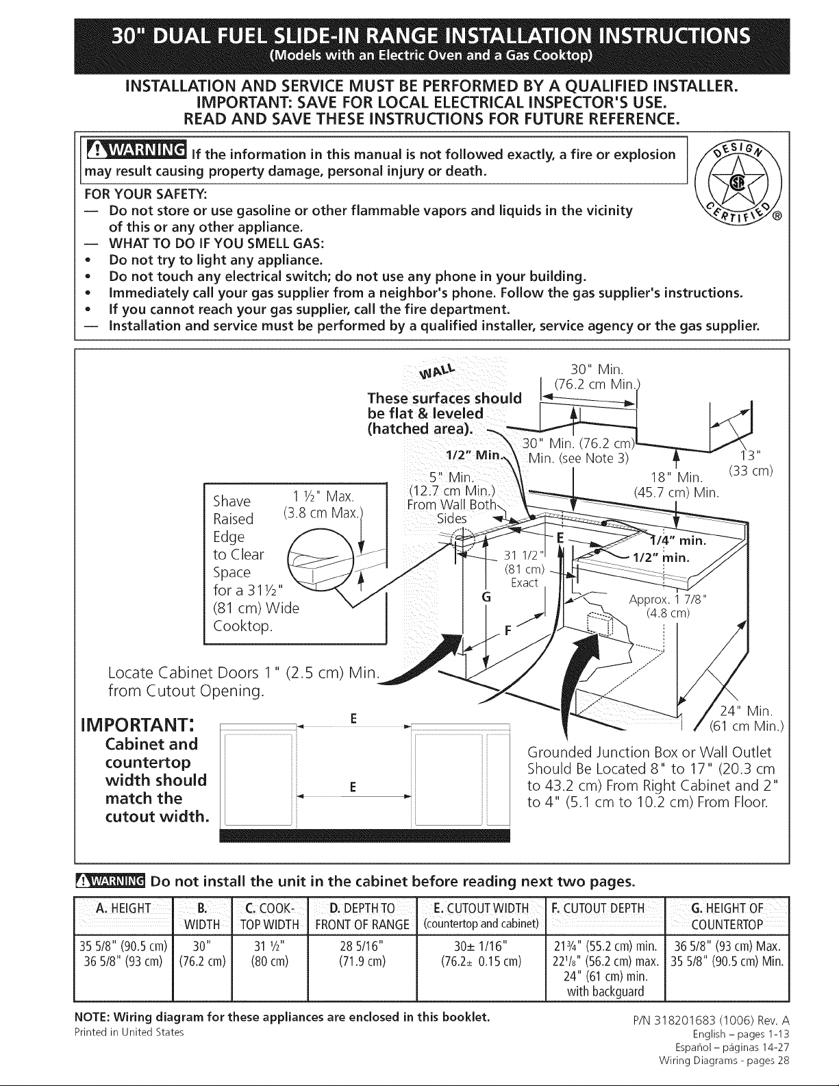
These surfaces should
be flat & leveled
(hatched area). _.%
3O"
Min. (76.2
1/2" Min.\
Shave
Raised
1 V2' Max
38 cm Max
5" Min.
_12.7 cm Min._
From Wall
Sides
18" Min.
(45.7 cm) Min.
Edge
to Clear
Space
fora 31Y2"
(81 cm) Wide
Cooktop.
Locate Cabinet Doors 1" (2.5 cm) Min.
from Cutout Opening.
IM PORTANT:
Cabinet and
countertop
width should
match the
E
Grounded Junction Box or Wall Outlet
Should Be Located 8" to 17" (20.3 cm
to 43.2 cm) From Right Cabinet and 2"
to 4" (5.1 cm to 10.2 cm) From Floor.
cutout width.
Do not install the unit in the cabinet before reading next two pages.
A, HEIGHT B, C. COOK_ D, DEPTHTO [ E,CUTOUTWIDTH F.CUTOUTDEPTH , G.HEIGHTOF
WIDTH TOPWlDTH FRONTOFRANGE (countertopandcabinet) = COUNTERTOP
35 5/8" (90.5cm) 30" 31 I/2" 28 5/16" 30+ 1/16" 213/4"(55.2cm)rain. 365/8" (93cm)Max.
36 5/8" (93cm) (76.2cm) (80cm) (71.9cm) (76.2+0.15cm) 221/8'' (56.2cm)max. 35 5/8" (90.5cm)Min.
24" (61cm)min.
with backguard
NOTE:Wiring diagram for these appliances are enclosed in this booklet.
Printed in United States
P/N318201683 (1006) Rev.A
Espahol- p_iginas 14-27
Wiring Diagrams - pages 28
24" Min.
(61 cm Min.)
English - pages 1-13
Page 2
NOTES:
_I Do not pinch the power supply cord between the range and the wall.
Do not seal the range to the side cabinets.
24" (61 cm) minimum clearance between the cooktop and the bottom of the cabinet when
the bottom of wood or metal cabinet is protected by not less than 1/4" (0.64 cm) flame
retardant millboard covered with not less than No. 28 MSG sheet metal, 0.015" (0.4 mm)
stainless steel, 0.024" (0.6 mm) aluminum, or 0.020" (0.5 mm) copper.
30" (76.2 cm) minimum clearance when the cabinet is unprotected.
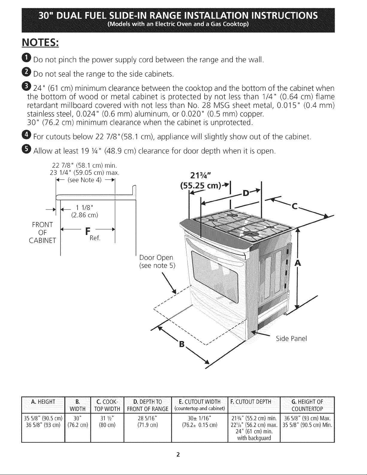
For cutouts below 22 7/8"(58.1 cm), appliance will slightly show out of the cabinet.
Allow at least 19 ¼" (48.9 cm) clearance for door depth when it is open.
22 7/8" (58.1 cm) min.
FRONT
OF
CABINET
23 1/4" (59.05 cm) max.
see Note 4)
1lZ8"
(2.86 cm)
m
Ref.
21¾"
(55.25 cm)-_ I
A HEIGHT' B;' C! COOKL
WIDTH TOPWIDTH
35 5/8" (90,5cm) 30" 31 I/2"
36 5/8" (93ca) (76.2ca) (80ca)
Door Open
(see note 5)
Side Panel
D. DEPTHTO' E,CUTOUTWlDTH F,CUTOUTDEPTH G' HEIGHTOF
FRONTOFRANGE (c0untert0pandcabnet) COUNTERTOP
28 5/16" 30_+1/16" 213/4"(55.2cm)rain. 36518"(93cm)Max.
(71.9cm) (76.2_+0.15cm) 221/8'' (56.2cm)max. 35 5/8" (90.5cm)Min.
24" (61cm)min.
with backguard
A
Page 3
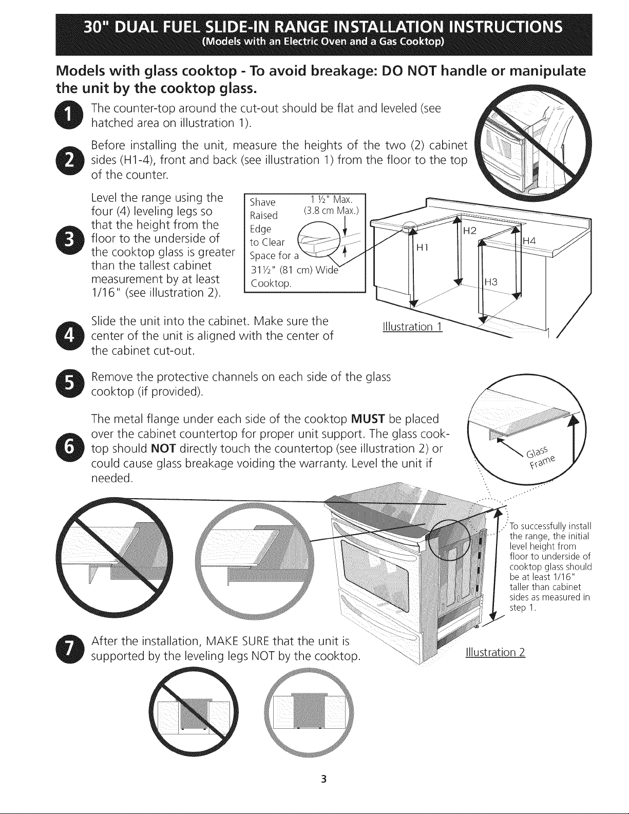
Models with glass cooktop - To avoid breakage: DO NOT handle or manipulate
the unit by the cooktop glass°
The counter-top around the cut-out should be flat and leveled (see
hatched area on illustration 1).
Before installing the unit, measure the heights of the two (2) cabinet
sides (H1-4), front and back (see illustration 1) from the floor to the top
of the counter•
Level the range using the
four (4) leveling legs so
that the height from the
floor to the underside of
the cooktop glass is greater
than the tallest cabinet
measurement by at least
Shave 1 1/2"Max.
Raised (3.8cm Max.)
Edge
to Clear
Spacefor
311/2" (81 cm)Wid_
Cooktop.
1/16" (see illustration 2).
Slide the unit into the cabinet. Make sure the
Illustration 1
center of the unit is aligned with the center of
the cabinet cut-out.
Remove the protective channels on each side of the glass
cooktop (if provided).
The metal flange under each side of the cooktop MUST be placed
over the cabinet countertop for proper unit support• The glass cook-
top should NOT directly touch the countertop (see illustration 2) or
could cause glass breakage voiding the warranty• Level the unit if
needed•
After the installation, MAKE SURE that the unit _s
supported by the leveling legs NOT by the cooktop.
3
To successfully install
the range, the initial
level height from
floor to underside of
cooktop glass should
be at least 1/16"
taller than cabinet
sides as measured in
step 1.
Illustration 2
Page 4
important Notes to the Installer
1. Read all instructions contained in these installation
instructions before installing range.
2. Removeallpacking material from the oven compartments
before connecting the gas and electrical supply to the
range.
3. Observe all governing codes and ordinances.
4. Be sure to leave these instructions with the consumer.
5. Note: For operation at 2000 ft. elevations above see
level, appliance rating shall be reduced by 4 percent for
each additional 1000 ft.
important Note to the Consumer
Keep these instructions with your Use & Care Guide for
future reference.
IMPORTANT SAFETY
INSTRUCTION
Installation of this range must conform with local codes
or, in the absence of local codes, with the National Fuel
Gas Code ANSI Z223. l--latest edition.
This range has been design certified by CSA international.
As with any appliance using gas and generating heat,
there are certain safety precautions you should follow. You
will find them in the Use and Care Guide, read it carefully.
• Be sure your range is installed and grounded
properly by a qualified installer or service
technician.
This range must be electrically grounded in
accordance with local codes or, in their absence,
with the National Electrical Code ANSI/NFPA No.
70--latest edition. See Grounding Instructions.
The installation of appliances designed for manufactured
(mobile) home installation mustconform with Manufactured
Home Construction and Safety Standard, title 24CFR,part
3280 [Formerly the Federal Standard for Mobile Home
Construction and Safety, title 24, HUD (part 280)] or
when such standard is not applicable, the Standard for
Manufactured Home Installation 1982 (Manufactured
Home Sites, Communities and Setups), ANSI Z225.1/NFPA
501A-latest edition, or with local codes.
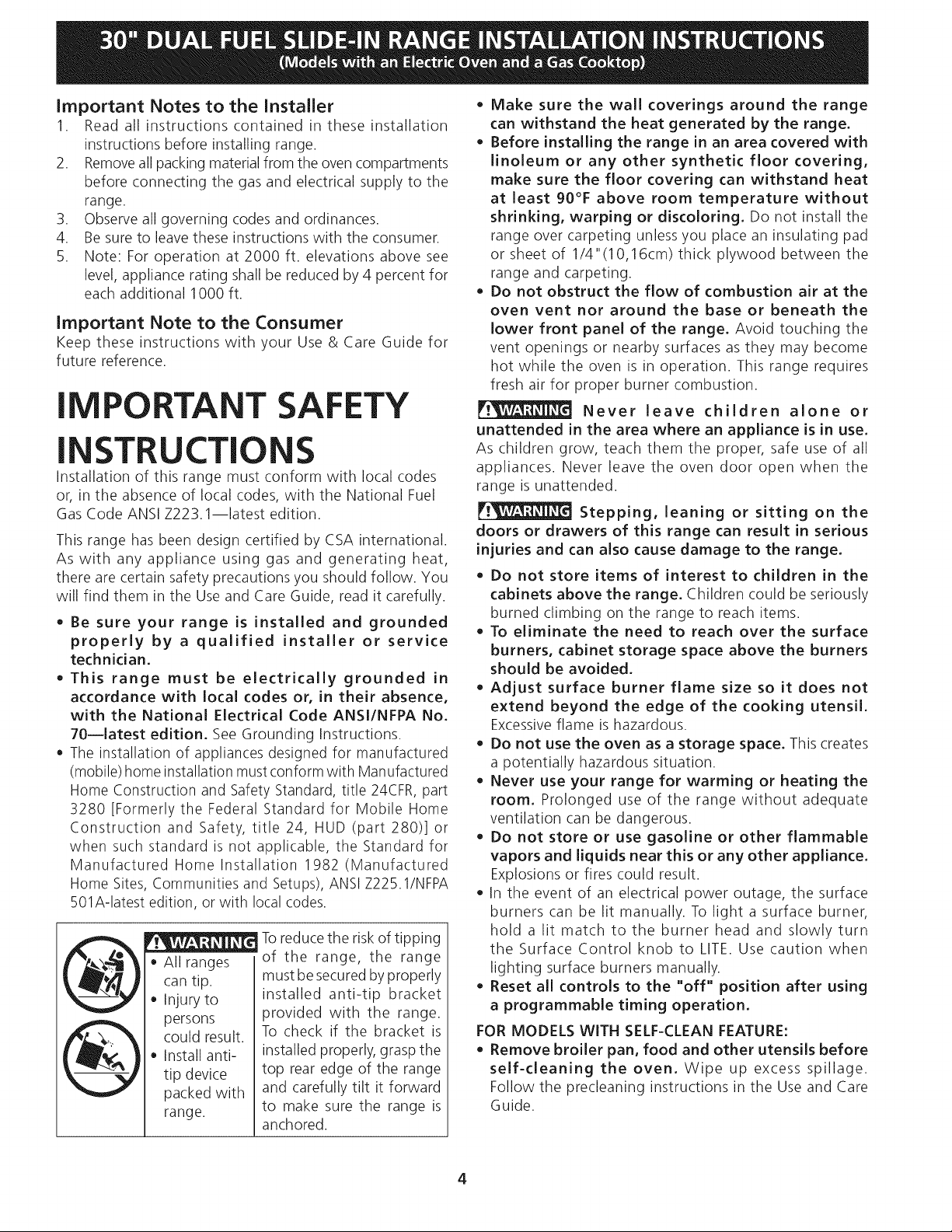
Toreduce the risk of tipping
All ranges of the range, the range
can tip.
Injury to
persons
could result.
Install anti-
tip device
packed with
range.
must besecuredby properly
installed anti-tip bracket
provided with the range.
To check if the bracket is
installed properly, grasp the
top rear edge of the range
and carefully tilt it forward
to make sure the range is
anchored.
Make sure the wall coverings around the range
can withstand the heat generated by the range.
Before installing the range in an area covered with
linoleum or any other synthetic floor covering,
make sure the floor covering can withstand heat
at least 90°F above room temperature without
shrinking, warping or discoloring. Do not install the
range over carpeting unless you place an insulating pad
or sheet of 1/4"(10,16cm) thick plywood between the
range and carpeting.
Do not obstruct the flow of combustion air at the
oven vent nor around the base or beneath the
lower front panel of the range. Avoid touching the
vent openings or nearby surfaces as they may become
hot while the oven is in operation. This range requires
fresh air for proper burner combustion.
Never leave children alone or
unattended in the area where an appliance is in use.
As children grow, teach them the proper, safe use of all
appliances. Never leave the oven door open when the
range is unattended.
Stepping, leaning or sitting on the
doors or drawers of this range can result in serious
injuries and can also cause damage to the range.
Do not store items of interest to children in the
cabinets above the range. Children could be seriously
burned climbing on the range to reach items.
To eliminate the need to reach over the surface
burners, cabinet storage space above the burners
should be avoided.
• Adjust surface burner flame size so it does not
extend beyond the edge of the cooking utensil.
Excessiveflame is hazardous.
Do not use the oven as a storage space. This creates
a potentially hazardous situation.
• Never use your range for warming or heating the
room. Prolonged use of the range without adequate
ventilation can be dangerous.
Do not store or use gasoline or other flammable
vapors and liquids near this or any other appliance.
Explosions or fires could result.
In the event of an electrical power outage, the surface
burners can be lit manually. To light a surface burner,
hold a lit match to the burner head and slowly turn
the Surface Control knob to LITE. Use caution when
lighting surface burners manually.
Reset all controls to the "off" position after using
a programmable timing operation.
FOR MODELS WITH SELF-CLEAN FEATURE:
• Remove broiler pan, food and other utensils before
self-cleaning the oven. Wipe up excess spillage.
Follow the precleaning instructions in the Use and Care
Guide.
4
Page 5
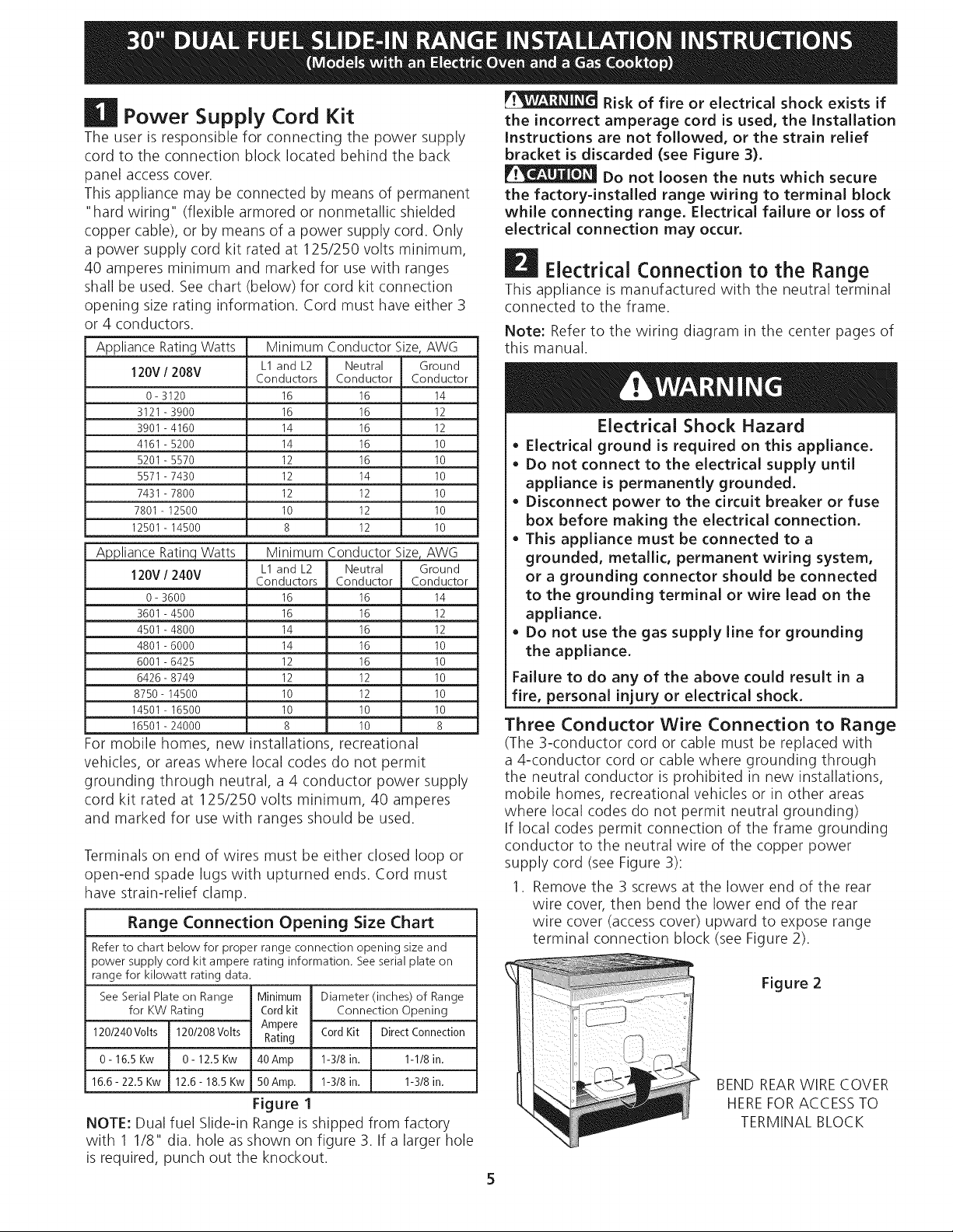
| Power Supply Cord Kit
The user is responsible for connecting the power supply
cord to the connection block located behind the back
panel access cover.
This appliance may be connected by means of permanent
"hard wiring" (flexible armored or nonmetallic shielded
copper cable), or by means of a power supply cord. Only
a power supply cord kit rated at 125/250 volts minimum,
40 amperes minimum and marked for use with ranges
shall be used. See chart (below) for cord kit connection
opening size rating information. Cord must have either 3
or 4 conductors.
Appliance Rating Watts Minimum Conductor Size, AWG
120V / 208V Conductors Conductor Conductor
0-3120 16 16 14
3121-3900 16 16 12
3901-4160 14 16 12
4161-5200 14 16 10
5201-5570 12 16 10
5571-7430 12 14 10
7431-7800 12 12 10
7801-12500 10 12 10
12501-14500 8 12 10
Appliance Rating Watts Minimum Conductor Size, AWG
120V / 240V Conductors Conductor Conductor
0-3600 16 16 14
3601-4500 16 16 12
4501-4800 14 16 12
4801-6000 14 16 10
6001-6425 12 16 10
6426-8749 12 12 10
8750-14500 10 12 10
14501-16500 10 10 10
16501-24000 8 10 8
For mobile homes, new installations, recreational
vehicles, or areas where local codes do not permit
grounding through neutral, a 4 conductor power supply
cord kit rated at 125/250 volts minimum, 40 amperes
and marked for use with ranges should be used.
Terminals on end of wires must be either closed loop or
open-end spade lugs with upturned ends. Cord must
have strain-relief clamp.
Range Connection Opening Size Chart
Refer to chart below for proper range connection opening size and
power supply cord kit ampere rating information. See serial plate on
range for kilowatt rating data.
See Serial Plate on Range
for KW Rating
120/240Volts 120/208Volts
0- 16.5 Kw 0 - 12.5 Kw
16.6- 22.5 Kw 12.6- 18.5 Kw
NOTE: Dual fuel Slide-in Range isshipped from factory
with 1 1/8" dia. hole asshown on figure 3. If a larger hole
is required, punch out the knockout.
L1and L2 Neutral Ground
L1and L2 Neutral Ground
Minimum Diameter (inches) of Range
Cord kit Connection Opening
Ampere CordKit DirectConnection
Rating
40Amp 1-3/8 in. 1-1/8in.
50Amp. 1-3/8 in. 1-3/8in.
Figure 1
Risk of fire or electrical shock exists if
the incorrect amperage cord is used, the Installation
Instructions are not followed, or the strain relief
bracket is discarded (see Figure 3).
Do not loosen the nuts which secure
the factory=installed range wiring to terminal block
while connecting range. Electrical failure or loss of
electrical connection may occur.
m
r_4 Electrical Connection to the Range
This appliance is manufactured with the neutral terminal
connected to the frame.
Note: Refer to the wiring diagram in the center pages of
this manual.
Electrical Shock Hazard
• Electrical ground is required on this appliance.
• Do not connect to the electrical supply until
appliance is permanently grounded.
• Disconnect power to the circuit breaker or fuse
box before making the electrical connection.
• This appliance must be connected to a
grounded, metallic, permanent wiring system,
or a grounding connector should be connected
to the grounding terminal or wire lead on the
appliance.
• Do not use the gas supply line for grounding
the appliance.
Failure to do any of the above could result in a
fire, personal injury or electrical shock,
Three Conductor Wire Connection to Range
(The 3-conductor cord or cable must be replaced with
a 4-conductor cord or cable where grounding through
the neutral conductor is prohibited in new installations,
mobile homes, recreational vehicles or in other areas
where local codes do not permit neutral grounding)
If local codes permit connection of the frame grounding
conductor to the neutral wire of the copper power
supply cord (see Figure 3):
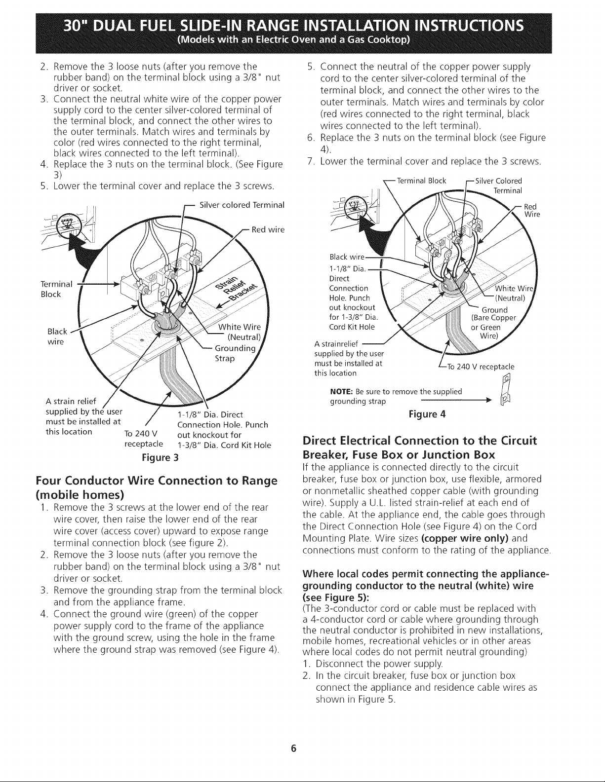
, Remove the 3 screws at the lower end of the rear
wire cover, then bend the lower end of the rear
wire cover (access cover) upward to expose range
terminal connection block (see Figure 2).
Figure 2
BEND REARWIRE COVER
HEREFOR ACCESSTO
TERMINAL BLOCK
Page 6
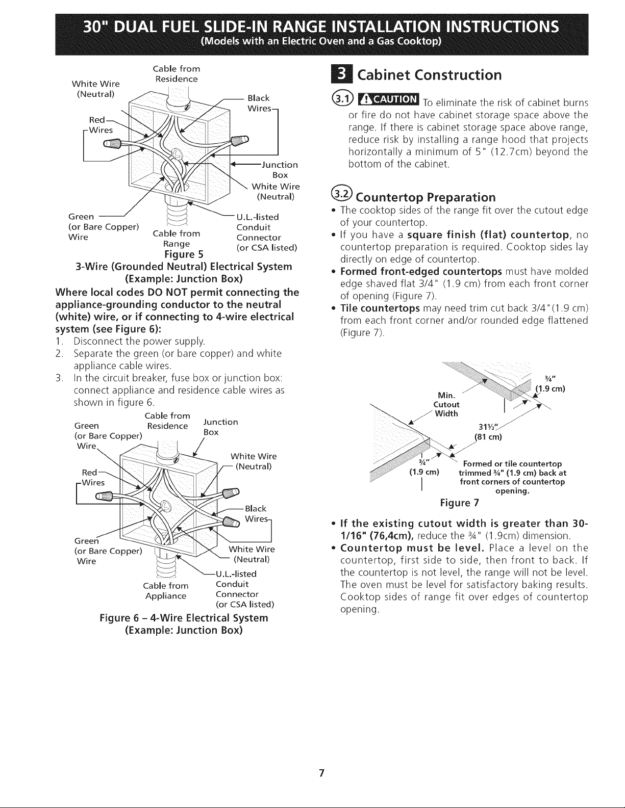
2. Removethe3 loosenuts(afteryouremovethe
rubberband)ontheterminalblockusinga3/8"nut
driverorsocket.
3. Connect the neutral white wire of the copper power
supply cord to the center silver-colored terminal of
the terminal block, and connect the other wires to
the outer terminals. Match wires and terminals by
color (red wires connected to the right terminal,
black wires connected to the left terminal).
4. Replace the 3 nuts on the terminal block. (See Figure
3)
5. Lower the terminal cover and replace the 3 screws.
Silver colored Terminal
wire
Terminal
Block
Black
wire
5. Connect the neutral of the copper power supply
cord to the center silver-colored terminal of the
terminal block, and connect the other wires to the
outer terminals. Match wires and terminals by color
(red wires connected to the right terminal, black
wires connected to the left terminal).
6. Replace the 3 nuts on the terminal block (see Figure
4).
7. Lower the terminal cover and replace the 3 screws.
Block Colored
Terminal
Red
Wire
Black
1-1/8"
Direct
Connection
Hole. Punch
out knockout
for 1-3/8" Dia.
Cord Kit Hole
A strainrelief
supplied by the user
must be installed at To240 V receptacle
this location
A strain relief
supplied by the user 1-1/8" Dia. Direct
must be installed at Connection Hole. Punch
this location To 240 V out knockout for
receptacle 1-3/8" Dia. Cord Kit Hole
Figure 3
Four Conductor Wire Connection to Range
(mobile homes)
1. Remove the 3 screws at the lower end of the rear
wire cover, then raise the lower end of the rear
wire cover (access cover) upward to expose range
terminal connection block (see figure 2).
2. Remove the 3 loose nuts (after you remove the
rubber band) on the terminal block using a 3/8" nut
driver or socket.
3. Remove the grounding strap from the terminal block
and from the appliance frame.
4. Connect the ground wire (green) of the copper
power supply cord to the frame of the appliance
with the ground screw, using the hole in the frame
where the ground strap was removed (see Figure 4).
NOTE: Be sure to remove the supplied !_l
grounding strap }>
Figure 4
Direct Electrical Connection to the Circuit
Breaker, Fuse Box or Junction Box
If the appliance is connected directly to the circuit
breaker, fuse box or junction box, use flexible, armored
or nonmetallic sheathed copper cable (with grounding
wire). Supply a U.L. listed strain-relief at each end of
the cable. At the appliance end, the cable goes through
the Direct Connection Hole (see Figure 4) on the Cord
Mounting Plate. Wire sizes (copper wire only) and
connections must conform to the rating of the appliance.
Where local codes permit connecting the appliance-
grounding conductor to the neutral (white) wire
(see Figure 5):
(The 3-conductor cord or cable must be replaced with
a 4-conductor cord or cable where grounding through
the neutral conductor is prohibited in new installations,
mobile homes, recreational vehicles or in other areas
where local codes do not permit neutral grounding)
1. Disconnect the power supply.
2. In the circuit breaker, fuse box or junction box
connect the appliance and residence cable wires as
shown in Figure 5.
Page 7
Cable from
White Wire
(Neutral)
Green U.L.-listed
(or Bare Copper) Conduit
Wire Cable from Connector
Residence
-- Black
Wires-
Box
White Wire
(Neutral)
Range (or CSA listed)
Figure 5
3-Wire (Grounded Neutral) Electrical System
(Example: Junction Box)
Where local codes DO NOT permit connecting the
appliance-grounding conductor to the neutral
(white) wire, or if connecting to 4-wire electrical
system (see Figure 6):
1. Disconnect the power supply.
2. Separate the green (or bare copper) and white
appliance cable wires.
3. In the circuit breaker, fuse box or junction box:
connect appliance and residence cable wires as
shown in figure 6.
Cable from
Green Residence
(or Bare Copper)
Wire
Wires
Green
(or Bare Copper)
Wire
Cable from Conduit
Appliance Connector
Junction
Box
White Wire
(Neutral)
White Wire
_._ (Neutral)
U.L.-listed
(or CSA listed)
Figure 6 - 4-Wire Electrical System
(Example: Junction Box)
Cabinet Construction
@ _Jl__ To eliminate the risk of cabinet burns
or fire do not have cabinet storage space above the
range. If there is cabinet storage space above range,
reduce risk by installing a range hood that projects
horizontally a minimum of 5" (12.7cm) beyond the
bottom of the cabinet.
@ Countertop Preparation
• The cooktop sides of the range fit over the cutout edge
of your countertop.
• If you have a square finish (flat) countertop, no
countertop preparation is required. Cooktop sides lay
directly on edge of countertop.
• Formed front-edged countertops must have molded
edge shaved flat 3/4" (1.9 cm) from each front corner
of opening (Figure 7).
• Tile countertops may need trim cut back 3/4"(1.9 cm)
from each front corner and/or rounded edge flattened
(Figure 7).
....._.. 311/2'Y
_-'-_ (81cm)
ed or tile countertop
ed ¼" (1.9 cm) back at
I front corners of countertop
' opening.
Figure 7
o
If the existing cutout width is greater than 30-
1/16" (76,4cm), reduce the 3A" (1.9cm) dimension.
o
Countertop must be level. Place a level on the
countertop, first side to side, then front to back. If
the countertop is not level, the range will not be level.
The oven must be level for satisfactory baking results.
Cooktop sides of range fit over edges of countertop
opening.
7
Page 8
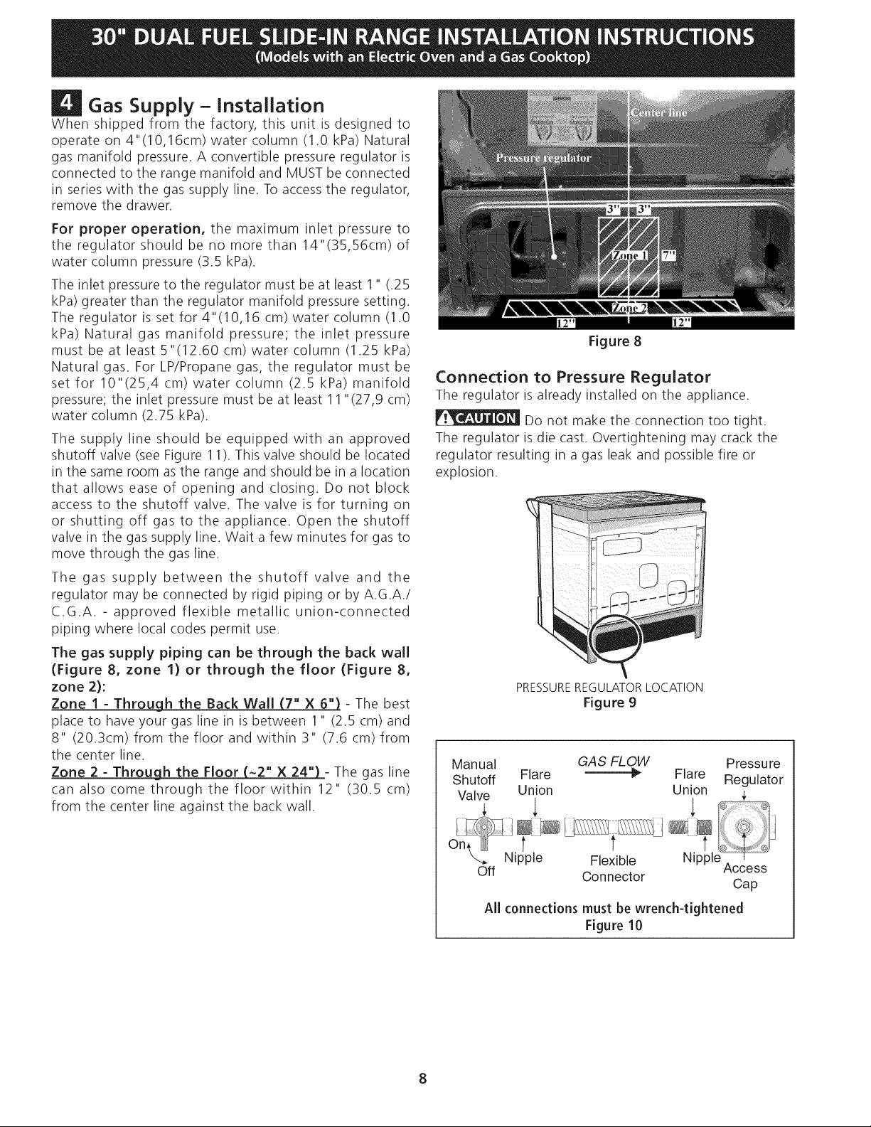
Gas Supply - Installation
When shipped from the factory, this unit is designed to
operate on 4"(10,16cm) water column (1.0 kPa) Natural
gas manifold pressure. A convertible pressure regulator is
connected to the range manifold and MUST be connected
in series with the gas supply line. To access the regulator,
remove the drawer.
For proper operation, the maximum inlet pressure to
the regulator should be no more than 14"(35,56cm) of
water column pressure (3.5 kPa).
The inlet pressure to the regulator must be at least 1" (.25
kPa) greater than the regulator manifold pressure setting.
The regulator is set for 4"(10,16 cm) water column (1.0
kPa) Natural gas manifold pressure; the inlet pressure
must be at least 5"(12.60 cm) water column (1.25 kPa)
Natural gas. For LP/Propane gas, the regulator must be
set for 10"(25,4 cm) water column (2.5 kPa) manifold
pressure; the inlet pressure must be at least 11 "(27,9 cm)
water column (2.75 kPa).
The supply line should be equipped with an approved
shutoff valve (see Figure 11). This valve should be located
in the same room as the range and should be in a location
that allows ease of opening and closing. Do not block
access to the shutoff valve. The valve is for turning on
or shutting off gas to the appliance. Open the shutoff
valve in the gas supply line. Wait a few minutes for gas to
move through the gas line.
The gas supply between the shutoff valve and the
regulator may be connected by rigid piping or by A.G.A./
C.G.A. - approved flexible metallic union-connected
piping where local codes permit use.
The gas supply piping can be through the back wall
(Figure 8, zone 1) or through the floor (Figure 8,
zone 2):
Zone I - Through the Back Wall (7" X 6") - The best
place to have your gas line in is between 1" (2.5 cm) and
8" (20.3cm) from the floor and within 3" (7.6 cm) from
the center line.
Zone 2 - Through the Floor (~2" X 24"_- The gas line
can also come through the floor within 12" (30.5 cm)
from the center line against the back wall.
Figure 8
Connection to Pressure Regulator
The regulator is already installed on the appliance.
Do not make the connection too tight.
The regulator is die cast. Overtightening may crack the
regulator resulting in a gas leak and possible fire or
explosion.
PRESSUREREGULATORLOCATION
Figure 9
Manual GAS FLOW Pressure
Shutoff Flare _ Flare Regulator
Valve Union Union
Off Connector
All connections must be wrench-tightened
Figure 10
Access
Cap
Page 9
Assembletheflexibleconnectorfromthegassupplypipe
tothepressureregulatorinthefollowingorder:
1. manualshutoffvalve(notsupplied)
2. 1/2"nipple(notsupplied)
3. 1/2"flareunionadapter(notsupplied)
4. flexibleconnector(notsupplied)
5. 1/2"flareunionadapter(notsupplied)
6. 1/2"nipple(notsupplied)
7. pressureregulator(supplied)
Thegassupplylinetotheshutoffvalveshouldbe
1/2"(1,27cm)or3/4"(1.9cm)solidpipe.
Theusermustknowthelocationofthemainshutoff
valveandhaveeasyaccesstoit.
Whenusingflexiblegasconduitontherange,allow
sufficientslackto pulltherangeoutsidethecutoutfor
cleaningorservicing.
NOTE:Donotallowtheflexibleconduitto getpinched
betweenthewallandtherange.Tovisuallycheck,
removetherangedrawer.
Usepipe-jointcompoundmadeforusewithNaturaland
LP/Propanegastosealallgasconnections.Ifflexible
connectorsareused,becertainconnectorsarenot
kinked.
Donotuseaflameto checkforleaks
fromgasconnections.Checkingforleakswithaflame
mayresultinafireorexplosion.
Allopeningsinthewallorfloorwheretherangeisto be
installedmustbesealed.
Tightenallconnectionsif necessaryto preventgas
leakageinthecooktoporsupplyline.
Disconnectthis rangeandits individualshutoff
valvefromthegassupplypipingsystemduringany
pressuretestingofthesystemattestpressuresgreater
than1/2psig(3.5kPaor 14"(35,56cm)watercolumn).
Isolatetherangefrom thegassupplypipingsystem
byclosingitsindividualmanualshutoffvalveduring
anypressuretestingofthegassupplypipingsystemat
testpressuresequaltoor lessthan1/2psig(3.5kPaor
14"(35,56cm)watercolumn).
LP/Propane Gas Conversion
This appliance can be used with Natural gas or LP/
Propane gas. It is shipped from the factory for use with
natural gas.
If you wish to convert your range for use with LP/
Propane gas, use the supplied fixed orifices located in a
bag containing the literature marked "FOR LP/PROPANE
GAS CONVERSION." Follow the instructions packaged
with the orifices.
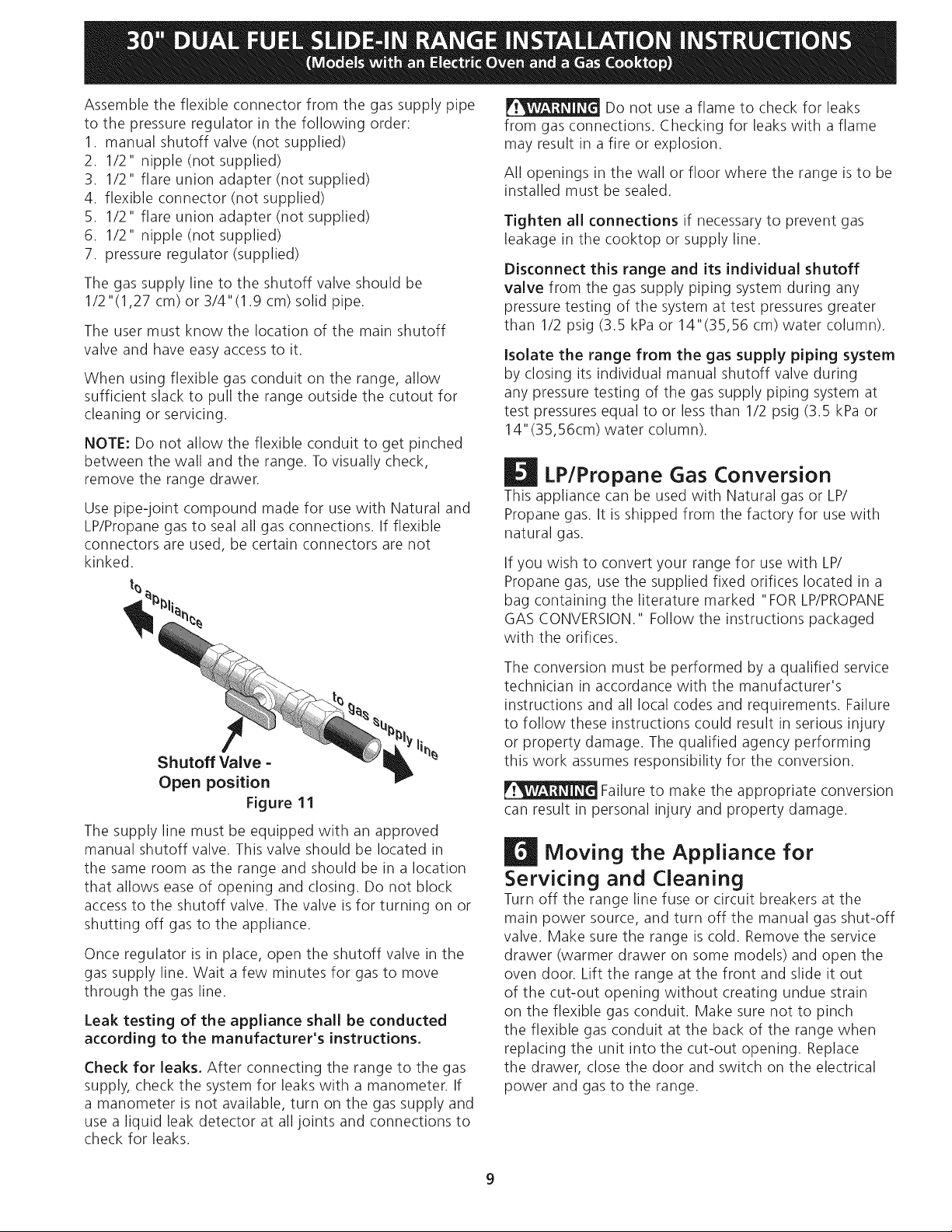
Shutoff Valve -
Open position
Figure 11
The supply line must be equipped with an approved
manual shutoff valve. This valve should be located in
the same room as the range and should be in a location
that allows ease of opening and closing. Do not block
access to the shutoff valve. The valve isfor turning on or
shutting off gas to the appliance.
Once regulator is in place, open the shutoff valve in the
gas supply line. Wait a few minutes for gas to move
through the gas line.
Leak testing of the appliance shall be conducted
according to the manufacturer's instructions,
Check for leaks. After connecting the range to the gas
supply, check the system for leaks with a manometer. If
a manometer is not available, turn on the gas supply and
use a liquid leak detector at all joints and connections to
check for leaks.
The conversion must be performed by a qualified service
technician in accordance with the manufacturer's
instructions and all local codes and requirements. Failure
to follow these instructions could result in serious injury
or property damage. The qualified agency performing
this work assumes responsibility for the conversion.
Failure to make the appropriate conversion
can result in personal injury and property damage.
| Moving the Appliance for
Servicing and Cleaning
Turn off the range line fuse or circuit breakers at the
main power source, and turn off the manual gas shut-off
valve. Make sure the range is cold. Remove the service
drawer (warmer drawer on some models) and open the
oven door. Lift the range at the front and slide it out
of the cut-out opening without creating undue strain
on the flexible gas conduit. Make sure not to pinch
the flexible gas conduit at the back of the range when
replacing the unit into the cut-out opening. Replace
the drawer, dose the door and switch on the electrical
power and gas to the range.
9
Page 10

| Range Installation
Important Note: Door removal is not a requirement for
installation of the range, but is an added convenience.
Refer to the Use and Care Guide for oven door removal
instructions.
O Position range in front of the cabinet opening.
O Make sure that the cooktop which overhangs the
countertop clears the countertop. If necessary, raise
the unit by lowering the leveling legs.
Standard Installation
O The range cooktop overlaps the countertop at the
sides and the range rests on the floor. The cooktop
is 31 1/2" (81 cm) wide.
O
Install base cabinets 30" (76.2 cm) apart. Make sure
they are plumb and level before attaching cooktop.
Shave raised countertop edge to clear 31/2'` (81 cm)
wide range top rim.
O
Install cabinet doors 31 " (78.7 cm) min. apart so as
not to interfere with range door opening.
O
Cutout countertop exactly as shown on page 1.
O
Make sure the four leveling legs (front and rear) are
setup higher than the height of the cabinet (shown
on page 3).
O _ Install the anti-tip bracket at
this point before placing the range at its final
position. Follow the installation instructions on
page 13 or on the anti-tip bracket template supplied
with the range.
O Level the range (see section 8). The floor where
the range is to be installed must be level. Follow the
instructions under "Leveling the Range".
O Slide the range into the cutout opening.
If Accessories Needed
Installation With Backguard
The cutout depth of (21 3/4" (55.2 cm)Min., 22 1/8"
(56.2cm) Max.) needs to be increased to 24" (61 cm)
when installing a backguard.
Installation With End Panel
A End Panel kit can be ordered through a Service
Center.
Installation With Side Panels
A Side Panels kit can be ordered through a Service
Center.
Install cabinet doors 31 " (78.7 cm) min. apart so as
not to interfere with range door opening.
O To provide an optimum installation, the top surface
of the countertop must be level and flat (lie on the
same plane) around the 3 sides that are adjacent
to range cooktop. Proper adjustments to make
the top flat should be made or gaps between the
countertop and the range cooktop may occur.
O[I__ To reduce the risk of damaging your
appliance, do not handle or manipulate it by the
ceramic glass. Manipulate with care.
10
Page 11

Leveling the Range -
Level the range after installation in the cutout
opening.
1. Open the range drawer. The leveling screws control
the height of the rear leg.
2. Adjust the appliance legs as follows until the
underside of the cooktop surface is sitting level on
the countertop (Figure 12).
n
Decorative Rear Trim Installation
(if required)
1. Disconnect the power from the range.
2. Make sure the range is leveled.
3. Pull range toward you.
4. Measure the distance between the floor and the
surface underneath the cooktop frame.
5. Mark that distance on the wall where the decorative
trim will be installed.
6. Draw a line.
7. Place the top of the decorative trim under that line.
8. Using the screws provided fix the decorative trim into
the wall.
9. Slide the range back into position as far as it will go
and reconnect the power source.
Decorative Trim
DeviceHiFg,ti
RAISE i
Font
Leveling
Leg
LOWER
RAISE
Figure 12
A. To adjust the front leveling legs, use a wrench and
turn counterclockwise to lower or clockwise to raise.
B. To adjust the rear leveling screws, use a ratchet or
a nut driver and turn counterclockwise to lower or
clockwise to raise.
3. Check if the range is level by installing an oven rack
in the center of the oven and placing a level on the
rack (Figure 13)
4. Take 2 readings with the level placed diagonally in
one direction and then the other. Level the range, if
necessary, by adjusting the leveling legs.
5. If the range is not level, contact a carpenter to
correct sagging or sloping floor.
-:Screw (3)
Distance between
the floor and
the surface
underneath the
cooktop frame.
Figure 14
Check Operation
Refer to the Use and Care Guide packaged with the
range for operating instructions and for care and
cleaning of your range.
Do not touch the elements or burners. They may be hot
enough to cause burns.
Remove all packaging from the oven before testing.
Figure 13
1.Install Burner Bases and Burner Caps
This range is equipped with sealed burners as
shown (see Figure 15 on next page).
1. Unpack burner bases and burner caps.
2. Place burner bases over each gas opening.
3. Make sure the burner is properly aligned and leveled.
Place burner caps over appropriate burner bases.
11
Page 12

5. Operationof OvenElements
Theovenisequippedwithanelectronicovencontrol.Each
ofthefunctionshasbeenfactorycheckedbeforeshipping.
However,itissuggestedthatyouverifytheoperation
oftheelectronicovencontrolsoncemore.Refertothe
ElectronicOvenControlGuideforoperation.Followthe
instructionsfortheClock,Timer,Bake,Broil,Convection
(somemodels)andCleanfunctions.
Figure15
NOTE:Thereareno
burneradjustmentsnecessaryonthisrange.
2.Turnon ElectricalPowerandOpenMainShutoff
Gas Valve
3.Check the Igniters
Operation of electric igniters should be checked after
range and supply line connectors have been carefully
checked for leaks and range has been connected to
electric power. Tocheck for proper lighting:
1.Push in and turn a surface burner knob to the LITE
position. You will hear the igniter sparking.
2. The surface burner should light when gas is available
to the top burner. Each burner should light within
four (4) seconds in normal operation after air has been
purged from supply lines. Visually check that burner
has lit.
3.Once the burner lights, the control knob should be
rotated out of the LITEposition.
There are separate ignition devices for each burner. Try
each knob separately until all burner valves have been
checked.
4.Adjust the ""LOW"" Setting of Surface Burner
Valves (see Figure 16)
1.Push in and turn each control
to LITE until burner ignites.
2.Qukkly turn knob to
LOWEST POSITION.
3.If burner goes out, readjust
valve as follows: Figure 16
Reset control to OFF. Remove
the surface burner control knob, insert a thin-bladed
screw driver into the hollow valve stem and engage
the slotted screw inside. Flame size can be increased
or decreased with the turn of the screw. Adjust flame
until you can quickly turn knob from LITEto LOWEST
POSITIONwithout extinguishing the flame. Flame
should be as small as possible without going out.
Bake-Aftersettingtheovento350°F(177°C)for
baking,thelowerelementintheovenshouldbecome
red.
Broil-Whentheovenissetto BROIL,theupperelement
intheovenshouldbecomered.
Clean-When the oven is set for a self-cleaning cycle, the
upper element should become red during the preheat
portion of the cycle. After reaching the self-cleaning
temperature, the lower element will become red.
Convection (some models)-When the oven is set to
CONV. BAKE/ROAST at 350°F (177°C), the convection
element cycles on and off and the convection fan turns.
The convection fan will stop turning when the oven door
is opened during convection baking or roasting.
Warmer Drawer (some models)-Set the control knob
to HI and check to see the drawer is heating.
When All Hookups are Complete
Make sure all controls are left on the OFFposition.
Make sure the flow of combustion anf ventilation air to
the range is unobstructed.
Model and Serial Number Location
The serial plate is located on the oven front frame behind
the oven door (some models) or on the drawer side
frame (some models).
When ordering parts for or making inquiries about your
range, always be sure to include the model and serial
numbers and a lot number or letter from the serial plate
on your range.
Your serial plate also tells you the rating of the burners,
the type of fuel and the pressure the range was adjusted
for when it left the factory.
Before You Call for Service
Read the Before You Call Checklist and operating
instructions in your Use and Care Guide. It may save you
time and expense. The list includes common occurrences
that are not the result of defective workmanship or
materials in this appliance.
Refer to your Use & Care Guide for Sears service phone
numbers or call 1-800-4-MY-HOME®.
12
Page 13

Anti-Tip Brackets Installation
instructions
Toreduce the riskof tipping of the range,
the range must be secured to the floor by properly
installed anti-tip bracket and screws packed with the
range. Those parts are located in the oven. Failure to
install the anti-tip bracket will allow the range to tip over
if excessiveweight is placed on an open door or if achild
climbs upon it. Serious injury might result from spilled hot
liquids or from the range itself.
Follow the instructions below to install the anti-tip
brackets.
If range is ever moved to a different location, the anti-
tip brackets must also be moved and installed with the
range.
Tools Required:
Adjustable Wrench
Ratchet
Drill & 1/8"(0,32 cm) bit
5/16"(0,79 cm) Nutdriver
Level
Kitchen
Cabinet
Toe
Plate
iii
;i
j Door
i Cabinet
The anti-tip bracket attaches to the floor at the back of
the range to hold range rear center leg. When fastening
bracket to the floor, be sure that screws do not penetrate
electrical wiring or plumbing. The screws provided will
work in either wood or concrete.
1. Draw a center line (CL)on the floor where the range
should be installed. Also draw a line on the floor at
the range back position if there is no wall.
2. Unfold paper template and place it flat on the floor
positioned exactly on the intersection of the center
and back lines you just drew before. (Use the diagram
below to locate brackets if template is not available
(Figure 17)).
3. Mark on the floor the location of the 4 mounting
holes shown on the template. For easier installation,
3/16"(0,48cm) diameter pilot holes 1/2"(1,27cm)
deep can be drilled into the floor.
4. Remove template and place bracket on floor. Line up
holes in bracket with marks on floor and attach with
4 screws provided. Bracket must be secured to solid
floor (Figure 18). If attaching to concrete floor, first
drill 3/16"(0,48cm) dia. pilot holes using a masonry
drill bit.
5. Be sure the leveling legs and leveling device are at
the highest position they can be.
6. Slide range into place making sure rear center leg
is trapped by the anti-tip bracket (Figure 18). Lower
the range by adjusting the leveling legs and leveling
device until the underside of the cooktop is sitting
leveled on the countertop. Refer to "Leveling the
Range" section.
7. After installation, verify that the anti-tip bracket is
engaged by grasping the top rear edge of the range
and carefully attempt to tilt it forward to make sure
range is properly anchored.
Figure 17
SLIDE
BACK
13
Floor Mc
Screws
Figure 18
Page 14

LA INSTALACION Y EL SERVICIO DEBEN SER EFECTUADOS POR UN INSTALADOR CALIFICADO.
IMPORTANTE: GUARDE ESTAS INSTRUCCIONES PARA USO DEL INSPECTOR LOCAL DE
ELECTRICIDAD. LEA Y GUARDE ESTAS INSTRUCCIONES PARA REFERENCIA FUTURA.
W_J_ Si la informacion contenida en este manual no es seguida exactamente,
puede ocurrir un incendio o explosi6n causando daSos materiales, lesion personal o la muerte.
PARA SU SEGURIDAD:
-- No almacene ni utilice gasolina u otros vapores y liquidos inflamables en la proximidad
de _ste o de cualquier otro artefacto.
-- QUE DEBE HACER SI PERCIBEOLOR A GAS:
• No trate de encender ningun artefacto.
No toque ningun interruptor electrico, no use ning_n tel_fono en su edificio.
o
Llamea su proveedor de gas desde el tel_fono de un vecino. Siga las instruccionesdel proveedor de gas.
Si no Iogra comunicarse con su proveedor de gas, Ilame al departamento de bomberos.
La instalad6n y el servicio de mantenimiento deben set efectuados pot un instalador calificado, la agencia
de servicio o el proveedor de gas.
La superfide debe
estar plana y nivelada
Acepille el borde
subido a que
deje espacio
para un
borde
311/2''
(81 cm)
de anchura
de estufa
(area sombread_
1/2" Min,:
Min. 5'!
(!2.7 Cm) d e la Paredi
1Y2"M_ix. ambos lados: :
(3,8 cm M_ix.)
18" Min.
(45.7 cm) Min.
3"
(33 cm)
Localice las puertas del armario
1 "(2.5 cm) rain del hueco de la
abertura.
IMPORTANTE: El
24" Min.
(61 cm Min.)
ancho de la cubierta
y el armario debe
de set igual al ancho
del torte.
Lacaja de empalmes o el enchufe con puesta
a tierra deberia situarse de 8" a 17" (20.3 cm
a 43.2 cm) del armario derecho y de 2" a 4"
(5.1 cm a 10.2 cm) del suelo.
No instale la unidad en el gabinete si no ha lado esta 2 p_qginas.
AIALTURA' C.ANCHO D,)PROFUNDiDADA, F. I G,
ANCHO DELA LA FRENTEDE LA RE£ORTADO PROFUNDIDAD DE ALTURA DEL
I _COCINAR I I I
35 5/8" (90,5cm) 30" 31 1/2" 28 5/16" 30_+1/16" 213/4"(55.2cm)rain. 365/8" (93cm)Max.
36 5/8" (93cm) (76.2cm) (80cm) (71.9cm) (76.2_+0.15cm) 221/s'' (56.2cm)max. 35 5/8" (90.5cm)Min.
NOTA: Se adjunta el diagrama de cables de esta cocina al final de este libreta.
Imprimido en losEstadosUnidos
PLANCHA DE : ESTUFA ' (cubiertay armario) RECORTADO" MOSTRADOR
24" (61cm)Uin, con
un protector trasero.
P/N318201683 (1006) Rev.A
English - pages 1-13
Espaflol- p_iginas 14-27
Diagrama de la instalaci6n akimbrica - p_iginas 28
Page 15

NOTAS:
No pellizque el cordon electrico entre la estufa y la pared.
No selle la estufa a los armarios de lado.
Un espado minimo de 24" (61 cm) entre la superfide de la estufa y el fondo del
armario esto cuando el fondo del armario de madera o metal est,1 protegido por
no menos de 1/4" (0.64 cm) de madera resistente al fuego cubierta pot una I_mina
metcilica de MSG, n0mero 28, 0.015" (0.4 mm) de acero inoxidable, 0.024 (0.6
mm) aluminio, 0 0.020" (0.5 mm) de cobre.
Un espacio minimo de 30" (76.2 cm) cuando el armario no este protegido.
Para los recortados menos que 22 7/8", el electrodomestico apareceria ligeramente
en el exterior del armario.
Deje por los 19 ¼" (48.9 cm) de espacio libre para la profundidad de la puerta cuando
este abierta.
22 7/8" (58.1 cm) min.
23 1/4" (59.05 cm) max.
÷ (yea la nota 4) ÷ r
m
PARTE
DELANTERA
DEL
ARMARIO
A,_LTUR_ B:
ANCHO
355/8" (905 cm) 30"
36 5/8" (93 cm) (76.2 cm)
1 1/8"
_(2.86 cm)
F
Ref.
C:ANCHO
DELA
31V2"
(80cm)
I
Puerta abierta
(vea la nota 5)
D, PRoFUNDiDADA E. ANCH0DE F," G.
LA FRENTEDE LA RECORTADO PROFUNDiDAD DE ALTURA DEL
28 5/16" 30_+1/16" 213/4"(55.2 cm) rain. 36 5/8" (93 cm) Max.
(71.9 cm) (76.2+ 0.15 cm) 22118'' (56.2 cm) max. 35 5/8" (90.5 cm) Min.
24" (61 cm) Min con
un protector trasero.
A
Panel lateral
15
Page 16

Modelos con une cubierta de vidrio - Para evitar fractura de la unidad: NO
manipule la unidad sosteniendo la cubierta de vidrio.
La cubierta alrededor del espacio donde usted instalara su unidad
debe de estar plana y nivelada. (Vea el _qreasombreada en la
ilustracion n0mero 1)
Antes de instalar la unidad, mida la altura de los dos (2) lados de los
gabinetes (H1-4), frente y parte trasera (yea ilustracion 1) del piso a Io
alto de la cubierta.
Nivele la estufa usando
las 4 patas niveladoras de
manera que la altura del
piso a la superficie interior
de la cubierta de vidrio es
mayor que la altura del
gabinete mas alto de su
mobiliario de cocina por
Io menos por 1/1 6" (yea
ilustracion 2).
Deslice la unidad hacia el gabinete. Aseg0rese que la unidad este
centrada con el centro de la abertura del gabinete.
Lime el 1 1/2" Max.
horde (3.8 cm Max.)
levantado
para dejar
espacio
)ara una
unidad con un dimensi6n
31 Y2" (81 cm).
Ilustracion 1
1
Remueva la parte en pl_qstico extruido en cada lado de la cubierta de
vidrio. (Algunos modelos)
Esimprescindible que el reborde de metal que se encuentra debajo
de la cubierta este sobre la cubierta del gabinete. La cubierta de vidrio
no deber_qtocar directamente la cubierta del gabinete (yea ilustracion
2) de no ser asi la fractura del vidrio anular_i la garant[a. Nivele la
unidad si es necesario.
Despues de la instalacion, ASEGURESE que la
unidad este sostenida por las patas niveladoras y
NO por la cubierta.
Para instalar exito-
samente su estufa,
la medida inicial del
piso a la superficie
interior de la cubier-
ta de vidrio debe ser
mayor que la altura
del gablnete por Io
menos 1/16" como
se midi6 en el paso
nOmero 1.
Ilustracion 2
16
Page 17

Notas importantes para el instalador
1. Leatodas las instrucciones de instalaciOn antes de
realizar la instalaci6n de la plancha de cocinar.
2. Retire todos los articulos de embalaje antes de realizar
lasconexiones el_ctricas a la plancha de cocinar.
3. Observe todos los c6digos o reglamentos estatales
4. Aseg0rese que el consumidor tenga estas instrucciones.
5. Nota: Para la utilizaci6n a m_isde 2 000 pies de altura,
la potencia del aparato deber_i set reducida de 4 pot
ciento a cada 1 000 pies adicionales.
Notas irnportantes para el consurnidor
Guarde todas las instrucciones con su manual del usuario
para futuras referencias.
INSTRUCCIONES DE
SEGURIDAD IMPORTANTES
Instalacion de esta estufa debe cumplir con todos los
codigos locales, o en ausencia de codigos locales con el
Codigo Nacional de Gas Combustible ANSI Z223.1--01tima
edicion.
El diseho de esta estufa ha sido certificado pot la CSA
Internacional. En este como en cualquier otto artefacto
que use gas y genere calor, hay ciertas precauciones de
seguridad que usted debe seguir. Estas set,in encontradas
en el Manual del Usuario, lealo cuidadosamente.
• Asegurese de que la estufa sea instalada y
conectada a tierra en forrna apropiada pot un
instalador calificado o pot un tecnico.
• Esta estufa debe set electricarnente puesta a tierra
de acuerdo con los codigos locales, o en su ausencia,
con el Codigo Electrico Nacional ANSI/NFPA No. 70,
ultirna edid6n. Vea las instrucciones para la puesta a
tierra en la p_igina 4.
• La instalacion de aparatos disehados para instalacion
en casas prefabricadas (moviles) debe conformar con el
Manufactured Home Construction and Safety Standard,
t[tulo 24CFR, parte 3280 [Anteriormente el Federal
Standard for Mobil Home Construction and Safety, t[tulo
24, HUD (parte 280)] o cuando tal est_indar no se aplica,
el Standard for Manufactured Home Installation 1982
(Manufactured Home sites, Communities and Setups),
ANSI Z225.1/NFPA 501A-ediciOn m_is reciente, o con los
codigos locales.
• Todas las
estufas
pueden
b volcarse.
• Esto podr[a
resultar en
lesiones
personales.
Instale el
dispositivo
antivuelcos
que se ha
empacado
junto con
esta estufa.
Para reducir el riesgo de
que se vuelque la estufa,
hay que asegurarla
adecuadamente colo
candole los soportes
antivuelco que se
proporcionan. Para
comprobar si estos est_in
instalados y apretados en
su lugar como se debe, ase
el borde trasero superior de
la estufa y cuidado samente
incline la hacia adelante
para asegurar que la estufa
se ancle.
• Antes de instalar la estufa en un _rea cuyo piso
este recubierto con lin61eo u otto tipo de piso
sintetico, asegurese de que estos puedan resistir
una ternperatura de pot Io rnenos 90°F sobre la
ternperatura arnbiental sin provocar encogirniento,
deformaci6n o decoloraci6n. No instale la estufa sobre
una alfombra al menos que coloque una plancha de
material aislante de pot Io menos 1/4 pulgada, entre la
estufa y la alfombra.
Asegurese de que el material que recubre las
paredes alrededor de la estufa, pueda resistir el
calor generado pot la estufa.
No obstruya el flujo del aire de combusti6n en la
ventilaci6n del homo ni tampoco alrededor de la
base o debajo del panel inferior delantero de la
estufa. Evite tocar las aberturas o &teas cercanas de la
ventilacion, ya que pueden estar muy calientes durante el
funcionamiento del homo. La estufa requiere aire fresco
para la combustion apropiada de los quemadores.
_Nunca deje ni_os solos o desatendidos
en un _rea donde un artefacto est_ siendo usado. A
medida que los nihos crecen, enseheles el uso apropiado y
de seguridad para todos los artefactos. Nunca deje la puerta
del homo abierta cuando la estufa est,1 desatendida.
__ No se pare, apoye o siente en las
puertas o cajones de esta estufa pues puede resultar
en serias lesiones y puede tarnbien causar da_o a la
estufa,
• No alrnacene articulos que puedan interesar a los
ni_os en los gabinetes sobre la estufa. Los nihos
pueden quemarse seriamente tratando de trepar a la
estufa para alcanzar estos art[culos.
• Los gabinetes de alrnacenarniento sobre la estufa
deben set evitados, para elirninar la necesidad de
tenet que pasar sobre los quernadores superiores de
la estufa para Ilegar a ellos.
• Ajuste el tarna_o de la llama de los quernadores
superiores de tal rnanera que esta no sobrepase el
borde de los utensilios de cocinar. La llama excesiva es
peligrosa.
No use el homo corno espacio de almacenaje. Esto
create1una situacion potencialmente peligrosa.
• Nunca use la estufa para calentar el cuarto. El uso
prolongado de la estufa sin la adecuada ventilacion puede
resultar peligroso.
• No almacene ni utilice gasolina u otros vapores y
liquidos inflarnables en la proxirnidad de este o de
cualquier otto artefacto electrico. Puede provocar
incendio o explosion.
En caso de una interrupcion del servicio electrico, es
posible de encender los quemadores de superficie a
mano. Para encender un quemador de superficie, acerque
un fosforo encendido del cabezal del quemador, y gire
delicadamente el boton de control de superficie a LITE
(encendido). Tenet cuidado al encender los quemadores a
mano.
• Ajuste todos los controles a la posici6n "OFF"
(apagada) despues de haber hecho una operaci6n
con tiernpo prograrnado.
PARA MODELOS AUTOLIMPIANTES:
• Saque la asadera, alimentos o cualquier otto
utensilio antes de usar el cido de autolirnpieza del
homo. Limpie todo exceso de derrame de alimentos.
Siga las instrucciones de prelimpiado en el Manual del
Usuario.
17
Page 18

N
Juego de Cordon Electrico
El consumidor tiene la responsabilidad de conectar el
cordOn el_ctrico al bloque de conexi0n ubicado detr_is de
la cubierta de acceso del panel trasero.
El electrodom_stico se puede conectar a trav_s de un
cableado permanente "cableado duro"; cable de cobre
blindado armado o cable no-met_qlico flexible (cuando el
c0digo local Io permite) o por medio de un kit de cable de
alimentaci0n. Vea la gr_ifica (en la p_qgina siguiente) para
encontrar el tamaho minimo del cable a utilizarse (el listado
general de la UL, c0digo local puede diferenciar).
Grado de vatiosdel electrodomestico
120V /208V
0-3120
3121-3900
3901-4160
4161-5200
5201-5570
5571-7430
7431-7800
7801-12500
12501-14500
GradodevatiosdeJelectrodomOstico
120V /240V
0-3600
3601-4500
4501-4800
4801-6000
6001-6425
6426-8749
8750-14500
14501-16500
16501-24000
Para las casas sobre ruedas, las nuevas instalaciones, en los
veh[culos de recreacion o en las _ireasdonde los codigos locales
no permiten la conexion del conductor a tierra al neutro, un
ensamblaje de suministro electrico de 4 conductores para
estufas, clasificado a 125/250 voltios m[nimo, 40 amperios
m[nimo, debe de set utilizado.
Los bornes a la extremidad de los alambres deben set a curvas
cerradas o con extremidades de leng0etas en forma de U
abiertas y curvadas. El cordon debe de tenet una abrazadera
releva de anclaje
Tabla de tama_o de abertura de conexion de cocina
Referirse a la tabla de arriba para el tamaho de abertura de conexi6n
de cocina adecuada, y la informaci6n sobre el r_gimen de amperios del
ensamblaje de cordon de suministro el_ctrico.
Vea la placa de serie para
informaci6n sobre el
r_qimen de kilovatio.
1201240 Volts 120/208 Volts
0 - 16.5 Kw 0 - 12.5 Kw
16.6- 22.5 Kw 12.6- 18.5 Kw
Nota: La cocina corrediza fuel dual viene de fabrica con un
agujero d di_imetro 1 1/8" come muestra en la figura 3. Si un
agujero mas largo est,1 necesario retire la arandela recortada.
Tamaho minimo del conductor AWG
Conductores
L1 yL2
16
16
14
14
12
12
12
10
8
Tamaho minlmo
Conductores
L1 yL2
16
16
14
14
12
12
10
10
8
Minimo
r_gimen de
amperios de
ensamblaje
del cordon
40Amp
Conductor Conductor
Neutral de Tierra
16 14
16 12
16 12
16 10
16 10
14 10
12 10
12 10
12 10
del conductor AWG
Conductor Conductor
Neutral de Tierra
16 14
16 12
16 12
16 10
16 10
12 10
12 10
10 10
10 8
Dkimetro (pulgadas) de
abierta de conexiOn de
cocina.
Ensamblaje Connect.
del cordon directa
1-3/8 in. 1-1/8 in.
1-3/8in. 1-3/8 !n_
Figura 1
Puede ocurrir riesgo de incendio o
choque electrico si se usa un juego de cord6n de estufa de
tarnaEo incorrecto, si las instrucdones de instalaci6n no son
seguidas o si no se usa el andaje del cable (vea Figura 3),
No desate las tuercas que sujetan
el alarnbraje de codna que ha sido instalado en la
factoria al bloque terminal, cuando se hace la conexi6n
de la cocina. Se puede ocurrir el rnal funcionarniento o
una interrupci6n del surninistro electrico,
Conexion Electrico de la Estufa
Este aparato se fabrica con el terminal neutro conectado al marco.
Refiere al diagrama de alambraje en las paginas de centro de
este manual.
Riesgo de Choque Electrico
• Una puesta a tierra est_ requerido en este aparato,
• No Io conecte a la corriente electrica hasta que el
aparato haya sido puesto a tierra permanentemente.
• Desconecte la corriente electrica a la caja de
ernpalmes antes de hacer la conexi6n electrica.
• Este aparato debe estar conectado con un
sistema de alarnbres puesto en tierra, rnet_lico
y permanente o un conector de puesta a tierra
debe conectarse al terminal de puesta a tierra o el
alarnbre conductor en el aparato,
• No utilice el surninistro de gas para hacer la puesta
a tierra,
La falta de hacer cualquier de las cosas arriba podria
resultar en un incendio, choque electrico o lesiones
personales,
Conexion de tres alambres de conduccion a
ia estufa
(Un cordOn flexible o cable de 3 conductores debe de ser
reemplazado con un cordOn flexible o cable de 4 conductores
donde la conexiOn del conductor a tierra al neutro esta
prohibida en las nuevas instalaciones, las casas sobre ruedas,
los vehiculos de recreaciOn o otras _ireas donde los cOdigos
locales no permiten la conexiOn a tierra al neutro.)
Si los cOdigos locales permiten la conexiOn del conductor de
tierra del marco con el alambre neutro del cordOn electrico
de cobre (vea Figura 3):
1. Quite los tres tornillos en la parte m_is baja del panel
trasero, luego levante la parte m_is baja del panel
trasero (la cubierta de acceso) exponiendo el bloque de
conexiones de los terminales de la estufa (vea Figura 2).
LEVANTE LA PARTE MAS BAJA
DEL PANEL TRASERO AQUI PARA
TENER ACCESO AL BLOQUE DE
CONEXlONES DE LOS TERMINALES
Figura 2
18
Page 19

2. Quite las tres tuercas desatadas (despues de remover
la cinta de goma) sobre el bloque terminal usando un
destornillador o una Ilave de casquillo de 3/8"(0,95 cm).
3. Conecte el cable neutro del cordon electrico de cobre
al terminal de color de plata en el centro del bloque,
y conecte los otros cables a los terminales laterales.
Empareje los cables y los terminales seg0n el color
(cables rojos conectados con el terminal derecho, cables
negros conectados con el terminal izquierdo.
4. Repone las tres tuercas desatadas sobre el bloque
terminal.
5. Baje la cubierta del terminal y reinstale los tres (3)
tornillos.
ue terminal
Alambre
Negro
Una arazadera
de releva provista debe de estar
instalada a est_ ubicaci6n
Hacia el 240 V
recept_culo
plata
Alambre
rojo
/8" Dia.
Agujero de la
conexiOn directa.
Retira la arandela
pre-cortada para
1-3/8" Dia. Agujero
Figura 3
Conexi6n de 4 alambres de conducd6n a la
estufa (casas m6viles)
1. Quite los tres tornillos en la parte m_is baja del panel
trasero, luego levante la parte m_is baja del panel
trasero (la cubierta de acceso) exponiendo el bloque de
conexiones de los terminales de la estufa.
2. Quite las tres tuercas dasatadas (despues de remover
la cinta de goma) sobre el bloque termianl usando un
destornillador o una Ilave de casquillo de 3/8"(0,95
cm).
3. Quite la banda de puesta a tierra del bloque de los
terminales y del marco del artefacto. Retenga el
tornillo de puesta a tierra.
4. Conecte el alambre de puesta a tierra (verde) del
cordon electrico de cobre al marco del artefacto con
el tornillo de puesta a tierra, usando el agujero en el
marco donde se quitO el tornillo de puesta a tierra (vea
figura 4).
5. Conecte el alambre neutro (blanco) del cordon electrico
de cobre al terminal de color de plata en el centro del
bloque y conecte los otros alambres al los terminales
laterales.
6. Repone las tres tuercas desatadas sobre el bloque
terminal.
7. Baje la cubierta de acceso y vuelva a poner los 3
tornillos.
- Bloque terminal plata
Rojo
Alambre
Negro
1-1/8"
Agujero de la
conexiOn
directa.Retira
la arandela
pre-cortada
para 1-3/8'" Dia.
Agujero
Una arazadera
de relevaprovista
debe de estar Haciael240 V recept_culo
instalada a est_
NOTA: Asegurese de quitar }>
ubicacion
la banda de puesta a tierra provista.
Figura 4
Conexion electrica directa ai cortacircuito, a
la caja de fusibles o la caja de empalmes
Si el aparato est_qconectado directamente al cortacircuito,
a la caja de fusibles o a la caja de empalmes, use un cable
blindado flexible o no met_qlico recubierto de cobre (con
alambre a tierra). Provee una abrazadera releva de anclaje
homologo UL a cada extremidad del cable. A la extremidad
del electrodom_stico, el cable pase a trav_s del agujero
de la conexi6n directa (ver figura 4) en el cord6n de la
placa de montaje. El tamaflo de los alambres (alambre de
cobre solamente) y las conexiones deben estar conforme
al r_gimen del electrodom_stico.
Donde los c6digos locales permitan conectar el
conductor de puesta a tierra del electrodom_stico al
neutral (blanco) (vea figura 5):
(Un cord6n flexible o cable de 3 conductores debe de
ser reemplazado con un cord6n flexible o cable de 4
conductores donde la conexi6n del conductor a tierra al
neutro esta prohibida en las nuevas instalaciones, las casas
sobre ruedas, los vehiculos de recreaci6n o otras _ireas
donde los c6digos locales no permiten la conexi6n a tierra
al neutro.)
1. Desconecte el suministro el@ctrico.
2. En el cortacircuito, la caja de fusibles o la caja de
empalmes
a) Conecte el alambre verde (o cobre desnudo), el
alambre blanco del cable del electrodom@stico y el
alambre neutral (blanco)juntos.
b) Conecte los dos alambres negros juntos.
c) Conecte los dos alambres rojos juntos.
19
Page 20

Cabledelafuente
Alambre
Blancor:-" "_"_ ! /_ alambres
(Neutro)
dealimentaci6n
.,J- _ negrosm
rojos "4
I Cajade
"'k empalmes
n
Ill Construccion del armario
@ i!'__ Pardeliminar el riesgo de
quemaduras o de fuego tratando de alcanzar algo por
encima de las zonas calientes, evite de colocar articulos
sobre la cocina. Si cree necesitar este espacio, el riesgo
puede disminuir si instala un sombrerete que proteja
horizontalmente un minimo de 5" (12.7cm) sobre la
base del armario.
./ "
Alambres / __.._ (Neutro)
desnudos ---" _- _ "--- Conductor de
o verdes Cablede la (listado-CSA)
Figura 5 - Sistema el_ctrico (ejemplo: caja de
empalmes) de 3 alambres (a tierra neutral)
Donde los c6digos locales NO permitan conectar el
conductor de puesta a tierra del electrodom_stico al
neutral (blanco), o si esta conectado con un sistema a
4 alambres (vea figura 6):
1. Desconecte el suministro el_ctrico
2. Separe el alambre verde (o cobre desnudo) y el
alambre blanco del electrodom_stico.
3. En el cortacircuito, la caja de fusibles o la caja de
empalmes.
a. Conecte el alambre blanco del cable del
electrodom_stico al alambre neutral (blanco).
b. Conecte los 2 alambres negrosjuntos.
c. Conecte los 2 alambres rojos juntos.
d. Conecte el alambre verde (o de cobre desnudo) de
la puesta a tierra del alambre al alambre de puesta
a tierra del cortacircuito, de la caja de fusibles o de
la caja de empalmes.
Alambre Cable de la fuente
desnudo o
verde Alambre
Alambres Blanco
rojos (Neutro)
estufa
de alimentad6n
uni6n listado-UL •
Caja de
empalmes
l
Alambres
negros
Alambres
desnudos o Alambre
verdes Blanco
(Neutro)
Cable de la
estufa uni6n listado-UL
(o listado-CSA)
Figura 6 - Sistema electrico de 4 alambres
(ejemplo caja de empalme)
k_._ Preparad6n del mostrador
• Las extremidades de la cocina sobrepasan el borde de
su mostrador.
Si tiene un mostrador con las extremidades
cuadradas (planas), no se necesita ninguna
preparaciOn del mostrador.
Q
El reborde de frente de mostradores moldeados
deben tener hordes moldeados a 3/4" (1.gcm) a partir
de cada extremidad de la apertura (Figura 7).
Los mostradores en azulejos deber_in necesitar un
recorte de 3/4" (1.9 cm) a partir de cada extremidad
y/o un horde redondeado aplanado (Figura 7).
Q
Si el ancho de la abertura del mostrador es
mas grande que 30 1/16" (76,4 cm), ajuste a las
dimensiones como pard el 3/4" (1.9).
(81 cm)
Mostrador moldeado o
enazulejo recortado 3/4" (1.9
cm) hada atr_s en las esquinas
de frente de la abertura del
(1.9 cm)
Figura 7
• El mostrador deber ser nivelado. Coloque un
nivelador sobre el mostrador, primero de lado a lado
y luego del frente hacia atr_is. Si el mostrador no est_q
nivelado, la cocina no estate1 nivelada. El homo debe
ser nivelado pard tener resultados satisfactorios al
hornear. Las extremidades de la plancha de la cocinar
sobrepasan los hordes de la abertura del mostrador.
mostrador.
2O
Page 21

| Instalad6n de la alimentad6n de
gas
Esta unidad ha sido ajustada para operar con un mOltiple
de admisi6n para gas natural de 4"(10,16 cm) (1.0 kPa).
Un regulador de presi6n convertible esta conectado a la
wilvula distribuidora y DEBEset conectado en serie con la
tuberia de suministro de gas.
Para la operation apropiada, la m_ixima presiOn de
entrada al regulador no debe exceder la presi6n de una
columna de agua de 14 pulgadas (3.5 kPa).
La presi6n de entrada al regulador debe set pot Io menos
1 pulgada m_isgrande que la wilvula distribuidora (.25
kPa). El regulador ha sido ajustado para gas natural
a 4 pulgadas de presi6n para la wilvula distribuidora
(1.0 kPa). La presi6n de entrada debe set por Io menos
de 5 pulgadas (1.25 kPa). Para propano liquido a 10
pulgadas de presi6n para la wilvula distribuidora (2.5
kPa) la presi6n de entrada debe set pot Io menos de 11
pulgadas (2.75 kPa).
La tuberia deberia set equipada con una wilvula de cierre
aprobada (vea Figura 11). Esta wilvula debe ubicarse
en la misma habitaci6n que la estufa en un lugar que
permita una una facilidad de abrir y cerrar. No bloquee
el acceso a la wilvula de cierre. La wilvula es para abrir o
cerrar el suministro de gas al aparato.
Figura 8
Conecte el Regulador de Presi6n
El regulador de presiOn esta ya instalada para la estufa.
No haga que la conexi6n est@
demasiado apretada. El regulador est,1fundido a troquel.
Apret_indolo demasiado podria romper el regulador
resultando en escape de gas y posiblemente un incendio
o explosi6n.
Abra la wilvula de cierre en la linea de suministro de gas.
Espere unos minutos a que el gas se mueva pot el tubo.
El suministro de gas entre la wilvula de cierre y el
regulador se puede conectar con tuberia rigida o con
tuberia flexible uni6n met_ilica conectada y aprobada pot
la AGA/CGA donde los c6digos locales permiten.
La tuberia de suministro de gas puede salir tanto de
la pared (Figura 2, zona 1) o como del piso (Figura 2,
zona 2):
Zona I - Por medio de pared (7" X 6") - El mejor
espacio para la linea de gas esta dentro de 1" (2.5 cm) y
8" (20.3cm) distancia con respecto al piso y 3" (7.6 cm)
del centro de la line&
Zona 2 - Pot medio del piso (~2" X 24") - La linea de
gas puede salir del suelo con 12" (30.5 cm) del centro de
la linea con respecto al la pared de atr_is.
UBICACION DEL REGULADOR DE PRESION
Figura 9
Valvula de FLUJO DEL GAS Regulador
cierre Uni6n Uni6n
manual _.
Apagado flexible Tapa de
(Off) entrada
Todas las conexiones deben set apretadas con una Ilave
_" de presi6n
inglesa
Figura 10
21
Page 22

Re0naelconectorflexibledeltubodelsuministrodegas
alreguladordelapresi6nenlaordensiguiente:
1.V_ilvuladecierremanual(noincluido)
2. Boquillade1/2"(no incluido)
3. 1/2" Adaptador de uni6n (no incluido)
4. Conector flexible (no incluido)
5. 1/2" Adaptador de uni6n (no incluido)
6. Boquilla de 1/2" (no incluido)
7. Regulador de presi6n (incluido)
La tuberia de suministro de gas debe set de 1/2"(1.27
cm) o 3/4"(1,9 cm) D.I.
El consumidor debe saber la posici6n de la wilvula
principal de cierre y tenet acceso f_icil a ello.
Cuando se usa un conducto flexible en la estufa, permita
suficiente flojedad como para sacar la estufa fuera del
recortado para la limpieza y el servicio.
NOTA: No permita que el conducto se pellizque entre la
pared y la estufa. Para verlo, saque el caj6n.
Use un compuesto para junturas de tuberia hecho para
uso con gas natural y de LP/Propano para sellar todas las
conexiones del gas. Si se usan los conectores flexibles
aseg0rese de que no est@nenroscados.
No use llama para controlar que no
hayan p@rdidasde gas. La comprobaci6n de p@rdidas
de gas con una llama puede resultar en un incendio o
explosi6n.
Se debe sellar todas las aberturas en la pared o el piso
donde la estufa se instala.
Apriete todas las conexiones si hace falta para
prevenir fugas de gas en la superficie de la estufa o en la
linea de suministro.
Desconecte esta estufa y su v_lvula individual
de cierre del sistema del suministro de gas durante
cualquier prueba de presi6n de ese sistema a presiones
mayores de 1/2 psig (3.5 kPa o 14"(35,56 cm) columna
de agua).
Aisle la estufa del sistema del suministro de gas
cerrando su wilvula manual de cierre individual durante
cualquier prueba de presi6n del suministro del gas
a presiones iguales a menos de 1/2 psig (3.5 kPa o
14"(35,56 cm) columna de agua).
m
Conversion para uso de Propano Liquido
Este aparato puede set usado con gas natural o propano
liquido. Ha sido ajustado en la f_ibrica para operar con
gas natural solamente.
Valvula de cierre =
Abierta Fic Jra 11
La linea del suministro se debe de set equipada de una
wilvula de cierre manual aprobada. Esta wilvula se debe
Iocalizar en el mismo cuarto que la estufa y debe estar en
una Iocalizaci6n que permita la facilidad de la abertura y
del cierre. No bloquee el acceso a la wilvula. La wilvula es
para encender o apagar el gas del aparato.
Una vez que regulador est,1en su lugar, abra la wilvula
en la linea del suministro de gas. Espere algunos
minutos para que el gas pueda moverse a trav@sde la
linea de gas.
Para verificar si hay fugas en el electrodom_stico se
debe de seguir las instrucciones del fabricante.
Asegurese de que no haya escapes de gas. Despu#s
de conectar la estufa al suministro de gas, compruebe el
sistema con un man6metro. Si no tiene un man6metro,
abre el gas y use un detector de fugas liquido en todas
las junturas y conexiones para averiguar si hay escapes
de gas.
Si desea convertir su estufa para uso con propano
liquido, use los orificios provistos ubicados en el bolso
que contiene la literatura titulada "FOR LP/PROPANEGAS
CONVERSION." Siga las instrucciones que vienen con los
orificios.
La conversi6n debe set efectuado pot un t@cnicode
servicio capacitado, de acuerdo con las instrucciones
del fabricante y con todos los c6digos y requisitos de las
autoridades correspondiente. Elno seguir las instrucciones
podria dar como resultado lesiones graves o dahos a la
propiedad. Elorganismo autorizado para Ilevar a cabo este
trabajo asume la responsabilidad de la conversi6n.
La falta de una conversi6n apropiada
puede resultar en lesiones gravesy dahos a la propiedad.
m
| La rnudanza del aparato para
reparaciones o lirnpieza
Apague la corriente el_ctrica a la estufa a la fuente de
poder principal, y apague la wilvula de cierre manual de
gas. AsegOrese de que la estufa est@fresca. Quite el caj6n
de servicio (el caj6n calentador en algunos modelos) y abre
la puerta del homo. Levante la frente de la estufa y deslicela
fuera de la abertura sin crear tensi6n desmedida sobre
el conducto flexible de gas. AsegOrese de no pellizque el
conducto flexible de gas detr_is de la estufa al reemplazar la
unidad en la abertura. Reemplace el caj6n, cierre la puerta y
enciende el gas y la corriente el@ctricaa la estufa.
22
Page 23

m
| InstaladOn de la estufa
Nota importante: No es necesario, pero s{es
conveniente, quitar la puerta para instalar el horno.
Consulte las instrucciones para retirar la puerta en la Guia
de Uso y Cuidado.
InstaladOn sin panel{es) iaterai{es[.
O La plancha de cocinar se sobrepone pot encima del
mostrador con sus extremidades y la cocina reposa
sobre el suelo. La plancha de cocinar es 31 1/2" (81
cm) de ancho.
O Instale la base de los armarios a 30" (76.2 cm)
de espacio entre elias. Aseg0rese que estos est_n
verticales y alineados antes de instalar la plancha de
cocinar. Lije el horde del mostrador para obtener las
31 1/2 (81 cm)" en la parte superior del mostrador.
O Instale las puertas del armario a 31 " (78,7 cm) de
espacio entre elias para que no interfieran con la
abertura de la puerta de la cocina.
O Corte el mostrador exactamente como en la p_igina
14.
O Aseg0rese que el frente de las patas niveladoras y
el dispositivo de nivelaciOn posterior est_n ajustados
mas altos que la altura del gabinete (vea p_igina 26).
O_ Instale el soporte anti-
inclination de acuerdo a las instrucdones del
patron anti-inclinaci0n ( si no Io tiene vea la p_igina
22).
O Coloque la cocina enfrente de la abertura del
armario.
O Aseg0rese de que el vidrio que est,1colgado
sobre la cubierta deje despejada la cubierta. Si es
necesario, levante la unidad bajando las patas de
nivelaci0n.
O Nivele la codna (vea NivelaciOn de la estufa). El
piso donde se instala la cocina debe estar nivelado.
Siga las instrucciones "nivelaciOn de la estufa-
modelos equipado con las patas niveladoras".
O Deslice la estufa en la abertura.
InstaladOn con un protector trasero
La profundidad del recortado de (21 3/4" (55.2 cm)
Min., 22 1/8" (56.2cm) Max.) necesita aumentarse a
24"(61 cm) al instalar un protector trasero.
InstaladOn con el juego de termino de panel.
Un juego de termino de panel puede set pedido con
su representante.
InstalaciOn con Paneles Laterales
Paneles Laterales puede set pedido con su
representante.
Instale las puertas de los armarios a 31 " (78.7 cm)
de espacio entre elias para que no interfieran con la
abertura de la puerta de la cocina.
O Para una instalaci0n Optima, la superficie superior
de la cubierta debe estar nivelada y set plana (sobre
el mismo piano) en los 3 lados adyacentes a la c. Se
deben hacer los ajustes correspondientes para hacer
que la parte superior quede plana, de Io contrario
podr_in quedar espacios entre la cubierta y la cocina.
O W_ Parareducir el riesgo de dahar su
artefacto, no Io manipule cerca del vidrio cer_imico.
Manip01elo con cuidado.
23
Page 24

Nivelad6n de la estufa
Nivele la codna despues de haberla instalado en la
abertura del mostrador,
1.Abra la gaveta.
2. Baje el aparato, las 4 patas de nivelaci0n
alternadamente, hasta que la parte baja de la superficie
de cocci0n repose sobre el mostrador (Figura 12).
Figure 12
Instalacion de Accesorio
Decorativo Trasero (si se requiere)
1. Desconecte la alimentaciOn del aparato.
2. Aseg0rese de que el aparato est_ nivelado.
3. Tire la cocina hacia usted.
4. Tome la distancia entre el piso y la superficie debajo
del marco de la parte superior de la cocina.
5. Marque la distancia sobre la pared donde instalar_i el
accesorio decorativo.
6. Dibuje una linea.
7. Coloque la parte superior del accesorio decorativo
debajo de esa linea.
8. Utilizando los tornillos provistos con este juego, fije el
accesorio decorativo a la pared.
9. Deslice el aparato hacia atr_ishasta que quede en la
posici6n deseada y encienda la alimentaci6n (la parte
inferior de la parte superior de la cocina debe estar
ubicada sobre el accesorio decorativo).
- -Decorativo trasero
A. Paraajustar las patas niveladoras delanteras, utilice
una Ilave y d_ vuelta a la izquierda para bajar o a la
derecha para levantar.
B. Paraajustar los tornillos niveladores traseros, utilice
una Ilave y d_ vuelta a la izquierda para bajar o a la
derecha para levantar.
3. Verifique si la cocina est,1nivelada colocando una
parrilla en el centro del homo y poniendo un nivel sobre
esta (Figural 3).
4. Mida dos veces con el nivel en posiciOn diagonal en una
direcci6n y luego en otra. Nivele la cocina sies necesario
ajustando las patas de nivelaci0n.
5. Si al cocina no se nivela, aseg0rese que el piso este
nivelado.
Figure 13
j//_j/
j/_ j_
JZDistancia entre el
piso y la superficie
...........debajo del marco de
la parte superior de
' la cocina.
Figura 14
Comprobadon del Fundonamiento
Consulte el Manual del Usuario inclufdo con la estufa para
instrucciones de operacion y instrucciones para el cuidado y
limpieza de su estufa.
No toque los elementos o quemadores. Pueden estar
bastante calientes para causar quemaduras.
Quite todo el embalaje de la unidad antes de comprobarla.
1, Instale las tapas de los quemadores y de las tapas
de los quemadores,
Esta estufa esta equipada con quemadores sellados
como se muestra m_isabajo (Figura 15).
1. Desembale lasbasasde los quemadores y lastapas de los
quemadores.
2. Coloque una basa de quemador sobre cada abertura de
gas.
3. Asegurese que el quemador est,1correctamente alineado
y nivelado. Coloque lastapas de los quemadores sobre
lascorrectas basas de quemadores.
24
Page 25

Tapa del
NOTA: No hace Base del
falta ningOn ajuste quemador Abertura
de quemador en de gas
esta estufa.
Electrodo .............
Figure 15
2. Endende la corriente electrica y abre la v_lvula
principal de cierre.
3. Comprobaci6n de los Encendedores
El funcionamiento de los encendedores electricos
debe set comprobado despues de que la estufa y los
conectores a la tuber[a de suministro de gas hayan
sido comprobados pot escapes y la estufa haya sido
conectada electricamente. Para comprobar que el
encendido sea correcto:
1. Empuje y gire una perilla del quemador superior hasta
la posicion LITE(encender). Se podr[a o[r el encendedor
haciendo chispas.
2. El quemador se deber_i encender en cuatro (4) segundos
para un funcionamiento normal, luego de que el aire
haya sido purgado de la tuber[a de suministro de gas.
Controle visualmente que el quemador se hay encendido.
3. Luego que el quemador se haya encendido, la perilla
debe set girada fuera de la posicion LITE.
Cada quemador tiene su encendedor individual. Controle
las perillas separadamente hasta que todas las wilvulas
hayan sido controladas.
4. Ajuste de la Poski6n LOW (BAJA) Para la V_lvula del
Quernador Superior (Figura 16)
1. Gire la perilla a la posicion LITE (encender) hasta que el
quemador encienda.
2. R_pidamente gire la
perilla a la POSICION MAS
BAJA.
3. Si el quemador se apaga,
reajuste la wilvula de la
siguiente forma: Mueva el
control a la posiciOn OFF
(apagada). Saque la perilla Figure 16
control del quemador
superior, inserte un destornillador piano pequeho en
el hueco del w%tago del a wilvula hasta enganchar
el tornillo interior. El tamaho de la llama puede set
aumentado o disminuido girando el tornillo. Ajuste el
tamaho de la llama hasta que pueda pasar r_ipidamente
de la posicion LITE hasta la posicion MAS BAJA sin que
se apague la llama. La llama debe set Io m_is pequeha
posible sin que se apague.
5. Funcionamiento de los Elementos del Homo
El homo est,1equipado con un control electr6nico. Cada
funcion ha sido probada en la f_ibrica antes del transporte.
Sin embargo, sugerimos que Ud. verifique el funcionamiento
de los controles del homo una vez m_is. Vease el Manual del
Usuario para la operacion. Siga las instrucciones par el Reloj
Minutero, Cocer, Asar, Conveccion (algunos modelos) y las
funciones de limpieza.
Cocer-Despues de poner el homo a 350°F (177°C) para
cocer, el elemento inferior debe ponerse rojo
Asar-Cuando est,1 puesto para BROIL, el elemento superior
se debe poner rojo.
Limpieza-Cuando el homo est,1 puesto para un ciclo
de auto-limpieza, el elemento superior se pondr_i rojo
durante el per[odo de precalentamiento del ciclo. Despues
de alcanzar la temperatura de auto-limpieza, el elemento
inferior se pondr_i rojo.
ConvecciOn (algunos modelos)-Cuando el homo se pone
a CONV. BAKE/ROAST a350°F (177°C), el elemento de
conveccion alterne entre prendido y apago y el ventilador
se pone en marcha. El ventilador de conveccion se parar_i
cuando se abre la puerta del homo durante el cocido o el
asado pot conveccion.
Cajon calentador (algunos rnodelos)-Ponga la perilla de
control a HI y verifique que se est,1calentando el cajon.
Despues de Terrninar ia Instalaci6n
Aseg0rese de que todos los controles esten en la posicion OFF
(apagada).
Aseg0rese de que el fluir del aire de combustion y de
ventilacion a la estufa no este obstruido.
Ubicacion del Nurnero de Modelo y de Serie
La placa con el n0mero de serie est,1 ubicada en el marco
delantero del homo detr_is de la puerta del homo (algunos
modelos) o detr_is del cajon (algunos modelos).
Cuando haga pedidos de repuestos o solicite informacion
con respecto a su estufa, este siempre seguro de incluir el
n0mero de modelo y de serie y el n0mero o letra del Iote de
la placa de serie de su estufa.
La placa con el n0mero de serie tambien le da la potencia
nominal de los quemadores, el tipo de combustible y la
presion a la cual fue ajustada la estufa en la f_ibrica.
Antes de Llamar ai Servicio
Lea la seccion Evite Llamadas de Servicio en su Manual del
Usuario. Esto le podr_i ahorrar tiempo y gastos. Esta lista
incluye ocurrencias comunes que no son el resultado de
defectos de materiales o fabricacion de este artefacto.
Lea la garant[a y la informacion sobre el servicio en su
Manual del Usuario para obtener el n0mero de telefono
gratuito y la direccion del servicio. Pot favor Ilame o escriba
si tiene preguntas acerca de su estufa o necesita repuestos.
25
Page 26

Instrucdones de instalaci6n de la
inacidn
Para reducir el riesgo de
inclinaci6n de la cocina, _sta debe ser asegurada hacia el
piso con las fijaciones de anti-inclinaci6n y los tomillos que
vienen con la cocina. Estoscomponentes se encuentran
en el homo. Si no instala lasfijaciones, corre el riesgo que
su cocina pueda inclinarse si pone demasiado peso en ella
o si un niho sube sobre _sta. Esto podria ocasionar graves
heridas causadas por liquidos calientes o por la propia
cocina.
Siga estas instrucciones para instalar las fijaciones de anti-
inclinaciOn.
Si la cocina es trasladada a otro lugar, lasfijaciones de anti-
inclinaci6n deben tambi_n ser trasladados con la cocina.
Herramientas necesarias:
Llave de tuerca ajustable
Trinquete
Taladro el_ctrico con barrena de 1/8"(0,32 cm)
Aprietatuercas de 5/16" (0,79 cm)
Nivel
Abrazadera sujetada al suelo en la parte trasera de
la cocina para tener asida la pata ubicada en la parte
posterior de la cocina. AI fijarla al suelo, verificar que
los tornillos no atraviesen la instalaci6n el_ctrica o de
fontaneria. Los tomillos provistos sirven para madera o
concreto.
1. Dibujar una linea central en el piso donde se instalar_i
la cocina. Si no hay pared posterior, dibujar otra linea
en el piso que corresponda a la parte posterior de la
cocina.
2. Desplegar el molde de papel y colocarlo alisado sobre
el piso con el v_rtice posterior derecho posicionado
exactamente en la intersecci6n de las lineas central y
posterior dibujadas anteriormente. (Si no se dispone
de un molde, usar el diagrama incluido a continuaci6n
para ubicar las m_nsulas (Figura 17)).
3. Marque en el suelo la ubicaci6n de los cuatro orificios
de montaje que aparecen en el modelo. Parafacilitar
la instalaci6n se pueden hacer en el suelo orificios
pilotos de 3/16"(0,48 cm) de di_imetro de 1/2"(1,27
cm) de profundidad.
4. Retire el modelo y ubique la abrazadera en el suelo.
Alinee los orificios en la abrazadera con las marcas
en el suelo y ajuste con los cuatro tornillos provistos.
La abrazadora debe quedar fijada al suelo (Figura
18) s61ido. Si sefija al suelo concreto, primero haga
orificios pilotos de un di_imetro de 3/16"(0,48 cm),
utilizando una barrena para concreto.
5. Aseg0rese que las 4 patas de nivelaci6n est_qnen la
m_qsalta posici6n posible.
6. Deslice la cocina hacia su lugar asegur_indose que la
pata de centro trasera est_qcompletamente segura
con el soporte anti-inclinaci6n (Figura 18). Baje la
cocina ajustando las4 patas de nivelaci6n hasta que
la plancha de cocinar est_qapoyada en el mostrador.
Refiere a la "Nivelaci6n de la cocina" a la p_igina24.
7. Despu_s de haber realizado la instalaci6n verifique
que la fijaci6n anti-inclinaci6n est_qempotrada. Usted
tambi_n puede asir el horde trasero de la cima de
la estufa y cuidadosamente intentar voltearla para
asegurarse de que la estufa sea adecuadamente
anclada.
Figura 17
Puerta (
armark
DESLIZAR HACIA
DETRAS
26
qi
Tornillos de montaje
de suelo
Figura 18
Page 27

COOKTOPCIRCUIT / CIRCUITO DE PLANCHADE COCINAR/ CIRCUIT TABLE CUISSON
IG_:T££+@ULEgOA£O [_gRNER : :::
N-GB
i%
OVEN CIRCUIT//CIRCUITO DE HORNO//CIRCUtT FOUR
ELEOTROt+ICOVENCONTROL
CONTROLDENO,NOELBCTRONIOO+ BK-7
CONTROLEELEOTRO[_IOUEPO,_R
ES 5XX iiiiillllliillllllllllliiiiiii I
1j
Rll
2:
L2
R.14 R+14+141 B"+RI+
N _ LE+T+_ONTIC,VE_ S_';TCH
+ + ' +gT-:_+UPTE-_mALU_EUB
+ Rq4 _V+T r,Auc+z
++ +so+
msFop+_i _ EFT _FA_+s r;E_SVlT_+
tm SFO+A:OR/ _ mTERmJPTO_:_:E++D:_O
i >> h_s <<
i IqiBB GAUGETENP,'C CGA VC
i FZL CALIBRE
i 1 8 125 CL1251 3173
[ 2 6 125 BL1251 3173
i ................
>5
ALA+_E ,:0 _A
4 2 1_5 BL1251 BTN
5 8 150 EXL-50 3321
i ................7 4 150 EXL-1503321
i ...............9 o 150 EXb50 3321
[ 10 18 200 SE?_.I 322
:12 2 250 3252
i 13 !6 250 3252
[ 14 20 150 EXL-1503321
15 8 150 E×L150 3321
B BO
O 60
18 i0 200 BB'_-i 3122
I ++++++
i
COLOROODE!OODIGOS/CODE DEOOULEUR
BK,+BLACK/NEGROiNOIR
G4REEN/VERDEiVERT
R,-REDZROJO,ROUGB
O+ORANGEiEARANJA/ORANGE
Y-YELLO_V/A_ARILLO/JAUNE
BR, SROI_/NORENOiBRUN
BL EUE!AZUL/_LE_
OY.4REYIORISIGRZB
i................
_YNTE/BLANBO/£1ANO
tVIOLETTE
R-:4[
I
CONNECTOR,
CONEO[OR]
BONNECTEUR
O
T:_B:N::
_@3:: O A LU_Ae: _39UL£J_
i
i i UOlSURFACECO,IACL¸
i_OTE_NOTA_OTE_ _ _
23 4
LImITERiLBI:TOR+ LI#ITERILI_ITOR_
LI_ITEUR LINIIENR
EO.O,A.KO. CaRAMA_PE:_]EI_A
CONPONENTGSNOW ARE _OTNECBBOARIL¥
_SEOONALL _0_0_
_STOSCO_ON+=NT_SNO _N _ APA_C_
....................ii
LBG CONPOGANTBS_ONRBBBSNB SO_ RAS
NECBOGAIRE_ GTLIS_EBG_R TOUS _EB_00E_ES, i i
318550123 REV.A
PAGE:2/2
CONV£gTIONE:_{NTEE_E_TODECONVEOGIO_i !
BLE_B_TBOt+VBBTIB_ i [ +_SKS
0° j.jq;_ o., ,,, o.B_ _+ i sN+
BA_E _LE_I_N_ELE_E_O D_ HOI_NO/ELE_M T CUlS£O{,
I Y+ ; J2J+- Y+
BROIL ELEENTJELEM:NTO DE ASAOO_ELB_NT GRIL
NER_L CRCIT BSAKER/
iNTERRUPTGA_)EOIROUITO
TER_ICO!£_:SJO_CTEURTNERP,IIOUE
BB7 _>_, ,,> SR z
Rq
CAJ-ION:DISCOP,NECTPOWERBEFORESERVICINGUNIT,
LABELA _VIRE8PRIORTODISCONNECTIONWHENSERVICINGCONTROLS,
WIRINGSERRORSCARCAUSEI_PBOPENANDDANGEROUSOPERATION,
VERIFYPROPEROPERATIONAFTERSERVICING
ETIC ETETONS LOSCABLESAtTBS DEOESCONECTANCGANCOHAGAEL SERVICiOALOGCONTROLES.
ATENCION:COBTARLA OORRiENTEANTESDE REALIZAREL#ANTENB+IENTODELELECTROE,_ESTICO,
ERRORESAL VOLVERA NSA_BLARLOSCABLS PUEDECAUSARFALLASg ORRAC[ONESP LIGROBAS+
ATTENTION:COPEZL'ALIENTATIONAVAF,T D'ERFECTUERLA REPARATION,
IDENT]RIEZTObSLEOFILS ANANTDBLES OBSRANORERQUANDL'RPPASEILBSTROSSSERVICE,
..................................................................... ........ .........i PAGE:1/2
VERIFIEZLE 8ONFONOTIONNEMENTBEL APPABEILAPSESLESERVICE, i
18550123 REV:A
Page 28

N
w.14
ii
Jl
D1 D3
L2
i
i
TBAN_Oa_AT_U_
]
COOKTOPCIRCUIT / CIRCUITO DE PLANCHADE COCINAR / CIRCUIT TABLE CUISSON
]NrERRU_TORENOENB]BO
i ; _NTFRRU_TFU_AU_U_
R-14i [R 14
AWT O_OIT
R 14i iR-14
_-_4i i AVANT _bC_
_m14
LET _t9A_iGNIT SJ_ITGf
TaASE_OIZO_:E_
I _TEa_U_rE__LL_EU_
Aa_IE_GAUCHE
[ CU_O OE_ooUtOO__t4GENO_DOlOPaURRE£
[ BLOCCONN_CTZONALLU_UR _F_A_RDE_NOENDIDOS,J#ERTOR
A
kJ
_V-23
OVEN ClRCUIT//CIRCUITO DE HORNO//CIRCUIT FOUR
B-7
%
w_
jT,
;;_£-14
ELECTRONICOVENOONT£OLi
OOTRO DE HORNOELECTRON_CO_[ BK-7
OONTROL_ELECTRONIQUEFOUR
ES_XX [
• 1111111111111111111111111111111 IIIIIIIIII1_
P6
_i \/
(
COOLING FAN'VENTILADOO DE = i [
_NF_IA_I]ENTO_ VENTILATEU_ B_-19: [_J
Li
,,11
i:: ................
-- . _AWER/CA_aNiTi_IR
] : O L[&_T TH[R_OSTATj
[ i:'Y-9 Y-14 _ Y-la
i- I:
[ [ .: rOTOI_8W;CH_CH/
[ [ : INTERR'POR_OTORDELO_U£TADEpERTA
[ [:Oq9 _20 o_' 0-20
- NO C
SON_._ TH_Rr,_UE
_I_ATP_OBEi
SON_pAPACA_NE¸
SONDEAV_A_E
5O_ECTO_ coN_cm_,
CO_ECTOai _N_CTO_
v.14
B[-14
_N_CTEU_
CAUTION: DISCONNECT CURRENT BEFORE REMOVING REAR COVER, 318550145 REV:A
ATRNCION:CORTAR LA CORRIENTE ANTES DE REALIZAR EL _NTENIMIENTO DEL ELECTRODOMESTICO,
[ATTENTION:COUPEZ L'ALI_ENTATION AVANT D'ENLEVER LE COUVERCLE ARRtERE, PAGE:2/2
ORAWE_ ELEt_E_T _LE_ENTO DEf. C#JON ELE#ENT TIROIR
CONVECTION _LEM_NTfEL_ENTO OE CONV_OCZON
_LE_T O0_VECT_O_ 7 BK-S
__q 07 A,_=.:P11._ _....i
_OiL ELE_ENTIELZ_E_-OO_ AS_DO_ELE_ENTGRiL _ [
TH_R_ALCIRCUITS_EAKE_, _ --
NTE_UPTORDECI_O_ITO = DIE
TE_MIOO_DiSJONCTEURTHE_MIQUE_.Z. A8 _ OUT _N
R-7 A7 _4 : I
i' [[CAUTION: DISCONNECT CURRENT BEFORE REMOVING REAR COVER,
i i iATENCION:CORTAR LA CORRIENTE ANTES BE REALIZAR EL _NTENIMIENTO DEL ELECTRODONESTiO0,
i_ i iATTENTION:COUPEZ L'ALI_ENTATION AVANT D'ENLEVER LE PANNEAU ARRIERE.
COLORS CODIGOS D_ COLOR,S COD_ ,S{YJLEU£
Y YELL__iLLO JAUN:.
_L _LU_AZUL'BL_U
Gy _y aRIS_GR_S
I- F_ CA_ClO_A_
_ _' k_CK _, ,_a_Oi_L_Ce,¸,
COD_ aAUaE T_#P_ CSA UL
2 16 125 CL1251S!TS
S 1_ !2_ CLIZ_I SWS
4 12 125 CL12_1S!7S
1_ !50 _XL1503321
1_ !SO _XL_0 SS21
T 14 _0 EXLk_ SSZl
12 !SO _XLk1_OS321
10 i_0 _×Li_0SS21
10 1_ 2_0 S_Wl S12_
1i 1_ _eO S_¸ i S_2_
12 12 2_0 3252
lS 1_ _SO 3_Z
1_ _0 _0 EXLkI_OS_Zl
17 10 6O
1_ 10 _D S_¸ i S_2_
I_ _0 _B CLI_51S_?S
_S :'2 15_ 1010_
_S 1_ 20_ S_TS
318550145 REV:A
PAGE:1/2
 Loading...