

Kenmore Elite 79033239401, 79033234401, 79033229401, 79033232401, 79033224401 Installation Guide
...Page 1
iNSTALLATiON AND SERVICE MUST BE PERFORMED BY A QUALiFiED iNSTALLER.
iMPORTANT: SAVE FOR LOCAL ELECTRICAL iNSPECTOR'S USE.
READ AND SAVE THESE iNSTRUCTiONS FOR FUTURE REFERENCE.
if the information in this manual is not followed exactly, a fire or explosion may result
causing property damage, persona[ iniury or death.
FOR YOUR SAFETY:
-- Do not store or use gasoline or other flammable vapors and liquids in
the vicinity of this or any other appliance.
-- WHAT TO DO mFYOU SMELL GAS:
® Do not try to light any appliance.
* Do not touch any electrical switch; do not use any phone in your building.
* mmmediateIy caI[ your gas supplier from a neighbor's phone.
Follow the gas suppIier's instructions.
* mfyou cannot reach your gas supplier, caI[ the fire department.
-- mnstaiiation and service must be performed by a qualified installer, service agency or
the gas supplier,
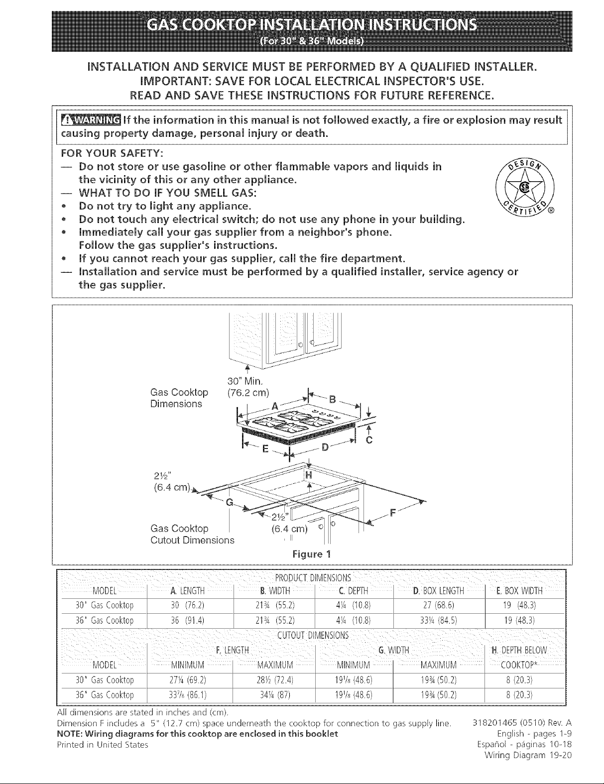
Gas Cooktop
Dimensions
21/2"
Gas Cooktop (6,4 cm) Q
Cutout Dimensions , u
Figure 1
30"GasCooktop 30 (76.2) 21sA552) 4_/4(10.8) 27(68.6) I9 (48.3)
36"GasCooktop 36 (91.4) 2134(55.2) 4_/4(10.8) 33_/4(84,5) 19(48.3)
30" GasCooktop 27_/4(69.2) 28_/2(72.4) 19Vs(48,6)
36" GasCooktop 34_A(87) 19Vs(48.6)
A[[ dimensions are stated in inches and (cm).
Dimension F includes a 5" (12,7 cm) space underneath the cooktop for connection to gas supply line.
NOTE: Wiring diagrams for this cooktop are enclosed in this booklet
Printed in United States
318201465 (0510) Rew A
Espafiol - pa'ginas 10=18
Wiring Diagram 19=20
English - pages 1@
Page 2
Important Notes to the Installer
1. Read all instructions contained in these installation
instructions before installing the cooktop.
2. Remove all packing material before connecting the
electrical supply to the cooktop.
3. Observe all governing codes and ordinances.
4. Be sure to leavethese instructions with tile consumer.
5. Note; For operation at 2000 ft. elevations above see
level, appliance rating shall be reduced by 4 percent
for each additional 1000 ft.
Important Note to the Consumer
Keep these instructions with your Useand Care Guide for
future reference.
IMPORTANT SAFETY
NS
Installation of this cooktop must conform with local codes
or, in the absence of local codes, with the National Fuel
Gas Code ANSI Z223.1/NFPA 54 in the United States, or
in Canada, with the Canadian Fuel Gas Code, CAN/CGA
B149 and CAN/CGA B149.2.
• When installed in a manufactured (mobile) home
installation must conform with the Manufactured Home
Construction and Safety Standard, title 24 CFR,part
3280 [Formerly the Federal Standard for Mobile Home
Construction and Safety, title 24, HUD (part 280)] or,
when such standard is not applicable, the Standard for
Manufactured Home Installation, ANSI/NCSBCS A225.1
or with local codes where applicable.
This cooktop has been design certified by CSA
International. As with any appliance using gas and
generating heat, there are certain safety precautions you
should follow. You will find them in the Useand Care
Guide, read it carefully.
• Be sure your cooktop is installed and grounded
properly by a qualified installer or service
technician.
• This cooktop must be electrically grounded in
accordance with local codes or, in their absence,
with the National Electrical Code ANSI/NFPA No.
70--latest edition in the United States, or in
Canada, with the Canadian EJectricat Code, CSA
C22.1 Part 1.
• The burners can be tit manually during an
electrical power outage. To light a burner, hold a
tit match to the burner head, then slowly turn the
Surface Control knob to UTE. Use caution when
lighting burners manually.
• Do not store items of interest to children in
cabinets above the cooktop° Children could be
seriously burned climbing on the cooktop to reach
items.
• To eliminate the need to reach over the surface
burners, cabinet storage space above the burners
should be avoided.
• Adjust surface burner flame size so it does not
extend beyond the edge of the cooking utensil.
Excessive flame is hazardous.
• Never use your cooktop for warming or heating
the room. Prolonged use of the cooktop without
adequate ventilation (.an be hazardous.
• Do not store or use gasoline or other flammable
vapors and liquids near this or any other
appliance. Explosions or fires could result.
The electrical power to the cooktop
must be shut off whiJe gas Jine connections are
being made. Faiture to do so couJd resutt in serious
injury or death.
Page 3
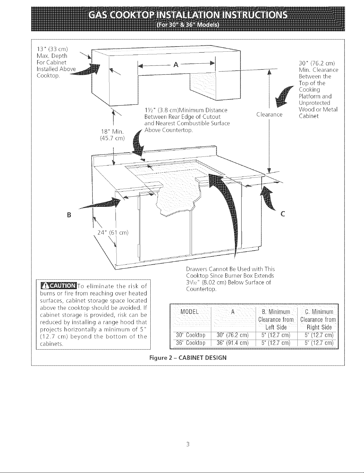
13" (33 cm)
Max, Depth
For Cabinet
Installed Above
Cooktop.
B
18" Min.
(45.7 cm)
A
lY2" (3.8 cm)Minimum Distance
Between RearEdge of Cutout
and Nearest Combustible Surface
Above Countertop.
Clearance
30" (76.2 cm)
Min. Clearance
Between the
Top of the
Cooking
Platform and
Unprotected
Wood or Metal
Cabinet
_To eliminate the risk of
burns or fire from reaching over heated
surfaces, cabinet storage space located
above the cooktop should be avoided. If
cabinet storage is provided, risk can be
reduced by installing a range hood that
projects horizontally a minimum of 5"
(I 2.7 cm) beyond the bottom of the
cabinets.
Drawers Cannot BeUsed with This
Cooktop Since Burner Box Extends
3Vs2" (8.02 cm) Below Surface of
Countertop.
Figure 2 - CABINET DESIGN
Page 4
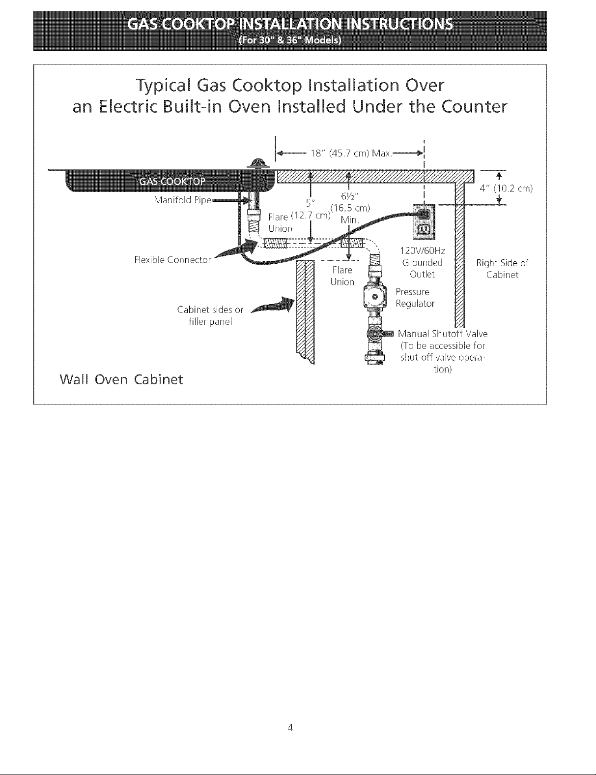
Typical Gas Cooktop Installation Over
an Electric Built-in Oven Installed Under the Counter
14_---- 18" (45.7 cm) Max.-----_
4" (10.2 cm)
Manifold Pi
61/2 ''
5" ,(16.5 cm)
Flare (12.7 cm) Min.
Union
÷
€
Wall Oven
Flexible Connector
Cabinet sides or
filler panel
Cabinet
120V/60Hz
Grounded
FlareUnion
/A
/A
Outlet
Pressure
Regulator
Manual Shutoff Valve
(To be accessible for
shut-off valve opera-
tion)
Right Side of
Cabinet
Page 5
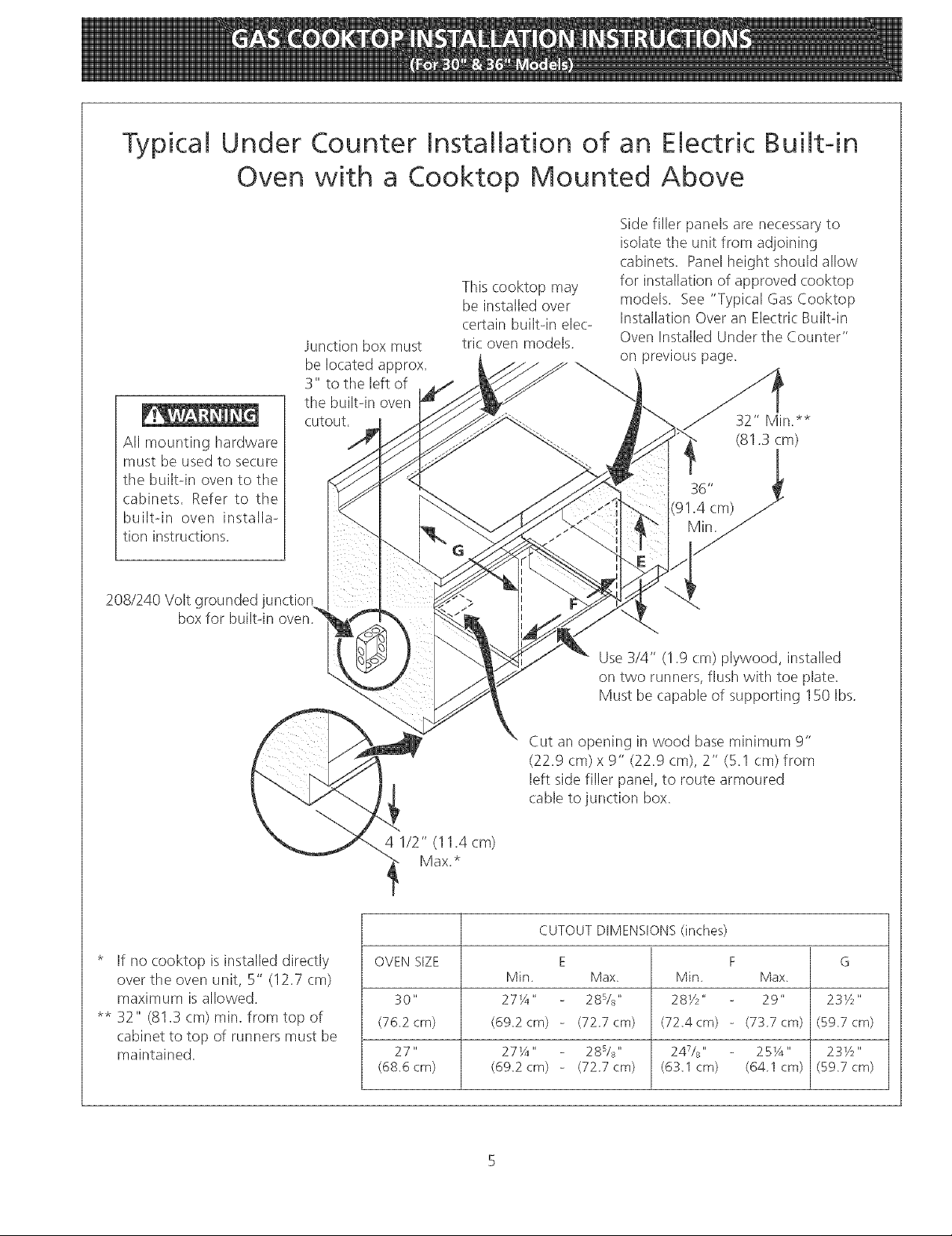
Typical Under Counter Installation of an Electric Built-in
Oven with a Cooktop Mounted Above
Side filler panels are necessary to
isolate the unit from adjoining
cabinets. Panel height should allow
for installation of approved cooktop
models. See "Typical Gas Cooktop
Installation Over an ElectricBuiltqn
Oven Installed Under the Counter"
on previous page.
32" Min.**
(81.3 cm)
36"
(91.4 cm)
All mounting hardware
must be used to secure
the builtqn oven to tile
cabinets. Refer to the
builtqn oven installa-
tion instructions.
208/240 Volt grounded junction
box for built-in
Junction box must
be located approx.
3" to the left of
the builtqn oven
cutout,
This cooktop may
be installed over
certain builtqn elee
tric oven models.
* If no cooktop is installed directly
over the oven unit, S" (12.7 cm)
maximum is allowed.
** 32" (81.3 cm) min. from top of
cabinet to top of runners must be
maintained.
Use 3/4" (1.9 cm) plywood, installed
on two runners, flush with toe plate.
Must be capable of supporting 150 Ibs.
Cut an opening in wood base minimum 9"
(22.9 cm) x 9" (22.9 cm), 2" (5.1 cm) from
left side filler panel, to route armoured
(.ableto junction box.
4 1/2" (11.4 cm)
Max.*
CUTOUT DIMENSIONS (inches)
OVEN SIZE E F G
Min Max, Min Max,
30" 27¼" 28s/_" 281/2" 29" 23Y2"
(76,2cm) (69,2cm) - (727cm) (72,4cm) - (737cm) (59,7cm)
27" 27¼" 28s/_" 24V8" 25¼" 23Y2"
(68,6crn) (69,2crn) - (727cm) (63,1cm) (641cm) (59,7cm)
Page 6
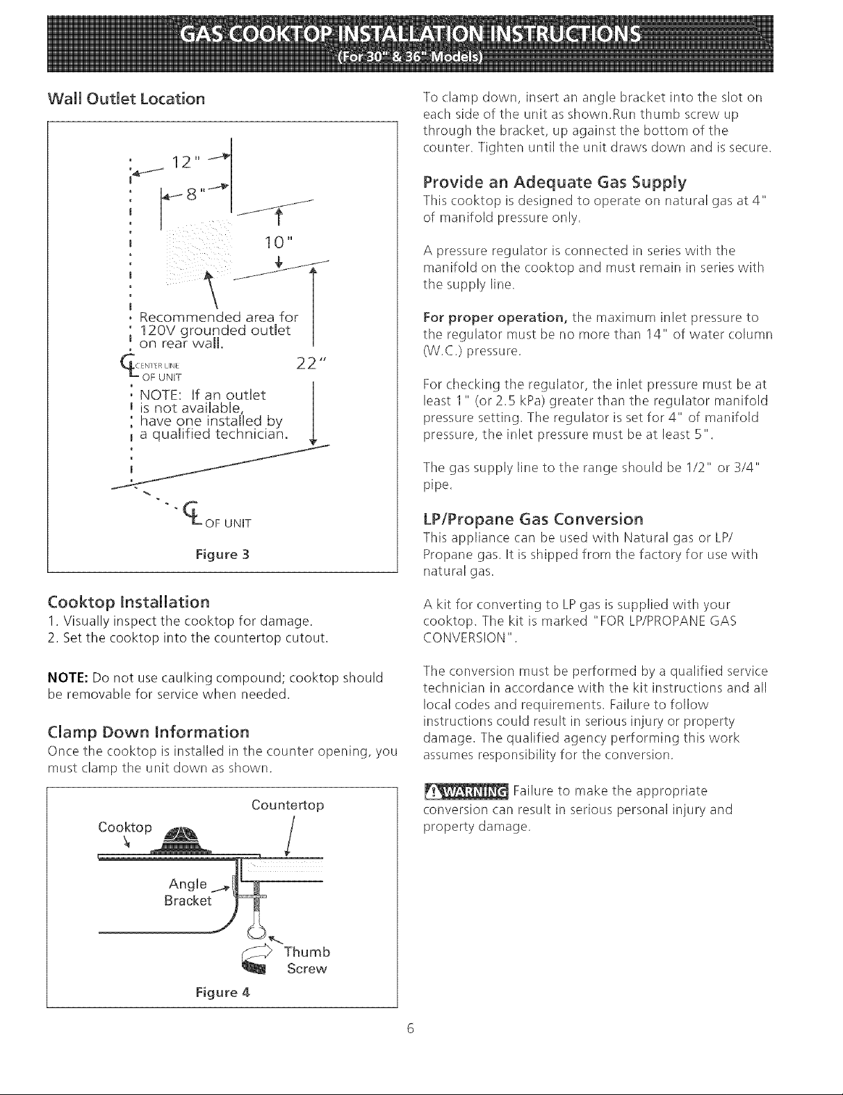
Wail Outlet Location
_12" 4
To clamp down, insert an angle bracket into the slot on
each side of the unit as shown.Run thumb screw up
through tile bracket, up against the bottom of the
counter. Tighten until the unit draws down and issecure.
Provide an Adequate Gas Supply
This (ooktop isdesigned to operate on natural gas at 4"
of manifold pressure only.
10"
A pressure regulator is connected in series with the
manifold on the cooktop and must remain in series with
tile supply line.
Recommended area for
12OV grounded outlet
on rear wall.
22"
: NOTE: If an outlet
is not available, [
have one installed by
_ a qualified technician.
½
OF UNIT
Figure 3
Cooktop Installation
1. Visually inspect the cooktop for damage.
2. Set the cooktop into the countertop cutout.
NOTE: Do not use caulking compound; cooktop should
be removable for service when needed.
Clamp Down Information
Once the cooktop is installed in the counter opening, you
must (.lamp the unit down as shown.
Counte_op
For proper operation, the maximum inlet pressure to
the regulator must be no more than 14" of water column
(W.C.) pressure.
For checking the regulator, the inlet pressure must be at
least I" (or 2.5 kPa) greater than the regulator manifold
pressure setting. The regulator is set for 4" of manifold
pressure, the inlet pressure must be at least 5".
Tile gas supply line to tile range should be 1/2" or 3/4"
pipe.
LP/Propane Gas Conversion
This appliance can be used with Natural gas or LP/
Propane gas. It is shipped from the factory for use with
natural gas.
A kit for converting to LPgas is supplied with your
cooktop. The kit is marked "FOR LP/PROPANEGAS
CONVERSION".
The conversion must be performed by a qualified service
technician in accordance with the kit instructions and all
local codes and requirements. Failure to follow
instructions could result in serious injury or property
damage. The qualified agency performing this work
assumes responsibility for the conversion.
Failure to make the appropriate
conversion can result in serious personal injury and
property damage.
Figure 4
Thumb
Screw
Page 7

Important: Removeallpackingmaterialand
literaturefromcooktopbeforeconnectinggasand
electricalsupplytocooktop.
Install Pressure Regulator
Install tile pressure regulator with the arrow on the
regulator pointing up toward the unit in a position where
you can reach the access cap.
Do not make the connection too tight.
The regulator is die cast. Overtightening may crack the
regulator resulting in agas leak and possible fire or
explosion.
Manual GAS FLOW Pressure
Shutoff Flare _€_ Flare Regulator
Valve Union Union
1 $
N,pp,e He×, ,e
Off Connector Access
Cap
All connections must be wrench4ightened
Figure 5
Assemble the flexible connector from tile gas supply pipe
to tile pressure regulator in the following order:
1. manual shutoff valve
2. 1/2" (1.3 cm) nipple
3. 1/2" (!.3 cm) flare union adapter
4. flexible connector
5. 1/2"' (1.3 cm) flare union adapter
6. 1/2" (!.3 cm) nipple
7. pressure regulator
Use pipe-joint compound made for use with Natural and
LP/Propane gas to seal all gas connections. If flexible
connectors are used, be certain connectors are not
kinked.
The supply line must be equipped with an approved
manual shutoff valve. This valve should be located in the
same room as tile cooktop and should be in a location
that allows ease of opening and closing. Do not block
access to the shutoff valve. The valve is for turning on or
shutting off gas to the appliance.
Shutoff Valve -
Open position
Figure 6
Once regulator is in place, open the shutoff valve in the
gas supply line. Wait a few minutes for gas to move
through the gas line.
Check for leaks. After connecting the cooktop to the
gas supply, check the system for leaks with a
manometer. If a manometer is not available, turn on the
gas supply and use a liquid leak detector (or soap and
water) at all joints and connections to check for leaks.
Do not use a flame to check for leaks
from gas connections. Checking for leaks with a flame
may result in a fire or explosion.
Tighten all connections if necessary to prevent gas
leakage in the cooktop or supply line.
Check alignment of control knob valves after
connecting the cooktop to the gas supply to be sure the
cooktop manifold pipe has not moved. A misalignment
could cause tile valve stems to rub on the control panel,
resulting in a gas leak at tile valve.
Disconnect this cooktop and its individual manual
shutoff vatve from tile gas supply piping system during
any pressure testing of that system at test pressures
greater than 1/2 psig (3.5 kPa or 14"water column).
Isolate the cooktop from the gas supply piping
system by (:losing its individual manual shutoff valve
during any pressure testing of the gas supply piping
system at test pressures equal to or less than 1/2 psig
(3.5 kPa or 14"' water column).
Page 8

Electrical Requirements
120 volt, 60 Hertz, properly grounded branch circuit
protected by a I 5 amp circuit breaker or time delay fuse.
Do not use an extension cord with this cooktop.
Check Operation
Refer to the Use and Care Guide packaged with the
cooktop for operating instructions and for care and
cleaning of your cooktop.
Grounding instructions
IMPORTANT Please read carefully.
For persona[ safety, this appliance must be properly
grounded.
The power cord of this appliance isequipped with a 3-
prong (grounding) plug which mates with a standard 3-
prong grounding wall receptacle (see Figure 7) to
minimize the possibility of electric, shock hazard from the
appliance.
The wall receptacle and circuit should be checked by a
qualified electrician to make sure the receptacle is
properly grounded.
Preferred Method
Grounding type
wall receptacle
not, under any
circumstances, cut,
remove, or bypass
the grounding
prong.
Do not touch the burners. They may be hot enough to
cause burns.
.
Instal[ Burner Caps
This cooktop is equipped with sealed burners as
shown (see Figure 8).
A. Unpack your burner heads and burner caps.
B. Place burner head over each gas orifice,
matching the head with the orifice size. Be
careful not to damage the electrode while
placing the head over the orifice. Make sure
electrode fits correctly into slot in burner head.
C. Place a burner cap on each burner head,
matching the cap size to tile head size. Each
burner cap has an inner locating ring which
centers the cap correctly on the burner head.
D. Be sure that all the burner caps and burner
heads are correctly placed BEFOREusing your
cooktop.
Power supply cord with 3-
prong grounding plug.
Figure 7
Where a standard 2-prong wall receptacle is installed, it
is the personal responsibility and obligation of the
consumer to have it replaced by a properly' grounded 3-
prong wall receptacle.
Do not, under any drcumstances, cut or remove the
third (ground) prong from the power cord.
Disconnect electrical supply cord from
wall receptacle before servicing cooktop.
Burner Ca[
Burner Head
Figure 8
NOTE: There are no burner adjustments necessary on
this cooktop.
Page 9

2. Turn on EJectricat Power and Open Main Shutoff
Gas Valve
3_
Check the igniters
Operation of electric: igniters should be checked after
cooktop and supply line connectors have been
carefully checked for leaks and the cooktop has
been connected to electric power.
To operate the surface burner:
A. Push in and turn a surface burner knob to the
LITE position. You will hear a small ticking noise;
this isthe sound of the electric, ignitor which
lights the burner.
B. After the burner lights, turn to the desired flame
size. The controls do not have to be set at a
particular mark. Use the marks as a guide and
adjust the flame as needed.
Hollow
Valve Stem_
Figure 9
4_
Adjust the "LO"' or "SIMMER" Setting of Surface
Burner Valves (see Figure 9)
Push in and turn each control knob to tile "LO" (or
"SIMMER") setting. The"LO" setting of each
burner has been set at the factory to the lowest
setting available to provide reliable reignition of the
burner. If it does not stay lit on the"LO" setting,
check the setting as follows.
_Be careful when performing this
operation.
A. Allow cooktop to cool to room temperature.
B. Light all burners by turning each control knob to
LITEuntil burners ignite, and then set them at
"HI".
C. _turn the knob of the burner you want to
adjust to tile LOWEST POSITION.
D. If burner goes out, readjust valve asfollows:
Remove the surface burner control knob, insert a
thin-bladed screw driver into the hollow valve
stem and engage the slotted screw inside. Flame
size can be increased or decreased with the turn
of the screw. To increase flame size turn the
screw counterclockwise and to decrease turn
clockwise. Adjust flame until you can quickly
turn knob from HI to LOWESTPOSITIONwithout
extinguishing the flame. Flame should be as
small as possible without going out.
E. If you need to adjust another burner, repeat the
steps from A to D above until all burners operate
properly.
When All Hookups are Complete
Make sure all controls are left in the OFFposition.
Make sure the flow of combustion and ventilation air to
the cooktop is unobstructed.
Model and Serial Number Location
The serial plate is located on the underside of the
cooktop.
When ordering parts for or making inquires about your
range, always be sure to include the model and serial
numbers and a lot number or letter from the serial plate
of your cooktop.
Your serial plate also tells you the rating of the burners,
the type of fuel and the pressure the cooktop was
adjusted for when it left the factory.
Before You Call for Service
Read the Before You Call for Service Checklist and
operating instructions in your Use and Care Guide. It
may save you time and expense. The list includes
common occurrences that are not the result of defective
workmanship or materials in this appliance.
Refer to your Use and Care Guide for Sears service
phone numbers, or call 1-800-4-MY-HOMI:®.
Page 10

LA INSTALACI6N Y EL SERVICIO DEBEN SER REAUZADOS POR UN INSTALADOR CAUNCADO.
IMPORTANTE: GUARDE ESTAS INSTRUCGONES PARA USO DEL INSPECTOR ELECTR_CO LOCAL
LEA Y GUARDE ESTAS INSTRUCCIONES PARA FUTURAS REFERENCIAS
ocurrir incendios o expmosiones que pueden causar daSos materiaies, iesiones o ia rnuerteo
__ Si todas ias instrucciones de _ste manual no son observadas a ia ietra, se puede
PARA SU SEGURIDAD: /_
-- No alrnacene o utilke gasolina u otros vapores y liquidos inflamables cerca
de _ste o cualquier otto artefacto.
-- QUE HACER SmHAY FUGAS DE GAS :
No intente de encender ningun artefacto
No toque ningun interruptor el6ctrko; no utilke ningun aparato t616fonko en su edifido.
• Marne inmediatarnente e[ abastecedor de gas desde e[ te[_fono de un vecino. Siga [as
instrucciones del abastecedor de gas.
En caso que no puede contactar el abastecedor de gas llame al departamento de bomberos.
--La instalad6n y el servicio t_lefonico deben set realizados pot un instalador calificado, pot un
servicio tecnico certificado o pot el abastecedor de gas.
30" M_n.
Dimensiones
de ia parriiia
de cocinar
21/2 _
(6.4
(76.2 cm) _ B
Dimensiones
del hueco de (6.4 cm) ®
ia parriiia de cocinar
, II
Figura 1
A ALTURA B,ANCHURA C PROFUNDIDADD. LARGODELACAJAE,ANCHODELACAJA
Modelo30"
Modelo36"
30 (76.2) 213A(55.2) 4_/4(10.8) 27(68.6) I9 (48.3)
36 (91.4) 213A(55.2) 4_/4(10.8) 33_/4(84.5) I9 (48.3)
MODELO, MINIMA MAXIMA i MINIMA DEBAJODELAESTUFA*
Modelo30" 271/4(69.2) 281/2(72.4) 191/8(48.6) 19SA(50.2) 8 (20.3)
Modelo36" 337/s(86.I) 34_/4(87) 191/8(48.6) 19SA(50.2) 8 (20.3)
Todas las dimensiones se dan en pulgasdas (cm),
La dimension F incluye un espa(io de 5" por debajo de la plancha de cocinar para la conexi6n
de la I[nea de suministro de gas. English - pages 1-9
NOTA: Se adjunta los diagrarnas de cables de esta ptancha de cocinar con et tibreta, Espanol - p_iginas 10-18
Imprimido en los Estados Unidos Diagrama de la instalaci6n abimbrica 19-20
318201465 (O510) Rev A
Page 11

Notas importantes para el instalador:
1. Leatodas las instrucciones de instalaciOn antes de
realizar la instalaci6n de la plancha de cocinar.
2. Retire todos los artlculos de embalaje antes de realizar
las conexiones electricas a la plancha de cocinar.
3. Observe todos los codigos o reglamentos estatales
4. AsegL_reseque el consumidor tenga estas instrucciones.
5. Nota: Parael corredo funcionamiento en lugares
superiores a los 2000 ft, el regimen del mecanismo
debe reducirse un 4% pot cada 1000 ft sobre el nivel
del mar.
Notas importantes para el consumidor
Guarde todas lasinstrucciones con su manual del usuario
para futuras referiencias.
INSTRUCCIONES DE
SEGURIDAD IMPORTANTES
La instala(ic_n de esta plancha de cocinar debe realizarse
en conformidad con los codigos locales o, si estos no
existen, (:on el National Fuel Gas Code ANS! Z223.1/NFPA
54 en los Estados Unidos, o en Canada, con el Canadian
Fuel Gas Code, CAN/CGA B149 y CAN/CGA B149.2.
• La instalacion de aparatos disefiados para instalacion
en casas prefabricadas (moviles) debe conformar con el
Maufactured Home Consturction and Safer Standard,
titulo 24CFR, parte 3280 [Anteriormente el Federal
Standard for Mobil Home Construction and Safety,
tltulo 24, HUD (parte 280)] o cuando tal estandar no se
aplica, el Standard fo Manufactured Home Installation,
ANS!/NCSBCS 225.1, o con los c6digos locales.
El diseFio de esta plancha de cocinar cuenta con la
aprobaci6n de la CSA interna(ional. AI igual que todos los
artefactos a gas que generan calor, deben seguirse ciertas
medidas de seguridad. Vienen con el Manual del Usuario.
Lea atentamente el manual.
• AsegQrese que ta plancha de codnar sea instalada
y puesta a tierra correctamente pot un instalador
o t_cnico calificado.
• La plancha de cocinar debe conectarse
el_ctricamente a tierra de acuerdo con los c6digos
locates o, de no existir, con et c6digo eI6ctrico
ANSt/NFPA No. 70 - Qitima edid6n en los Estados
Unidos, or in Canada, con e[ Canadian Electrical
Code, CSA C22.1 Parte !.
• Los quemadores pueden encenderse manualmente
durante una interrupci6n det sum[n[stro el_ctrko.
Para encender un quemador, mantenga un f6sforo
encendido en el extremo de! quemador, tuego
gire suavemente la perilla basra MTE (encendido).
Tenga cuidado at encender tos quemadores en
forma manual.
• No deje art_culos que interesan los ni_os en los
armarios que est_n sobre [a [a plancha de cocinar.
Les podNa causar quemaduras graves si intentan
subirse para alcanzarlos.
• Para eliminar el riesgo de extender pot endma de
los quemadores superlores, deberla evitar el
espado de aimacenam[ento det armario,
[oca[izado pot endma de estos quemadores
• Gradue e[ tamaffo de [a llama de modo que no
sobrepase el borde del utens[[[o de codna.
Demasiada llama es peligrosa.
• No utiIice jam&s la codna como caIefactor. El uso
prolongado de la cocina sin la ventilaci6n adecuada
puede set peligroso.
• Mantenga el _rea cerca de este artefacto o de
cualquier otto artefacto despejada de sustancias
combustibles, gasolina y otros [[quidos
inflamables. Se puede ocurrir incendios o
explosiones.
E[ sum[n[stro e[_ctr[co a ta p[ancha
de codnar debe de set cerrado durante [as
conexiones a [a t[nea. De to contrar[o se puede
resuItar [esiones graves o [a muerte.
11
Page 12

Max.profundidad
degabinetes
instaladospor
encimadela
planchade
empotares13"
(33cm).
B
/
18"Min.
(45.7cm)
24" cm)
A
I
11/2"(3.8 cm) Minimo Distancia
entre el borde posterior del
hueco y lamas cerca superficie
combustible por encima del
mostrador.
Espacio
30" (76.2 cm)
M[nimo de
espacio entre
la parte
superio de la
plataforma de
la plancha de
cocinar y el
fondo de una
madera non
protegida o
armario
rae_allCO
\
_!_ Para eliminar el riesgo de
alargar sobre los unidades en calentamiento
de la superficie, deberia evitarse el espacio
de almacenamiento del armario, ubicado
sobre las unidades de la superficie. Si se
cuenta con este espacio, se puede disminuir
el peligro instalando una cubierta de cocina
que se extienda horizontalmente en 5" (12.7
cm) mfnimo pot sobre la parte inferior
delantera en los armarios.
Figura 2 - DESENO DEL ARMARtO
No es posible utilisar caiones con
esta parrilla de cocinar porque la
caja de empalme se extiende de
3s/s2" (8.02 cm) pot encima de la
superficie del mostrador.
A I B:ESPai!0 I c:ESP !O
PLANCHADEI Imiuirrmdes@ d l minim0 des@
COCtNARDE I Itado izquierdo leltadoderecho
3£ Cooktop I 3£ (762 cm) I 5" (12# cm) I 5" (12# cm)
36" Cooktop 1 36" (91.4cm) 1 5" (12# cm) I 5" (12# cm)
12
Page 13

lnstalaci6n tipica de [a plancha de codnar a gas por endma de un
horno electrico empotrado instalado deba]o de[ mostrador
Tubo mOIti
Conector
Cabinet sides or
filler panel
Armario del homo de pared
(!2.7 cm) Min.
Uni6n
18" (45.7 cm)Max.----_ I
61/2"
5" (13.5 cm)
'"" Uni6n
Uni6n Toma de
/A
_j regulador de
corriente a tierra
presi6n
(Debe de set accessible para el
funciona-miento de la valvula de
n
i
120V/60Hz
V_lvula de cierre manual
÷
4" (10.2cm)
Lado derecho
del armario
cierre)
13
Page 14

Tipica insta[aci6n de un homo e[ectrico empotrado con una
p[ancha de cocinar pot encima
Entreparhos Ilenador de lados son
necesarios para aislar el aparato de los
armarios adyacentes La altura de panel
Todas las fijaciones de
montaje deben de estar
utilizadas para sujetar el
homo empotrado a los
armarios Refiere a [as
instrucciones de
instalacion del homo
empotrado.
Esta plancha de cocinar puede instaJarse
por encima de algunos modeJos de homo
eJ6ctrico empotrado
Aproximadamente 3"
(76 cm)
debe de permitir la instaJaci6n de
modelos de planchas de cocinar
aprobantes. Ver "lnstalaci6n tfpica de
plancha de cocinar a gas pot encima de
un homo el6ctrico empotrado instaJado
deba]o de[ mostrador" en la pagina 4.
32" (81.3 cm)
Minimo **
Caja de empalme a tierra de
208/240 voltaje para homo
empotrado
* (Si no hay plancha de cocinar
instalada directamente sobre el
aparato, un maximo de 5" (12.7
cm) esta permitido)
** Un minimo de 32" (81.3 cm)
desde la parte superior del
armario hasta la parte superior de
las ruedas debe de set mantenido.
Utilice 3/4" (1 9 cm) de madera
contrachapada, instalada sobre 2 ruedas,
perpendicular a una cima de contorno de
pJaca. Debe de poder sostener 150 [bs
_ orte una abertura en la basa de
madera mfnimo 9" (229 cm) x 9"
(22.9 crn), 2" (El cm) de[ entrepano
[[enador izquierdo, para conducir el
cable blindado a [a caja de empalme.
DIMENSIONES DEL HUECO (pulgadas)
Tamaflo E F G
del homo Mfn. M_ix M[n. Ma'x
30" 27¼ " 28sA '' 281/2 " 29 " 231/2"
(762cm) (692cm) - (727cm) (724cm) - (73/7cm) (597cm)
27" 27¼" 28%" 24V8" 2Sh" 2 SW2"
(686cm) (692cm)- (727cm) (631cm) (64,1cm) (597cm)
14
Page 15

Ubicad6n de [a toma de corriente de [a pared
1 2 II
' I_ 8'__4_ /I
I J--J_"
e 10"
Para ajustar el aparato, inserte la consola de escuadra, con
el lado desviado,en las ranuras en cada lado del aparato.
El tornillo de orejas debe entonces de pasar a trav6s del
soporte y hasta la parte de abajo del mostrador. Apri_telo
hasta que el aparato sequede ajustado.
Provea un adecuado suministro de gas
Esta plancha de cocinar est_ disefiada para utilizar gas
natural de 4" de presi6n m01tiple solamente.
J
, Area recomendada Fatoma de
corriente a tierra de 120V en
B la pared posterior
APARATO
_DEL Z2"
' NOTA: Si no existe una toma
mde corrlente, co_tacte a un
electrlcista callficado para
mrealizar [a b_stalaciOn.
" _DEL APARATO
Figura 3
Instaladon de la plancha de coccinar
1. Examine visualmente la plancha de cocinar para saber
si hay daho.
2. Fije el la plancha de cocinar en el recorte del
mostrador.
Informaci6n para sujetar el aparato
Una vez que el aparato esta instalado en la apertura del
mostrador, setiene que sujetar como se indica.
Cinta de Mostrador
Planchadecocinar _ esponja /
Se conecta un regulador de presion en serie al multiple de
la plancha de cocinar y debe permanecer en serie con la
Ilnea de suministro de gas.
Para que manejo correcto, la presi6n de entrada
m_xima ha(ia el regulador no debe exceder 14" de
presion de la columna de agua.
Para controlar el regulador, la presi6n de entrada debe set
de al menos I" (o 2.5 Kpa) mayor que el ajuste de la
presi6ndelmQItipledelregulador. EIreguladorseajustaa
4" de la presi6n del m01tiple, la presion de entrada debe
de set de al menos 5".
La Ilnea de suministro de gas por el horno deberla tener un
tubo de 1/2" o de 3/4".
Conversion de gas propano/licuado
Esta plancha de cocinar ha sido dise¢iada para utilizar gas
naturalogaspropano. Hasidofijadaenlaf_bricapara
utilizarse con gas natural.
Si desea hacer la conversion para utilizar el gas propano,
use laspiezas con orificios fijados provitos en el paquete
del manual de instrucciones para la instalacion en el
paquete escrito "PARA LA CONVERSIONEN GAS
PROPANO". Siga lasinstrucciones que estan con los
orificios.
Para hater la conversi6n del gas natural al gas propano, es
necesario utilizar el servicio de un t6cnico calificado, in
acuerdo con lasinstrucciones del fabricante y todos los
c6digos I/reglamentos reguladores. Si todas las
instrucciones no son observadas, se puede ocurrir severos
lesiones o dafios materiales. La agencia calificada que
hate el trabajo asuma la responsabilidad para la
conversion.
ConsoJa de escuadra
Figura 4
Tornillo de
orejas
Si la conversi6n apropiada no esta
observada, se puede ocurrir severos lesiones o da_os
materiales.
Importante: Retire todos los artlculos de embalaje y
folletos de la cocina antes de realizar lasconexiones de gas
y electricas a la cocina.
15
Page 16

InstaJad6n deJ reguJador de presi6n
Instale el regulador de presiOn con la fie(ha del regulador
apuntando hacia la unidad en una posiciOn que permita
alcanzar la tapa de entrada.
No ajuste demasiado la conexiOn. El
regular esta fundida a presiOn. AI ajustar demasiado se
puede romper el regulador c:ausando una fuga de gas y
un posible incendio o explosion.
Valvula de FLUJO_DELGAS Regulator
cierre Uni6n Uni6n de presi6n
manual
Abler |
(on) \-._ Boquilla Conector Boquilla_
Apagado flexible Tapa de
(off) entrada
Todas las conexiones deben ajustarse con
una Ilave de tuerca
Figura 5
Monte el cone(tot flexible del tubo del suministro de gas
al regulador de presi0n enfuncionamiento:
I. v_lvula de cierre manual
2. boquilla de 1/2" (1.3 cm)
3. adaptor de 1/2" (I .3 cm)
4. cone(tot flexible
5. adaptator de 1/2" (I .3 cm)
6. boquilla de I/2" (! .3 cm)
7. regulador de presi6n.
Utilice un compuesto de tubo articulado para uso de gas
natural y propano para sellar todas las c:onexionesde gas.
Si se utilizan cone(totes flexibles, aseg0rese que los
conectores no estAn torcidos.
El tubo de suministro de gas debreria incluir una valvula de
cierre certificada. Esta valvula deberia estar ubicada en la
misma habitaci61n de la plan(ha de coninar y deberia estar
en un lugar que permita una abertura y cierre fac:iles. No
bloquee las entradas de la valvula de cierre. La valwJla
sirve para abrir o cerrar el paso del gas al artefacto.
AbJerta
Figura 6
Abra la v_lvula de cierre en el tubo de suministro de gas.
Espere unos minutos para que el gas pase a traves del
tubo de gas.
Verifique si hay fugas. Luego de conectar la cocina al
gas, verifiqueelsistemaconunmanOmetro. Sinocuenta
con 6ste instrumento, de lavuelta al suministro de gas de
la (:ocina y utilice un detector de fugas Ilquidas (o agua y
jab6n) en todas las articulaciones y conexiones para
verificar si existen fugas.
No use ningOn tipo de llama para
verificar si hay fugas de gas, Verifique si hay fugas con
una llama puede occasionar incendio o explosi6n,
Ajuste todas [as conexiones en caso que sea necesario,
para evitar fugas de gas en la cocina o en el tubo de
sumininistro de gas.
Verifique ta alineaci6n de [as v&[vulas luego de
cone(tar la plan(ha de cocinar al suministro de gas para
asegurar que no se ha movido la valwJla del m01tiple de la
plan(ha de cocinar.
Desconecte ta cocina y su v_lvula de cierre individual
del sistema de tubefia del suministro de gas durante
cualquier ensayo de presion del sistema en ensayos de
presiOn superiores a 1/2 psig (3.5 kPa o 14" colomna de
agua).
Aparte ta cocina de[ sistema de tubeda del suministro
de gas cierrando su vglvula de cierre individual manual,
durante cualquier ensayo de presion del systema de
suministro de gas en ensayos iguales o inferiores a 1/2 psig
(3.5 kPao 14" colomna de agua).
16
Page 17

Requerimientos el_ctricos:
Uncircuitoderivadoconectadocorrectamenteatierrade
120voltios,60Herzprotegidoporuninterruptor
automa'ticode15ampounfusiblederetardo.Noutilke
uncable flexible de extensi6n en esta plancha de
codnar.
[nstrucdones para [a puesta a tierra
tMPORTANTE Por favor, lea atentamente.
Como medida de seguridad persona], est_ artefacto
debe conectarse a tierra correctamente.
El cable de encendido de este artefacto incluye un
enchufe de tres patas (a tierra) que calza con un enchufe
de pared de tres patas de conexi6n a tierra (ver Figura 7)
para disminuir la posibilidad de peligro de cheques
electricos desde el artefacto.
Un electricista calificado debe verificar el enchufe de pared
y el circuito para asegurar que el enchufe est& conectado a
tierra correctamente.
Verifique la operad6n
Refiera al Manual del Usuario que viene con la plancha de
cocinar para las instrucciones de funcionamiento y el
mantenimiento y la limpieza de su plancha de cocinar.
No toque a los quemadores. Pueden estar suficientemente
calientes par causar quemaduras.
1. tnstalad6n de tas tapas de quemadores
Esta plancha de cocinar est_ equipada con quemadores
sellados como semuestra (Figura 8)
MI_TODO PREFERIDO
Enchure de
pared atierra
ba
Cab[o de encendido
con enchufe de tres
patas a tierra
Figura 7
En caso de encontrarse con un enchufe de pared de dos
patas, es la personal responsibilidad y la obligaci6n del
consumidor reemplazarlo por el enchufe de pared a tierra
de tres patas correspondiente.
No debe, bajo ninguna circunstanda cortar o ret[rar [a
tercera pata (tierra) de[ cable de encend[do
Desconecte el cable del suministro
electrico del enchufe de pared antes de reparar la
plancha de cocinar.
Base del Abert_r_
quemadore
as
Electrodo
Figura 8
A. Desembale lastapas de los quemadores y las bases.
B. Coloque las basas de quemador sobre cada tubo de
abertura de gas.
C. Aseg0rese que el quemador est_ correctamente
alineadoynivelado. Coloquecadatapadel
quemador debajo de cada base del quemador.
NOTA: No es necesario realizar ajustes en los quemadores
de esta plancha de cocinar.
2. Abre e[ sumin[stro e[_ctdco y ta v_lvula de derre
principal de[ gas.
17
Page 18

3. Verifique [os dispositivos de encendido
La manipulaci6n de los dispositivos de encendido
electri(o deberia verificarse tras haber revisado
detenidamente la plancha de (ocinar y los conectores
del tubo del suministro de fugas y tras haber conectado
la plancha de cocinar al suministro electrico.
Para operar en la superfide de[ quemador:
A. Presione y gire la perilla de control hasta LITE.Se
escuchara aun pequefio ruido. Este esel ruido
producido por el dispositivo de encendido electrico
cuando enciende el quemador.
B. Una vez que el quemador estA encendido, gire
hasta obtener el tamafio de la llama deseada. No
es necesario ajustar los controles en una marca
determinada. Uselas marcas como gula y ajuste la
llama segOn se desea.
4. Verifique el ajuste "LO" O "SIMMER" de las
v_lvulas de superfide de quemador (vet Figura 9)
Presione y gire el bot6n de control al ajuste "LO" (o
"SIMMER").EI ajuste "LO" de cada quemador ha sido
creado en la f_bri(a para fijarse al menor ajuste
disponible para entregar un reen(endido (onfiable del
quemador. Si no queda encendido en el ajuste "LO",
verifique el ajuste "LO" como se muestra a
continuaci6n.
A. Deje que la cocina se enfr[e a temperatura
ambiente.
B. Enciende todos losquemadores girando cada bot6n
de control hasta LITEpara encender los quemadores
y fijarlos en "HI".
C. Gire r_pidamente el quemador hasta LOWEST
POSITION.
D. Sielquemadorseapaga, reajustelav_lvula como
se muestra a continuaci6n:
Retire el boton de control del quemador, inserte un
destornillador de cuchillo delgado en el v_stago del
agujero de la valvula y encaje el tornillo ranurado. El
tamafio de lallama se puede aumentar o disminuir
girando el tornillo. Gradue la llama hasta que se
pueda girar rapidamente hacia abajo desde HI hasta
LOWEST POSITIONsin apagar la llama. La llama
debefia ser Io mas baja posible y estable sin
apagarse.
E. Sise desea ajustar otro quemador, repita los pasos
de A a D descritos hasta que los quemadores
funcionen correctamente.
El hueco del
vastago de la
v&lvula I _._..,._
F[gura 9
Cuando se hart realizado todos los sistemas
de conexi on
Aseg@reseque todos los controios estan en la posici6n de
OFF(apagado).
AsegOrese que el flujo de combusti on y ventilaci6n de aire
de la cocina no estan obstruidos
Modeio y ubicad6n dei n_mero de serie
La placa de n@merode serie est_ ubicada en el lado de
abajo de la caja de quemadores.
AsegOrese de incluir el modelo, n@merode serie y el
nOmero o letra del Iote que se encuentran en la placa, en
todo pedido de partes o solicitud de informaci6n acerca de
su plancha de co(inar.
La placa de nOmero de serie tambien indica las
especificaciones de los quemadores, el tipo de combustible
y la presi6n para la cua[ fu6 ajustada la plancha de cocinar
en la f_brica.
Antes de [[amar a[ servido
Lea la se(ci6n Lista de Control de Aver[as en su Manual
delUsuario. Estolepodr_ahorrartiempoygastos. Esta
lista inciuye ocurrencias comunes que no son el resultado
de defectos de materiales o fabricacion de este
artefacto.
Lea la garantia y la informaci6n sobre el servicio en su
Manual del Usuario para obtener el nqmero de telefono
y la dirreci6n del servicio o Ilamar 1-888-SU-HOGAR sM.
Por favor Ilame o escriba si tiene preguntas acerca de su
estufa o necesita repuestos.
18
Page 19

TOP 8bRNER IGn. ITER
OPTIONAL
CUENADOR DE ENCEND_DO SUPERIOR
OPCIONAL
SOUG!E 0"ALLUMAGE-BRULEUR
OPTIONP%
OUEMABOR DE ENCENDIB_ SUPERIOR
OPCJON_
BBL_IE D'ALLUMA_BRULEUR
FACULTATIF
TOP BU_?NER iGNITER /_]:_ /
TOP BU_rR IGNITER
OBEMADOR _ ENCENDIDO SUPERIOR
BOUGIE D'ALLUMAGE-BRULEUR
TOP BURNER IGNITER
OUEMADCR BE ENDENDID© SUPERiBR
BObblE D'ALLUMAGE _LEbR
_b
B]_@N_CT PO_ER BEFORE SERVICING UNiT
0ESCONECTE LA E_RG}A ANTES BE REALIZAR
EL HANTENIHIENIO 0EL ELECTROOONESllDO
AVFRTISBENENT
COLDER LE D0t_ANT AVANT 0'EFFECTbTR LA
REPARATION¸
CBtOR CODE / COBICxO_ DE C OR / CODE COCLEUR
B_ BLACK / NEGRO / NO IR
_HITE / _A_',CO / _ANC
w
NC_
?Ss
GROUND
Pb_STA A TIERRA
HiSE A LA TERRE
IGNS_
INTEN(:TRASERO
DEREOQ
I RIGHT REAR
INTERALLUM
DAR
8K _
] GN S/4
]NT END TRASERO
] ZOU IERDO
]NTER ALLUM
LEFT REAR
GAR
BK_I
INTEND DE
FRENTE IZOU[ERBO
INTERALLUN
LEFT FRONT
G AV
]GN BW
]NTENS BE
FRENTE C_RECHO
]NTER ALLUM
I RIGql FRONt
D AV
EHPALME
CONN£CTEUR
_ CONNPCTOR
POWER CORD
PARA TRANSPORTE
0E PUERZA
CABLE
O'ALIMENTAT_ON
2 18 200
iWIRE GAGE
i ALAMBRE MEDIDA TEMP'C
L/
RIGHT FRONT _EFT FRONT LEFT REAR
]QNSW iGNBW IGNSW
]NT END DE _NTEN_ BF _NTENCTRASERO
_NTE OERECHO _RENTE IZOUEERDO IZOUIERDO
]NTERALLUH iNTERALLUH INTERA_LUH
DAV GAV BAR
TBP R'ORNER IGNITER
OUEK_DOR DE ENCENOI_ S_ERIBR
ROUGiE D'ALLOMAGE BR_JLEUR _ _
TOP BURNER I GN _TEA
OUEPt_DOR DE ENCENDIDO SCPER OR
TBP BURNER iGNITER
OUEMABOR DE ENCENDIDO SUPERIOR
BOUG,E D'A_LUMAGE-BRU_EUR _r _1_
TOP _H,NER IGNITER
DtJEHAOOR DE ENCENDIOB SU_ER}BR
BOUG iE B" ALLUMAGE_BRULEUR
33B4
15B
3321
UL STYLE
HODO UL
STYLE UL
CAUTION:
LABEL ALL WIRES PRICQ TO DISCONNECTICN WHEN SERVICING CONTROLS
WIRIM] ERROR CAN CALS_E iMPROPER AN:} DANGEROUS OPERAEION
VERIFY PROPER OPERATION AFTER _RVICING
AViSO:
E]IOb_TE TOGOS LOS ALAMBRES ANTES DE OESC_NECTAR PAR
REALiZAR ET MANTENIMIENTB DE LOS CCNTROLEBERROR DE
ALAMRRAJE PBED_ CAUSAR UN FUNCIONAMIENTB INCORRECTO
Y PELIGROBOVERIObE S! EL FUNC[ONAMIENTB ESTA
CORRECTB DESPUES DEL MANTENIHIENTO
AVERTISSEMENT:
ETIObETER C_D_E F]L AVANT LE DE_RANCHEMENT DE CEUX_CiUNE ERREUR OF
8RANCHEPILNT PEUT CAbSER UNE OPERATIBN DANGEREUSE VERIFIER LE BO@
FBNCTIONNEMENT BE L'APPAREIL APRES TOUTE REPARATION
RIGHT REAR
]GN SW
]NT ENCTRASERO
DERECHB
]NTERALLUM
OAR
ION } TEA Pt0DULE BOARD
CUADRO DE MODULO DE ENCENDIDO
BLOC CONNECT ON ALLUMEUR
I
31804711 REV.B
Page 20

8 _ BU 4R G Er_
Ok t.A_S_ DF ENC IXD]DO _UP RIOt/
op SUNSR(}SSF_
(}UE"£[)@: (}e ENCENDI)O SUP 3F;'
BOkl(] E D'/[ ( UVXGE _} Jt FR
s
c HT p s_
(}T" 1',,
JlqT ENC T,:C, RC
©t!AECI iO
U sD
L]
(}1 [](J[ Id ][_ J(}NJ 1[I
Q El DOF DE ENCENDIDO 5d:EF O:R
BOUQE D' LLLb! O F LE_:/
[_ [ F/ R/R
_4 _4
_,i}}}
TO Bk.RXE , ]Olq I TE_
Oil _qADOq DE I'ICEND 0 SIERO
[_OUGiE D" _LLUHA(3E [_Ti(Ji li_UF_
R 4 i_ 4
b,J
O
[ (34 ,d
INI J}N I _[f/}
[ ZQ_.;I ERDO
iN]ER _t ( U_4
[QI\ 4
x iNC I}tL
FREX_£ 7QU FP_qO
G & 7
CAUT I_:
[Ai a #I ql (q (i\[ i[ ,41[\ I_]( I_ ( NII_{
fIEF :)IA[ N I r[ _ F,_ IN
AVt_:
I[IQI r TOil)(-, ( fJ £Hll: [ AN[ I}i I '_CON (1£i: PAR
R & _,R FN-NI_' NO }- [0 {ON]R( RR(}R (
/ HIR_,[ PilzD C J ,R /N LJNCIUXr_N I/[0 I/C(]_I [C[(
v }G()O VROk_ SI FI UN( ISX,,H EN]O E91£
({}_ C[O DI'IU D[ v£1 1iN}v] N[O
AVE£T t SS£NENT :
E J0i)ETER CIiAO(_ Fli AV£N_ i_ D_£NCI4EN_N_ D_ C_UX CJ kiN_ E_r_uR D_
_,_NCI_i I_Ui C£USEI_ U_ _ Ol_i_AI ] ON DANGEi_USF V_I_ [I _ iEl¸¸! LF B_
F0_]0NN_NEN_ D_ i 'A_P£R_ I[ APSES 0UTE RF_ARA i0N
C IRE E_R Jl{ I } I/ONi
]JN S, [ J'd S'
]i_] ENC CENIF_(} [Ni ENC DE
]j:d_SEl_,O J _Z_d/E DEliECliC ¸
F I I/©I',T LE EAi ,l(} 4AI_
IGN S. JGN S,, [GN S_,
IN1 _NC D_ iN1 ENC ]_£S_RO [NT ENC ]F!_S_RO
_I_EN_F iZgU}_i_DO JZ©kliERDO DEifiC140
I N iE_ Ai [ LJN ]N I ER At [ i J_ i N i FR A[ i U_
Y_T
OR( JND
D COHC 10, IF:O I ,_[Cfl." Lb][
_L _£?i i I_N i "i i _!N I © {}t!!t i!!L_C ! _COOH[!!_ i J(;_}
DiSCONNECF P_WE_ _EFO{_E SER'[C!I'dG UN[ _
5 B I _00 C j 304 < tt _';< " H}JR
i
I J (i _] ,,, ,,lJ / qCC," BLUr2
I i
5 ,I ] 0 _ C j s; _} oJ
COLOR C(})(£ CODIGO D[ (OL(
CODE COULEUi_
!!!i_
]OP _URF( R I (} J i[R
O[ IDCF } [NCNDID(} UP[I( _-
B(/(I 1}' _t] J ( 1: Jl),
I' O] E :
{} IC{{: _1£: :CI]' _1 CF 1 s,PINF _ IqCO'I Iq{CF{ }_P,F ((TN:_:. ({ ',,RI FSl iql}
( ( : } }0 ISA SBI P, "_J IS(S] E S[}
IO £
[ i (}_s } C( { _s q (}E 5ai_lO :}i If El" : q:_,< (}5 F } _q:: : i:: F(}: q_, (} DI k. J[ A
E !'llSSO TO . Sl "'_q_ DE [EDIDCR _ El b SIqC TIPD DE BORI'E
NOt
SER'_ICE I DE IL Od DES COSE DC],,'BNI IRE EHPL CES U L Z DE', P C
DE CiLIB:E i D DE EQUI,, LEN S
n
• ioi TEq r'ICDt] E BC:,<}
Ci ADRO b [,4(_)tl ( O E\( ILk)IDC
i 0(} (}ON'd[ (} [ 0 _ jM[ [j:,
I 5180471 12 REV.A
 Loading...