

Kenmore 153.333844, THE ECONOMIZER 6 153.333944, THE ECONOMIZER 6 153.333844 Owner's Manual

Owners
Manual
FOR POTABLEWATER
HEATING ONLY
NOT SUITABLEFOR
SPACEHEATING.
FOR USE ONLY IN
MOBILE HOMES
MODEL NUMBERS:
153.333844 30 GaL
153.333944 40 GaL
Caution:
Read and Follow
All Safety Rules and
Operating Instructions
Before First Use of
This Product,
Save this Manual for Future Reference.
THE ECONOMIZER TM6
MOBILE HOME
GAS WATER HEATER
• Safety Instructions
• Installation
• Operation
For Your Safety
• Care and Maintenance
• Troubleshooting
• Parts List
AN ODORANT IS ADDED TO THE GAS USED BY THIS
WATER HEATER
WARNING: If the information in these instructions are not followed exactly, a
fire or explosionmay result, causingproperty damage, personalinjury or death.
- Do not store or use gasoline or other flammable vapors and liquids in the
vicinity of this or any other appliance.
-WHAT TO DO IF YOU SMELL GAS
• Do not try to light any appliance.
• Do not touch any electrical switch; do not use any phone in your building.
• Immediately call your gas supplier from a neighbor's phone. Follow the
gassuppliers instructions.
• If you cannot reach your gassupplier, call the fire department
-Installation and service must be performed by a qualified installer, service
agencyor the gas supplier.
AWARNING [
Improper installation, adjustment, alteration, service or maintenance can [
cause DEATH, SERIOUS BODILY INJURY, OR PROPERTY DAMAGE. Refer [
to this manual for assistance or consult the local Sears Service Center or gas
ut ty for further nformat on.
AWARNING
Flammable vapors may be drawn by air currents from other areas of the
structure to this appliance.
AWARNING
READ THE GENERAL SAFETY SECTION BEGINNING ON INSIDE
COVER AND THEN THIS ENTIRE MANUAL BEFORE INSTALLING OR
OPERATING THIS WATER HEATER.
Sears, Roebuck and Co., Hoffman Estates, IL 60179 U.S.A.
Printed in the U.S.A. 0204 www.sears.com Part No. 184793-000

Safety Precautions
_,WARNING J
Improper installation, adjustment, alteration, service or
maintenance can cause DEATH, SERIOUS BODILY
INJURY,OR PROPERTY DAMAGE. Refer to this manual J
for assistanceor consult your localSears Service Center
for further information.
_WARNING
WATER HEATERS EQUIPPED FOR ONE TYPE GAS
ONLY: This water heater isequipped for one type gas only.
Check the model rating plate near the gas control valve for
the correct gas. DO NOT USE THIS WATER HEATER
WITH ANY GAS OTHER THAN THE ONE SHOWN ON
THE MODEL RATING PLATE. Failure to use the correct
gas can cause problems which can result in DEATH, SERI-
OUS BODILY INJURY, OR PROPERTY DAMAGE. If you
have any questions or doubts consult your gas supplier or
local utility.
_WARNING
INSTALLATIONS IN AREAS WHERE FLAMMABLE LIQ-
UIDS (VAPORS) ARE LIKELY TO BE PRESENT OR
STORED (GARAGES, STORAGE, AND UTILITY AREAS,
ETC): Flammable liquids (such as gasoline, solvents,
propane (LP) or butane, etc.), all of which emit flammable
vapors, may be improperly stored or used in such areas.
The gas water heater pilot light or main burner can ignite
such vapors. The resulting flashback and fire can cause
death or serious burns to anyone in the area, as well as
property damage.
If installation in such areas is your only option, then the
installation must be accomplished in a way that the pilot
flame and main burner flame are elevated from the floor at
least 18 inches. While this may reduce the changes of
flammable vapors from a floor spill being ignited, gasoline
and other flammable substances should never be stored or
used in the same room or area containing a gas water
heater or other open flame or spark producing appliance.
NOTE: Flammable vapors may be drawn by air currents
from other areas of the structure to the appliance.
AWARNING
If this water heater will be used in beauty shops, barber
shops, cleaning establishments, or self-service laundries
with dry cleaning equipment, it is imperative that the
water heater or water heaters be installed so that combus-
tion and ventilation air be taken from outside these areas.
Refer to the **Facts to Consider About the Location" sec-
tion of this manual and also the current edition of the
National Fuel Gas Code, ANSI Z223.1, also referred to as
NFPA 54 for specificsprovided concerning air required.
_,WARNING J
A fire can start if combustible materials suchas clothing, J
cleaning materials, or flammable liquidsare placed against
or nextto the water heater.
AWARNING
At the time of manufacture this water heater was provided
with a combination temperature-pressures relief valve cer-
tified by a nationally recognized testing laboratory that
maintains periodic inspection of production of listed equip-
ment or materials, as meeting the requirements for Relief
Valves and Automatic Gas Shutoff Devices for Hot Water
Supply Systems, and the current edition of ANSI Z21.22 *
CSA 4.4 and the code requirements of ASME. If replaced,
the valve must meet the requirements of local codes, but
not less than a combination temperature and pressure
relief valve certified as meeting the requirements for Relief
Valves and Automatic Gas Shutoff Devices for Hot Water
Supply Systems, ANSI Z21.22, CSA 4.4 by a nationally rec-
ognized testing laboratory that maintains periodic inspec-
tion of production of listed equipment or materials.
The valve must be marked with a maximum set pressure
not to exceed the marked hydrostatic working pressure of
the water heater (150 Ibs. p.s.i.) and a discharge capacity
not lessthan the water heater input rate as shown on the
model rating plate. (Electric heaters - watts divided by
1000 x 3412 equal BTU/Hr. rate.)
Your local jurisdictional authority, while mandating the use
of a temperature-pressure relief valve complying with
ANSI Z21.22, CSA 4.4 and ASME, may require a valve
model different from the one furnished with the water
heater.
Compliance with such local requirements must be satisfied
by the installer or end user of the water heater with a
locally prescribed temperature-pressure relief valve
installed in the designated opening in the water heater in
_lace of the factory furnished valve.
For safe operation of the water heater, the relief valve
must not be removed from it's designated opening or
plugged.
The temperature-pressure relief valve must be installed
directly into the fitting of the water heater designated for
the relief valve. Position the valve downward and provide
tubing so that any discharge will exit only within 6 inches
above, or at any distance below the structural floor. Be cer-
tain that no contact is made with any live electrical part.
The discharge opening must not be blocked or reduced in
size under any circumstances. Excessive length, over 30
feet, or use of more than four elbows can cause restriction
and reduce the discharge capacity of the valve.
No valve or other obstruction is to be placed between the
relief valve and the tank. Do not connect tubing directly to
discharge drain unless a 6" air gap is provided. To prevent
bodily injury, hazard to life, or property damage, the relief
valve must be allowed to discharge water in quantities
should circumstances demand. If the discharge pipe is not
connected to a drain or other suitable means, the water
flow may cause property damage.
The Discharge Pipe:
• Must not be smaller in size than the outlet pipe size of
the valve, or have any reducing couplings or other
restrictions.
• Must not be plugged or blocked.
• Must be of material listed for hot water distribution.
• Must be installed so as to allow complete drainage of
both the temperature-pressure relief valve, and the dis-
charge pipe.
• Must terminate at an adequate drain.
• Must not have any valve between the relief valve and
tank.
2
Safety Precautions
_,WARNING
A gas water heater cannot operate properly without the
correct amount of air for combustion. Do not install in a
confined area such a closet, unless you provide air as shown
in the "Facts to Consider About the Location" section.
Never obstruct the flow of ventilation air. If you have any
doubts or questions at all, call your gas company. Failure to
provide the proper amount of combustion air can result in
a fire or explosion and can cause DEATH, SERIOUS BODI-
LY INJURY, OR PROPERTY DAMAGE.
_,WARNING
Thiswater heater mustnot be installeddirectly on carpet-
ing. Carpeting must be protected by a metal or wood
panel beneath the appliance extending beyond the full
width and depth of the appliance by at least 3 inches
(76.2mm) in any direction,or if the applianceisinstalledin
an alcove or closet, the entire floor must be covered by
the panel. Failure to heed this warning mayresult in afire
hazard.
_,WARNING
HOTTER WATER CAN SCALD: Water heaters are
intended to produce hot water. Water heated to a temper-
ature which will satisfy clothes washing, dish washing, and
other sanitizing needs can scald and permanently injure
you upon contact. Some people are more likely to be per-
manently injured by hot water than others. These include
the elderly, children, the infirm, or physically/mentally
handicapped. If anyone using hot water in your home fits
into one of these groups or if there is a local code or state
law requiring a certain temperature water at the hot water
tap, then you must take special precautions. In addition to
using the lowest possibletemperature setting that satisfies
tour hot water needs, a means such as a mixing valve,
should be used at the hot water taps used by these people
or at the water heater. Mixing valves are available at
plumbing supply or hardware stores. Follow manufacturers
instructions for installation of the valves. Before changing
the factory setting on the thermostat, read the
"Temperature Regulation" section in this manual.
_WARNING
Soot build-upindicatesa problem that requirescorrection
before further use. Turn "OFF" gas to water heater and
leave"OFF" until repairs are made, becausefailure to cor-
rect the causeof the sooting canresult in a fire or explo-
sion causing DEATH, SERIOUS BODILY INJURY, OR
PROPERTYDAMAGE.
_,WARNING
AWARNING
VENT DAMPERS - Any vent damper,whether it is operat-
ed thermally or otherwise must be removed if its use
inhibitsproperdrafting ofthe water heater.
Thermally Operated Vent Dampers: Gas-fired water
heatershavingthermal efficiencyin excessof 80%may pro-
duce a relatively low flue gastemperature. Such tempera-
tures may not be high enoughto properly openthermally
operated vent dampers. This would causespillageof flue
gasesandmay causecarbonmonoxide poisoning.
Vent dampers must bear evidenceof certification as com-
plying with the current edition of American National
tandard ANSI Z21.68 (ANSI Z21.66 & 67, respectively,
cover electrically and mechanically actuated vent
dampers). Before installation of any vent damper, consult
rout local SearsService Center or the gasutility for fur-
ther information.
_,WARNING
•The appliance and its individual shutoff valve must be dis-
connected from the gas supply piping system during any
pressure testing of the gas system at test pressures in
excess of _/zpound per square inch (3.5kPa).
•The appliance must be isolated from the gas supply piping
system by closing its individual manual shutoff valve dur-
ing any pressure testing of the gas supply piping system at
test pressures equal or less than ½ pound per square inch
(3.5kPa).
BEFORE LIGHTING PROPANE (L.P.) GAS WATER
HEATERS: Propane (L.R) gas is heavier than air. Should
there be a leak in the system, the gaswill settle near the
ground. Basements, crawl spaces, skirted areas under
mobile homes (even when ventilated), closets and areas
belowgroundlevelwill serveaspocketsfor the accumula-
tion of this gas. Beforeattempting to light or relight the
water heater's pilot or turning on a nearby electricallight
switch, be absolutelysure there is no accumulated gasin
the area. Searchfor odor of gasby sniffingat ground level
in the vicinity of the appliance. If odor isdetected, follow
stepsindicated at "For Your Safety" on the cover pageof
this manualthen leavethe premises.
_,WARNING
Chemical vapor corrosion of the flue and vent system may
occur if air for combustion contains certain chemical
vapors. Spray can propellants, cleaning solvents, refrigera-
tor and air conditioner refrigerants, swimming pool chemi-
cals, calcium and sodium chloride, waxes, bleach, and pro-
cess chemicals are typical compounds which are potentially
corrosive.
AWARNING a
Obstructed or deteriorated vent systemsmay present
serioushealthrisk or asphyxiation.
Safety Precautions continued on page 4
Safety Precautions
_,WARNING J
The water heater with draft hood installedmust be prop-
erly vented to a roof jack which terminates outdoors. J
Never operate the water heater unless it is vented to the J
outdoors and has adequate air supply to avoid risks of
improper operation,explosionorasphyxiation.
_,WARNING
Minimum clearancesbetween the water heater and com-
bustible and noncombustible construction are I" at the
sidesand rear, 4" at the front, and 6" from the vent pipe.
Clearance from the top of the draft hood is 12". Refer to
the label on the water heater locatedadjacent to the gas
controlvalvefor all clearances.
_,WARNING
Flooddamageto a water heater may not be readily visible
or immediately detectible. However,over a period of time
a flooded water heater will create dangerousconditions
which can causeDEATH, SERIOUS BODILY INJURY,OR
PROPERTY DAMAGE. Call a Sears Service Technicianor
contractor to replace a flooded water heater. Do not
attempt to repair the unit! It mustbe replaced!
_,WARNING
ACAUTION
WATER HEATERS EVENTUALLY LEAK: Installation of
the water heater must be accomplished in such a manner
that if the tank or any connections should leak, the flow of
water will not cause damage to the structure. When such
locations cannot be avoided, a suitable drain pan should be
installed under the water heater. Drain pans are available
at your local Sears store. Such a drain pan must be not
greater than 1½ inches deep, have a minimum length and
width of at least 2 inches greater than the water heater
dimensions and must be piped to an adequate drain. The
pan must not restrict combustion air flow.
HYDROGEN GAS: Hydrogengascanbe producedin a hot
water systemthat hasnot been usedfor a long period of
time (generally two weeks or more). Hydrogen gas is
extremely flammable and explosive.To prevent the possi-
bility of injury under theseconditions,we recommend the
hot water faucet be opened for several minutes at the
kitchen sink beforeanyelectricalapplianceswhichare con-
nected to the hot water systemare used(suchas a dish-
washer or washing machine). If hydrogengas is present,
there will probably be an unusual sound similar to air
escaping through the pipe as the hot water faucet is
opened.There must be no smokingor openflamenear the
faucetat the time it isopen.
_WARNING
INSULATING JACKETS: When installing an external water
heater insulation jacket on a gaswater heater:
• DO NOT cover the temperature-pressure relief valve.
• DO NOT put insulation over any part of the top of the gas
water heater.
• DO NOT put insulation over the gas control valve or gas
control valve/burner cover, or any access areas to the
burner.
• DO NOT let insulation around the gaswater heater to get
within 8 inches of the floor (air must get to the burner).
• DO NOT remove operating instructions, and safety relat-
ed warning labels and materials affixed to the water
heater.
• DO obtain new warning and instruction labels from Sears
for placement on the jacket directly over the existing
labels.
Failure to heed this will result in the possibility of a fire or
explosion.
4
Table of Contents
Safety Precautions ............................................................................................................................................2-4
Table of Contents ................................................................................................................................................5
Materials and Basic Tools Needed ...............................................................................................r
Materials Needed ..................................................................................................................................................................... 27
Basic 2bols............................................................................................................................................................................... 27
Installation Instructions ........................................................................................................................g-lg
Removing the Old Water Heater. ............................................................................................................................................ .8
Facts to Consider About the Location ............................................................................................................................... 9, 10
Securing Water Heater to Floor and Wall.. ............................................................................................................................. 11
Water Piping ..................................................................................................................................................................... 11, 12
T&P Valve and Pipe Insulation ............................................................................................................................................... 12
_l_mperature-Pressure Relief Valve........................................................................................................................................... 13
Filling the Water Heater .......................................................................................................................................................... 14
Venting ............................................................................................................................................................................ 14, 15
Gas Piping .............................................................................................................................................................................. 15
"Furl Conversion Instructions ........................................................................................................................................ 16, 17
Installation Checklist .............................................................................................................................................................. 18
"l_mperature Regulation ......................................................................................................................................................... .21
Service and Adjustment ......................................................................................................................22,23
[)raft Hood Operation .......................................................................................................................................................... 22
_Ihnk (Sediment) Cleaning ..................................................................................................................................................... 22
Burner Inspection .................................................................................................................................................................. 22
Burner Cleaning .................................................................................................................................................................... 22
Draining ................................................................................................................................................................................ 23
_l_mperature-Pressure Relief Valve Operation ......................................................................................................................... 23
Drain Valve Washer Replacement .......................................................................................................................................... 23
Housekeeping ........................................................................................................................................................................ 23
Anode Rod Inspection ........................................................................................................................................................... 23
Service ................................................................................................................................................................................... 23
Troubleshooting Guide .................................................................................................................24,25
Start Up Conditions .............................................................................................................................................................. 24
Thermal Expansion .............................................................................................................................................................. 24
Strange Sounds .................................................................................................................................................................... 24
Condensation ...................................................................................................................................................................... 25
Smoke/Odor ........................................................................................................................................................................ 25
Operational Conditions .................................................................................................................................................... 25, 26
Smelly Water ........................................................................................................................................................................ 25
Air in Hot Water Faucets .................................................................................................................................................... 25
High Temperature Shut Off"System ..................................................................................................................................... 26
Not Enough Hot Water ....................................................................................................................................................... 26
Water is too Hot .................................................................................................................................................................. 26
Leakage Checkpoints ............................................................................................................................................................. 27
Parts Order List..............................................................................................................................................28,29
Customer Responsibilities
"""inanK You forpurchasinga Searswater heater.
Properly installed and maintained, it should give you years of
trouble free service. If you should decide that you want the new
water heater professionally installed by Sears call the local Sears
Service Center or any Sears store. They will arrange for prompt,
quality installation by Sears authorized contractors.
Abbreviations Found In This Instruction Manual
CSA - Canadian Standards Association
ANSI - American National Standards Institute
NFPA - National Fire Protection Association
This gas-fired water heater is design certified by CSA
INTERNATIONAL under American National
Standard/CSA Standard ANS Z21.10.1 • CSA 4.1
(current edition) for Gas Water Heaters for
Installation in Manufactured Homes, (Mobile Homes).
Instructions to Mobile Home Manufacturers:
The installation must conform with the Manufactured
Home Construction and Safety Standards Title 24
CFR, Part 3280.
Instruction for replacement installation:
The installation must conform with the instructions in
this manual; gas company rules; and Local Codes, or
in the absence of Local Codes, with the current edi-
tion of the National Fuel Gas code, ANSI Z223.1, also
referred to as NFPA 54. This publication is available
from your local government or public library or gas
company or by writing NFPA, I Batterymarch Par[
Quincy, MA 02269.
• Read the "Safety Precautions" section, pages 2 through 4 of
this manual first and then the entire manual carefully. If you
don't follow the safety rules, the water heater will not operate
properly. It could cause DEATH, SERIOUS BODILY
INJURY AND/OR PROPERTY DAMAGE.
• This manual contains instructions for the installation, opera-
tion, and maintenance of the gas-fired water heater. It also
contains warnings through out the manual that you must
read and be aware o£ All warnings and all instructions are
essential to the proper operation of the water heater and your
safety. Since we cannot put everything on the first few pages,
READ THE ENTIRE MANUAL BEFORE ATTEMPTING
TO INSTALL OR OPERATE THE WATER HEATER.
• The gas fired water heater is design certified by CSA INTER-
NATIONAL under American National Standard/CSA
Standard ANS Z21.10.1 • CSA 4.1 (current edition) for Gas
Water Heaters for Installation in Manufactured Homes,
(Mobile Homes).
Instructions to Mobile Home Manufacturers:
The installation must conform with the Manufactured Home
Construction and Safety Standards Title 24 CFR, Part 3280.
Instruction for replacement installation:
The installation must conform with the instructions in this
manual; gas company rules; and Local Codes, or in the absence
of Local Codes, with the current edition of the National Fuel
Gas code, ANSI Z223.1, also referred to as NFPA 54. This
_iublication is available from your local government or public
brary or gas company or by writing NFPA, 1 Batterymarch
Park, Quincy, MA 02269.
• If after reading this manual you have any questions or do not
understand any portion of the instructions, call the Sears
Service Center.
• Carefully plan the place where you are going to put the water
heater. Correct combustion, vent action, and vent pipe instal-
lation are very important in preventing death from possible
carbon monoxide poisoning and rims.
Examine the location to ensure the water heater complies with
the "Facts to Consider About the Location" section in this
manual.
• For California installation this water heater must be braced,
anchored, or strapped to avoid falling or moving during an
earthquake. See instructions for correct installation proce-
dures. Instructions may be obtained from your local dealer,
wholesaler, public utilities or California Office of the State
Architect, 400 P Street, Sacramento, CA 95814.
• Complies with SCAQMD rule #1121 and districts having
equivalent NOx requirements.
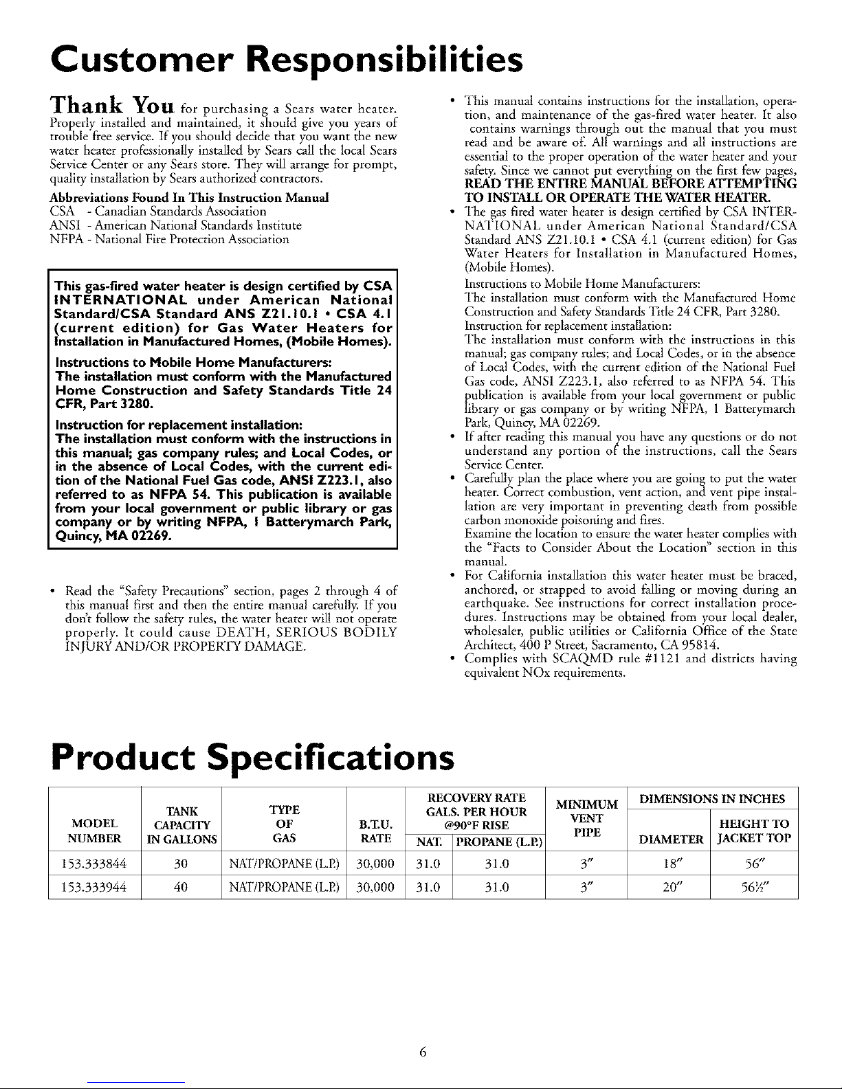
Product Specifications
MODEL
NUMBER
153.333844
153.333944
TANK
CAPACITY
IN GALLONS
30
40
TYPE
OF B.T.U.
GAS RATE
NKITPROPANE(L.E) 30,000
NKITPROPANE(L.E) 30,000
RECOVERY RATE
GALS. PER HOUR
@90°F RISE
NAT. PROPANE (LP.)
31.0 31.0
31.0 31.0
MINIMUM
VENT
PIPE
3/1
3"
DIMENSIONS IN INCHES
HEIGHT TO
DIAMETER JACKET TOP
18" 56"
20" 56/"
6

Materials and Basic Tools Needed
Materials Needed
"Ib simplify the installation Sears has available the installation
parts shown below. You may or may not need all of these materi-
als, depending on your type of installation.
WATER HEATER INSTAL-
LATION KIT WITH
FLEXIBLE CONNECTORS
FOR 3/4" OR I/2"
THREADED OR COPPER
PLUMBING
EXPANSION TANKS
FOR THERMAL
EXPANSION
CONDITIONS
AVAILABLE IN 2
GALLON AND 5
GALLON CAPACITY
THROUGH LOCAL
SEARS STORE OR
SERVICE CENTERS
FLEXIBLE WATER
HEATER GAS
CONNECTOR WITH
FITTINGS
DRAIN PANS ARE AVAILABLE IN
20", 22", 24n AND 28" DIAMETERS.
SELECT A DRAIN PAN THAT IS AT
LEAST 2n LARGER THAN THE
DIAMETER OF THE WATER HEATER
Basic Tools
You may or may not need all of these tools, depending on ycour
type of installation. These tools can be purchased at your local
Sears store.
• Pipe Wrenches (2) 14"
• Screwdriver
• Tin Snips
• 6 Foot Tape or Folding Rule
• Garden Hose
• Drill
• Pipe dope or Teflon Tape
GARDEN HOSE 6 FOOT TAPE
SLOT-HEAD SCREWDRIVER
PIPE
WRENCH
PHILLIPS SCREWDRIVER
ROLL OF TEFLON TAPE
(USE ONLY ON WATER
CONNECTIONS)
PIPE DOPE (SQUEEZE TUBE)
(USE FOR WATER AND
GAS CONNECTIONS)
TIN SNIPS
DRILL
ADDITIONAL TOOLS NEEDED
WHEN SWEAT SOLDERING
• Tubing Cutters or Hacksaw
• Propane Torch
• Soft Solder
• Solder Flux
• Emery Cloth
• Wire Brushes
HACKSAW
3/4" WIRE BRUSH
1/2_ WIRE BRUSH
ROLL OF LEAD FREE
SOFT SOLDER
PROPANE
TORCH
7
ROLL OF EMERY
CLOTH SOLDER TUBING
FLUX CUTTER
Installation Instructions
Removing the Old Water Heater
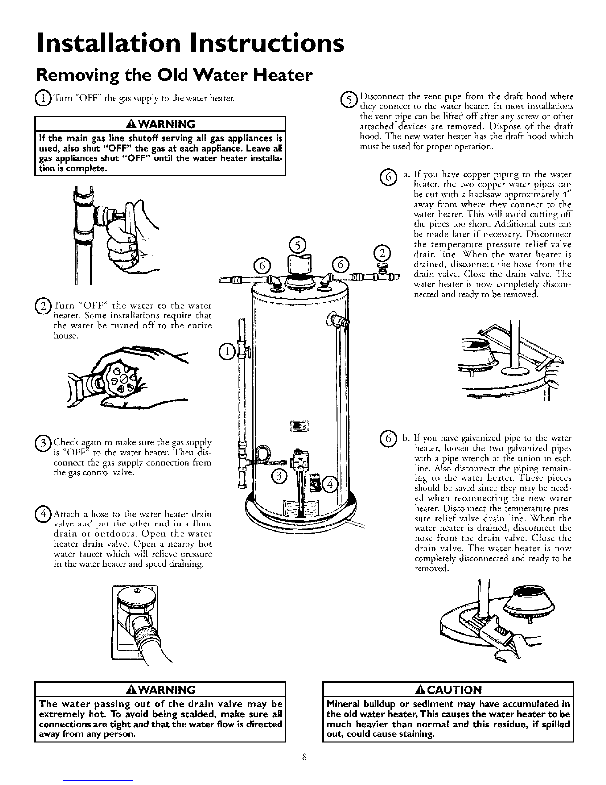
@_Ihrn "OFF" the gas supply to the water hearer.
_kWARNING
If the main gas line shutoff serving all gasappliances isI
used,alsoshut "OFF" the gasat each appliance.Leaveall
gasappliancesshut "OFF" until the water heater installa-
tion is complete.
®
@Turn "OFF" the water to the water
heater. Some installations require that
the water be turned off" to the entire
house.
Disconnect the vent pipe from the draft hood where
they connect to the water heater. In most installations
the vent pipe can be lifted off"after any screw or other
attached devices are removed. Dispose of the draft
hood. The new water heater has the draft hood which
must be used for proper operation.
a.
If you have copper piping to the water
heater, the two copper water pipes can
be cut with a hacksaw approximately 4"
away from where they connect to the
water heater. This will avoid cutting off"
the pipes too short. Additional cuts can
be made later if necessary. Disconnect
the temperature-pressure relief valve
drain line. When the water heater is
drained, disconnect the hose from the
drain valve. Close the drain valve. The
water heater is now completely discon-
nected and ready to be removed.
Check a,g,ain to make sure the gas supply
is OFF to the water heater. Then dis-
connect the gas supply connection from
the gas control valve.
Attach hose the heater drain
a to water
valve and put the other end in a floor
drain or outdoors. Open the water
heater drain valve. Open a nearby hot
water faucet which will relieve pressure
in the water heater and speed draining.
If you have galvanized pipe to the water
heater, loosen the two galvanized pipes
with a pipe wrench at the union in each
line. Also disconnect the piping remain-
ing to the water heater. These pieces
should be saved since they may be need-
ed when reconnecting the new water
heater. Disconnect the temperature-pres-
sure relief valve drain llne. When the
water heater is drained, disconnect the
hose from the drain valve. Close the
drain valve. The water heater is now
completely disconnected and ready to be
removed.
_kWARNING I
The water passing out of the drain valve may be
extremely hot. To avoid being scalded, make sure all
connections are tight and that the water flow is directed I
away from anyperson. ]
_CAUTION J
Mineral buildup or sediment may have accumulated in J
the old water heater. This causesthe water heater to be J
much heavier than normal and this residue, if spilled
out, could cause staining.
Installation Instructions (cont'd)
Facts to Consider About the
Location
Whether replacing an old water heater or putting the water
heater in a new location, the following critical points must be
observed•
This mobile home gas-flred water heater is for use in a mobile
home. You should carefully choose an indoor location for the
new water heater, because the placement is a very important
consideration for the safety of the occupants in the building and
for the most economical use of the appliance. This water heater
is for use only in mobile homes andis not intended for out-
door installation.
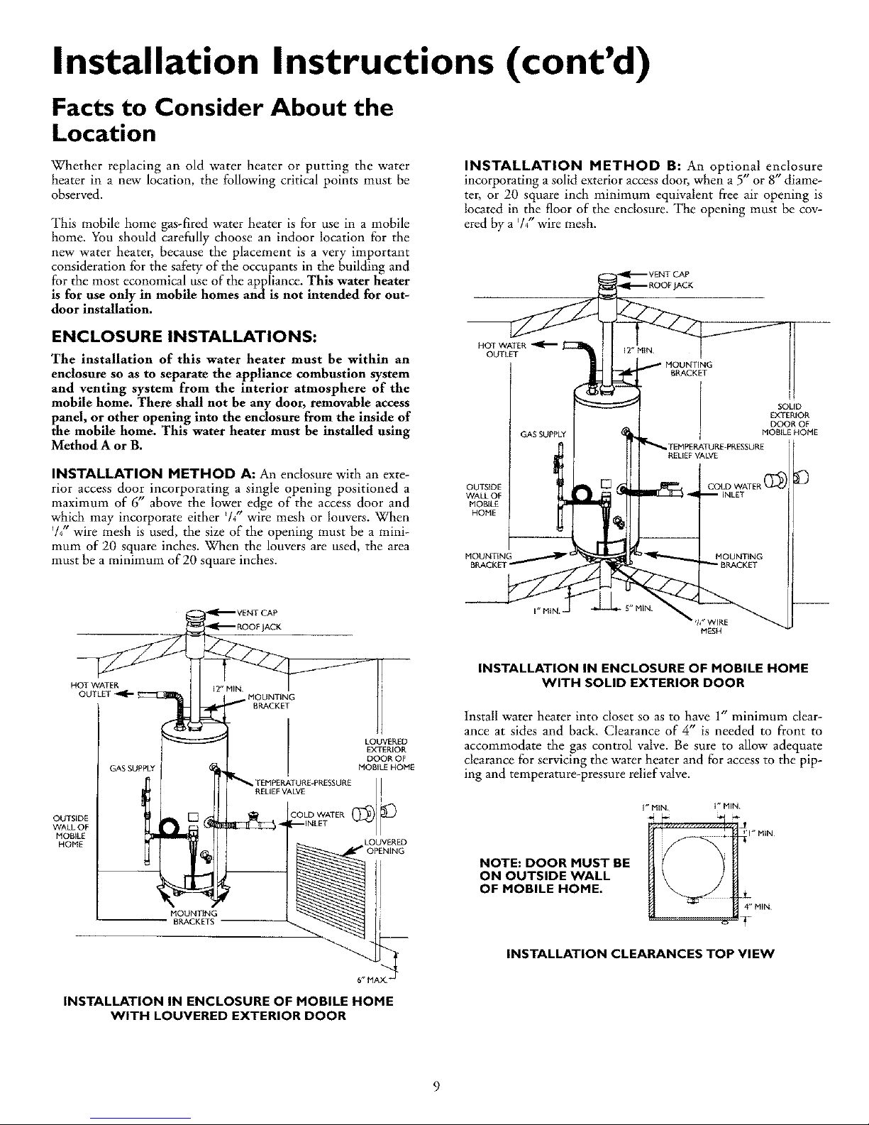
INSTALLATION METHOD B: An optional enclosure
incorporating a solid exterior access door, when a 5' or 8 diame-
ter, or 20 square inch minimum equivalent free air opening is
located in the floor of the enclosure• The opening must be cov-
ered by a 7/" wire mesh•
ENCLOSURE INSTALLATIONS:
The installation of this water heater must be within an
enclosure so as to separate the appliance combustion system
and venting system from the interior atmosphere of the
mobile home. There shall not be any door, removable access
tPhanel,or other opening into the enclosure from the inside of
e mobile home. This water heater must be installed using
Method A or B.
HOT WATER
OUTLET
I
GAS SUPPLY
SOLID
EXTERIOR
DOOR OF
MOBILE HOME
INSTALLATION METHOD A: An enclosure with an exte-
rior access door incorporating a single opening positioned a
maximum of 6" above the lower edge of the access door and
whmh may incorporate either /4 wtre mesh or louvers. When
%"wire mesh is used, the size of the opening must be a mini-
mum of 20 square inches. When the louvers are used, the area
must be a minimum of 20 square inches.
OUTSIDE
WALL OF
MOBILE
HONE
MOUNTING
BRACKET
HOT WATER
OUTLET
OUTSIDE
WALL OF
MOBILE
HOME
GAS SUPPLY
MOUNTING
BRACKETS
LOUVERED
EXTERIOR
DOOR OF
MOBILE HOME
gLqg VA%PPRessURE!
' O LEVER
LOUVERED
6" MAX
INSTALLATION IN ENCLOSURE OF MOBILE HOME
WITH LOUVERED EXTERIOR DOOR
INSTALLATION IN ENCLOSURE OF MOBILE HOME
WITH SOLID EXTERIOR DOOR
Install water heater into closet so as to have 1" minimum clear-
ance at sides and back. Clearance of 4" is needed to front to
accommodate the gas control valve• Be sure to allow adequate
clearance for servicing the water heater and for access to the pip-
ing and temperature-pressure relief valve.
NOTE: DOOR MUST BE
ON OUTSIDE WALL
OF MOBILE HOME.
I_ MIN i_MIN
_1 _ M_N_
.L
4" M_N
T
INSTALLATION CLEARANCES TOP VIEW
9
Installation Instructions (cont'd)
Facts to Consider About the
Location (cont'd)
_WARNING
Minimum clearances between the water heater and com-
bustible and noncombustible construction are Iu at the
sides and rear, 4n at the front, and 6" from the vent pipe.
Clearance from the top of the jacket is 12" on most mod-
els. Note that a lesser dimension may be allowed on some
models. Refer to the label on the water heater adjacent to
the gas control valve for all clearances.
The water heater should be secured to the floor and to the wall
of the enclosure with the mounting brackets provided. For
bracket location refer to "Securing Water Heater to Floor and
Wall" in the "Installation Instructions" section.
When a mobile home is skirted, an air intake opening with a
minimum free area of 32 square inches must be provided in the
skirt. If the opening is covered by louvers or screen, the total free
area must be 32 square inches. Other gas fired appliances in the
home will require additional free air openings; consult these
manufacturers for correct sizing.
AWARNING
A gaswater heatercannotoperateproperlywithoutthe cor-
rectamount ofair for combustion.Do not installin a confined
areasuchacloset,unlessyouprovideair asshowninthe"Facts
to ConsiderAbout the Location"sectionon page9. Never
obstructthe flowof ventilationair If you haveanydoubtsor
questionsatall,callyourgascompanyor SearsServiceCenter
Failureto providethe properamount of combustionair can
result in a fire or explosionandcancauseDEATH, SERIOUS
BODILYINJUR_,OR PROPERTYDAMAGE.
AWARNING
When the system requires water at temperatures higher than
required for other uses,the hot water system may require a
means such as a mixing valve to be installed to temper the
water at certain points of use. Some people are more likelyto
be permanently injured by hot water than others; these include
the elderly, children, the infirm, or the physically/mentallyhand-
icapped.Before immersing yourselfor anyone else in hot water,
be sure to check the water temperature. WARNING: HOT-
TER WATER INCREASES THE RISK OF SCALD INJURY.
(Also see "Temperature Regulation" section) Mixing valvesare
available at plumbing supplyor hardware stores. Follow manu-
facturers instructionsfor installationofthese valves.
AWARNING
Thiswater heater shallnot be connectedto anyheatingsys-
temsor componem(s)previouslyusedwitha nonpotablewater
heatingappliance.
_WARNING
If this water beater will be used in beaut7 shops,barber shops,
cleaning establishments, or self-service laundries with dry
cleaning equipment, it is imperative that the water beater or
water beaters be installed so that combustion and ventilation
air be taken from outside these areas. Refer to the '*Facts to
Consider About the Location" section of this manual and also
the current edition of the National Fuel Gas Code, ANSI
Z223.1, also referred to as NFPA 54 for specificsprovided con-
cerning air required.
_,WARNING J
Toxicchemicalssuchas usedfor treatment of boilersor non-J
potablewater heatingappliancesshallneverbe introducedinto
a potablewater heatingsystem.
ACAUTION
WATER HEATERS EVENTUALLY LEAK: Installation of the
water heater must be accomplished in sucha manner that if
the tank or any connectionsshouldleak, the flow of water will
not causedamage to the structure. When such locations can-
not be avoided, a suitable drain pan should be installed under
the water heater. Drain pans are available at your local Sears
store. Such a drain pan must be not greater than I '/zinches
deep, have a minimum length and width of at least 2 inches
greater than the water heater dimensions and must be piped
to an adequate drain. The pan must not restrict combustion air
flow.
10
When a drain pan is required, the installation must conform to
"Method A" on page 9.
AWARNING
INSTALLATIONS IN AREAS WHERE FLAMMABLE LIQUIDS
(VAPORS) ARE LIKELY TO BE PRESENT OR STORED
(GARAGES, STORAGE, AND UTILITY AREAS, ETC):
Flammable liquids(such as gasoline,solvents, propane (LP) or
butane, etc.), all of which emit flammable vapors, may be
improperly stored or used in suchareas. The gaswater heater
pilot light or main burner can ignite suchvapors. The resulting
flashbackand fire can causedeath or seriousburns to anyone m
the area,as well asproperty damage.
If installation in suchareas isyour only option, then the installa-
tion must be accomplished in a way that the pilot flame and
main burner flame are elevated from the floor at least 18inches.
While this may reduce the changesof flammable vapors from a
floor spillbeing ignited,gasolineand other flammable substances
should never be stored or used in the same room or area con-
taining a gaswater heater or other open flame or spark produc-
ingappliance.
NOTE: Flammable vapors may be drawn by air currents from
other areas ofthe structure to the appliance.
AWARNING
Propellantsof aerosolspraysandvolatilecompounds,(clean-
ers,chlorinebasedchemicals,refrigerants,etc.) in additionto
beinghighlyflammableinmanycases,willalsochangeto cor-
rosive hydrochloricacid when exposedto the combustion
productsof the water heater.The results canbe hazardous
and alsocauseproductfailure.
_,WARNING
Thiswater heatermust not be installeddirectlyon carpeting.
Carpeting must be protected by a metal or wood panel
beneaththe applianceextending beyondthe full width and
depth of the appliance byat least 3 inches(76.2mm) in an)
direction,or if the applianceisinstalledinanalcoveorcloset
the entire floormust be coveredbythe panel.Failureto heec
thiswarningmayresult inafirehazard.
 Loading...