

Kenmore THE ECONOMIZER 153.332070, 153.332060, 153.332050, 153.332040, ECONOMIZER 6 Owner's Manual
Owner's Manual
THE ECONOM ERTM 6
GAS WATER HEATER
POWER VENTED GAS MODELS
WITH HOT SURFACE IGNITION
FOR POTABLE WATER HEATING ONLY.
NOT SUITABLE FOR SPACE HEATING.
NOT FOR USE IN MOBILE HOMES.
MODEL NO.
153.332040 40 Gallon Nat
153.332050 50 Gallon Nat
153.332060 40 Gallon LP
153.332070 50 Gallon LP
C3 Technology _*Gas Water Heaters meet
the newANSI Z21.10.1 standard that deals
with the accidental or unintended ignition
of flammable vapors, such as those
emitted by gasoline,
Read and understand instruction
manual and safety messages
before installing, operating or
servicing thiswater heater
Failure to follow instructions and
safety messages could result in
death or serious injury.
instruction manual must remain with
water beater.
, Safety hstructions
mnstaHation
GA$-FmHEg
Operation
, Care and Maintenance
* Troubleshooting
, Parts List
For Your Safety
AN ODORANT ISADDED TO THE GAS USED BY THIS WATER HEATER.
WARNING: If the information in these
instructions is not followed exactly, a fire
or explosion may result causing property
damage, personal injury or death.
--Do not store or use gasoline or other
flammable vapors and liquids in the
vicinity of this or any other appliance.
-- WHAT TO DO IF YOU SMELL GAS:
• Do not try to Hght any appliance.
o Do not touch any emectricam switch; do
not use any phone in your buimding.
• mmmediatemy caml your gas suppmier
from a neighbor's phone. Fommow the
gas eupplier'e instructions,
Si no puede leer o entender el ingles y necesita el manual instructivo
y/o etiquetas en espa5oJ puede obtenerlos Ilamando al
1o800o821o2017. NO TRATE DE INSTALAR O OPERAR ESTE
CALENTADOR DEAGUAsi no entiende la infom_aci6n en las etiquetas
o en el manual instructivo. No hacer caso de esta advertencia podria
resultar en la MU ERTE O GRAVES LESIONES CORPORALES.
Sears, Roebuck and Co., Hoffman Estates, _L 60179 U.S.A
PRINTED IN THE U.S.A. 0905 www.sears.com PART NO. 185249-000
o mfyou cannot reach your gas suppmier,
cammthe fire department.
--Installation and service must be
performed by a qualified installer,
service agency orthe gas supplier.
Yoursafetyandthesafetyofothersisextremely important in the installation, use and servicLng of tMs water heater.
Many safetyore[ated messages and instructLons have been provided in this manual and on your own water heater to warn you and
others of a potential injury hazard. Read and obey all safety messages and instructions throughout tMs manuaL, mtis very
important that the meaning of each safety message is understood by you and others who instam[, use or service this water heater.
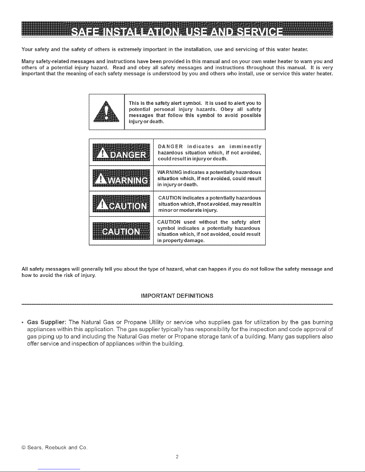
This is the safety amert symbol [t is used to alert you to
potential persona[ injury hazards. Obey a[[ safety
messages that fommow this symbom to avoid possibme
injuryor death.
DANGER indicates an imminently
m!!l[[I
_m!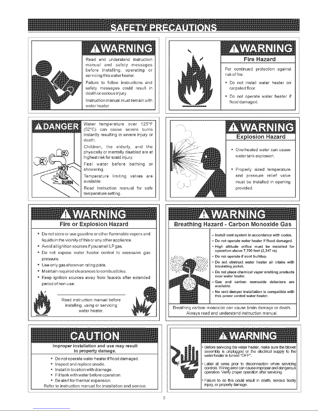
Readandunderstandinstruction
manualandsafetymessages
beforeinstalling,operatingor
servicingthiswaterheater.
Failuretofollowinstructionsand
safetymessagescouldresultin
deathorseriousinjury,
Instructionmanualmustremainwith
waterheater.
Water temperature over 125°F
(52°0) can cause severe burns
instantly resulting in severe injury or
death.
Children, the elderly, and the
physically or mentally disabled are at
highest risk for scald injury.
Feel water before bathing or
showering.
Temperature limiting valves are
available.
Read instruction manual for safe
temperature setting.
Fire Hazard
For continued protection against
riskoffire:
" Do not install water heater on
carpeted floor.
_' Do not operate water heater if
flood damaged.
/,- -,,
)Iosion Hazard
Overheated water can cause
watertank explosion.
,, Propedy sized temperature
and pressure relief valve
must be inatalled in opening
provided.
Fire or Explosion Hazard
Do not store or use gasoline or other flammable vapors and
liquids in the vicinity of this or any other appliance.
,, Avoid all ignition sources if you smell LP gas
'_ Do not expose water heater control to excessive gas
pressure,
Use onlygasshown on rating plate.
" Maintain required clearances to combustibbs.
Keep ignition sources away from faucets after extended
period of nomuse.
/
Read instruction manual before
installing, using or servicing
water heater.
improper ies_llation and use may result
in property damage.
Do not operate water heater ftftood damaged.
Inspect and replace anode.
Install in location with drainage,
Fill tank with water before operation,
Be alert for thermal expansion.
Refer to instruction manual for installation and seance.
Breathing Hazard - Carbon iVionoxide Gas
• Install vent system in accordance with codes.
• Do not operate wafer heater if flood damaged,
• High altitude orifice must be installed for
operation above 7,700 feet (2,347 rn).
- Do not operate if soot buildup.
. _S,.,=% *
Breathing carbon monoxide can cause brain damage or death
Always read and understand instruction manual.
, Do not obstruct water heater air intake with
insulating jacket,
, Do not place chemical vapor emitting products
near wafer heater.
• Gas and carbon monoxide detectors are
available.
• No vent damper insfellation is csmpagble with
this power vented water heater.
, Betore servicing the water heater,make sure the bio_e_
assembly is unplugged or the electrical supply to the
wafer heater is turned "OFF".
operation Ver_y properopera,on after servicing
' Failure to do this could resu_ in death, serious bodi_]
injury,or property damage.
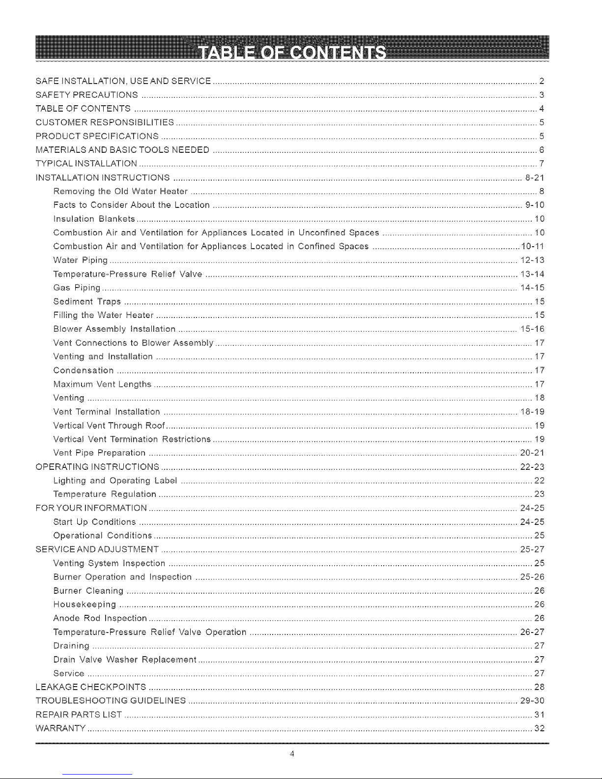
SAFEINSTALLATION,USEANDSERVICE....................................................................................................................................2
SAFETYPRECAUTIONS.................................................................................................................................................................3
TABLEOFCONTENTS....................................................................................................................................................................4
CUSTOMERRESPONSIBILITIES...................................................................................................................................................5
PRODUCTSPECIFICATIONS.........................................................................................................................................................5
MATERIALSANDBASICTOOLSNEEDED....................................................................................................................................6
TYPICALINSTALLATION..................................................................................................................................................................7
INSTALLATIONINSTRUCTIONS..............................................................................................................................................8=21
RemovingtheOldWaterHeater.............................................................................................................................................8
FactstoConsiderAbouttheLocation..............................................................................................................................9=10
InsulationBlankets.................................................................................................................................................................10
CombustionAirandVentilationforAppliancesLocatedin UnconfinedSpaces.............................................................10
CombustionAirandVentilationforAppliancesLocatedinConfinedSpaces............................................................10=11
WaterPiping......................................................................................................................................................................12-13
Temperature=PressureReliefValve...............................................................................................................................13-14
GasPiping.........................................................................................................................................................................14-15
SedimentTraps......................................................................................................................................................................15
FillingtheWaterHeater.........................................................................................................................................................15
BlowerAssemblyInstallation..........................................................................................................................................15-16
VentConnectionstoBlowerAssembly.................................................................................................................................17
VentingandInstallation.........................................................................................................................................................17
Condensation.........................................................................................................................................................................17
MaximumVentLengths..........................................................................................................................................................17
Venting.....................................................................................................................................................................................18
VentTerminalInstallation................................................................................................................................................18-19
VerticalVentThroughRoof.....................................................................................................................................................19
VerticalVentTerminationRestrictions..................................................................................................................................19
VentPipePreparation......................................................................................................................................................20-21
OPERATINGINSTRUCTIONS.................................................................................................................................................22-23
LightingandOperatingLabel.................................................................................................................................................
TemperatureRegulation........................................................................................................................................................23
FORYOURINFORMATION......................................................................................................................................................24-25
StartUpConditions..........................................................................................................................................................24-25
OperationalConditions..........................................................................................................................................................25
SERVICEANDADJUSTMENT.................................................................................................................................................25-27
VentingSystemInspection....................................................................................................................................................25
BurnerOperationandInspection...................................................................................................................................25-26
BurnerCleaning.....................................................................................................................................................................26
Housekeeping........................................................................................................................................................................26
AnodeRodInspection............................................................................................................................................................26
Temperature-PressureReliefValveOperation.............................................................................................................26-27
Draining...................................................................................................................................................................................27
DrainValveWasherReplacement........................................................................................................................................27
Service.....................................................................................................................................................................................27
LEAKAGECHECKPOINTS............................................................................................................................................................28
TROUBLESHOOTINGGUIDELINES......................................................................................................................................29-30
REPAIRPARTSLIST......................................................................................................................................................................31
WARRANTY.....................................................................................................................................................................................32
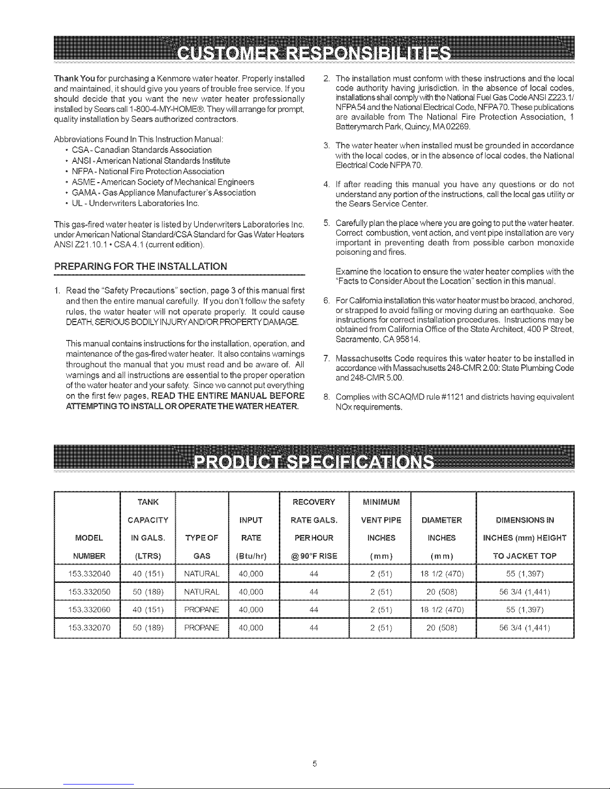
ThankYouforpurchasingaKenmorewaterheater.Properlyinstalled
andmaintained,itshouldgiveyouyearsoftroublefreeservice,ifyou
shoulddecidethatyouwantthenewwaterheaterprofessionally
installedbySearscall1-8004-M%HOME®.They\,viiiarrangeforprompt,
qualityinstallationbySearsauthorizedcontractors.
AbbreviationsFoundInThisInstructionManual:
CSA-CanadianStandardsAssociation
ANSI-American National Standards institute
NFPA- National Fire Protection Association
ASME - American Society of Mechanical Engineers
GAMA - Gas Appliance Manufacturer's Association
UL - Underwriters Laboratories Inc.
The installation must conform with these instructions and the Ioca!
code authority having iurisdiction. In the absence of local codes,
installations shall comply with the National Fuel Gas COdeANSI Z223.1/
NFPA54 and the National Electrical Code, NFPA70. These publications
are available from The National Fire Protection Association, 1
Battery,march Park, Quincy, MA 02269.
3. The water heater when installed must be grounded in accordance
with the local codes, or in the absence of local codes, the National
Electrical Code NFPA 70.
4. If after reading this manual you have any questions or do not
understand any portion of the instructions, call the local gas utility or
the Sears Service Center.
This gas-fired water heater is listed by Underwriters Laboratories Inc.
underAmerican National Standard/CSA Standard for Gas Water Heaters
ANSI Z21.10.1 • CSA4.! (current edition).
PREPARING FOR THE INSTALLATION
Read the "Safety Precautions" section, page 3 of this manual first
and then the entire manual carefully. If you don't follow the safety
rules, the water heater will not operate properly. It could cause
DEATH, SERIOUS BODILY INJURYAND/OR PROPERTY DAMAGE.
This manual contains instructions for the installation, operation, and
maintenance of the gas4ired water heater. Italso contains warnings
throughout the manual that you must read and be aware of. All
warnings and all instructions are essential to the proper operation
of the water heater and your safety. Since we cannot put eveQ/thing
on the first few pages, READ THE ENTIRE MANUAL BEFORE
ATTEMPTING TO INSTALL OR OPERATE THE WATER HEATER.
TANK
RECOVERY
Carefully plan the place where you are going to put the water heater.
Correct combustion, vent action, and vent pipe installation are very
important in preventing death from possible carbon monoxide
poisoning and fires.
Examine the location to ensure the water heater complies with the
"Facts to ConsiderAbout the Location" section in this manual.
For California installation this water heater must be braced, anchored,
or strapped to avoid falling or moving during an earthquake. See
instructions for correct installation procedures. Instructions may be
obtained from California Office of the State Architect, 400 P Street,
Sacramento, CA 95814.
7. Massachusetts Code requires this water heater to be installed in
accordance with Massachusetts 248-CMR 2.00: State Plumbing Code
and 248-CMR 5.00.
8. CompiieswithSCAQMDrule#1121 and distdcts having equivalent
NOx requirements.
MINIMUM
CAPACITY
MODEL
NUMBER
153.332040
153.332050
153.332060
153.332070
IN GALS.
(LTRS)
40 (151)
50 (169)
40 (151)
50 (16e)
TYPE OF
GAS
NATURAL
NATURAL
PROPANE
PROPANE
INPUT
RATE
(Btuthr)
40,000
40,000
40,000
40,000
RATE GALS.
PERHOUR
@90°F R_SE
44
44
44
44
VENT PRPE
INCHES
(ram)
2 (51)
2 (51)
2 (51)
2 (51)
DBA_,_ETER
iNCHES
(ram)
18 1/2 (470)
20 (508)
18 1/2 (470)
20 (508)
DIMENSBONS IN
iNCHES (ram} NERGHT
TO JACKET TOP
55 (1,397)
56 3/4 (1,441)
55 (1,397)
56 3/4 (1,441)
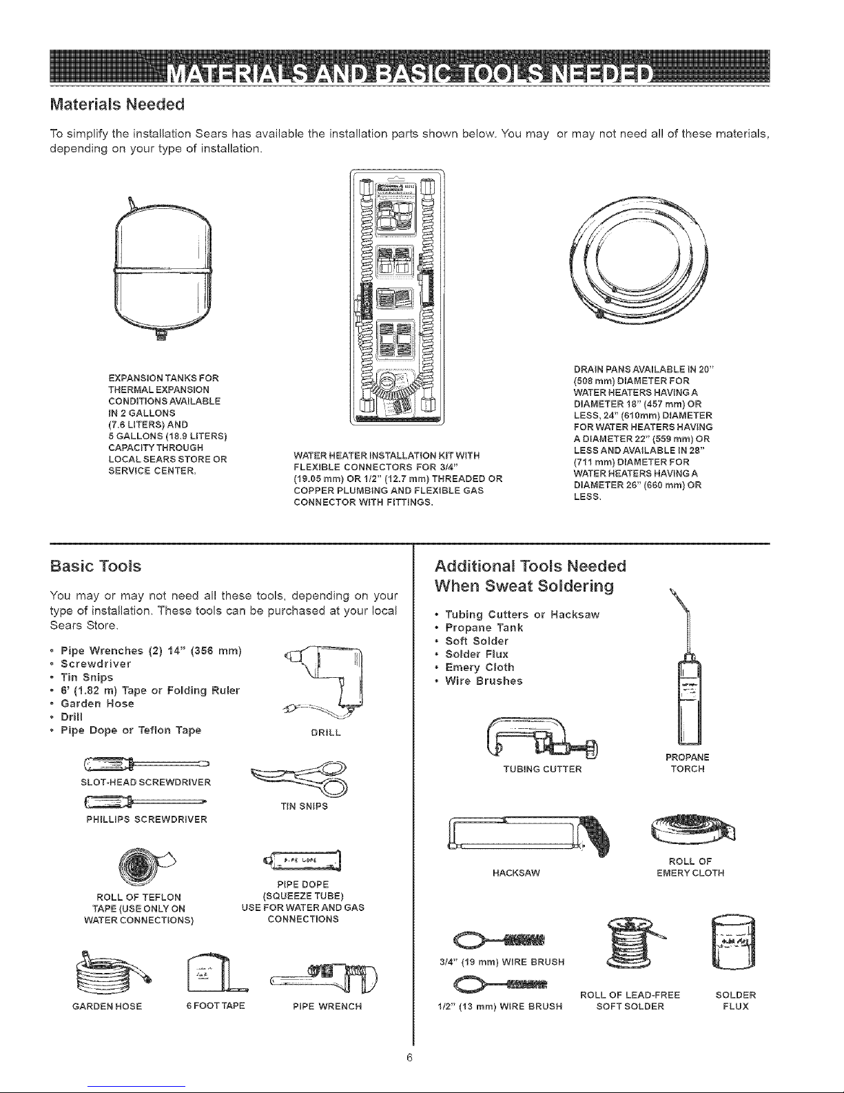
Materials Needed
To simplify the installation Sears has available the installation parts shown below. You may or may not need al! of these materials,
depending on your type of installation.
_'_"'111'I
_,_1
_'_11_
EXPANSION TANKS FOR
THERMAL EXPANSION
CONDITIONS AVAILABLE
iN 2 GALLONS
(7.8 LITERS} AND
5 GALLONS (18.9 LITERS)
CAPACITY THROUGH
LOCAL SEARS STORE OR
SERVICE CENTER.
WATER HEATER INSTALLATION KIT WITH
FLEXIBLE CONNECTORS FOR 8/4"
(19.05 ram} OR 1/2" (12.7 ram) THREADED OR
COPPER PLUMBING AND FLEXIBLE GAS
CONNECTOR WITH FITTINGS.
DRA_N PANS AVAILABLE iN 20"
(508 ram} DIAMETER FOR
WATER HEATERS HAVING A
DIAMETER 18" (457 ram) OR
LESS, 24" (810ram) DIAMETER
FOR WATER HEATERS HAVING
A DIAMETER 22" (559 ram) OR
LESS AND AVAILABLE IN 28"
(711 rnm} DIAMETER FOR
WATER HEATERS HAVING A
DIAMETER 28" (650 ram) OR
LESS.
Basic Too_s
You may or may not need all these tools, depending on your
type of installation. These tools can be purchased at your local
Sears Store.
Pipe Wrenches (2) 14" (356 ram)
Screwdriver
Tin Snips
8' (1.82 m) Tape or Fo_ding Ruler
Garden Hose
DriH
Pipe Dope or Teflon Tape DRILL
SLOT-HEAD SCREWDRIVER
PHILLIPS SCREWDRIVER
ROLL OF TEFLON
TAPE (USE ONLY ON
WATER CONNECTIONS)
TiN SNIPS
P{PE DOPE
(SQUEEZE TUBE)
USE FOR WATER AND GAS
CONNECTIONS
Additional Tools Needed
When Sweat Soldering
Tubing Cutters or Hacksaw
Propane Tank
Soft Solder
Solder F_ux
Emery C_oth
Wire Brushes
TUBING CUTTER
HACKSAW
8/4" (19 ram) WiRE BRUSH
PROPANE
TORCH
ROLL OF
EMERYCLOTH
GARDEN HOSE
8 FOOT TAPE
PIPE WRENCH
1/2" (13 ram) WiRE BRUSH
ROLL OF LEAD-FREE
SOFTSOLDER
SOLDER
FLUX
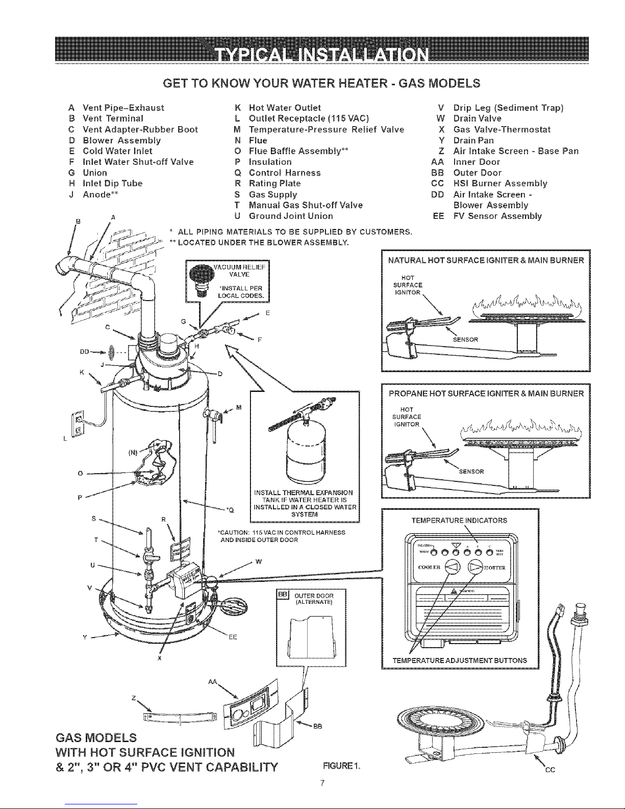
GET TO KNOW YOUR WATER HEATER - GAS MODELS
A Vent Pipe=Exhaust
B Vent Terminal
C Vent Adapter-Rubber Boot
D Blower Assembly
E CoJd Water Inlet
F runlet Water Shut-off Valve
G Union
H runlet Dip Tube
J Anode**
* ALL P}P}NG MATERIALS TO BE SUPPLIED BY CUSTOMERS.
** LOCATED UNDER THE BLOWER ASSEMBLY.
K Hot Water Outlet
L Outlet Receptacle (115 VAC)
M Temperature-Pressure Relief Valve
N Flue
O Hue Baffte Assembly**
P mnsulation
Q Control Harness
R Rating Plate
S Gas Suppmy
T Manua{ Gas Shut-off Valve
U Ground Joint Union
*INSTALL PER
LOCAL CODES.
V Drip Leg (Sediment Trap)
W DrainValve
X Gas Valve-Thermostat
Y Drain Pan
Z Air mntake Screen o Base Pan
AA runner Door
BB Outer Door
CC HSl Burner Assembly
DD Air intake Screen o
Blower Assembly
EE FV Sensor Assembly
NATURAL HOT SURFACE IGNITER & MABNBURNER
NOT
SURFACE
PROPANE HOT SURFACE IGNITER & MAIN BURNER
NOT
EURFACE
INSTALL THERMAL EXPANSUON
UNSTALLED IN A CLOSED WATER
*CAUTION: 115 VAC IN CONTROL HARNESS
AND INSIDE OUTL=R DOOR
EE
GAS MODELS
WiTH HOT SURFACE _GN_T_ON
& 2", 3°' OR 4" PVC VENT CAPAB_UTY
TANK UFWATER HEATER iS
SYSTEM
OUTER DOOR
(ALTERNATE)
FIGURE1,
7
TEMPERATURE INDICATORS
J
i
CC
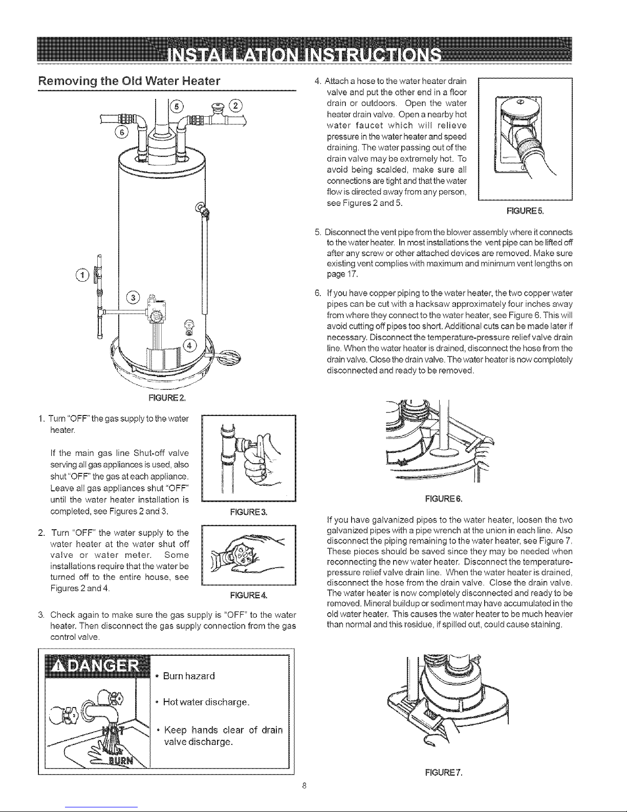
Removing the Old Water Heater
®
4. Attach a hose to the water heater drain
valve and put the other end in a floor
drain or outdoors. Open the water
heater drain valve. Open a nearby hot
water faucet which will relieve
pressure in the water heater and speed
draining. The water passing out of the
drain valve may be extremely hot. To
avoid being scalded, make sure all
connections are tight and that the water
flow is directed away from any person,
see Figures 2 and 5.
Disconnect the vent pipe from the blower assembly where it connects
to the water heater. In most installations the vent pipe can be lifted off
after any screw or other attached devices are removed. Make sure
existing vent complies with maximum and minimum vent lengths on
page 17.
If you have copper piping to the water heater, the two copper water
pipes can be cut with a hacksaw approximately four inches away
from where they connect to the water heater, see Figure 6. This will
avoid cutting off pipes too short. Additional cuts can be made later if
necessary. Disconnect the temperature-pressure relief valve drain
line. When the water heater is drained, disconnect the hose from the
drain valve. Close the drain valve. The water heater is now completely
disconnected and ready to be removed.
FmGURE5.
FIGURE2.
1. Turn "OFF" the gas supply to the water
heater.
If the main gas line Shut-off valve
serving all gas appliances is used, also
shut "OFF" the gas at each appliance.
Leave all gas appliances shut "OFF"
until the water heater installation is
completed, see Figures 2 and 3.
2. Turn "OFF" the water supply to the
water heater at the water shut off
valve or water meter. Some
installations require that the water be
turned off to the entire house, see
Figures 2 and 4.
3. Check again to make sure the gas supply is "OFF" to the water
heater. Then disconnect the gas supply connection from the gas
control valve.
I
F_GURE3.
RGURE4.
Burn hazard
RGURE 6.
If you have galvanized pipes to the water heater, loosen the two
galvanized pipes with a pipe wrench at the union in each line. Also
disconnect the piping remaining to the water heater, see Figure 7.
These pieces should be saved since they may be needed when
reconnecting the new water heater. Disconnect the temperature°
pressure relief valve drain line. When the water heater is drained,
disconnect the hose from the drain valve. Close the drain valve.
The water heater is now completely disconnected and ready to be
removed. Mineral buildup or sediment may have accumulated in the
old water heater. This causes the water heater to be much heavier
than normal and this residue, if spilled out, could cause staining.
, Hot water discharge.
• Keep hands clear of drain
RGURE 7.
FACTS TO CONSIDER ABOUT THE LOCATION
Carefully choose an indoor location for the new water heater, because
the placement is a very important consideration for the safety of the
occupants in the building and for the most economical use of the appliance.
This water heater is not for use in manufactured (mobile) homes
or outdoor installation.
Whether replacing an old water heater or putting the water heater in a
new location, the following critical points must be observed:
1. Select a location indoors as close as practical to the vent terminal or
location to which the water heater vent piping is going to be connected,
and as centralized with the water piping system as possible.
2. Selected location must provide adequate clearances for servicing
and proper operation of the water heater.
Property Damage Hazard
All water heaters eventually leak.
, Do not install without adequate drainage.
Installation of the water heater must be accomplished in such a manner
that if the tank or any connections should leak, the flow will not cause
damage to the structure. For this reason, itis not advisable to install the
water heater in an attic or upper floor. When such locations cannot be
avoided, a suitable drain pan should be installed under the water heater.
Drain pans are available at your local hardware store. Such a drain pan
must have a minimum length and width of at least 2" (5.1 cm) greater than
the water heater dimensions and must be piped to an adequate drain.
The pan must not restrict combustion air flow.
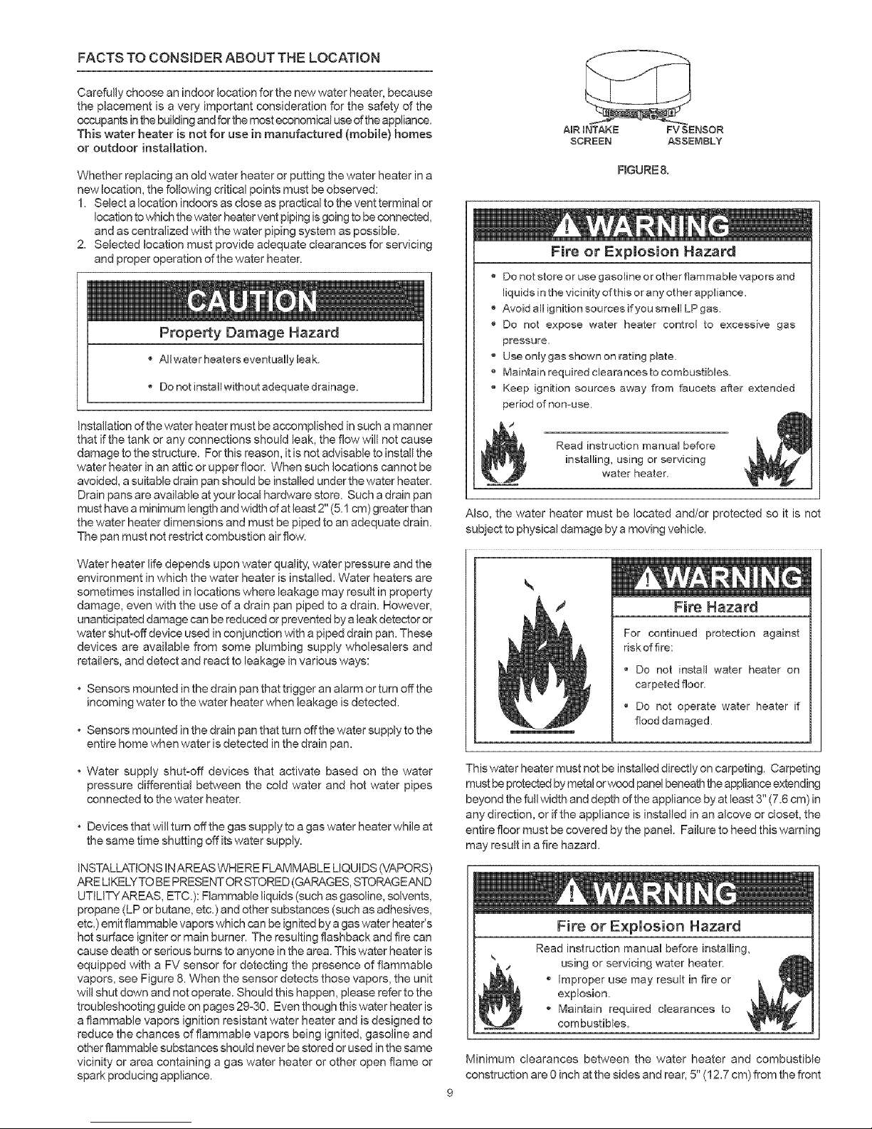
AIR BNTAKE
SCREEN
FIGURE&
FVSENSOR
ASSEIVnIBLY
Fire or Explosion Hazard
Do not store or use gasoline or other flammable vapors and
liquids in the vicinity of this or any other appliance.
Avoid all ignition sources if you smell LP gas.
Do not expose water heater control to excessive gas
pressure.
_' Use only gas shown on rating plate
Maintain required cleara nces to combustibles
'_ Keep ignition sources away from faucets after extended
period of nomuse.
/
Read instruction manual before
installing, using or servicing
water heater.
Also, the water heater must be located and/or protected so it is not
subiect to physical damage by a moving vehicle.
Water heater life depends upon water quality, water pressure and the
environment in which the water heater is installed. Water heaters are
sometimes installed in locations where leakage may resuJt in property
damage, even with the use of a drain pan piped to a drain. However,
unanticipated damage can be reduced or prevented by a leak detector or
water shut-off device used in conjunction with a piped drain pan. These
devices are available from some plumbing supply wholesalers and
retailers, and detect and react to leakage in various ways:
• Sensors mounted in the drain pan that trigger an alarm or turn offthe
incoming water to the water heater when leakage is detected.
• Sensors mounted in the drain pan that turn offthe water supply to the
entire home when water isdetected in the drain pan.
* Water supply shut-off devices that activate based on the water
pressure differential between the cold water and hot water pipes
connected to the water heater.
• Devices that will turn off the gas supply to a gas water heater while at
the same time shutting off its water supply.
INSTALLATIONS INAREAS WHERE FLAMMABLE LIQUIDS (VAPORS)
ARE LIKELYTO BE PRESENT OR STORED (GARAGES, STORAGEAND
UTtLITYAREAS, ETC.): Flammable liquids (such as gasoline, solvents,
propane (LP or butane, etc.) and other substances (such as adhesives,
etc.) emit flammable vapors which can be ignited by a gas water heater's
hot surface igniter or main burner. The resulting flashback and fire can
cause death or serious burns to anyone in the area. This water heater is
equipped with a FV sensor for detecting the presence of flammable
vapors, see Figure 8. When the sensor detects those vapors, the unit
will shut down and not operate. Should this happen, please refer to the
troubleshooting guide on pages 29°30. Even though this water heater is
a flammable vapors ignition resistant water heater and is designed to
reduce the chances of flammable vapors being ignited, gasoline and
other flammable substances should never be stored or used in the same
vicinity or area containing a gas water heater or other open flame or
spark producing appliance.
Fire Hazard
For continued protection against
riskoffire:
Do not install water heater on
carpeted floor.
Do not operate water heater if
flood damaged.
This water heater must not be installed directly on carpeting. Carpeting
must be protected by metal or wood panel beneath the appliance extending
beyond the full width and depth of the appliance by at least 3" (7.6 cm) in
any direction, or ifthe appliance is installed in an alcove or closet, the
entire floor must be covered by the panel. Failure to heed this warning
may result in a fire hazard.
Fire or Explosion Hazard
Read instruction manual before [nstaNing,
using or servicing water heater
Improper use may result in fire or
explosion.
Maintain required clearances to
combustibles.
Minimum clearances between the water heater and combustible
construction are 0 inch at the sides and rear, 5" (12.7 cm) from the front
9
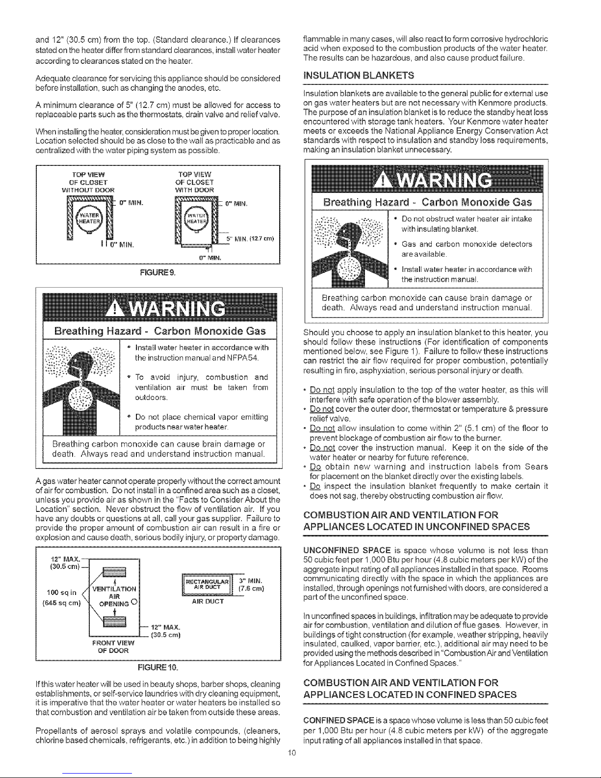
and12"(30.5cm)fromthetop.(Standardclearance.)Ifclearances
statedontheheaterdifferfromstandardclearances,instalwaterheater
accordingtoclearancesstatedontheheater.
Adequateclearanceforservicingthisapplianceshouldbeconsidered
beforeinstallation,suchaschangingtheanodes,etc.
Aminimumclearanceof5"(!2.7cm)mustbea/owedforaccessto
replaceablepartssuchasthethermostats,drainvalveandreliefvalve.
Wheninstallingtheheater,considerationmustbegiventoproperlocation.
Locationselectedshouldbeasclosetothewa/aspracticableandas
centralizedwiththewaterpipingsystemaspossible.
I I 0" IIIN.
FIGURE!.
flammableinmanycases,will also react to form corrosive hydrochloric
acid when exposed to the combustion products of the water heater.
The results can be hazardous, and also cause product failure.
INSULATION BLANKETS
Insulation blankets are available to the general public for external use
on gas water heaters but are not necessary with Kenmore products.
The purpose of an insulation blanket is to reduce the standby heat loss
encountered with storage tank heaters. Your Kenmore water heater
meets or exceeds the National Appliance Energy Conservation Act
standards with respect to insulation and standby loss requirements,
making an insulation blanket unnecessary.
Breathing Hazard - Carbon Monoxide Gas
Do not obstruct water heater air intake
with insulating blanket.
Gas and carbon monoxide detectors
are avalable.
Instal water heater in accordance with
the instruction manual.
Breathing carbon monoxide can cause brain damage or
death. Always read and understand instruction manual.
Breathing Hazard - Carbon Monoxide Gas
Install water heater in accordance with
the instruction manual and NFPA54.
To avoid injury, combustion and
_.,,_ _ ventilation air must be taken from
outdoor°
• Do not place chemical vapor emitting
products near water heater
Breathing carbon monoxide can cause brain damage or
death. Always read and understand instruction manual.
A gas water heater cannot operate properly without the correct amount
of air for combustion. Do not install in a confined area such as a closet,
unless you provide air as shown in the "Facts to Consider About the
Location" section. Never obstruct the flow of ventilation air. If you
have any doubts or questions at all, call your gas supplier. Failure to
provide the proper amount of combustion air can result in a fire or
explosion and cause death, serious bodily injury, or property damage.
t2" MAX.--
(80,5cm} --
VI_NTILATION
AIR DUCT
-- 12" MAX.
FRONT VIEW
OF DOOR
If this water heater will be used in beauty shops, barber shops, cleaning
establishments, or self-service laundries with dry cleaning equipment,
it is imperative that the water heater or water heaters be installed so
that combustion and ventilation air be taken from outside these areas.
Prope/ants of aerosol sprays and volatile compounds, (cleaners,
chlorine based chemicals, refrigerants, etc.) in addition to being highly
(30.5era)
FIGURE 10.
Should you choose to apply an insulation blanket to this heater, you
should follow these instructions (For identification of components
mentioned below, see Figure 1). Fa/ure to fo/ow these instructions
can restrict the air flow required for proper combustion, potentially
resulting in fire, asphyxiation, serious personal injury or death.
Do not apply insulation to the top of the water heater, as this will
interfere with safe operation of the blower assembly.
Do not cover the outer door, thermostat or temperature & pressure
relief valve.
Do not a/ow insulation to come within 2" (5.1 cm) of the floor to
prevent blockage of combustion air flow to the burner.
Do not cover the instruction manual. Keep it on the side of the
water heater or nearby for future reference.
D__.£obtain new warning and instruction labels from Sears
for placement on the blanket directly over the existing labels.
D__£inspect the insulation blanket frequently to make certain it
does not sag, thereby obstructing combustion air flow.
COMBUSTION AIR AND VENTILAT_ON FOR
APPLIANCES LOCATED IN UNCONFINED SPACES
UNCONFINED SPACE is space whose volume is not less than
50 cubic feet per 1,000 Btu per hour (4.8 cubic meters per kW) of the
aggregate input rating of a/appliances installed in that space. Rooms
communicating directly with the space in which the appliances are
insta/ed, through openings not furnished with doors, are considered a
part of the unconfined space.
In unconfined spaces in buildings, infiltration may be adequate to provide
air for combustion, ventilation and dilution of flue gases. However, in
buildings of tight construction (for example, weather stripping, heavily
insulated, caulked, vapor barrier, etc.), additional air may need to be
provided using the methods described in "Combustion Air and Ventlation
forAppliances Located in Confined Spaces."
COMBUSTION AIR AND VENTILATION FOR
APPLIANCES LOCATED IN CONFINED SPACES
CONFINED SPACE is a space whose volume is less than 50 cubic feet
per 1,000 Btu per hour (4.8 cubic meters per kW) of the aggregate
input rating of all appliances installed in that space.
10
 Loading...