

Page 1
INSTALLATION
MANUAL
for softeners with
standard flow valve
Caution: Read All
Safety Guides Before
You Start To Install
Your Softener.
Water Softeners
u Safety Guides
If you have questions when
installing, operating or maintaining your softener, and
when setting the timer , call
this toll--free number...
1--800--426--9345
SAVE THIS MANUAL
Sears, Roebuck and Co., Hoffman Estates, IL 60179 USA
PRINTED IN U.S.A.
u Unpacking
u Where To Install
u How To Install
u Pressure Testing
Use plastic bag and tie provided, to hang manuals nearby
the softener for future reference.
Page 2

INTRODUCTION
Thismanualgivesyouthestepsneededtoinstall
your new Sears Water Softener.To betterunderstand how the watersoftener is installed, and to
knowwhatyou willneed,pleasereadthis entire
manual before beginning.
Your SearsWater Softenerwill removehardness
minerals (measured in grains per gallon¼gpg)
andsomeclearwateriron(measuredinpartsper
million¼ppm) from water. See the specifications, in your ownersmanual, for the maximum
limits of hardness and iron removal. A water
softener will not improve other water problems
such as acidity, tastes and odors, or iron other
than clear water iron.Itwill not purifycontaminated water, or make other unsafe water safe to
drink.
After you have installed the water softener, the
included Owners Manualtells you how to start,
program, operate and maintain it. The owners
manual also has the product warranty, and a
listing of repair parts available from Sears.
Sears sells a complete line of water treating
equipmenttocorrectvariouswaterproblems.To
be sure you have the proper type and size
equipment, you must have your water tested.
Your Sears store can give you water test results
for hardness, iron and acidity, and tell you what
equipment you need. Simplytake at least a 4oz.
sample of your waterto Sears, and theywilltest
it while you wait. If you need help to get your
water tested, or if you have other questions
aboutyour water,askat yourSearsstore, orcall
sears Water Line ¼1-800-426-9345.
2
Page 3

TABLE OF CONTENTS
PAGE
NO.
SECTION 1 BEFORE INSTALLING CHECKS AND TESTS
A. SAFETY GUIDES 4
B. UNPACKING THE WATER SOFTENER 5
C. WATER SYSTEM TESTS 6
SECTION 2 PLAN YOUR INST ALLATION
A. WHERE TO INSTALL THE SOFTENER 7
B. TOOLS, PIPE AND FITTINGS, OTHER MATERIALS NEEDED 8-9
C. TYPICAL SOLDERED COPPER (OR CPVC) IN AND OUT PIPES 10
D. TYPICAL THREADED IN AND OUT PIPES TO SOFTENER 11
SECTION 3 STEP BY STEP GUIDES TO INSTALL
A. ASSEMBLE INLET---OUTLET ADAPTORS, OR PLASTIC BYPASS VALVE 12-13
B. INSTALLING 3-VALVE BYP ASS, OR SINGLE BRASS VALVE 14
C. LOCATE AND CONNECT WATER SOFTENER 15
D. CONNECT VALVE AND SALT TANK DRAIN HOSES 16-17
E. PRESSURE TEST—CHECK FOR LEAKS 18
F. GROUNDING—CONNECT TO ELECTRICAL POWER 19-20
RESTART THE WATER HEATER 20
Page 4
SECTION 1
4
1A. SAFETY GUIDES
BEFORE INSTALLING CHECKS AND TESTS
s Read all steps, guides and rules carefully before installing and using your new water softener.
Followallsteps exactly to correctly install. Failure
to follow them could cause personal injury or
property damage. Reading this book willalsohelp
you to get all of the benefits from your water softener .
s Your water softener will remove hardness minerals and “clear water” iron from water , up to the
limits shown on the specifications page of your
owners manual. It will not remove other types of
iron, acids, tastes and odors, etc. It will not purify
polluted water or make it safe to drink.
s Check with your local public works department
for plumbing, electric and sanitation codes. Y ou
mustfollowtheirguides asyouinstall your softener.
s Use onlyLEAD-FREESOLDER ANDFLUX, asrequired by Federal and State codes, when installing soldered copper plumbing.
s Protect the softener and piping from freezing.
Damage from freezing voids the softener warranty.Seehowtoprotectfrom freezinginyour owners
manual.
CAUTIONS
PLEASE READ AND COMPLY WITH THE FOLLOWING GUIDES TO PREVENT DAMAGE TO
THE SOFTENER OR OTHER PROPERTY,
PERSONAL INJURY, OR POSSIBLE FATAL
SHOCK.
s This softener works on 24 volts only. Be
sure to use the transformer included, and
plug it into a 120V outlet.
s Unplug the transformer right away if the
power cable should become damaged or
frayed. Make repairs before plugging back
into the power outlet.
s Always unplug the softener from electrical
power before removing outer valve covers.
Page 5
SECTION 1
5
1B. UNPACKING THE WATER SOFTENER
BEFORE INSTALLING CHECKS AND TESTS
Directions for unpacking the softener are on the
top of the shippingcarton.Thismanual, and the
owners manual, were on the small parts cardboard packing piece. You will need the small
partstoinstall thesoftener.Soyou don’tloseany
parts, keep them on the cardboard piece until
you are ready to use them. Remove all other
cardboard pieces, foam packings, tapes, etc.
from the softener and discard.
Checkthesoftener for shippingdamage.If you
find damage, report it to your Sears store.
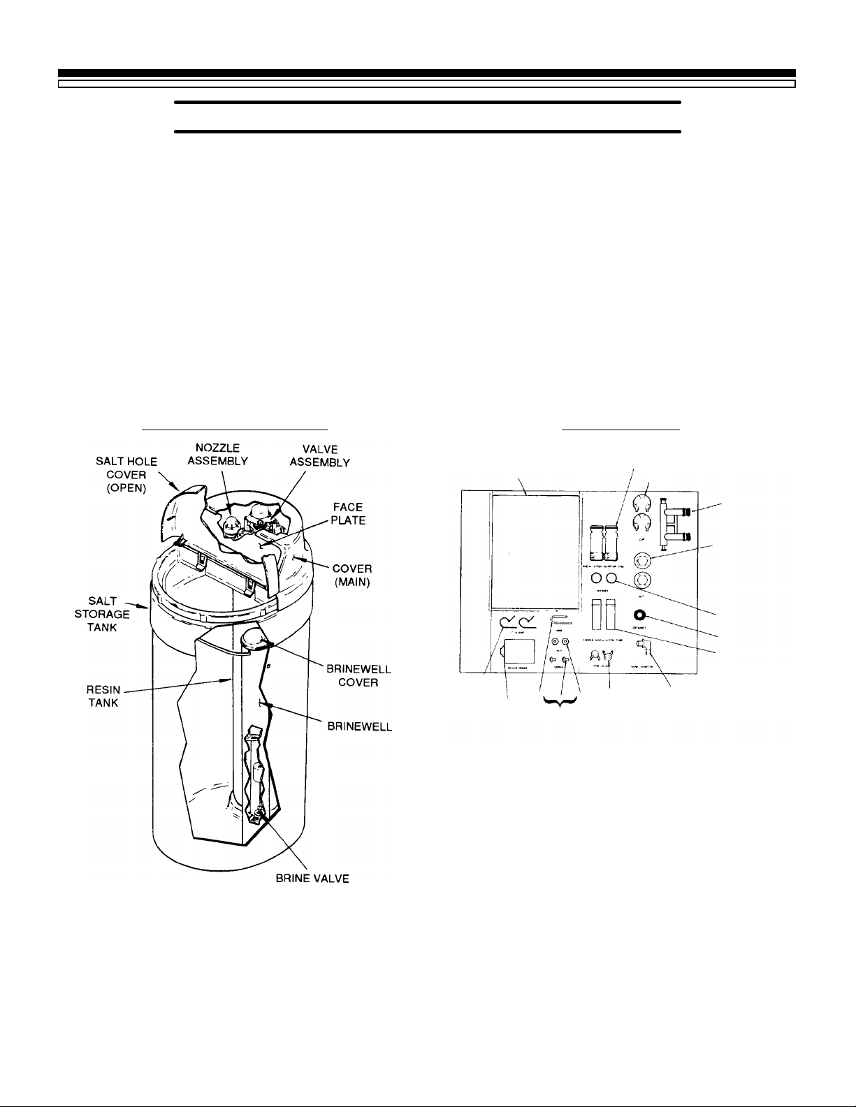
PARTS DESCRIPTIONS SMALL PARTS
Use care when handling the softener. DO NOT
turn upside-down. DO NOT drop, or set on
sharp objects that could make a hole in the
bottom.Thewatersoftenerisheavyand toavoid
damage,orpersonal injury, do nottrytolift it or
move more than necessary. See page 15, when
you are ready to move it into installation
position.
INLET --- OUTLET*
MANUALS
ADAPTOR (2)
CLIP (2)
BYPASS VAL VE*
INLET --- OUTLET*
NUT (2)
GROUND
CLAMP (2)
TRANSFORMER
GROUNDWIRE,
SCREWS AND
NUTS
TUBE
CLAMP
TUBE
ADAPTOR
*PARTSNOT INCLUDED
WITH ALL MODELS
WASHER OR*
GASKET (2)
GROMMET
INLET --- OUTLET*
TUBE (2)
Page 6

SECTION 1
6
1C. WATER SYSTEM TESTS
BEFORE INSTALLING CHECKS AND TESTS
Has your water supply had a chemical analysis? Please see page 2.
CHECK YOUR WATER PRESSURE — For your
softener to work right, a water pressure of no
lower than 20 pounds per square inch (psi) is
needed in the house water pipes. The highest
pressureallowedin the water pipesis 120 psi.If
pressure is over 120 psi, buy and install a
pressurereducingvalveinthewaterinletpipeto
the softener.
NOTE:
If water pressure during the day is 100 psi or
more,pressureduringthe nightmaygoover120
psi. Adding a pressure reducing valve may
reduce the flow.
If you have a well water system, look at the
pressure gauge to find the water pressure. Call
your local water department if you have city
water.Theywilltellyouwhatthewaterpressure
is where you live.
CHECKYOUR WATERFLOW RATE—Awater
flowofatleast3gallonsper minute is needed.A
lower flow will keep your softener from workingaswell asitshould.Tomakeaneasy checkof
yourflowrate,dothefollowing.Youwillneeda
1 gallon container (can, jar, pail, etc.).
1. Fully open 2 cold water faucets close to the
point water enters the house.
2. With both faucets open, fill the gallon con-
tainer at 1 faucet while looking at a watchor
clock to see how many seconds it takes.
3. Empty the container and go to the second
faucet(besureBOTHfaucetsarestillon).Fill
the gallon container atthe second faucetand
see how many seconds it takes.
4. Turn off both faucets. Now add the number
of seconds it took to fill the container atboth
faucets.
5. A total of 90 seconds, or less, means the
system flow rate is good.
FOR FUTURE REFERENCE, ENTER RESULTS OF YOUR WATER SYSTEM TESTS IN THE
“FACTS AND FIGURES TO KEEP” TABLE IN YOUR OWNERS MANUAL.
Page 7

SECTION 2
7
PLAN YOUR INSTALLATION
2A. WHERE TO INSTALL THE SOFTENER
Think of the following points as you choose a
place to put your softener. (see FIG. 1).
· Place as close as possible to the pressuretank
(well water) or water meter (city water).
· Place as close as possible to a water drain
such as a floor drain, laundry tub, sump or
standpipe.
Y· Connect to the house main water pipe BE-
FORE THE WATER HEATER. Temperature
of water going through the softener must
not be more than 120°F (49°C). Hot water
willdamageinnersoftenerparts.Toreducethe
risk of hot water backup, piping between the
softener and water heater should be as long
as possible.
· Keep outside faucets on hard water to save
soft water and salt.
Y· Do not install in a place where the softener
could freeze. Freeze damage voids the warranty by Sears, Roebuck and Co.
Y· Put the softener in a place water damage is
leastlikelytooccurifitdevelopsa leak.Sears
orthemanufacturerwillnotrepairorpayfor
water damage.
Y· A 120V electrical outlet, to plug the trans-
former into is needed within 10 feet of the
softener (the softener has a 10 foot power
cable). Be sure the outlet and transformer
are in an inside place, to protect from wet
weather. Sothesoftener alwayshaselectrical
power, use a continuously “live” outlet, that
cannot be accidentally switched off.
Y· When installing in an outside location, you
must take the steps necessary to assure the
softener, installation plumbing, and wiring,
are as well protected from the elements,
contamination, vandalism, etc., as when
installed indoors.
Y· Keep the softener out of direct sunlight. The
sun’s heat can melt plastic parts.
FIG. 1 THE PROPER ORDER TO INSTALL WATER TREATING EQUIPMENT
(Shows sequence of equipment only — seldon, if ever, would all items be needed)
Page 8

SECTION 2
8
2B. TOOLS, PIPE AND FITTINGS, OTHER MATERIALS NEEDED
PLAN YOUR INSTALLATION
Youmustfirstdecidehowtoruninandoutpipes
to the softener. Look at your house main water
pipeatthepointyouwillconnectthesoftener.Is
the pipe soldered copper, glued plastic, or
threaded galvanized or brass? What is the pipe
size? What kind of pipe and fittings is it easiest
for you to work with, and what tools do you
have?
Now look at the common plans for in and out
piping on pages 10 (soldered copper) and 11
(threaded). Select the drawing best for you and
use it as a guide to plan whatmaterials you will
need. As you plan your in and out piping, keep
inmind the following check list. Thengetallthe
materials you will need before you start.
NOTE:
Use page 9 to make a plan drawing for your
specific installation.
Some models may include a plastic bypass
valve, an installation kit and a length of drain
tubing.
4 In and out pipes to the softener must be at
least 3/4 in. size. Some local codes may tell
youtousenolessthan1in.pipesize(seeNote
on pages 10 or 11). You should maintain the
same, or larger, pipesize as the water supply
pipe, up to the softener inlet and outlet.
4 Use copper,brass, or galvanized pipe and fit-
tings.Somecodes mayalsoallowCPVCplastic pipe.
4 Copper and galvanized pipe corrode fast
when connected together. Use pipe and fittings of the same material.
4 Sears haskits and bypass valvesyou can buy
to help make installing your softener easier.
See pages 10 and 11.
4 ALWAYS install a bypass valve or valves. Ei-
theruse3shut-offvalves, or 1ofSearsspecial
valves.Bypassvalves letyouturnoffwaterto
the softener if needed to make repairs, but
still have water in the house pipes.
4 Drain tubing (3/8 in. inside diameter) is
needed for valve and salt tank drains. See
steps 1 and 2 on pages 16 and 17. Somemodels include a length of drain tubing, or you
can buy it at most Sears stores.
Ifarigidvalvedrainisneededtocomplywith
plumbing codes, you canbuythe parts needed(seepage16)tochangethesoftenertoa1/2
in. copper tubing drain.
4 TOOLS NEEDED:—Common and cross
point(Phillips)screwdrivers,slipjointpliers
and a tape measure or rule. ALSO¼
¼for SOLDERED COPPER — tubing cutter,
propanetorch,solid-coreLEAD-FREEsolder,
paste flux, emery cloth, sandpaper or steel
wool.
¼for THREADED PIPE — hacksaw or pipe
cutter, pipe wrenches, pipe threading tool,
pipejointcompound approvedforuse on potable water.
¼forCPVCPLASTIC—hacksaw, adjustable
wrench, solvent cement approved for use on
potable water, primer.
4 You can buy adaptors to go from a copper or
threadedmainwaterpipetoCPVCinandout
pipe.
Page 9

SECTION 2
9
PLAN YOUR INSTALLATION
2B. PIPE AND FITTINGS, PLAN DRAWING
Page 10

SECTION 2
1
0
PLAN YOUR INSTALLATION
2C. TYPICAL SOLDERED COPPER (OR CPVC) IN AND OUT PIPES TO SOFTENER
FIG. 2
*NOTE:
For 1 in. plumbing connection, buy 2 sweat
adaptors (1 in. female thread x 1 in. sweat) and
plumbdirectly tothe inlet---outlet adaptorsor by passvalve. Threads onthe inlet---outlet adaptors
and bypass valve are 1 in. pipe thread. Do not
usetheinstallationkit,SearsStock No.42---3441,
or the flexible connectors, Sears Stock No.
42--- 34401.
CAUTION:
DO ALL SOLDERING BEFORE CONNECTING SWEAT ADAPTOR TO INLET---OUTLET
ADAPTORS OR BYPASS VAL VE.
copper tube
o--ring
nut
SEARS KITS AND VALVES TO MAKE
INSTALLING YOUR SOFTENER EASIER
BYPASS VALVE (Plastic)
1
Sears Stock No. 42--- 3437
(included with some models)
One, easy working valve takes the place of 3 separate valves.
INSTALLATION KIT
3
Sears Stock No. 42--- 3441
(included with some models)
FLEXIBLE CONNECTORS
Sears Stock No. 42--- 34401
Allows easy hook up even
if pipes are note exactly
aligned.
(CHECK LOCAL PLUMBING CODES)
BYPASS VALVE (Brass)
2
Sears Stock No. 42--- 3436
USE AS SHOWN IN ,
OR TO REPLACE THE
1² X 3/4² SWEAT
ADAPTORS IN AND .
CONNECT FROM IN-OUT
PIPES, AT DOTTED LINE,
DIRECTLY TO THE INLET
AND OUTLET ADAPTORS
OR TO BYP ASS VALVE ¡.
SEE , , AND .
A
A
B C
C
B
D
Page 11

SECTION 2
1
1
2C. TYPICAL THREADED IN AND OUT PIPES TO SOFTENER
FIG. 3
PLAN YOUR INSTALLATION
NOTE:
D
If you are planning a threaded plumbing installation, with a 3-valve bypass, use Fig. 2 A as a
guide. Use union fittings, as needed, to connect
the plumbing.
*NOTE:
For 1 in. plumbing connection, use a 1 in. threaded
straight connector.
Page 12

SECTION 3
1
2
STEP BY STEP GUIDES TO INST ALL
3A. ASSEMBLE INLET---OUTLET ADAPTORS, OR PLASTIC BYPASS VAL VE
1. Close the shut-off valve on the house main
water pipe, nearthe water meter or pressure
tank, to turn off the water.
2. Shutoffthegasorelectric supplytothewater
heater.
3. Open the highestandlowestwaterfaucetsin
your house to letwater drain from the pipes.
Close faucets after water has drained.
4. If not already done, remove all cardboard or
plasticpackingpiecesfrominside thesoftener. Set the cardboard liner (with parts for
installingfastenedto it)whereyou caneasily
see it, and get to parts as you need them.
Remove the salt
hole cover ------ lift
straight upward,
andthemaincover
------ pull outward
on 2 tabs to release. Set both
covers aside so
they will not get
scratched or broken.
5. INSTALL THE INLET AND OUTLET
ADAPTORS OR SEARS BYPASS VALVE.
STOCK NO. 42-3437 (FIG. 4, 5 AND 6).
NOTE:
If you will install the bypass valve (use following steps a and c), the adaptors are not used. If
youdo notinstallthebypassvalve,youmustuse
the adaptors (use following steps a and b).
a. Visuallycheckandremoveanyforeignmate-
rials from the valve inlet and outlet ports
(FIG. 4).
b. INLET AND OUTLET ADAPTORS (Adap-
tors and clips are on the cardboard liner).
Push the adaptors into the valve inlet and
outlet ports as faras they will go. Bothadaptors are the same and fit either valve port.
Snap the 2 large holding clips into place,
from the top down as shown.
CAUTION¼Be sure the clips snap firmly
into place so the adaptors will notpullout.
GO TO PAGE 14.
c. BYPASS VALVE STOCK NO. 42-3437
— If not already done, put a light coating of
silicone grease or Vaseline on the bypass
valve o-rings.
Pushthebypassvalveintothesoftenervalve
as far as it will go. Snap the 2 large holding
clips into place, from the top down as
shown.
CAUTION¼Be sure the clips snap firmly
into place so the bypass valve will not pull
out.
GO TO PAGE 15.
Page 13

SECTION 3
1
3
STEP BY STEP GUIDES TO INST ALL
3A. ASSEMBLE INLET---OUTLET ADAPTORS, OR PLASTIC BYPASS VAL VE
FIG. 4 INSTALLING INLET-OUTLET
ADAPTORS OR BYPASS VALVE
NOTE:
The softener includes either theadaptors, or the
bypass valve, depending on the model.
FIG. 5 INSTALLING HOLDING CLIP
FIG. 6 BYPASS VALVE TURNED
DOWNWARD
ELECTRONIC DEMAND MODELS ONLY
Be sure the turbine and support are firmly in
place in the valve outlet.
Page 14

SECTION 3
1
4
3B. INSTALL 3---VALVE BYPASS, OR SINGLE BRASS BYPASS VAL VE
STEP BY STEP GUIDES TO INST ALL
1. INSTALLING 3 VALVE BYPASS, OR
SEARS BYPASS VALVE, STOCK NO.
42-3436, AND PIPES (FIG. 7)
a. Cut the house main water pipe where you
willconnectthesoftener.Looselyputtogetherpipe,fittings,and the3valvesorSearsspecial bypass valve. Place valve(s) within easy
reach.
IMPORTANT:
When looking at the front of the softener, the
inlet is on the right side. If water in yourhouse
mainwaterpiperunsfromlefttoright,besureto
use a “cross-over” as shown on page 9.
b. When all pipe, fittings and valves make a
good fit together, tighten all threaded joints
(usepipedope onoutsidethreads),or solder.
FIG. 7 BYPASS VALVES
Page 15

SECTION 3
1
5
3C. LOCATE SOFTENER AND CONNECT PIPES
1. MOVE THE SOFTENER INTO PLACE
Movethesoftener intoplace,ontoa leveland
smoothsurface.If needed,putapieceof3/4²
plywood, at least 17² x 20², under the tank.
Thenputspacersunder the plywood to level
the softener. Do not put shims or spacers
directly under the tank, without the ply-
wood. The weight of the softener, when full
of salt and water, may cause the tank to
puncture or break at the shim or spacer.
To movethesoftener, gripundertheridge onthe
salt tank sidewall and carefully rock back and
forth, into position.
2. CONNECT THE SOFTENER (Refer to your
plandrawingon page 9, andtopage10or11.
Read the IMPORTANT note on page 14.
Then, measure, cut (thread if needed) and
put all pipe and fittings together up to the
main water pipe, or to the bypass valve(s)
you installed on page 14.
STEP BY STEP GUIDES TO INST ALL
FIG. 8 TYPICAL SOLDERING CONNEC-
TION
NOTE:
a. Include adaptors, reducers, union fittings,
*flexible connectors, installation kit, etc., as
needed.
b. Cut pipe lengths exact for correct aligning,
and to prevent stress on the softener valve.
c. Use pipe joint compound or Teflon tape on
outside pipe threads.
d. When all piping fits together¼
¼solder all sweat fittings.
¼prime and cement all CPVC joints.
¼tighten all threaded joints.
CAUTIONS:
Y Never solder fittings while connected to
non-metallic parts. Waituntilsolderedpipehas
cooled before connection (see fig. 8).
Y Be very careful when putting pipe fittings
onto the plastic threads of the softener adaptors, or the bypass valve. Do not cross thread,
and do not overtighten.
*Flexible connectors are not allowed in all areas. CHECK YOUR LOCAL CODES.
Page 16

SECTION 3
1
6
3D. CONNECT VAL VE AND SALT TANK DRAINS
STEP BY STEP GUIDES TO INST ALL
1. CONNECT THE VALVE DRAIN TUBING
Take a length of 3/8² inside diameter (I.D.)
drain tubing and attach 1 end to the drain
fitting (FIG. 9). Usea tube clamp tohold it in
place. Put the other end of the tubing over a
floor drain, into a laundry tub, standpipe, or
othersuitabledrain. Checkyourlocal codes.
IMPORTANT: (see FIG. 9)
Y Leave an air gapof about 1-1/2² between the
end of the tubing and the drain. This gap is
needed so you don’t get a back-flow of sewer
waterintothe softener.Do notputtheend of the
tubing into the drain or connect without the air
gap.
Y Place and support the tubing so it does not
kink or have sharp bends. So water pressure
doesnotcausethetubingto“whip”, tieorwireit
in place. Do not pinch the tubing shut. The
softener will not work if this drain tubing is
pinched, plugged, closed or restricted in any
way.
Y Keep the tubing lower than the drain fitting.
(In some homes, to get toa drain you must raise
the tubing and run it over-head. If you need an
overhead drain, do not raise the tubing more
than 8¢ above the floor. A copper drain tube is
best to use.)
COPPER DRAIN TUBE: The plumbing codes
where you live may say that you must use a
copper valve drain tube. A copper tube is also
best to use for an over-headdrain. Use a copper
drain tube if the softener is installed outside, or
in the sunlight. Heat from the sun makes many
kinds of rubber or plastic hose to soften, flatten
and close up.
Toadaptacopperdraintubetothesoftener,usea
hacksaw to cut the barbed end from the drain
fitting as Fig. 10 shows. Buy a compression
fitting(1/4in. femalepipethreadsx1/2in.O.D.
tube) and tube from your local hardware store.
FIG. 10 COPPER DRAIN TUBE
FIG. 9 DRAIN TUBING
tube
clamp
drain
fitting
grommet
NOTE: Overflow
drain tubing is
available from
Sears, Item No.
42-- -3433 (20 ft)
tube
adaptor
tube
clamp
overflow drain
tubing (see step 2,
top of page 17)
valve drain hose
(see step 1, above)
tie or wire
tubing in place
To drain point
other than
floor drain.
Support tubing
in place as
needed.
Page 17

SECTION 3
1
7
3D. CONNECT VAL VE AND SALT TANK DRAINS
STEP BY STEP GUIDES TO INST ALL
2. CONNECT SALT TANK OVERFLOW
TUBING
a. Take the rubber grommet, tube adaptor and
tubeclamp (FIG.9)thatareonthesmallparts
cardboard liner.
b. Push the grommet into the hole in the salt
tankwallsohalfisinside and half is outside.
c. Push the bigger end of the tube adaptor into
the grommet.
d. Push one end of a length of 3/8² I.D. tubing
onto the tube adaptor, using the tube clamp
to hold it in place. Put the other end of the
tubing over the floor drain.
IMPORTANT:
· Thesalttankoverflowisfor safetyonly.Ifthe
salt tank should overfill with water, the
overflow tubing carries it to the drain.
· Over-fillwatermust run downwardthrough
the tubing. Do not raise the tubing higher
than the grommetand tube adaptor (FIG. 9).
· Do not connect to the valvedraintubingyou
installed in step 1. Both drains must have a
separate length of tubing.
Page 18

SECTION 3
1
8
3E. PRESSURE TEST --- CHECK FOR LEAKS
STEP BY STEP GUIDES TO INST ALL
TESTING YOUR PLUMBING WORK FOR
WATER LEAKS.
CAUTION:
To avoid water or air pressure damage to
softener inner parts, and to flush pipe chips or
other residue from the water pipes, be sure to
do the following steps exactly as instructed.
Lookatthe pictureinFIG. 12 showing yourkind
of bypass valve(s).
1. Fully open 2 cold, soft water faucets nearby
the softener.
2. Place bypass valve(s) in “bypass” position.
On a single valve, slide the stem into BYPASS.Ona3-valvesystem,closetheinletand
outlet valves and open the bypass valve.
3. Fullyopenthehousemainwaterpipeshutoff
valve. Observe steady water flow from both
open faucets.
FIG. 11 HOUSE MAIN WATER SHUTOFF
VALVES
FIG. 12 BYPASS VALVE(S) SOFT WATER
SERVICE/HARD W ATER BYPASS
Bypassvalve(s)shouldalwaysremaininsoft
water service position. Position in “bypass”
only if needed for softener repairs.
4. Place bypass valve(s) in “service”, EXACTLY
as follows: Keep soft water faucets open.
a. SINGLEBYPASSVALVE:SLOWLY,slidethe
valve stem toward service, pausing several
times to allow the softener to pressurize
slowly.
b. 3-VALVE BYPASS: Fully close the bypass
valve and open the outlet valve. SLOWLY,
opentheinletvalve,pausingseveral times to
allow the softener to pressurize slowly.
5. After about 3 minutes, open a hot water
faucet for about 1 minute, or until all air is
expelled, then close.
6. Close both cold water faucets.
7. Check your plumbingwork for leaks andfix
right away if any are found. Be sure to
observe previous caution notes.
Page 19

SECTION 3
1
9
3F. GROUNDING, CONNECT TO ELECTRICAL POWER
STEP BY STEP GUIDES TO INST ALL
1. INSTALLGROUNDINGWIREBETWEEN
THE SOFTENER IN AND OUT PIPES
Thehousecoldwaterpipe(ironorcopper)is
often used to ground all electrical outlets in
the home. Outlets are grounded to protect
you from shock when you touch any electric
appliance plugged into the outlet. If you
didn’t install a 3-valve bypass, or a brass
single bypass valve (FIG. 12), the cold water
pipe ground is broken.
FIG. 13 COLD WATER PIPE GROUND
Torestoretheground,taketheclamps(2),screws
(2), nuts (2) and ground wire that are on the
cardboardliner. Install across the ironor copper
in and out pipes as shown in FIG. 13. Be sure
good contact is made between the pipe and the
clamps. Fasten the ground wiretightly between
the clamps.
FIG. 14 WATER METER JUMPER WIRE
IMPORTANT:
Be sure the cold water pipe has direct metal to
metal contact all the way to the ground. Plastic,
rubberorotherelectricallyinsulatingpartssuch
as hoses, fittings, washers or gaskets can break
2. ELECTRICAL POWER OUTLET FOR
YOUR SOFTENER
The softener works on 24 volt, 60 Hz electric
power. The included transformer changes
standard 120 volt AC house power to 24
volts. You must plug the transformer into a
120 volt outlet only. Be sure the outlet is
always “live” so someone cannot turn it off
by mistake.
the direct metal to metal contact. Also check the
water meter (city water) or the well pump.
Install #4 copper jumper wires, clamped tightly
on both ends, across insulated parts (FIG. 14).
NOTE:
The included transformer is made for inside use
only. Be sure the electrical outlet you plug the
transformerintoisinside,toprotectfromweather (see page 7).
Page 20

SECTION 3
2
0
STEP BY STEP GUIDES TO INST ALL
3F. CONNECT TO ELECTRICAL POWER
3. FASTENTHE POWERCABLE ANDPLUG
IN THE TRANSFORMER
Looking at FIG. 15, fasten the 2 power cable
lugs (1 under each screw) to the transformer
asshown.Tightenbothscrews.Thenplugthe
transformer into the electrical outlet.
INSTALL COVERS
FIG. 15 CONNECTING TRANSFORMER
After installing your water softener, replace the
covers. First, position the main covers on the
softener. Then, set the salt hole cover into the
main cover, as shown, and lower closed.
RESTART THE WATER HEATER
TURN ON THE GAS (OR ELECTRIC) SUPPLY TO THE WATER HEATER AND LIGHT THE PILOT.
NOTE:
Your new Sears softener is now softening the
waterforyourhouseholdneeds.However,your
WATER HEATER is filled with hard water. To
have fully soft water right away, you can drain
thewaterheatersoitrefillswithsoftwater,ifyou
YOURPLUMBINGAND ELECTRICALWORKISCOMPLETE.Nowgoto yourowners manualand
do the softener start-up steps¼setting the timer, filling the storage tank with salt, sanitizing, etc.
don’t drain it, it will take a few days before you
have fully soft water.
Todrainthewaterheater,openahotwaterfaucet
and let it run until the water runs cold. Then
close the faucet.
7159931 (Rev. 2/98)
 Loading...