

Kenmore N8MSL0701408A1, N8MSN0701408A1, N8MSN0451412A1, N8MSL1352116A1, N8MSN1352116A1 Installation Instructions Manual
...Page 1
These instructions must be read and understood completely before attempting installation.
Safety Labeling and Signal Words
DANGER, WARNING, CAUTION, and NOTE Signal Words in Manuals
The signal words DANGER, WARNING, CAUTION, and NOTE The signal word WARNING is used throughout this manual inthe
are used to identify levels of hazard seriousness. The signal word following manner:
DANGER isonly used on product labels to signify an immediate
hazard. The signal words WARNING, CAUTION, and NOTE will
be used on product labels and throughout this manual and other The signal word CAUTION is used throughout this manual in the
manual that may apply to the product, following manner:
DANGER - Immediate hazards which will result in severe person-
at injury or death.
WARNING - Hazards or unsafe practices which could result in
severe personal injury or death.
CAUTION - Hazards or unsafe practices which may result in or product labels.
minor personal injury or product or property damage.
NOTE - Used to highlight suggestions which wilt result in en- z_ Safety-alert symbol
hanced installation, reliability, or operation. When you see this symbol on the unit and in instructions or manu-
TABLE OF CONTENTS
DIMENSIONS ............................................... 3
SAFETY CONSIDERATIONS .................................. 3
INTRODUCTION ............................................ 4
CODES AND STANDARDS ................................... 5
SAFETY ................................................ 5
GENERAL INSTALLATION ................................ 5
COMBUSTION AND VENTILATION AIR ..................... 5
DUCT SYSTEMS ........................................ 5
ACOUSTICAL LINING AND FIBROUS GLASS DUCT ......... 5
GAS PIPING AND GAS PIPE PRESSURE TESTING .......... 5
ELECTRICAL CONNECTIONS ............................ 5
VENTING .............................................. 5
ELECTROSTATIC DISCHARGE (ESD) PRECAUTIONS ........... 5
LOCATION ................................................. 6
AIR FOR COMBUSTION AND VENTILATION .................... 7
INSTALLATION .............................................. 10
UPFLOW INSTALLATION ................................. 10
DOWNFLOW INSTALLATION ............................. 11
FILTER ARRANGEMENT ................................. 12
AIR DUCTS ............................................. 13
AIR DELIVERY - CFM .................................... 14
ELECTRICAL CONNECTIONS ............................ 20
115-V WIRING .......................................... 20
J-BOX RELOCATION .................................... 20
ELECTRICAL CONNECTION TO J-BOX .................... 20
ELECTRICAL DATA ...................................... 21
24-V WIRING ........................................... 22
ACCESSORIES ......................................... 22
VENTING .................................................. 23
GENERAL VENTING REQUIREMENTS ..................... 23
MASONRY CHIMNEY REQUIREMENTS .................... 24
APPLIANCE APPLICATION REQUIREMENTS ............... 26
ADDITIONAL VENTING REQUIREMENTS .................. 26
SIDEWALL VENTING .................................... 27
START-UP, ADJUSTMENT, AND SAFETY CHECK ............... 30
GENERAL .............................................. 30
START-UP PROCEDURES ............................... 30
ADJUSTMENTS ......................................... 31
SPEED SELECTION ..................................... 32
CHECK SAFETY CONTROLS ............................. 33
CHECKLIST ............................................ 34
ORIFICE SIZE AND MANIFOLD PRESSURE ................ 35
SERVICE AND MAINTENANCE PROCEDURES ................. 39
CARE AND MAINTENANCE ................................... 39
SEQUENCE OF OPERATION ................................. 43
WIRING DIAGRAM .......................................... 44
TROUBLESHOOTING GUIDE ................................. 45
Signal Words on Product Labeling
Signal words are used in combination with colors and/or pictures
als, be alert to the potential for personal injury.
Use of the AHRI Certified TM Mark indicates
a manufacturer's participation in the program.
For verification of certification for individual
IS09001
PERSONAL INJURY, AND/OR PROPERTY
DAMAGE HAZARD
Failure to carefully read and follow this warning could
result in equipment malfunction, property damage,
3ersonal injury and/or death.
Installation or repairs made by unqualified persons
could result in equipment malfunction, property
damage, personal injury and/or death.
The information contained in this manual is intended for
use by a qualified service technician familiar with safety
3rocedures and equipped with proper tools and test
instruments.
Installation must conform with local building codes and
with the Natural Fuel Gas Code (NFCG) NFPA
54/ANSI Z223.1, and National standards of Canada
CAN/CSA-B149.1 and .2 Natural Gas and Propane
Installation Codes.
INSTALLER: Affixthese instructions on or adjacent tothe furnace.
CONSUMER: Retain these instructions for future reference.
products, go to www.ahridirectory.org .
Portionsofthe text and tables are reprintedfrom NFPA54/ANSI Z223.t -20096), with permission of National FireProtectionAssociation, Quincy, MA02269 and American Gas Association,Washing-
ton, DC 20001. This reprinted material is not the complete and official position of the NFPAor ANSI, onthe referencedsubiect, which is represented only by the standard in itsentirety,
PrintedinU.S.A. 441 01 1402 02 May. 2012
Page 2
I-- 5 16/16
| [150.7]
/ r- s1/2
i ;,;o.tt'1:'
27W4
FO'LT]
331/4 J
NR FLOW
• d
@ @
L..._ L..._ L..._ L..._
L..._ L..._ L..._ L..._
L..._ L..._ L..._ L..._
L..._ L..._ L..._ L..._
L..._ L..._ L..._ L..._
L..._ L..._ L..._ L..._
L..._ L..._ L..._ L..._
L..._ L..._ L..._ L..._
L..._ L..._ L..._ L..._
Figure 1 - Dimensional Drawing
¢ 7/8"-_ t
¢1/2-_--_ b
THERMOS'rATWIRE
F 7
, I
pC.71
I I'
I ¢7_
21.6 6.1
BO_[S40.5] ps6.7]
INLET
28,39
['r_1.2]
29
['ne.o]
TOPOF_kSING I l l 41a/16
o
z
b
118/16
Ll_ll
_57_
p4t_l
"r_ I_ CAImNG
LOCATION
I
P
6 1_V16--
p7e.Sl
ST_
[148.S] Sa_S--
57110 [14,t.Sl
[lS'IH1 llVffl _
_ p,o.21
/ / /s[,=.=l
/ i" J.BOXPROVISION
I-
_88/8
[els]-7"1 A
' 111 : ¢,=
"l I ¢1_/4
s] _22 1/le
I [51.O] 1
___. [,t_s]
c
_7/8
[=21=]
ACC_
t 1
[.vz.oj m_4] l
1
1
t, .......... __4
--D_ _ _V4
BOTrOM RE11JRN [11kl]
WIDTH
NOTES:
1. Two additional 7/8-in. (22 mm) diameter holes are located in the top plate.
2. Minimum return-air openings at furnace, based on metal duct. If flex duct is used, see flex duct manufacturer's recommendations for equivalent diameters.
a. For 800 CFM-16-in. (406 mm) round or 14 1/2 x 12-in. (368 x 305 mm) rectangle.
b. For 1200 CFM-20-in. (508 mm) round or 14 1/2 x 19 1/2-in. (368 x 495 mm) rectangle.
c. For 1600 CFM-22-in. (559 mm) round or 14 1/2 x 22 1/16-in. (368 x 560mm) rectangle.
d. For airflow requirements above 1800 CFM, see Air Delivery table in Product Data literature for specific use of single side inlets. The use of both side inlets, a
combination of 1 side and the bottom, or the bottom only will ensure adequate return air openings for airflow requirements above 1800 CFM.
2 441 01 1402 02
VEHTIHG(SPLACE8)
[r_
81DEINLET
(BOTHSlDF.m
147/8
la_.a]
I
(nOTH=,DES)
I
_A
L11/4
1 [Sl._]
[=r_]
Page 3
Table 1--Dimensions - In. (mm)
A
OUTLET
FURNACE SIZE
N8MSN & N8MSL
0451408
0451412
0701408
0701412
0701716
0901714
0902116
0902120
1101712
1102116
1102122
1352116
1352422
1552420
"135 and 155 size furnaces require a 5 or 6-in. (127 or 152 ram) vent.
installation requirements.
CABINET WIDTH
IN (mm)
14-3/16 (360)
14-3/16 (360)
14-3/16 (360)
14-3/16 (360)
17-1/2 (445)
17-1/2 (445)
21 (533)
21 (533)
17-1/2 (445)
21 (533)
21 (533)
21 (533)
24-1/2 (622)
24-1/2 (622) 22-7/8 (581)
WIDTH
IN (mm)
12-9/16 (319)
12-9/16 (319)
12-9/16 (319)
12-9/16 (319)
15-7/8 (403)
15-7/8 (403)
19-3/8 (492)
19-3/8 (492)
15-7/8 (403)
19-3/8 (492)
19-3/8 (492)
19-3/8 (492)
22-7/8 (581)
Use a vent adapter between furnace and vent stack. See Installation Instructions for complete
SAFETY CONSIDERATIONS
FIRE, EXPLOSION, ELECTRICAL SHOCK, AND
CARBON MONOXIDE POISONING HAZARD
Failure to follow this warning could result in personal
injury, death, or property damage.
Improper installation, adjustment, alteration, service,
maintenance, or use can cause carbon monoxide
poisoning, explosion, fire, electrical shock, or other
conditions which may cause personal injury or
property damage. Consult a qualified service agency,
local gas supplier, or your distributor or branch for
information or assistance. The qualified service
agency must use only factory-authorized and listed
kits or accessories when modifying this product.
FURNACE RELIABILITY HAZARD
Failure to follow this caution may result in unit
component damage.
Application of this furnace should be indoors with
special attention given to vent sizing and material,
gas input rate, air temperature rise, unit leveling, and
unit sizing.
CUT HAZARD
Failure to follow this caution may result in personal
injury.
Sheet metal parts may have sharp edges or burrs.
Use care and wear appropriate protective clothing,
safety glasses and gloves when handling parts, and
servicin,q furnaces.
Improper installation, adjustment, alteration, service,
maintenance, or use can cause explosion, fire, electrical
C
TOP AND
BOTTOM
FLUE COLLAR
IN (mm)
9-5/16 (237)
9-5/16 (237)
9-5/16 (237)
9-5/16 (237)
11-9/16 (294)
11-9/16 (294)
13-5/16 (338)
13-5/16 (338)
11-9/16 (294)
13-5/16 (338)
13-5/16 (338)
13-5/16 (338)
15-1/16 (383)
15-1/16 (383) 23 (584) 4 (102)* 170 (77)
BOTTOM
WIDTH
IN (mm)
12-11/16 (322)
12-11/16 (322)
12-11/16 (322)
12-11/16 (322)
16 (406)
16 (406)
19-1/2 (495)
19-1/2 (495)
16 (406)
19-1/2 (495)
19-1/2 (495)
19-1/2 (495)
23 (584)
VENT
CONNECTION
SIZE*
IN (mm)
4 (102)
4 (102)
4 (102)
4 (102)
4 (102)
4 (102)
4 (102)
4 (102)
4 (102)
4 (102)
4 (102)
4 (102)*
4 (102)*
SHIP WT
LB(KG)
104 (47)
107 (49)
111(50)
115 (52)
126 (57)
127 (58)
140 (64)
146 (66)
135 (61)
146 (66)
152 (69)
149 (68)
163 (74)
shock, or other conditions which may cause death, personal
injury, or property damage. Consult a qualified installer,
service agency, or your distributor or branch for information or
assistance. The qualified installer or agency must use
factory-authorized kits or accessories when modifying this
product. Refer to the individual instructions packaged with
the kits or accessories when installing.
Follow all safety codes. Wear safety glasses, protective
clothing, and work gloves. Have a fire extinguisher available.
Read these instructions thoroughly and follow all warnings or
cautions include in literature and attached to the unit. Consult
local building codes, the current editions of the National Fuel
Gas Code (NFGC) NFPA 54/ANSI Z223.1 and the National
Electrical Code (NEC) NFPA 70.
Recognize safety information. This is the safety-alert symbol
/_. When you see this symbol on the unit and in instructions
or manuals, be alert to the potential for personal injury.
Understand the signal words DANGER, WARNING, and
CAUTION. These words are used with the safety-alert
symbol. DANGER identifies the most serious hazards which
will result in severe personal injury or death. WARNING
signifies hazards which could result in personal injury or
death. CAUTION is used to identify unsafe practices which
may result in minor personal injury or product and property
damage. NOTE is used to highlight suggestions which will
result in enhanced installation, reliability, or operation.
1. Use only with type of gas approved for this furnace.
Refer to the furnace rating plate.
2. Install this furnace only in a location and position as
specified in the "Location" section of these instructions.
3. Provide adequate combustion and ventilation air to the
furnace space as specified in "Air for Combustion and
Ventilation" section.
4. Combustion products must be discharged outdoors.
Connect this furnace to an approved vent system only,
as specified in the "Venting" section of these instruc-
tions.
5. Never test for gas leaks with an open flame. Use a
commercially available soap solution made specifically
for the detection of leaks to check all connections, as
specified in the "Gas Piping" section.
6. Always install furnace to operate within the furnace's
intended temperature-rise range with a duct system
441 01 1402 02 3
Page 4
whichhasanexternalstaticpressurewithintheallow-
ablerange,asspecifiedinthe"Start-Up,Adjustments,
andSafetyCheck"section.Seefurnaceratingplate.
7.Whenafurnaceisinstalledsothatsupplyductscarry
aircirculatedbythefurnacetoareasoutsidethespace
containingthefurnace,thereturnairshallalsobe
handledbyduct(s)sealedtothefurnacecasingand
terminatingoutsidethespacecontainingthefurnace.
See"AirDucts"section.
8.Agas-firedfurnaceforinstallationinaresidentialgar-
agemustbeinstalledasspecifiedinthewarningboxin
the"Location"section.
9.Thefurnacemaybe usedfor constructionheat
providedthatthefurnaceinstallationandoperation
complieswiththefirstCAUTIONintheLOCATIONsec-
tionoftheseinstructions.
10.TheseMultipoiseGas-FiredFurnacesare CSA
(formerlyA.G.A.andC.G.A.)design-certifiedforuse
withnaturalandpropanegases(seefurnacerating
plate)andforinstallationinalcoves,attics,basements,
closets,utilityrooms,crawlspaces,andgarages.The
furnaceisfactory-shippedforusewithnaturalgas.A
CSA(A.G.A.andC.G.A.)listedaccessorygasconver-
sionkitisrequiredtoconvertfurnaceforusewithpro-
panegas.
11.SeeFigure1 forrequiredclearancesto combustible
construction.
12.Maintaina1-in.(25mm)clearancefromcombustible
materialstosupplyairductworkfora distanceof36in.
Figure 2 - Clearances to Combustibles
(914mm)horizontallyfromthefurnace.SeeNFPA90B
orlocalcodeforfurtherrequirements.
13.ThesefurnacesSHALLNOTbeinstalleddirectlyon
carpeting,tile,oranyothercombustiblematerialother
thanwoodflooring.In downflowinstallations,factory
accessoryfloorbaseMUSTbeusedwheninstalledon
combustiblematerialsandwoodflooring.Specialbase
isnotrequiredwhenthisfurnaceisinstalledonmanu-
facturer'scoilmodelnumbersEND4X,ENW4Xor
whencoilcasingmodelnumberNAEAis used.See
Figure1forclearancetocombustibleconstructionin-
formation.
INTRODUCTION
N8MSN & N8MSL 4-way multipoise Category I fan-assisted
furnace is CSA design-certified. A Category I fan-assisted
furnace is an appliance equipped with an integral mechanical
means to either draw or force products of combustion through
the combustion chamber and/or heat exchanger. The furnace
is factory-shipped for use with natural gas. This furnace is
not approved for installation in mobile homes, recreational
vehicles, or outdoors.
This furnace is designed for minimum continuous return-air
temperature of 60°F (16°0) db or intermittent operation down
to 55_'F (13°0) db such as when used with a night setback
thermostat. Return-air temperature must not exceed 80°F
(27°0) db. Failure to follow these return-air temperature limits
may affect reliability of heat exchangers, motors, and
controls. (See Figure 3)
Improper adjustment, alteration, service,
maintenance, or installation can cause
serious injury or death,
Read and follow instructions and
arecautions in User's Information Manual
erovided with this furnace. Installation
and service must be performed by a
qualified service agency or the gas
supplier,
_IL CAUTION
Check entire gas assembly for leaks after
lighting this appliance.
I INSTALLATION I
1. This furnace must be installed in
accordance with the manufacturer's
instructions and local codes. In the
absence of local codes, follow the National
Fuel Gas Code ANSI Z223.1 / NFPA54
or CSA B-149.1 Gas Installation Code.
2. This furnace must be installed so there are
previsions for combustion and ventilation
air. See manufacturer's installation
information provided with this appliance.
I OPERATION I
This furnace is equipped with manual reset
limit switch(es) in burner compartment to
protect against overheat conditions that
can result from inadequate combustion air
supply or blocked vent conditions.
1. Do not bypass limit switches.
2. If a limit opens, call a quallified
serviceman to correct the condition
and reset limit switch.
MINIMUM INCHES CLEARANCE TO COMBUSTIBLE CONSTRUCTION
This forced air furnace is This furnace is approved for
equipped for use with natural HORIZONTAL installations,
gas at altitudes 0 - 10,000 ft
(0 - 3,050m), Clearancearrows
An accessory kit, supplied by furnaceorientation
the manufacturer, shall be used
to convert to propane gas use
or may be required for some
natural gas applications.
This furnace is for indoor
installation in a building
constructed on site.
This furnace may be installed
on combustible flooring in alcove
or closet at minimum clearance
as indicated by the diagram
from combustible material.
This furnace may be used with Clearancein inches
a Type B-1 Vent and may be VentOlearancetocombustibles:
vented in common with other For Single Wall vents 6 inches (6 po).
gas fired appliances. For Type B-1vent type 1 inch (1 po).
DOWNFLOW POSITIONS:
1" Installation on non-combustible floors only.
For Installation on combustible flooring only when installed on special
base, Part No. KGASB0201ALL or NAHAO1101SB, Coil Assembly,
Part No. CAR, CAP, CNPV, CNRV, END4X, ENW4X, WENC, WTNC,
WENW OR WTNW.
18 inches front clearance required for alcove.
* Indicates supply or return sides when furnace is in the horizontal
position. Line contact only permissible between lines formed by
intersections of the Top and two Sides of the furnace jacket,
and building joists, studs or framing.
I INSTALLATION I
UPFLOW, DOWNFLOW, and
do not change with
MINIMUM INCHES CLEARANCE TO
COMBUSTIBLE CONSTRUCTION
IIIIIIIIIHMIMHI
336996-101 REV. C
4 441 01 1402 02
Page 5
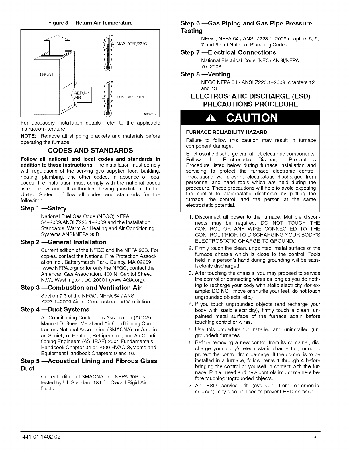
Figure 3 - Return Air Temperature
MAX 8OoF/27 oO
FRONT
"< :/ MIN 60°F/16°C
A06745
For accessory installation details, refer to the applicable
instruction literature.
NOTE: Remove all shipping brackets and materials before
operating the furnace.
CODES AND STANDARDS
Follow all national and local codes and standards in
addition to these instructions. The installation must comply
with regulations of the serving gas supplier, local building,
heating, plumbing, and other codes. In absence of local
codes, the installation must comply with the national codes
listed below and all authorities having jurisdiction. In the
United States , follow all codes and standards for the
following:
Step 1 --Safety
National Fuel Gas Code (NFGC) NFPA
54-2009/ANSI Z223.1-2009 and the Installation
Standards, Warm Air Heating and Air Conditioning
Systems ANSl/NFPA 90B
Step 2--General Installation
Current edition of the NFGC and the NFPA 90B. For
copies, contact the National Fire Protection Associ-
ation Inc., Batterymarch Park, Quincy, MA 02269;
(www.NFPA.org) or for only the NFGC, contact the
American Gas Association, 400 N. Capitol Street,
N.W., Washington, DO 20001 (www.AGA.org).
Step 3 --Combustion and Ventilation Air
Section 9.3 of the NFGC, NFPA 54/ANSI
Z223.1-2009 Air for Combustion and Ventilation
Step 4--Duct Systems
Air Conditioning Contractors Association (ACCA)
Manual D, Sheet Metal and Air Conditioning Con-
tractors National Association (SMACNA), or Americ-
an Society of Heating, Refrigeration, and Air Condi-
tioning Engineers (ASHRAE) 2001 Fundamentals
Handbook Chapter 34 or 2000 HVAC Systems and
Equipment Handbook Chapters 9 and 16.
--Acoustical Lining and Fibrous GlassStep 5
Duct
Current edition of SMACNA and NFPA 90B as
tested by UL Standard 181 for Class I Rigid Air
Ducts
Step 6--Gas Piping and Gas Pipe Pressure
Testing
NFGC; NFPA 54 /ANSI Z223.1-2009 chapters 5, 6,
7 and 8 and National Plumbing Codes
Step 7--Electrical Connections
National Electrical Code (NEC) ANSI/NFPA
70-2008
Step 8--Venting
NFGC NFPA 54/ANSI Z223.1-2009; chapters 12
and 13
ELECTROSTATIC DISCHARGE (ESD)
PRECAUTIONS PROCEDURE
FURNACE RELIABILITY HAZARD
Failure to follow this caution may result in furnace
component damage.
Electrostatic discharge can affect electronic components.
Follow the Electrostatic Discharge Precautions
Procedure listed below during furnace installation and
servicing to protect the furnace electronic control.
Precautions will prevent electrostatic discharges from
personnel and hand tools which are held during the
procedure. These precautions will help to avoid exposing
the control to electrostatic discharge by putting the
furnace, the control, and the person at the same
electrostatic potential.
1. Disconnect all power to the furnace. Multiple discon-
nects may be required. DO NOT TOUCH THE
CONTROL OR ANY WIRE CONNECTED TO THE
CONTROL PRIOR TO DISCHARGING YOUR BODY'S
ELECTROSTATIC CHARGE TO GROUND.
2. Firmly touch the clean, unpainted, metal surface of the
furnace chassis which is close to the control. Tools
held in a person's hand during grounding wilt be satis-
factorily discharged.
3. After touching the chassis, you may proceed to service
the control or connecting wires as long as you do noth-
ing to recharge your body with static electricity (for ex-
ample; DO NOT move or shuffle your feet, do not touch
ungrounded objects, etc.).
4. If you touch ungrounded objects (and recharge your
body with static electricity), firmly touch a clean, un-
painted metal surface of the furnace again before
touching control or wires.
5. Use this procedure for installed and uninstatled (un-
grounded) furnaces.
6. Before removing a new control from its container, dis-
charge your body's electrostatic charge to ground to
protect the control from damage. If the control is to be
installed in a furnace, follow items 1 through 4 before
bringing the control or yourself in contact with the fur-
nace. Put all used and new controls into containers be-
fore touching ungrounded objects.
7. An ESD service kit (available from commercial
sources) may also be used to prevent ESD damage.
441 01 1402 02 5
Page 6
LOCATION
CARBON MONOXIDE POISONING AND UNIT
DAMAGE HAZARD
Failure to follow this warning could result in personal
injury or death, and unit component damage.
Corrosive or contaminated air may cause failure of parts
containing flue gas, which could leak into the living
space. Air for combustion must not be contaminated by
halogen compounds, which include fluoride, chloride,
bromide, and iodide. These elements can corrode heat
exchangers and shorten furnace life. Air contaminants
are found in aerosol sprays, detergents, bleaches,
cleaning solvents, salts, air fresheners, and other
household products. Do not install furnace in a corrosive
or contaminated atmosphere. Make sure all combustion
and circulating air requirements are met, in addition to
all local codes and ordinances.
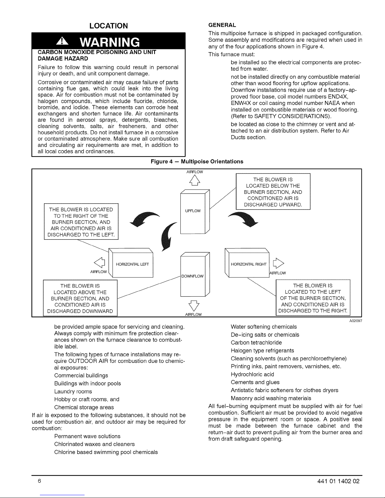
Figure 4 - Multipoise Orientations
THE BLOWER IS LOCATED
TOTHE RIGHT OFTHE
BURNERSECTION, AND
AiR CONDITIONED AIR IS
DISCHARGEDTO THE LEFT.
GENERAL
This multipoise furnace is shipped in packaged configuration.
Some assembly and modifications are required when used in
any of the four applications shown in Figure 4.
This furnace must:
be installed so the electrical components are protec-
ted from water.
not be installed directly on any combustible material
other than wood flooring for upflow applications.
Downflow installations require use of a factory-ap-
proved floor base, coil model numbers END4X,
ENW4X or coil casing model number NAEA when
installed on combustible materials or wood flooring.
(Refer to SAFETY CONSIDERATIONS).
be located as close to the chimney or vent and at-
tached to an air distribution system. Refer to Air
Ducts section.
AIRFLOW
THE BLOWER IS
LOCATED BELOWTHE
BURNERSECTION, AND
CONDITIONED AIR IS
DISCHARGED UPWARD.
LOCATEDABOVETHE
BURNER SECTION, AND
THE BLOWER IS '_7
CONDITIONEDAIR IS
DISCHARGED DOWNWARD
be provided ample space for servicing and cleaning.
Always comply with minimum fire protection clear-
ances shown on the furnace clearance to combust-
ible label.
The following types of furnace installations may re-
quire OUTDOOR AIR for combustion due to chemic-
al exposures:
Commercial buildings
Buildings with indoor pools
Laundry rooms
Hobby or craft rooms, and
Chemical storage areas
If air is exposed to the following substances, it should not be
used for combustion air, and outdoor air may be required for
combustion:
Permanent wave solutions
Chlorinated waxes and cleaners
Chlorine based swimming pool chemicals
AIRFLOW
_ HORIZONTAL RIGH_AIRF L_C w
THE BLOWER IS
LOCATED TO THE LEFT
OF THE BURNER SECTION,
AND CONDiTiONED AIR IS
DISCHARGED TO THE RIGHT.
A02097
Water softening chemicals
De-icing salts or chemicals
Carbon tetrachloride
Halogen type refrigerants
Cleaning solvents (such as perchloroethylene)
Printing inks, paint removers, varnishes, etc.
Hydrochloric acid
Cements and glues
Antistatic fabric softeners for clothes dryers
Masonry acid washing materials
All fuel-burning equipment must be supplied with air for fuel
combustion. Sufficient air must be provided to avoid negative
pressure in the equipment room or space. A positive seal
must be made between the furnace cabinet and the
return-air duct to prevent pulling air from the burner area and
from draft safeguard opening.
6 441 01 1402 02
Page 7
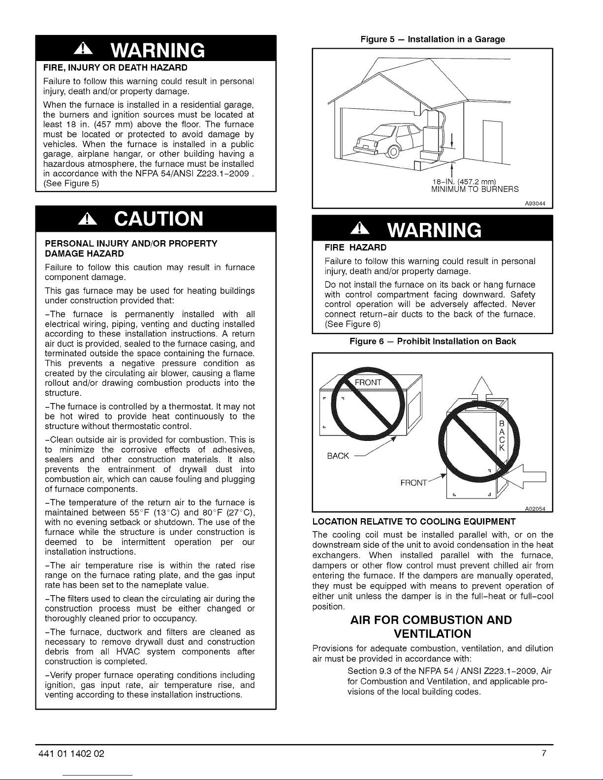
FIRE, INJURY OR DEATH HAZARD
Failure to follow this warning could result in personal
injury, death and/or property damage.
When the furnace is installed in a residential garage,
the burners and ignition sources must be located at
least 18 in. (457 mm) above the floor. The furnace
must be located or protected to avoid damage by
vehicles. When the furnace is installed in a public
garage, airplane hangar, or other building having a
hazardous atmosphere, the furnace must be installed
in accordance with the NFPA 54/ANSI Z223.1-2009.
(See Figure 5)
Figure 5 - Installation in a Garage
18-1N. (457.2 mm)
MINIMUM TO BURNERS
A93044
PERSONAL INJURY AND/OR PROPERTY
DAMAGE HAZARD
Failure to follow this caution may result in furnace
component damage.
This gas furnace may be used for heating buildings
under construction provided that:
-The furnace is permanently installed with all
electrical wiring, piping, venting and ducting installed
according to these installation instructions. A return
air duct is provided, sealed to the furnace casing, and
terminated outside the space containing the furnace.
This prevents a negative pressure condition as
created by the circulating air blower, causing a flame
rollout and/or drawing combustion products into the
structure.
-The furnace is controlled by a thermostat. It may not
be hot wired to provide heat continuously to the
structure without thermostatic control.
-Clean outside air is provided for combustion. This is
to minimize the corrosive effects of adhesives,
sealers and other construction materials. It also
prevents the entrainment of drywall dust into
combustion air, which can cause fouling and plugging
of furnace components.
-The temperature of the return air to the furnace is
maintained between 55°F (13°C) and 80°F (27°C),
with no evening setback or shutdown. The use of the
furnace while the structure is under construction is
deemed to be intermittent operation per our
installation instructions.
-The air temperature rise is within the rated rise
range on the furnace rating plate, and the gas input
rate has been set to the nameplate value.
-The filters used to clean the circulating air during the
construction process must be either changed or
thoroughly cleaned prior to occupancy.
-The furnace, ductwork and filters are cleaned as
necessary to remove drywall dust and construction
debris from all HVAC system components after
construction is completed.
-Verify proper furnace operating conditions including
ignition, gas input rate, air temperature rise, and
venting according to these installation instructions.
FIRE HAZARD
Failure to follow this warning could result in personal
injury, death and/or property damage.
Do not install the furnace on its back or hang furnace
with control compartment facing downward. Safety
control operation will be adversely affected. Never
connect return-air ducts to the back of the furnace.
(See Figure 6)
Figure 6 - Prohibit Installation on Back
BACK
A02054
LOCATION RELATIVE TO COOLING EQUIPMENT
The cooling coil must be installed parallel with, or on the
downstream side of the unit to avoid condensation in the heat
exchangers. When installed parallel with the furnace,
dampers or other flow control must prevent chilled air from
entering the furnace. If the dampers are manually operated,
they must be equipped with means to prevent operation of
either unit unless the damper is in the full-heat or full-cool
position.
AIR FOR COMBUSTION AND
VENTILATION
Provisions for adequate combustion, ventilation, and dilution
air must be provided in accordance with:
Section 9.3 of the NFPA 54/ANSI Z223.1-2009, Air
for Combustion and Ventilation, and applicable pro-
visions of the local building codes.
441 01 1402 O2 7
Page 8
2. Figure 7 illustrates how to provide TWO OUTDOOR
OPENINGS, one inlet and one outlet combustion and
ventilation air opening, to the outdoors.
FURNACE CORROSION HAZARD
Failure to follow this caution may result in furnace
damage.
Air for combustion must not be contaminated by
halogen compounds, which include fluoride, chloride,
bromide, and iodide. These elements can corrode
heat exchangers and shorten furnace life. Air
contaminants are found in aerosol sprays,
detergents, bleaches, cleaning solvents, salts, air
fresheners, and other household products.
a. One opening MUST commence within 12 in. (300
mm) of the ceiling and the second opening MUST
commence within 12 in. (300 mm) of the floor.
b. Size openings and ducts per Figure 7 and Table 2.
c. TWO HORIZONTAL DUCTS require 1 sq./in, of free
area per 2,000 Btuh (1,100 mm2/kW) of combined
input for all gas appliances in the space per
Figure 7 and Table 2.
d. TWO OPENINGS OR VERTICAL DUCTS require 1
sq./in, of free area per 4,000 Btuh (550 mm2/kW)
for combined input of all gas appliances in the
space per Figure 7 and Table 2.
CARBON MONOXIDE POISONING HAZARD
Failure to follow this warning could result in personal
injury or death.
The operation of exhaust fans, kitchen ventilation
fans, clothes dryers, attic exhaust fans or fireplaces
could create a NEGATIVE PRESSURE CONDITION
at the furnace. Make-up air MUST be provided for the
ventilation devices, in addition to that required by the
furnace. Refer to Carbon Monoxide Poisoning Hazard
warning in venting section of these instructions to
determine if an adequate amount of make-up air is
available.
3. ONE OUTDOOR OPENING requires:
a. 1 square inch of free area per 3,000 Btuh (734
mm2/kW) for combined input of all gas appliances
in the space per Table 2 and
b. Not less than the sum of the areas of all vent con-
nectors in the space.
The opening shall commence within 12 in. (300 mm) of the
ceiling. Appliances in the space shall have clearances of at
least 1 in. (25 mm) from the sides and back and 6 in. (150
mm) from the front. The opening shall directly communicate
with the outdoors or shall communicate through a vertical or
horizontal duct to the outdoors or spaces (crawl or attic) that
freely communicate with the outdoors.
The requirements for combustion and ventilation air depend
upon whether or not the furnace is located in a space having
a volume of at least 50 cu/ft, per 1,000 Btuh input rating for all
gas appliances installed in the space.
Spaces having less than 50 cu/ft, per 1,000 Btuh
Indoor Combustion Air NFPA & AGA
Standard and Known-Air-Infiltration Rate Methods
Indoor air is permitted for combustion, ventilation, and
dilution, if the Standard or Known-Air-Infiltration Method
is used.
require the OUTDOOR COMBUSTION AIR
METHOD.
Spaces having at least 50 cu/ft, per 1,000 Btuh may
use the INDOOR COMBUSTION AIR, STANDARD
or KNOWN AIR INFILTRATION METHOD.
Outdoor Combustion Air Method
1. Provide the space with sufficient air for proper combus-
tion, ventilation, and dilution of flue gases using per-
manent horizontal or vertical duct(s) or opening(s) dir-
ectly communicating with the outdoors or spaces that
CARBON MONOXIDE POISONING HAZARD
Failure to follow this warning could result in death
and/or personal injury.
Many homes require air to be supplied from outdoors
for furnace combustion, ventilation, and dilution of flue
gases. The furnace combustion air supply must be
provided in accordance with this instruction manual.
freely communicate with the outdoors.
Table 2--Minimum Free Area Re(
TWO HORIZONTAL DUCTS SINGLE DUCT OR OPENING
FURNACE (1 SQ. IN./2,000 BTUH) (1 SQ. IN./3,000 BTUH)
INPUT (1,100 SQ. MM/KW) (734 SQ. MM/KW)
(BTUH) Free Area of Round Duct Free Area of Round Duct Free Area of Round Duct
Opening and Duct Dia. Opening and Duct Dia. Opening and Duct Dia.
Sq. In. (Sq. mm) In. (mm) Sq. In. (Sq. mm) In. (mm) Sq. In. (Sq. mm) In. (mm)
44,000 22 (14194) 6 (152) 14.7 (9484) 5 (127) 11 (7096) 4 (102)
66,000 33 (21290) 7 (178) 22.0 (14193) 6 (152) 16.5 (10645) 5 (127)
88,000 44 (28387) 8 (203) 29.3 (18903) 7 (178) 22 (14193) 6 (152)
110,000 55 (35484) 9 (229) 36.7 (23677) 7 (178) 27.5 (17742) 6 (152)
132,000 66 (42580) 10 (254) 44.0 (28387) 8 (203) 33 (21290) 7 (178)
154,000 77 (49677) 10 (254) 51.3 (33096) 9 (229) 38.5 (24839) 8 (203)
uired for Each Combustion Air Opening of Duct to Outdoors
TWO OPENINGS OR VERTICAL
DUCTS
(1 SQ. IN./4,000 BTUH)
(550 SQ. MM/KW)
FURNACE WATER HEATER TOTAL INPUT
110,000 + 30,000 (140,000 divided by 4,000) = 35.0 Sq. In. for each two Vertical Ducts or Openings
66,000 + 40,000 (106,000 divided by 3,000) = 35.3 Sq. In.for a Single Duct or Opening
88,000 + 30,000 (118,000 divided by 2,000) = 59.0 Sq. In. for each of two Horizontal Ducts
8 441 01 1402 02
EXAMPLES: Determining Free Area
Page 9
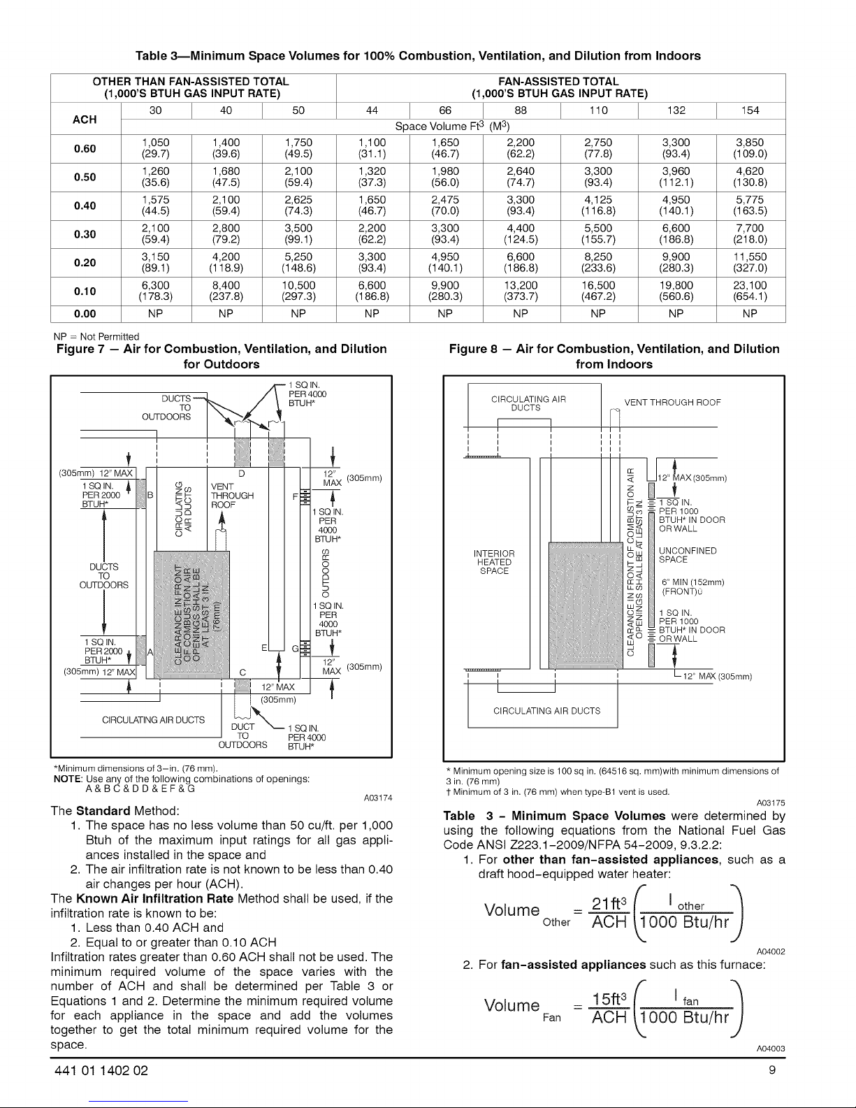
Table 3--Minimum Space Volumes for 100% Combustion, Ventilation, and Dilution from Indoors
OTHER THAN FAN-ASSISTED TOTAL FAN-ASSISTED TOTAL
(1,000'S BTUH GAS INPUT RATE) (1,000'S BTUH GAS INPUT RATE)
30 40 50 44 66 88 110 132 154
ACH Space Volume Ft3 (M3)
0.60 (29.7) (39.6) (49.5) (31.1) (46.7) (62.2) (77.8) (93.4) (109.0)
0.50 (35.6) (47.5) (59.4) (37.3) (56.0) (74.7) (93.4) (112.1 ) (130.8)
0.40 (44.5) (59.4) (74.3) (46.7) (70.0) (93.4) (116.8) (140.1 ) (163.5)
0.30 (59.4) (79.2) (99.1) (62.2) (93.4) (124.5) (155.7) (186.8) (218.0)
0.20 (89.1) (118.9) (148.6) (93.4) (140.1 ) (186.8) (233.6) (280.3) (327.0)
0.10 (178.3) (237.8) (297.3) (186.8) (280.3) (373.7) (467.2) (560.6) (654.1)
0.00 NP NP NP NP NP NP NP NP NP
NP = Not Permitted
Figure 7 -- Air for Combustion, Ventilation, and Dilution
1,050 1,400 1,750 1,100 1,650 2,200 2,750 3,300 3,850
1,260 1,680 2,100 1,320 1,980 2,640 3,300 3,960 4,620
1,575 2,100 2,625 1,650 2,475 3,300 4,125 4,950 5,775
2,100 2,800 3,500 2,200 3,300 4,400 5,500 6,600 7,700
3,150 4,200 5,250 3,300 4,950 6,600 8,250 9,900 11,550
6,300 8,400 10,500 6,600 9,900 13,200 16,500 19,800 23,100
Figure 8 - Air for Combustion, Ventilation, and Dilution
OUTDOORS
for Outdoors
TO
SQ IN.
PER 4000
BTUH*
from Indoors
VENT THROUGH ROOF
(305mm) 12" MAX
1 SQ IN.
PER 2000
BTUH*
DUCTS
TO
OUTDOORS
1 SQ IN.
PER 2000
BTUH*
(305mm)
(305mm)
CIRCULATING AIR DUCTS
TO PER 4000
OUTDOORS BTUH*
*Minimum dimensions of 3-in. (76 mm).
NOTE: Use any ofthe following combinations of openings:
A&BC&DD&EF&G
1 SQ IN.
12_X (305mm)
1 SQ IN.
PER
4000
BTUH*
O3
rr
O
O
a
F-
O
1 SQ IN.
PER
4000
BTUH*
12" (305mm)
MAX
The Standard Method:
1. The space has no less volume than 50 cu/ft, per 1,000
Btuh of the maximum input ratings for all gas appli-
ances installed in the space and
2. The air infiltration rate is not known to be less than 0.40
air changes per hour (ACH).
A03174
I I
INTERIOR
HEATED
SPACE
CIRCULATING AIR DUCTS
Minimum opening size is 100 sq in. (64516 sq. mm)with minimum dimensions of
in. (76 ram)
Minimum of 3 in. (76 mm) when type-B1 vent is used.
Table 3 - Minimum Space Volumes were determined by
using the following equations from the National Fuel Gas
Code ANSI 7223.1-2009/NFPA 54-2009, 9.3.2.2:
1. For other than fan-assisted appliances, such as a
draft hood-equipped water heater:
I
12" AX(305mm)
z
O
2_ 1 SQ IN.
BTUH* IN DOOR
i PER 1000
OR WALL
UNCONFINED
W SPACE
-4,
_: 6" MIN (152mm)
co (FRONT)0
_z 1 SQ IN.
PER 1000
_ BTUH* IN DOOR
OR WALL
L 12"MAX(305ram)
The Known Air Infiltration Rate Method shall be used, if the
infiltration rate is known to be:
1. Less than 0.40 ACH and
Vo'" m e Other: A-A0_ _k,T000 "a_/h r"#
2. Equal to or greater than 0.10 ACH
Infiltration rates greater than 0.60 ACH shall not be used. The
minimum required volume of the space varies with the
2. For fan-assisted appliances such as this furnace:
number of ACH and shall be determined per Table 3 or
Equations 1 and 2. Determine the minimum required volume
for each appliance in the space and add the volumes
together to get the total minimum required volume for the
V°lumeFan = ACH _000 Btu/hrJ
15ft3 f[ ]fan ="_
space.
441 01 1402 02 9
A03t 75
A04002
A04003
Page 10
If:
Iother= combinedinputof all otherthanfan-assisted
appliancesinBtuh/hr
Ifan= combinedinputof all fan-assistedappliancesin
Btuh/hrACH=airchangesperhour(ACHshallnotexceed
0.60.)Thefollowingrequirementsapplyto theStandard
MethodandtotheKnownAirInfiltrationRateMethod.
1.Adjoiningroomscanbeconsideredpartofaspaceif:
a.Therearenocloseabledoorsbetweenrooms.
b.Combiningspacesonsamefloorlevel.Eachopen-
ingshallhavefreeareaofatleast1in.2/1,000Btuh
(2,000mm2/kW)ofthetotalinputratingofallgas
appliancesinthespace,butnotlessthan100in.2
(0.06m2).Oneopeningshallcommencewithin12
in.(300mm)oftheceilingandthesecondopening
shallcommencewithin12in.(300mm)ofthefloor.
Theminimumdimensionofairopeningsshallbeat
least3in.(80mm).(SeeFigure8)
c.Combiningspaceondifferentfloorlevels.The
volumesofspacesondifferentfloorlevelsshallbe
consideredascommunicatingspacesifconnected
byoneormorepermanentopeningsindoorsor
floorshavingfreeareaofatleast2in.2/1,000Btuh
(4,400mm2/kW)oftotalinputratingofallgasappli-
ances.
2.Anatticorcrawlspacemaybeconsideredaspacethat
freelycommunicateswiththeoutdoorsprovidedthere
areadequatepermanentventilationopeningsdirectly
tooutdoorshavingfreeareaofat least1-in.2/4,000
Btuhoftotalinputratingforallgasappliancesinthe
space.
3.InspacesthatusetheIndoorCombustionAirMethod,
infiltrationshouldbeadequatetoprovideairforcom-
bustion,permanentventilationand dilutionof flue
gases.However,inbuildingswithunusuallytightcon-
struction,additionalairMUSTbeprovidedusingthe
methodsdescribedintheOutdoorCombustionAir
Methodsection.
UnusuallytightconstructionisdefinedasConstructionwith:
a.Wallsandceilingsexposedtotheoutdoorshavea
continuous,sealedvaporbarrier.Openingsaregas-
ketedorsealedand
b.Doorsandopenablewindowsareweatherstripped
and
c.Otheropeningsarecaulkedorsealed.Thesein-
cludejointsaroundwindowanddoorframes,
betweensoleplatesandfloors,betweenwall-ceil-
ingjoints,betweenwallpanels,atpenetrationsfor
plumbing,electricalandgaslines,etc.
CombinationofIndoorandOutdoorAir
1.IndooropeningsshallcomplywiththeIndoorCom-
bustionAirMethodbelowand,
2.Outdooropeningsshallbelocatedasrequiredinthe
OutdoorCombustionAir Methodmentionedprevi-
ouslyand,
3.Outdooropeningsshallbesizedasfollows:
a.CalculatetheRatioofallIndoorSpacevolumedi-
videdbyrequiredvolumeforIndoorCombustion
AirMethodbelow.
b.OutdooropeningsizereductionFactoris1minus
theRatioina.above.
c.MinimumsizeofOutdooropeningsshallbethesize
requiredinOutdoorCombustionAirMethod
abovemultipliedbyreductionFactorinb.above.
Theminimumdimensionofairopeningsshallbe
notlessthan3in.(80mm).
INSTALLATION
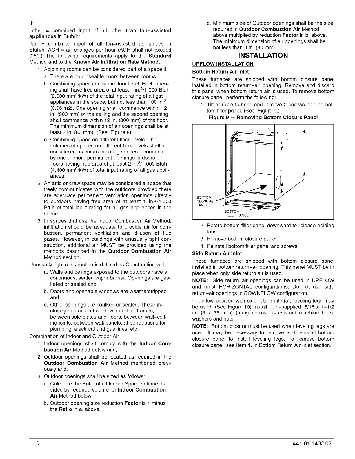
UPFLOW INSTALLATION
Bottom Return Air Inlet
These furnaces are shipped with bottom closure panel
installed in bottom return-air opening. Remove and discard
this panel when bottom return air is used. To remove bottom
closure panel, perform the following:
1. Tilt or raise furnace and remove 2 screws holding bot-
tom filler panel. (See Figure 9.)
Figure 9 -- Removing Bottom Closure Panel
I
I
#
I
BOTTOM
CLOSURE
PANEL
BOTTOM
FILLER PANEL
2. Rotate bottom filler panel downward to release holding
tabs.
3. Remove bottom closure panel.
4. Reinstall bottom filler panel and screws.
Side Return Air Inlet
These furnaces are shipped with bottom closure panel
installed in bottom return-air opening. This panel MUST be in
place when only side return air is used.
NOTE: Side return-air openings can be used in UPFLOW
and most HORIZONTAL configurations. Do not use side
return-air openings in DOWNFLOW configuration.
In upflow position with side return inlet(s), leveling legs may
be used. (See Figure 10) Install field-supplied, 5/16 x 1-1/2
in. (8 x 38 mm) (max) corrosion-resistant machine bolts,
washers and nuts.
NOTE: Bottom closure must be used when leveling legs are
used. It may be necessary to remove and reinstall bottom
closure panel to install leveling legs. To remove bottom
closure panel, see Item 1. in Bottom Return Air Inlet section.
P
10 441 01 1402 02
Page 11
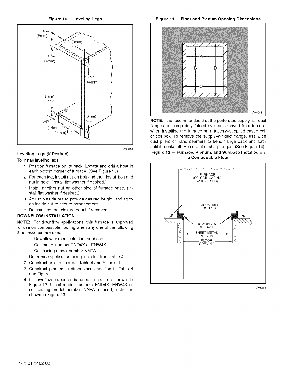
Figure 10 - Leveling Legs Figure 11 - Floor and Plenum Opening Dimensions
(8mm)
I
(44mm)
1 3/4"
(44mm)
(8mm)
5/16 _
(8mm)
(44mm) 1 3/4"
(44mm) I 3/4'_.
A89014
Leveling Legs (If Desired)
To install leveling legs:
1. Position furnace on its back. Locate and drill a hole in
each bottom corner of furnace. (See Figure 10)
2. For each leg, install nut on bolt and then install bolt and
nut in hole. (Install flat washer if desired.)
3. Install another nut on other side of furnace base. (In-
stall flat washer if desired.)
4. Adjust outside nut to provide desired height, and tight-
en inside nut to secure arrangement.
5. Reinstall bottom closure panel if removed.
DOWNFLOW INSTALLATION
NOTE: For downflow applications, this furnace is approved
for use on combustible flooring when any one of the following
3 accessories are used:
Downflow combustible floor subbase
Coil model number END4X or ENW4X
Coil casing model number NAEA
1. Determine application being installed from Table 4.
2. Construct hole in floor per Table 4 and Figure 11.
3. Construct plenum to dimensions specified in Table 4
and Figure 11.
4. If downflow subbase is used, install as shown in
Figure 12. If coil model numbers END4X, ENW4X or
coil casing model number NAEA is used, install as
shown in Figure 13.
A96283
NOTE: It is recommended that the perforated supply-air duct
flanges be completely folded over or removed from furnace
when installing the furnace on a factory-supplied cased coil
or coil box. To remove the supply-air duct flange, use wide
duct pliers or hand seamers to bend flange back and forth
until it breaks off. Be careful of sharp edges. (See Figure 14)
Figure 12 - Furnace, Plenum, and Subbase Installed on
a Combustible Floor
FURNACE
(OR COIL CASING
WHEN USED)
COMBUSTIBLE
FLOORING
DOWNFLOW
SUBBASE
SHEET METAL
PLENUM
__ FLOOR __
OPENING
A96285
441 01 1402 02 11
Page 12
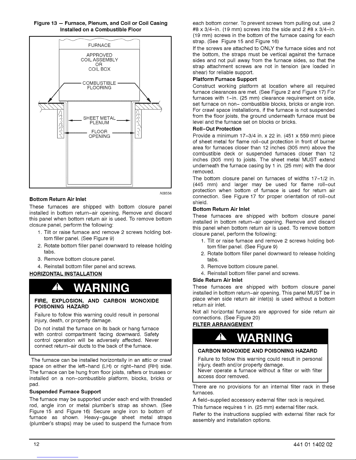
Figure 13 - Furnace, Plenum, and Coil or Coil Casing
Installed on a Combustible Floor
FURNACE
APPROVED
COIL ASSEMBLY
OR
COIL BOX
COMBUSTIBLE
FLOORING
\\\\_
_f,=====SHEET METAL =====.=_
I
Bottom Return Air Inlet
These furnaces are shipped with bottom closure panel
installed in bottom return-air opening. Remove and discard
this panel when bottom return air is used. To remove bottom
closure panel, perform the following:
1. Tilt or raise furnace and remove 2 screws holding bot-
tom filler panel. (See Figure 9)
2. Rotate bottom filler panel downward to release holding
tabs.
3. Remove bottom closure panel.
4. Reinstall bottom filler panel and screws.
HORIZONTAL INSTALLATION
FIRE, EXPLOSION, AND CARBON MONOXIDE
POISONING HAZARD
Failure to follow this warning could result in personal
injury, death, or property damage.
Do not install the furnace on its back or hang furnace
with control compartment facing downward. Safety
control operation will be adversely affected. Never
connect return-air ducts to the back of the furnace.
The furnace can be installed horizontally in an attic or crawl
space on either the left-hand (LH) or right-hand (RH) side.
The furnace can be hung from floor joists, rafters or trusses or
installed on a non-combustible platform, blocks, bricks or
pad.
Suspended Furnace Support
The furnace may be supported under each end with threaded
rod, angle iron or metal plumber's strap as shown. (See
Figure 15 and Figure 16) Secure angle iron to bottom of
furnace as shown. Heavy-gauge sheet metal straps
(plumber's straps) may be used to suspend the furnace from
PLENUM
FLOOR
OPENING
E
A08556
each bottom corner. To prevent screws from pulling out, use 2
#8 x 3/4-in. (19 mm) screws into the side and 2 #8 x 3/4-in.
(19 mm) screws in the bottom of the furnace casing for each
strap. (See Figure 15 and Figure 16)
If the screws are attached to ONLY the furnace sides and not
the bottom, the straps must be vertical against the furnace
sides and not pull away from the furnace sides, so that the
strap attachment screws are not in tension (are loaded in
shear) for reliable support.
Platform Furnace Support
Construct working platform at location where all required
furnace clearances are met. (See Figure 2 and Figure 17) For
furnaces with 1-in. (25 mm) clearance requirement on side,
set furnace on non- combustible blocks, bricks or angle iron.
For crawl space installations, if the furnace is not suspended
from the floor joists, the ground underneath furnace must be
level and the furnace set on blocks or bricks.
Roll-Out Protection
Provide a minimum 17-3/4 in. x 22 in. (451 x 559 mm) piece
of sheet metal for flame roll-out protection in front of burner
area for furnaces closer than 12 inches (305 mm) above the
combustible deck or suspended furnaces closer than 12
inches (305 mm) to joists. The sheet metal MUST extend
underneath the furnace casing by 1 in. (25 mm) with the door
removed.
The bottom closure panel on furnaces of widths 17-1/2 in.
(445 mm) and larger may be used for flame roll-out
protection when bottom of furnace is used for return air
connection. See Figure 17 for proper orientation of roll-out
shield.
Bottom Return Air Inlet
These furnaces are shipped with bottom closure panel
installed in bottom return-air opening. Remove and discard
this panel when bottom return air is used. To remove bottom
closure panel, perform the following:
1. Tilt or raise furnace and remove 2 screws holding bot-
tom filler panel. (See Figure 9)
2. Rotate bottom filler panel downward to release holding
tabs.
3. Remove bottom closure panel.
4. Reinstall bottom filler panel and screws.
Side Return Air Inlet
These furnaces are shipped with bottom closure panel
installed in bottom return-air opening. This panel MUST be in
place when side return air inlet(s) is used without a bottom
return air inlet.
Not all horizontal furnaces are approved for side return air
connections. (See Figure 20)
FILTER ARRANGEMENT
CARBON MONOXIDE AND POISONING HAZARD
Failure to follow this warning could result in personal
injury, death and/or property damage.
Never operate a furnace without a filter or with filter
access door removed.
There are no provisions for an internal filter rack in these
furnaces.
A field-supplied accessory external filter rack is required.
This furnace requires 1 in. (25 mm) external filter rack.
Refer to the instructions supplied with external filter rack for
assembly and installation options.
12 441 01 1402 02
Page 13
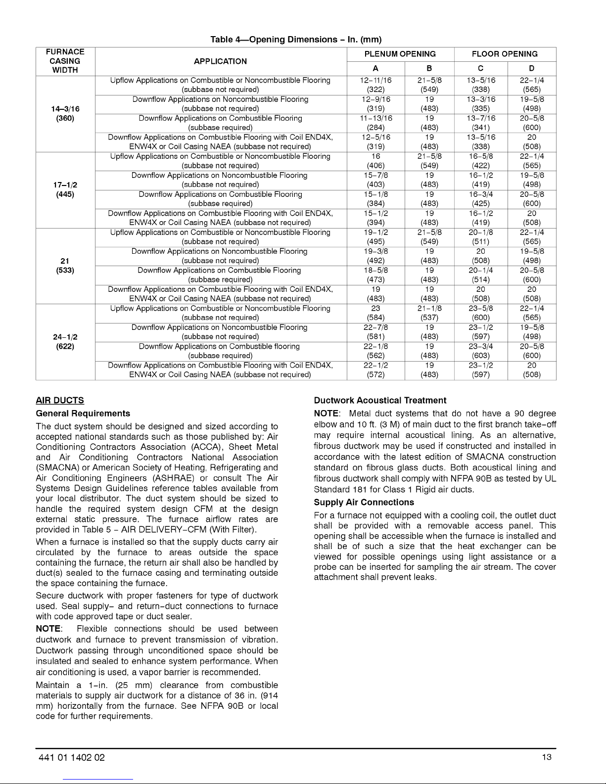
Table 4_Opening Dimensions - In. (mm)
FURNACE
CASING
WIDTH
Upflow Applications on Combustible or Noncombustible Flooring 12-11/16 21-5/8 13-5/16 22-1/4
Downflow Applications on Noncombustible Flooring 12-9/16 19 13-3/16 19-5/8
14-3/16 (subbase not required) (319) (483) (335) (498)
(360) Downflow Applications on Combustible Flooring 11-13/16 19 13-7/16 20-5/8
Downflow Applications on Combustible Flooring with Coil END4X, 12-5/16 19 13-5/16 20
ENW4X or Coil Casing NAEA (subbase not required) (319) (483) (338) (508)
Upflow Applications on Combustible or Noncombustible Flooring 16 21-5/8 16-5/8 22-1/4
Downflow Applications on Noncombustible Flooring 15-7/8 19 16-1/2 19-5/8
17-1/2 (subbase not required) (403) (483) (419) (498)
(445) Downflow Applications on Combustible Flooring 15-1/8 19 16-3/4 20-5/8
Downflow Applications on Combustible Flooring with Coil END4X, 15-1/2 19 16-1/2 20
ENW4X or Coil Casing NAEA (subbase not required) (394) (483) (419) (508)
Upflow Applications on Combustible or Noncombustible Flooring 19-1/2 21-5/8 20-1/8 22-1/4
Downflow Applications on Noncombustible Flooring 19-3/8 19 20 19-5/8
21 (subbase not required) (492) (483) (508) (498)
(533) Downflow Applications on Combustible Flooring 18-5/8 19 20-1/4 20-5/8
Downflow Applications on Combustible Flooring with Coil END4X, 19 19 20 20
ENW4X or Coil Casing NAEA (subbase not required) (483) (483) (508) (508)
Upflow Applications on Combustible or Noncombustible Flooring 23 21- 1/8 23-5/8 22-1/4
Downflow Applications on Noncombustible Flooring 22- 7/8 19 23-1/2 19-5/8
24-1/2 (subbase not required) (581) (483) (597) (498)
(622) Downflow Applications on Combustible flooring 22-1/8 19 23-3/4 20-5/8
Downflow Applications on Combustible Flooring with Coil EN D4X, 22-1/2 19 23-1/2 20
ENW4X or Coil Casing NAEA (subbase not required) (572) (483) (597) (508)
APPLICATION
(subbase not required) (322) (549) (338) (565)
(subbase required) (284) (483) (34t) (600)
(subbase not required) (406) (549) (422) (565)
(subbase required) (384) (483) (425) (600)
(subbase not required) (495) (549) (511) (565)
(subbase required) (473) (483) (514) (600)
(subbase not required) (584) (537) (600) (565)
(subbase required) (562) (483) (603) (600)
PLENUM OPENING FLOOR OPENING
A B C D
AIR DUCTS
General Requirements
The duct system should be designed and sized according to
accepted national standards such as those published by: Air
Conditioning Contractors Association (ACCA), Sheet Metal
and Air Conditioning Contractors National Association
(SMACNA) or American Society of Heating, Refrigerating and
Air Conditioning Engineers (ASHRAE) or consult The Air
Systems Design Guidelines reference tables available from
your local distributor. The duct system should be sized to
handle the required system design CFM at the design
external static pressure. The furnace airflow rates are
provided in Table 5 - AIR DELIVERY-CFM (With Filter).
When a furnace is installed so that the supply ducts carry air
circulated by the furnace to areas outside the space
containing the furnace, the return air shall also be handled by
duct(s) sealed to the furnace casing and terminating outside
the space containing the furnace.
Secure ductwork with proper fasteners for type of ductwork
used. Seal supply- and return-duct connections to furnace
with code approved tape or duct sealer.
NOTE: Flexible connections should be used between
ductwork and furnace to prevent transmission of vibration.
Ductwork passing through unconditioned space should be
insulated and sealed to enhance system performance. When
air conditioning is used, a vapor barrier is recommended.
Maintain a 1-in. (25 mm) clearance from combustible
materials to supply air ductwork for a distance of 36 in. (914
mm) horizontally from the furnace. See NFPA 90B or local
code for further requirements.
Ductwork Acoustical Treatment
NOTE: Metal duct systems that do not have a 90 degree
elbow and 10 ft. (3 M) of main duct to the first branch take-off
may require internal acoustical lining. As an alternative,
fibrous ductwork may be used if constructed and installed in
accordance with the latest edition of SMACNA construction
standard on fibrous glass ducts. Both acoustical lining and
fibrous ductwork shall comply with NFPA 90B as tested by UL
Standard 181 for Class 1 Rigid air ducts.
Supply Air Connections
For a furnace not equipped with a cooling coil, the outlet duct
shall be provided with a removable access panel. This
opening shall be accessible when the furnace is installed and
shall be of such a size that the heat exchanger can be
viewed for possible openings using light assistance or a
probe can be inserted for sampling the air stream. The cover
attachment shall prevent leaks.
441 01 1402 02 13
Page 14
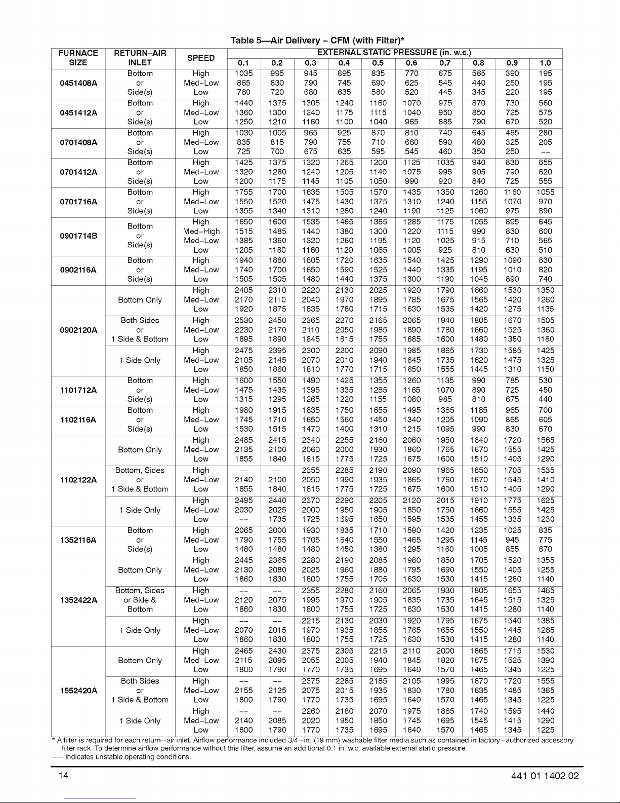
Table 5--Air Delivery - CFM (with Filter)*
FURNACE RETURN-AIR SPEED EXTERNAL STATIC PRESSURE (in, w,c,)
SIZE INLET 0,1 0,2 0,3 0,4 0,5 0,6 0,7 0,8 0,9 1,0
0451408A or Med-Low 865 830 790 745 690 625 545 440 250 195
0451412A or Med-Low 1360 1300 1240 1175 1115 1040 950 850 725 575
0701408A or Med-Low 835 815 790 755 710 660 590 480 325 205
0701412A or M ed-Low 1320 1280 1240 1205 1140 1075 995 905 790 620
0701716A or Med-Low 1550 1520 1475 1430 1375 1310 1240 1155 1070 970
0901714B or Med-High 1515 1485 1440 1380 1300 1220 1115 990 830 600
0902116A or Med-Low 1740 1700 1650 1590 1525 1440 1335 1195 1010 820
0902120A or M ed-Low 2230 2170 2110 2050 1985 1890 1780 1660 1525 1360
1101712A or Med-Low 1475 1435 1395 1335 1285 1185 1070 890 725 450
1102116A or Med-Low 1745 1710 1650 1560 1450 1340 1205 1090 865 605
1102122A or Med-Low 2140 2100 2050 1990 1935 1865 1760 1670 1545 14t0
1352116A or Med-Low 1790 1755 1705 1640 1550 1465 1295 1145 945 775
1352422A or Side & Med-Low 2120 2075 1995 1970 1905 1835 1735 1645 1515 1325
1552420A or Med-Low 2155 2125 2075 2015 1935 1830 1780 1635 1485 1365
* A filter is required for each return-air inlet.Airflow performance included 3/_-in, (19mm) washable filter media such as contained infactory-authorized accessory
filter rack. Todetermine airflow performance without this filter,assume an additional 0.1 in. w.c. available external static pressure.
-- Indicates unstable operating conditions.
Bottom High 1035 995 945 895 835 770 675 565 390 195
Side(s) Low 760 720 680 635 580 520 445 345 220 195
Bottom High 1440 1375 1305 1240 1160 1070 975 870 730 560
Side(s) Low 1250 1210 1160 1100 1040 965 885 790 670 520
Bottom High 1030 1005 965 925 870 810 740 645 465 280
Side(s) Low 725 700 675 635 595 545 460 350 250 --
Bottom High 1425 1375 1320 1265 1200 1125 1035 940 830 655
Side (s) Low 1200 1175 1145 1105 1050 990 920 840 725 555
Bottom High 1755 1700 1635 1505 1570 1435 1350 1260 1160 1055
Side(s) Low 1355 1340 1310 1280 1240 1190 1125 1060 975 890
Bottom High 1650 1600 1535 1465 1385 1285 1175 1055 895 645
Side(s) Low 1205 1180 1160 1120 1065 1005 925 810 630 510
Bottom High 1940 1880 1805 1720 1635 1540 1425 1290 1090 830
Side(s) Low 1505 1505 1480 1440 1375 1300 1190 1045 890 740
Bottom Only M ed-Low 2170 2110 2040 1970 1895 1785 1675 1565 1420 1260
Both Sides High 2530 2450 2365 2270 2165 2065 1940 1805 1670 1505
1 Side & Bottom Low 1895 1890 1845 1815 1755 1685 1600 1480 1350 1180
1 Side Only Med-Low 2105 2145 2070 2010 1940 1845 1735 1620 1475 1325
Bottom High 1600 1550 1490 1425 1355 1260 1135 990 785 530
Side(s) Low 1315 1295 1265 1220 1155 1080 985 810 675 440
Bottom High 1980 1915 1835 1750 1655 1495 1365 1185 965 700
Side(s) Low 1530 1515 1470 1400 1310 1215 1095 990 830 670
Bottom Only Med-Low 2135 2100 2060 2000 1930 1860 1765 1670 1555 1425
Bottom, Sides High .... 2355 2285 2190 2090 1965 1850 1705 1535
1 Side & Bottom Low 1855 1840 1815 1775 1725 1675 1600 1510 1405 1290
1 Side Only M ed-Low 2030 2025 2000 1950 1905 1850 1750 1660 1555 1425
Bottom High 2065 2000 1930 1835 1710 1590 1420 1235 1025 835
Side (s) Low 1480 1480 1480 1450 1380 1295 1160 1005 855 670
Bottom Only M ed- Low 2130 2080 2025 1960 1880 1795 1690 1550 1405 1255
Bottom, Sides High .... 2355 2280 2160 2065 1930 1805 1655 1465
Bottom Low 1860 1830 1800 1755 1725 1630 1530 14t5 1280 1140
1 Side Only M ed-Low 2070 2015 1970 1935 1855 1765 1655 1550 1445 1265
Bottom Only M ed-Low 2115 2095 2055 2005 1940 1845 1820 1675 1525 1390
Both Sides High .... 2375 2285 2185 2105 1995 1870 1720 1555
1 Side & Bottom Low 1800 1790 1770 1735 1695 1640 1570 1465 1345 1225
1 Side Only Med-Low 2140 2085 2020 1950 1850 1745 1695 1545 14t5 1290
Med-Low 1385 1360 1320 1260 1195 1120 1025 915 710 565
High 2405 2310 2220 2130 2025 1920 1790 1660 1530 1350
Low 1920 1875 1835 1780 1715 1630 1535 1420 1275 1135
High 2475 2395 2300 2200 2090 1985 1865 1730 1585 1425
Low 1850 1860 1810 1770 1715 1650 1555 1445 1310 1150
High 2485 24t 5 2340 2255 2160 2060 1950 1840 1720 1565
Low 1855 1840 1815 1775 1725 1675 1600 1510 1405 1290
High 2495 2440 2370 2290 2205 2120 2015 1910 1775 1625
Low -- 1735 1725 1695 1650 1595 1535 1455 1335 1230
High 2445 2365 2280 2190 2085 1980 1850 1705 1520 1355
Low 1860 1830 1800 1755 1705 1630 1530 14t5 1280 1140
High .... 2215 2130 2030 1920 1795 1675 1540 1385
Low 1860 1830 1800 1755 1725 1630 1530 14t5 1280 1140
High 2465 2430 2375 2305 2215 2110 2000 1865 1715 1530
Low 1800 1790 1770 1735 1695 1640 1570 1465 1345 1225
High .... 2260 2180 2070 1975 1865 1740 1595 1440
Low 1800 1790 1770 1735 1695 1640 1570 1465 1345 1225
14 441 01 1402 02
Page 15
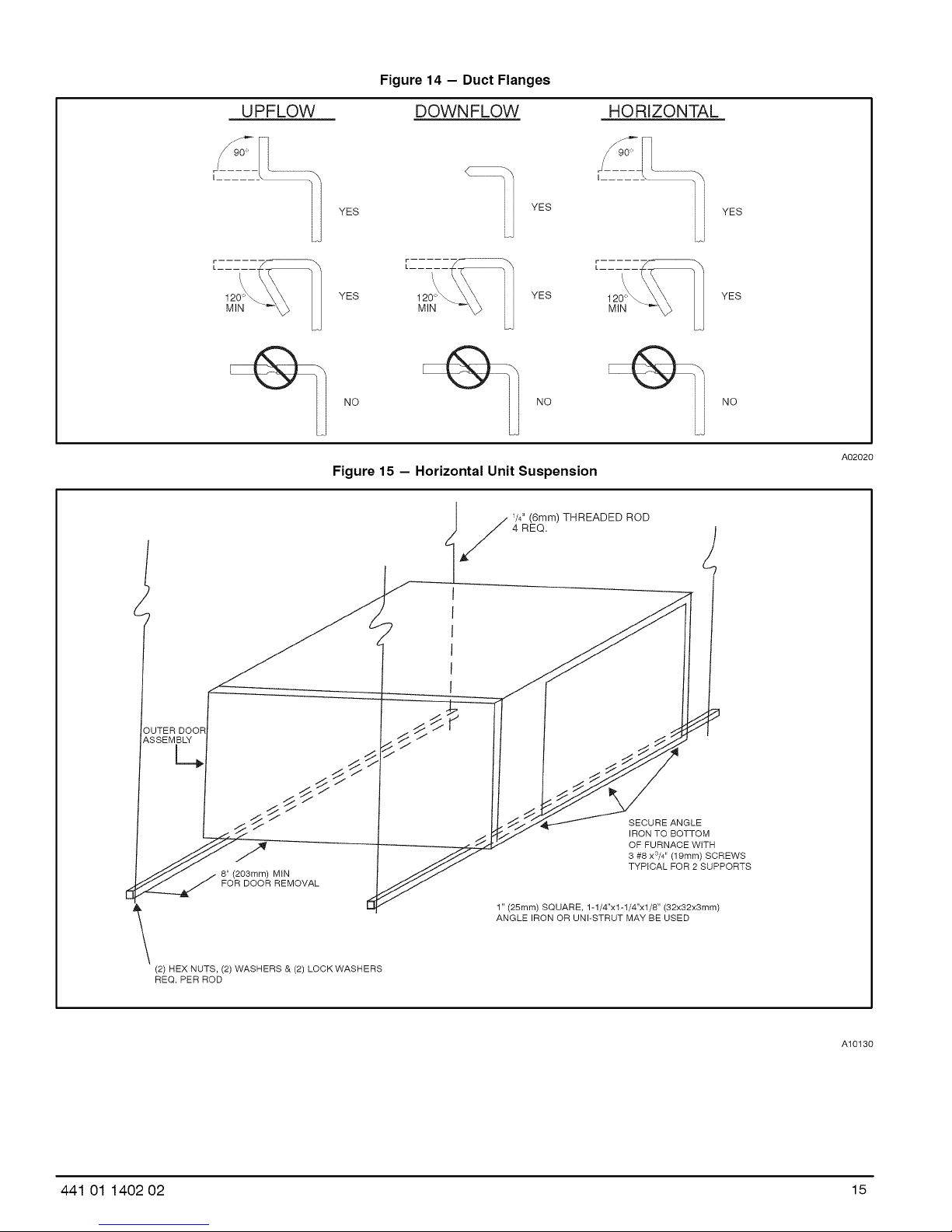
Figure 14 - Duct Flanges
UPFLOW
YES
/ t\ /\
120'_ YES 120°_ YES 120°_
MIN MIN MIN
NO NO NO
DOWNFLOW HORIZONTAL
I ......
YES
Figure 15 - Horizontal Unit Suspension
4 REQ,
/ /4" (6mm) THREADED ROD
YES
YES
A02020
/
OUTER DOOR
ASSEMBLY
c.
8" (203mm) MtN
FOR DOOR REMOVAL
(2) HEX NUTS, (2) WASHERS & (2) LOCK WASHERS
REQ. PER ROD
SECURE ANGLE
IRON TO BOTTOM
OF FURNACE WITH
3 #8 x3/4'' (19mm) SCREWS
TYPICAL FOR 2 SUPPORTS
1" (25ram) SQUARE, 1-1/4"x1-1/4"x1/8" (32x32x3mm)
ANGLE IRON OR UNI-STRUT MAY BE USED
A10130
441 01 1402 02 15
Page 16

Figure 16 - Horizontal Suspension with Straps
22 GAUGE GALVANIZED
STRAPS TYPICAL
FOR 4 STRAPS
/OPENING
AIR
OUTER DOOR
ASSEMBLY
[ //
7
J
J
J
J
J
J
J
J
J
J
Figure 17 - Typical Attic Installation
LINE CONTACT ONLY PERMISSIBLE BETWEEN
LINES FORMED BY INTERSECTIONS OF
THE TOP AND TWO SIDES OF THE FURNACE
JACKET AND BUILDING JOISTS,
STUDS, OR FRAMING.
I
ENTRY
METHOD 2
USE (4) #8 x 3/4 (19 mm) SHEET
METAL SCREWS FOR EACH
STRAR THE STRAPS
SHOULD BE VERTICAL
AGAINST THE FURNACE
FROM THE FURNACE
SIDES AND NOT PULL AWAY
SIDES.
BACK OF
FURNACE
METHOD 1
FOLD ALL STRAPS UNDER
FURNACE AND SECURE WTH
(4) #8 x 3/4 (t9 mm) SHEET METAL SCREWS
(2 SCREWS IN SiDE AND 2 SCREWS
iN BOTTOM).
TYPE-B
VENT
A10131
173/4" (451 mm)OVERALL
43/4" (121mm) UNDER DOOR
1" (25mm) UNDER FURNACE
EXTEND OUT 12" (305mm)
FROM FACE OF DOOR
EQUIPMENT MANUAL
SHUT-OFF GAS VALVE
SEDIMEN1
TRAP
16 441 01 1402 02
UNWON
i
30-IN. (762mm)
MIN WORK AREA *WHEN USED WITH
SINGLE WALL VENT
CONNECTIONS
A10164
Page 17

Figure 18 - Upflow Return Air Configurations and Restrictions
i ¸_
@
RETURN i
AIR
RETURN
AIR
UPFLOW RETURN AiR CONFiGURATiONS AND RESTRICTIONS
AIR _!_ RESTRICTIONS
RETURN T UPFL©W
RETURN AIR
AIR FLOW MODELS RETURN AIR RETURN AIR RETURN AIR RETURN AIR |
5 TONS AND YES YES YES YES |
GREATER *
ALL OTHER MODELS YES YES YES YES
• 2000 CFM AND GREATER AT .6 ESP HI COOLING SPEED
RETURN
AiR
CONNECTION 1 CONNECTION 2 CONNECTION 3 COMBINATIONS
ONLY ONLY ONLY OF 1,2, AND 3
Figure 19 - Downflow Return Air Configurations and Restrictions
_1_ RETURN
AIR
!
]
t
/
AIR
RETURN i
• NOTE: RESTRICTION SAME FOR
HORIZONAL LEFT
DOWNFLOWRETURNAJRCONRGURATIONSANDRESTRICq]ONS
AIR FLOW MODELS RETURN AIR RETURN AIR RETURN AIR RETURN AIR
5 TONS AND YES NO NO NO
GREATER *
ALL OTHER MODELS YES NO NO NO
• 2000 CFM AND GREATER AT .6 ESP HI COOLING SPEED
CONNECTION 1 CONNECTION 2 CONNECTION 3 COMBINATIONS
ONLY ONLY ONLY OF 1, 2, AND 3
Figure 20 - Horizontal Return Air Configurations and Restrictions
RETURN
........................(/ ........................
,@_ SIDERETURN AIR
_ NOTPERMI_ED FOR
066,060,-22-2O
AIR FLOWMODELS
AIR
II
II
II
II
I'\ /_lt_ _ SIDE RETURN AIR
, / _M NOT PERM _ED FOR
/" 066,060, _2_0
AIR FLOW MODELS
AaR RESTRICTIONS
i RETURN RETURNAIR
,r3_
_ HORIZONTAL RETURN AIR CONFIGURATIONS AND RESTRICTIONS
HORIZONAL
AiR FLOW MODELS RETURN AiR RETURN AIR RETURN AiR RETURN AiR
5 TONS AND YES NO NO NO
GREATER *
ALL OTHER MODELS YES YES YES YES
• 2000 CFM AND GREATER AT .6 ESP HI COOLING SPEED
CONNECTmON 1 CONNECTION 2 CONNECTmON 3 COMBJNATmONS
ONLY ONLY ONLY OF 1,2, AND 3
441 01 1402 02 17
Page 18

Upflow and Horizontal Furnaces
Connect supply-air duct to flanges on furnace supply-air
outlet. Bend flange upward to 90 ° with wide duct pliers. (See
Figure 14) The supply-air duct must be connected to ONLY
the furnace supply-outlet-air duct flanges or air conditioning
coil casing (when used). DO NOT cut main furnace casing
side to attach supply air duct, humidifier, or other accessories.
All accessories MUST be connected to duct external to
furnace main casing.
NOTE: For horizontal applications, the top-most flange may
be bent past 90 ° to allow the evaporator coil to hang on the
flange temporarily while the remaining attachment and
sealing of the coil are performed.
Downflow Furnaces
Connect supply-air duct to supply-air outlet on furnace. Bend
flange inward past 90 ° with wide duct pliers. (See Figure 14)
The supply-air duct must be connected to ONLY the furnace
supply-outlet or air conditioning coil casing (when used).
When installed on combustible material, supply-air duct must
be connected to ONLY the accessory subbase or a factory
approved air conditioning coil casing. DO NOT cut main
furnace casing to attach supply side air duct, humidifier, or
other accessories. All accessories MUST be connected to
duct external to furnace casing.
FIRE HAZARD
A failure to follow this warning could result in
personal injury, or death and/or property damage.
Never connect return-air ducts to the back of the
furnace. Follow instructions below.
Return Air Connections
Downflow Furnaces
The return-air duct must be connected to return-air opening
(bottom inlet) as shown in Figure 19. DO NOT cut into casing
sides (left or right). Side opening is permitted for only upflow
and most horizontal furnaces. (See Figure 19) Bypass
humidifier connections should be made at ductwork or coil
casing sides exterior to furnace.
Upflow and Horizontal Furnaces
The return-air duct must be connected to bottom, sides (left
or right), or a combination of bottom and side(s) of main
furnace casing as shown in Figure 18 and Figure 20. Bypass
humidifier may be attached into unused return air side of the
furnace casing. (See Figure 18 and Figure 20)
Not all horizontal furnaces are approved for side return air
connections. (See Figure 20)
GAS PIPING
FIRE OR EXPLOSION HAZARD
Failure to follow this warning could result in personal
injury, death, and/or property damage.
Never purge a gas line into a combustion chamber.
Never test for gas leaks with an open flame. Use a
commercially available soap solution made
specifically for the detection of leaks to check all
connections.
FIRE OR EXPLOSION HAZARD
Failure to follow this warning could result in personal
injury, death, and/or property damage.
Use proper length of pipe to avoid stress on gas
control manifold and a gas leak.
Gas piping must be installed in accordance with national and
local codes. Refer to current edition of NFGC.
Installations must be made in accordance with all authorities
having jurisdiction. If possible, the gas supply line should be a
separate line running directly from meter to furnace.
NOTE: In the state of Massachusetts:
1. Gas supply connections MUST be performed by a li-
censed plumber or gas fitter.
2. When flexible connectors are used, the maximum
length shall not exceed 36 inches (915 mm).
3. When lever handle type manual equipment shutoff
valves are used, they shall be T-handle valves.
4. The use of copper tubing for gas piping is NOT ap-
proved by the state of Massachusetts.
Refer to Table 6 for recommended gas pipe sizing. Risers
must be used to connect to furnace and to meter. Support all
gas piping with appropriate straps, hangers, etc. Use a
minimum of 1 hanger every 6 ft. (1.8 M) Joint compound (pipe
dope) should be applied sparingly and only to male threads of
joints. Pipe dope must be resistant to the action of propane
gas.
Table 6--Maximum Capacity of Pipe
NOMINAL
IRON PIPE
SIZE
IN. (MM)
1/2 (12,7)
3/4 (19.0)
1(25.4)
1-1/4 (31.8)
1-1/2 (38.1)
* Cubic ft. of natural gas per hr for gas pressures of 0.5 psig (14-in. w.c,) or
less and a pressure drop of 0.5-in. w,c. (based on a 0.60 specific gravity
gas). Ref: Table 6 and ANSI Z223-2009/NFPA 54-2009.
INTERNAL LENGTH OF PIPE - FT (M)
DIA.
'N. (MM) 110/ 1620/ 1930/ 11401/ 115502/
0.622 (158) 175 120 97 82 73
0.824 (20.9) 360 250 200 170 151
1.049 (26.6) 680 465 375 320 285
1.380 (35.0) 1400 950 770 660 580
1.610 (40.9) 2100 1460 1180 990 900
FIRE OR EXPLOSION HAZARD
Failure to follow this warning could result in personal
injury, death, and/or property damage.
If local codes allow the use of a flexible gas appliance
connector, always use a new listed connector. Do not
use a connector which has previously served another
gas appliance. Black iron pipe shall be installed at the
furnace gas control valve and extend a minimum of 2
in. (51 mm) outside the furnace.
18 441 01 1402 02
Page 19

FURNACE OVERHEAT HAZARD
Failure to follow this caution may result in unit
component damage.
Connect gas pipe to gas valve using a backup
wrench to avoid damaging gas controls and burner
misatiqnment.
An accessible manual equipment shutoff valve MUST be
installed external to furnace casing and within 6 ft. (1.8 M) of
furnace. A 1/8-in. (3 mm) NPT plugged tapping, accessible
for test gauge connection, MUST be installed immediately
upstream of gas supply connection to furnace and
downstream of manual equipment shutoff valve.
NOTE: The furnace gas valve inlet pressure tap connection
is suitable to use as test gauge connection providing test
pressure DOES NOT exceed maximum 0.5 psig (14-in. w.c.)
stated on gas control valve. (See Figure 41)
Figure 21 - Burner and Manifold
TOP VIEW OF BURNER AND MANIFOLD ASSEMBLY
Piping should be pressure and leak tested in accordance with
NFGC, local, and national plumbing and gas codes before
the furnace has been connected. After all connections have
been made, purge lines and check for leakage at furnace
prior to operating furnace.
If pressure exceeds 0.5 psig (14-in. w.c.), gas supply pipe
must be disconnected from furnace and capped before and
during supply pipe pressure test. If test pressure is equal to or
less than 0.5 psig (14-in. w.c.), turn off electric shutoff switch
located on furnace gas control valve and accessible manual
equipment shutoff valve before and during supply pipe
pressure test. After all connections have been made, purge
lines and check for leakage at furnace prior to operating
furnace.
Figure 23 - Relocating J-Box
FACTORY
INSTALLED
LOCATION
ALTERNATE
FIELD
LOCATION
2" (51 ram)Nipple
Street
t-Gas Valve
Figure 22 - Typical Gas Pipe Arrangement
GAS--
SUPPLY j'"_
MANUALJ II
SHUTOFF _ _
VALVE
(REQUIRED)_ "1_ }_
SEDIMENT-- /
TRAP /
UNION.-.J
Supply
A08551
Figure 24 - Field-Supplied Electrical Box on Furnace
Casing
O
A02035
Some installations require gas entry on right side of furnace
(as viewed in upflow.) (See Figure 21)
Install a sediment trap in riser leading to furnace as shown in
Figure 22. Connect a capped nipple into lower end of tee.
Capped nipple should extend below level of furnace gas
controls. Place a ground joint union between furnace gas
control valve and exterior manual equipment gas shutoff
valve. A 1/8-in. (3 mm) NPT plugged tapping, accessible for
test gauge connection, MUST be installed immediately
upstream of gas supply connection to furnace and
downstream of manual equipment shutoff valve.
441 01 1402 02 19
The gas supply pressure shall be within the maximum and
minimum inlet supply pressures marked on the rating plate
with the furnace burners ON and OFF.
Page 20

ELECTRICAL CONNECTIONS
ELECTRICAL SHOCK HAZARD
Failure to follow this warning could result in personal
injury or death.
Blower access panel door switch opens 115-v power
to control. No component operation can occur. Do not
bypass or close switch with panel removed.
See Figure 26 for field wiring diagram showing typical field
115-v wiring. Check all factory and field electrical
connections for tightness.
ELECTRICAL SHOCK AND FIRE HAZARD
Failure to follow this warning could result in personal
injury, death, or property damage.
The cabinet MUST have an uninterrupted or
unbroken ground according to NEC ANSI/NFPA
70-2008 or local codes to minimize personal injury if
an electrical fault should occur. This may consist of
electrical wire, conduit approved for electrical ground
or a listed, grounded power cord (where permitted
by local code) when installed in accordance with
existing electrical codes. Refer to the power cord
manufacturer's ratings for proper wire gauge. Do not
use gas piping as an electrical ground.
FURNACE MAY NOT OPERATE
Failure to follow this caution may result in intermittent
furnace operation.
Furnace control must be grounded for proper
operation or else control will lock out. Control must
remain grounded through green/yellow wire routed to
gas valve and manifold bracket screw.
115-V WIRING
Verify that the voltage, frequency, and phase correspond to
that specified on unit rating plate. Also, check to be sure that
service provided by utility is sufficient to handle load imposed
by this equipment. Refer to rating plate or Table 7 for
equipment electrical specifications.
Make all electrical connections in accordance with National
Electrical Code (NEC) ANSI/NFPA 70-2008 and any local
codes or ordinances that might apply.
NOTE: Proper polarity must be maintained for 115-v wiring.
If polarity is incorrect, control LED status indicator light will
flash a status code 10 and furnace wilt NOT operate.
J-BOX RELOCATION
NOTE: If factory location of J-Box is acceptable, go to next
section (ELECTRICAL CONNECTION TO J-BOX).
NOTE: On 14-in. (356 mm) wide casing models, the J-Box
shall not be relocated to other side of furnace casing when
the vent pipe is routed within the casing.
1. Remove and save two screws holding J-Box. (See
Figure 23)
NOTE: The J-Box cover need not be removed from the
J-Box in order to move the J-Box. Do NOT remove green
ground screw inside J-Box. The ground screw is not
threaded into the casing flange and can be lifted out of the
clearance hole in casing while swinging the front edge of the
J-Box outboard of the casing.
2. Cut wire tie on loop in furnace wires attached to J-box.
3. Move J-Box to desired location.
4. Fasten J-Box to casing with two screws removed in
Step 1.
5. Route J-Box wires within furnace away from sharp
edges, rotating parts and hot surfaces.
ELECTRICAL CONNECTION TO J-BOX
Field-Supplied Electrical Box on Furnace J-Box Bracket See
Figure 24.
1. Remove cover from furnace J-Box.
2. Attach electrical box to furnace J-Box bracket with at
least two field-supplied screws through holes in elec-
trical box into holes in bracket. Use blunt-nose screws
that will not pierce wire insulation.
3. Route furnace power wires through holes in electrical
box and J-Box bracket, and make field-wire connec-
tions in electrical box. Use best practices (NEC in U.S.)
for wire bushings, strain relief, etc.
4. Route and secure field ground wire to green ground
screw on J-Box bracket.
5. Connect line voltage leads as shown in Figure 26.
6. Reinstall cover to J-Box. Do not pinch wires between
cover and bracket. Electrical Box on Furnace Casing
Side See Figure 24.
FIRE OR ELECTRICAL SHOCK HAZARD
Failure to follow this warning could result in personal
injury, death, or property damage.
If field-supplied manual disconnect switch is to be
mounted on furnace casing side, select a location
where a drill or fastener cannot damage electrical or
gas components.
FIRE HAZARD
Failure to follow this warning could result in personal
injury, death, or property damage.
Do not connect aluminum wire between disconnect
switch and furnace. Use only copper wire.
Use a separate, fused branch electrical circuit with a properly
sized fuse or circuit breaker for this furnace. See Table 7 for
wire size and fuse specifications. A readily accessible means
of electrical disconnect must be located within sight of the
furnace.
20 441 01 1402 02
1. Select and remove a hole knockout in the caslng
where the electrical box is to be installed.
NOTE: Check that duct on side of furnace will not interfere
with installed electrical box.
2. Remove the desired electrical box hole knockout and
position the hole in the electrical box over the hole in
the furnace casing.
3. Fasten the electrical box to casing by driving two field
supplied screws from inside electrical box into casing
steel.
Page 21

4.RemoveandsavetwoscrewsholdingJ-Box.(See
Figure23)
5.Pullfurnacepowerwiresoutof1/2-in.(12mm)diamet-
erholeinJ-Box.Donotloosenwiresfromstrain-relief
wire-tieonoutsideofJ-Box.
6.Routefurnacepowerwiresthroughholesincasingand
electricalboxandintoelectricalbox.
7.Pullfieldpowerwiresintoelectricalbox.
8.RemovecoverfromfurnaceJ-Box.
9.Routefieldgroundwirethroughholesinelectricalbox
andcasing,andintofurnaceJ-Box.
10.ReattachfurnaceJ-Boxtofurnacecasingwithscrews
removedinStep4.
11.SecurefieldgroundwiretoJ-Boxgreengroundscrew.
Table 7--Electrical Data
VOLTS-
FURNACE
SIZE
0451408A
0451412A
0701408A
0701412A
0701716A
0901714B
0902116A
0902120A
1101712A
1102116A
1102122A
1352116A
1352422A
1552420A
Permissible limits of the voltage range at which the unit operates satisfactorily.
# Unit ampacity = 125 percent of largest operating component's full load amps plus 100 percent of all other potential operating components'
load amps.
Time-delay type is recommended.
Length shown is as measured 1 way along wire path between unit and service panel for maximum 2 percent voltage drop.
HERTZ-
PHASE
115-60-1
115-60-1
115-60-1
115-60-1
115-60-1
115-60-1
115-60-1
115-60-1
115-60-1
115-60-1
115-60-1
115-60-1
115-60-1
115-60-1
12. Complete electrical box wiring and installation. Connect
line voltage leads as shown in Figure 26. Use best
practices (NEC) for wire bushings, strain relief, etc.
13. Reinstall cover to J-Box. Do not pinch wires between
cover and bracket.
POWER CORD INSTALLATION IN FURNACE J-BOX
NOTE: Power cords must be able to handle the electrical
requirements listed in Table 7. Refer to power cord
manufacturer's listings.
1. Remove cover from J-Box.
2. Route listed power cord through 7/8-in. (22 mm) dia-
OPERATING
VOLTAGE RANGE
Maximum* Minimum*
127 104
127 104
127 104
127 104
127 104
127 104
127 104
127 104
127 104
127 104
127 104
127 104
127 104
127 104
MAXIMUM
UNIT
AMPS
5.2
7.2
5.1
7.2
9.5
8.2
10.0
14.1
8.6
10.2
15.1
10.5
14.5
15.4
UNIT
AMPAClTY
#
7.26
9.79
7.14
9.72
12.60
10.83
13.09
18.20
11.27
13.34
19.42
13.63
18.72
19.83
BX CABLE INSTALLATION IN FURNACE J-BOX
1. Remove cover from J-Box.
2. Route BX cable into 7/8-inch (22 mm) diameter hole in
J-Box.
3. Secure BX cable to J-Box bracket with connectors ap-
proved for the type of cable used.
4. Secure field ground wire to green ground screw on
J-Box bracket.
5. Connect line voltage leads as shown in Figure 26.
6. Reinstall cover to J-Box. Do not pinch wires between
cover and bracket.
MAXIMUM
WIRE
LENGTH
FT. (M)$
49 (15)
37 (12)
51 (16)
38 (12)
29 (9)
34 (10)
28 (9)
31 (9)
32 (10)
27 (9)
29 (8)
27 (8)
30 (9)
29 (9)
MAXIMUM
FUSE OR
CKT BKR
AMPSt
meter hole in J-Box.
3. Secure power cord to J-Box bracket with a strain relief
bushing or a connector approved for the type of cord
used.
4. Secure field ground wire to green ground screw on
J-Box bracket.
5. Connect line voltage leads as shown in Figure 26.
6. Reinstall cover to J-Box. Do not pinch wires between
cover and bracket.
MINIMUM
GAUGE
15
15
15
15
15
15
15
20
15
15
2O
15
2O
2O
(EAC, humidifier, etc.) full
WIRE
14
14
14
14
14
14
14
12
14
14
12
14
12
12
441 01 1402 02 21
Page 22

Figure 25 - Furnace Control
HEAT TWINNING AND/OR
J2 JUMPER
24-V THERMOSTAT
TERMINALS
3-AMP FUSE
LED OPERATION &
DIAGNOSTIC LIGHT
115-VAC (L2) NEUTRAL
CONNECTIONS
BLOWER SPEED s _ ........... 115VA! EAC_ ...... ,M ,ND_HS,
SELECT'ON TER_ !O_N_AG:ET, O N iA! V_ACRx1M._A' 1THI_E_M/!_cFAIE R p_-HoOT (tNUDRFcACE/G_ (H S ,) & , N D U C ER
OFF-DELAY COMPONENT TEST
TERMINAL
TRANSFORMER 24-MAC
CONNECTIONS
HARNESS CONNECTOR
owvoT
Figure 26 - Heating and Cooling Application Wiring Diagram with Single Stage Thermostat
NOTE 2
FIVEWIRE _ l(_ (_ (_
THREE-WIRE_ _.---'_---_-
HEATING-ONLY _'_ _f -T- _-
BLOWER DOOR SWITCH"-_ "__
115-V FIELD- AUXILIARY O _c_ __ -,
SUPPLIED
DISCONNECT _ NOTE 1
J-BOX L ('_ ....... _,
24-V
TERMINA
BLOCK
FURNACE
NOTES:I.
24-V WIRING
Make field 24-v connections at the 24-v terminal strip. (See
Figure 25) Connect terminal Y as shown in Figure 26 for
proper cooling operation. Use only AWG No. 18,
color-coded, copper thermostat wire.
The 24-v circuit contains an automotive-type, 3-amp. fuse
located on the control. Any direct shorts during installation,
service, or maintenance could cause this fuse to blow. If fuse
replacement is required, use ONLY a 3-amp. fuse of identical
size.
- - - FIELD24-VWIRING
= = = FIELD 115-, 208/230-, 460-V WIRING
-- FACTORY 24-V WIRING
FACTORY 115-V WiRiNG
(_ (_ ] THERMOSTAT
TERMINALS
m
, ?i_ii!iiiii!iiiiiiii_i}_
i_iiiiiiiiiiiiiiii_!_
FIELD-SUPPLIED
DISCONNECT
=
460-V
THREE
1208/230- OR
PHASE
SINGLE
PHASE
} 208/230-V
=4 CONDENSING
L TWO UNIT
WIRE
Connect Y-terminal in furnace as shown for proper blower operation.
2.
Some thermostats require a "C" terminal connection as shown.
3.
If any of the original wire, as supplied, must be replaced, use
same type or equivalent wire.
ACCESSORIES
1. Electronic Air Cleaner (EAC):
Connect an accessory Electronic Air Cleaner (if used)
using 1/4-in female quick connect terminals to the two
male 1/4-in quick-connect terminals on the control
board marked EAC 1 AMP and NEUTRAL. The termin-
als are rated for 115 VAC, 1.0 amps maximum and are
energized during blower motor operation. (See
Figure 24)
22 441 01 1402 02
Page 23

2.Humidifier(HUM24VACandHUM)
a. HUM24VAC:Connectanaccessory24
VAC,0.5ampmaximumhumidifier(ifused)tothe
1/4-inmalequick-connectHUM24VACterminal
andCscrewterminalonthecontrolboardthermo-
statstrip.TheHUM24VACterminalisenergized
whenthereisacallforheat(W)andthepressure
switch(PRS)closes.(SeeFigure24andFigure48).
b. HUM:Connectanaccessory115VAC(EAC
andHUMare1ampmaximumcombined)humidifier
(ifused)tothe]A-inchmalequickconnectHUM
terminalandNEUTRAL]A-inchquickconnect.The
HUMterminalisenergizedwhentheinducermotor
isenergized(IDR).(SeeFigure24andFigure48).
NOTE:Afield-supplied,115-vcontrolledrelayconnectedto
EACterminalsmaybe addedif humidifieroperationis
desiredduringbloweroperation.
NOTE: DONOTconnectfurnacecontrolHUM24VAC
terminalto H (humidifier)terminalon humiditysensing
thermostat,or similardevice.See humiditysensing
thermostat,thermostat,or controllermanufacturer's
instructionsforproperconnection.
VENTING
The furnace shall be connected to a listed factory built
chimney or vent, or a clay-tile lined masonry or concrete
chimney. Venting into an unlined masonry chimney or
concrete chimney is prohibited.
When an existing Category I furnace is removed or replaced,
the original venting system may no longer be sized to
properly vent the attached appliances. An improperly sized
Category I venting system could cause the formation of
condensate in the furnace and vent, leakage of condensate
and combustion products, and spillage of combustion
products into the living space.
Vent system or vent connectors may need to be resized. Vent
systems or vent connectors, must be sized to approach
minimum size as determined using appropriate table found in
the NFGC.
GENERAL VENTING REQUIREMENTS
Follow all safety codes for proper vent sizing and installation
requirements, including local building codes, the National
Fuel Gas Code ANSI Z223.1-2009/NFPA 54-2009 (NFGC),
Parts 12 and 13, local building codes, and furnace and vent
manufacturers' instructions.
CARBON MONOXIDE POISONING HAZARD
Failure to follow the steps outlined below for each appliance
connected to the venting system being placed into operation
could result in carbon monoxide poisoning or death.
The following steps shall be followed for each appliance
connected to the venting system being placed into operation,
while all other appliances connected to the venting system
are not in operation:
1. Seal any unused openings in venting system.
2. Inspect the venting system for proper size and horizontal
pitch, as required in the National Fuel Gas Code, ANSI
Z223.1/NFPA 54 and these instructions. Determine that there
is no blockage or restriction, leakage, corrosion and other
deficiencies, which could cause an unsafe condition.
3. As far as practical, close all building doors and windows
and all doors between the space in which the appliance(s)
connected to the venting system are located and other
spaces of the building.
4. Close fireplace dampers.
5. Turn on clothes dryers and any appliance not connected to
the venting system. Turn on any exhaust fans, such as range
hoods and bathroom exhausts, so they are operating at
maximum speed. Do not operate a summer exhaust fan.
6. Follow the lighting instructions. Place the appliance being
inspected into operation. Adjust the thermostat so appliance
is operating continuously.
7. Test for spillage from draft hood equipped appliances at the
draft hood relief opening after 5 minutes of main burner
operation. Use the flame of a match or candle.
8. If improper venting is observed during any of the above
tests, the venting system must be corrected in accordance
with the National Fuel Gas Code, ANSI Z223.1/NFPA 54.
9. After it has been determined that each appliance
connected to the venting system properly vents when tested
as outlined above, return doors, windows, exhaust fans,
fireplace dampers and any other gas-fired burning appliance
to their previous conditions of use.
These furnaces are design-certified as Category I furnaces in
accordance with ANSI Z21.47-2009/CSA 2.3-2009 and
operate with a non-positive vent static pressure to minimize
the potential for vent gas leakage. Category I furnaces
operate with a flue loss not less than 17 percent to minimize
the potential for condensation in the venting system. These
furnaces are approved for common venting and multistory
venting with other fan assisted or draft hood equipped
appliances in accordance with the NFGC, the local building
codes, and furnace and vent manufacturers' instructions.
The following information and warning must be considered in
addition to the requirements defined in the NFGC.
441 01 1402 02 23
CARBON MONOXIDE POISONING HAZARD
Failure to follow this warning could result in personal injury
or death.
Do not bypass the draft safeguard switch, as an unsafe
condition cou d exist which must be corrected.
1. If a vent (common or dedicated) becomes blocked, the
furnace will be shut off by the draft safeguard switch
located on the vent elbow.
2. Do not connect this Category I furnace into a single-
wall dedicated or common vent. The dedicated or com-
mon vent is considered to be the vertical portion of the
vent system that terminates outdoors.
3. Vent connectors serving Category I furnaces shall not
be connected into any portion of a mechanical draft
system operating under positive pressure.
Page 24

4.Donotventthisappliancewithanysolidfuelburning
appliance.
5.CategoryIfurnacesmustbeventedverticallyornearly
verticallyunlessequippedwithalistedpowerventer.
6.Donotventthisapplianceintoanunlinedmasonry
chimney.RefertoChimneyInspectionChart.
MASONRY CHIMNEY REQUIREMENTS
NOTE: These furnaces are CSA design-certified for use in
exterior clay tile-lined masonry chimneys with a factory
accessory Chimney Adapter Kit. Refer to the furnace rating
plate for correct kit usage. The Chimney Adapter Kits are for
use with ONLY furnaces having a Chimney Adapter Kit
numbers marked on the furnace rating plate.
If a clay tile-lined masonry chimney is being used and it is
exposed to the outdoors below the roof line, relining might be
required. Chimneys shall conform to the Standard for
Chimneys, Fireplaces, Vents, and Solid Fuel Burning
Appliances ANSI/NFPA 211-2009 and must be in good
condition.
U.S.A.-Refer to NFPA 54/ANSI Z223.1-2009 Sections 13.1.8
and 13.2.20 of the NFGC or the authority having jurisdiction
to determine whether relining is required. If relining is
required, use a properly sized listed metal liner, Type-B vent,
or a listed alternative venting design.
NOTE: See the NFPA 54 / ANSI Z223.1-2009, 13.1.8 and
13.2.20 regarding alternative venting design and the
Exception, which cover installations such as the Chimney
Adapter Kits, which are listed for use with these furnaces.
The Chimney Adapter Kit is listed alternative venting system
for these furnaces. See the kit instructions for complete
details.
This furnace is permitted to be vented into a clay tile-lined
masonry chimney that is exposed to the outdoors below the
roof line, provided:
1. Vent connector is Type-B double-wall, and
2. This furnace is common vented with at least 1 draft
hood equipped appliance, and
3. The combined appliance input rating is less than the
maximum capacity given in Table 8, and
4. The input rating of each space heating appliance is
greater than the minimum input rating given in Table 9
for the local 99% Winter Design Temperature. Chim-
neys having internal areas greater than 38 in2 (24516
mm2) require furnace input ratings greater than the in-
put ratings of these furnaces. See footnote at bottom of
Table 9, and
5. The authority having jurisdiction approves.
If all of these conditions cannot be met, an alternative venting
design shall be used, such as the listed chimney adapter kit
with these furnaces, which are listed for use with the kit, a
listed chimney-lining system, or a Type-B common vent.
Inspections before the sale and at the time of installation will
determine the acceptability of the chimney or the need for
repair and/or (re)lining. Refer to the Chimney Inspection Chart
to perform a chimney inspection. If the inspection of a
previously used tile-lined chimney:
a. Shows signs of vent gas condensation, the chim-
ney should be relined in accordance with local
codes and the authority having jurisdiction. The
chimney should be relined with a listed metal liner,
Type-B vent, or a listed chimney adapter kit shall
be used to reduce condensation. If a condensate
drain is required by local code, refer to the NFPA 54
/ ANSI Z223.1-2009, Section 12.10 for additional
information on condensate drains.
b. Indicates the chimney exceeds the maximum per-
missible size in the tables, the chimney should be
rebuilt or relined to conform to the requirements of
the equipment being installed and the authority hav-
ing jurisdiction.
A chimney without a clay tile liner, which is otherwise in good
condition, shall be rebuilt to conform to ANSI/NFPA 211 or be
lined with a UL listed metal liner or UL listed Type-B vent.
Relining with a listed metal liner or Type-B vent is considered
to be a vent-in-a-chase.
If a metal liner or Type-B vent is used to line a chimney, no
other appliance shall be vented into the annular space
between the chimney and the metal liner.
24 441 01 1402 02
Page 25

Figure 27 - Chimney Inspection Chart
CHIMNEY INSPECTION CHART
For additional requirements refer to the National Fuel Gas Code NFPA 54/ANSI Z223.1 and ANSI/NFPA 211
Chimneys, Fireplaces, Vents, and Solid Fuel Burning Appliances
Crown
condition: Rebuild
Missing mortar crown.
or brick?
Is chimney
property lined with
clay tile liner?
Is Repair
liner and top liner or top seal
seal in good or reline chimney as
condition? necessary.
Yes Repair
in cleanout? Mortar
Mortar, tile, or tile
fuel oil residue? debris?
Clay
tile misalignment,
missing sections,
gaps?
No
Remove metal vent
or liner.
Yes
Reline
Part B of
instructionsfor
Remove mortar
and tile debris
Not Suitable
1
>
1
Condensate
Chimney
exposed to
outdoors below
roof line?
441 01 1402 02 25
lined with properly
sized, listed liner or
Yes
Ischimney
to bededicated to
a single
furnace?
adapter per
Install chimney I
instructions. _lot Suitable
Part Col
instructions for
application
Line chimney with property
sized, listed flexible metal
liner or Type-B vent per
NFGC Vent
Sizing Tables and liner or
vent manufacturer's
Installation instructions.
3uitable
_r
adapter per
1stall chimney I
instructions.
A10133
Page 26

APPLIANCE APPLICATION REQUIREMENTS
Appliance operation has a significant impact on the
performance of the venting system. If the appliances are
sized, installed, adjusted, and operated properly, the venting
system and/or the appliances should not suffer from
condensation and corrosion. The venting system and all
appliances shall be installed in accordance with applicable
listings, standards, and codes.
The furnace should be sized to provide 100 percent of the
design heating load requirement plus any margin that occurs
because of furnace model size capacity increments. Heating
load estimates can be made using approved methods
available from Air Conditioning Contractors of America
(Manual J); American Society of Heating, Refrigerating, and
Air-Conditioning Engineers; or other approved engineering
methods. Excessive oversizing of the furnace could cause
the furnace and/or vent to fail prematurely.
When a metal vent or metal liner is used, the vent must be in
good condition and be installed in accordance with the vent
manufacturer's instructions.
To prevent condensation in the furnace and vent system, the
following precautions must be observed:
1. The return-air temperature must be at least 60°F
(16°0) db except for brief periods of time during warm-
up from setback at no lower than 55°F (13°O) db or
during initial start-up from a standby condition.
2. Adjust the gas input rate per the installation instruc-
tions. Low gas input rate causes low vent gas temper-
atures, causing condensation and corrosion in the fur-
nace and/or venting system. Derating is permitted only
for altitudes above 2000 ft. (610 M).
3. Adjust the air temperature rise to the midpoint of the
rise range or slightly above. Low air temperature rise
can cause low vent gas temperature and potential for
condensation problems.
4. Set thermostat heat anticipator or cycle rate to reduce
short cycling.
Table 8_ EXTERIOR MASONRY CHIMNEY FAN + NAT
INSTALLATIONS WITH TYPE-B DOUBLE WALL VENT
CONNECTORS ©NFPA & AGA Combined Appliance
Maximum Input
Rating in Thousands of Btuh per Hour
INTERNALAREA OF CHIMNEY
VENT HEIGHT
FT, (i)
6 (1.8)
8(2.4)
10(3.0)
15(4.5)
20 (6.0)
30 (9.1)
12
(7741)
74
80
84
NR
NR
NR
SQ. IN. (SQ. MM)
19 28
(12258) (18064)
119 178
130 193
138 207
152 233
NR 250
NR NR
38
(24516)
257
279
299
334
368
404
Table 9--Minimum Allowable Input Rating of Space-Heat-
ing Appliance in Thousands of Btuh per Hour
INTERNAL AREA OF CHIMNEY
VENT HEIGHT
FT. (M) 12 19 28 38
(7741) (12258) 18064) (24516)
Local 99% Winter Design Temperature: 17 to 26 degrees F
6 0 55 99 141
8 52 74 111 154
10 NR 90 125 169
15 NR NR 167 212
20 NR NR 212 258
30 NR NR NR 362
Local 99% Winter Design Temperature: 5 to 16 degrees F*
6 NR 78 121 166
8 NR 94 135 182
10 NR 111 149 198
15 NR NR 193 247
20 NR NR NR 293
30 NR NR NR 377
Local 99% Winter Design Temperature: -10 to 4 degrees F*
6 NR NR 145 196
8 NR NR 159 213
10 NR NR 175 231
15 NR NR NR 283
20 NR NR NR 333
30 NR NR NR NR
Local 99% Winter Design Temperature: -11 °F (ld°C) or
Not recommended for any vent configuration.
*The 99.6% heating db temperatures found in the 1997 or 2001 ASHRAE
Fundamentals Handbook, Climatic Design Information chapter, Table 1A
(United States) and 2A (Canada) or the 2005 ASHRAE Fundamentals hand-
book, Climatic Design Information chapter, and the CD-ROM included with
the 2005 ASHRAE Fundamentals Handbook.
SQ, IN. (SQ, MM)
lower
Air for combustion must not be contaminated by halogen
compounds which include chlorides, fluorides, bromides, and
iodides. These compounds are found in many common home
products such as detergent, paint, glue, aerosol spray,
bleach, cleaning solvent, salt, and air freshener, and can
cause corrosion of furnaces and vents. Avoid using such
products in the combustion-air supply. Furnace use during
construction of the building could cause the furnace to be
exposed to halogen compounds, causing premature failure of
the furnace or venting system due to corrosion.
Vent dampers on any appliance connected to the common
vent can cause condensation and corrosion in the venting
system. Do not use vent dampers on appliances common
vented with this furnace.
ADDITIONAL VENTING REQUIREMENTS
A 4-in. (102 mm) round vent elbow is supplied with the
furnace. A 5-in. (127 mm) or 6-in. (152 mm) vent connector
may be required for some model furnaces. A field-supplied
4-in. (102 mm) to 5-in. (127 mm) or 4-in. (102 mm) to 6-in.
(152 mm) sheet metal increaser fitting is required when 5-in.
(127 mm) or 6-in. (152 mm) vent connector is used. See
Figure 28 - Figure 40 Venting Orientation for approved vent
configurations.
NOTE: Vent connector length for connector sizing starts at
furnace vent elbow. The 4-in. (102 mm) vent elbow is
shipped for upflow configuration and may be rotated for other
positions. Remove the 3 screws that secure vent elbow to
furnace, rotate furnace vent elbow to position desired,
reinstall screws. The factory-supplied vent elbow does NOT
count as part of the number of vent connector elbows.
26 441 01 1402 02
Page 27

Theventconnectorcanexitthecabinetof thefurnace
throughoneoffivelocations.
1.Attachthesinglewaltventconnectortothefurnace
ventelbow,andfastentheventconnectortothevent
elbowwithatleasttwofield-supplied,corrosion-resist-
ant,sheetmetalscrewslocated180°apart.
NOTE:Aflueextensionisrecommendedtoextendfromthe
furnaceelbowtooutsidethefurnacecasing.Ifflueextension
isused,fastentheflueextensiontotheventelbowwithat
leasttwofield-supplied,corrosion-resistant,sheetmetal
screwslocated180° apart.Fastentheventconnectortothe
flueextensionwithat leasttwofield-supplied,corrosion
resistantsheetmetalscrewslocated180°apart.
2.Ventthefurnacewiththeappropriateconnectoras
shownin Figure28- Figure40.
CUTHAZARD
Failure to follow this caution may result in personal
injury. Sheet metal parts may have sharp edges or
burrs.
Use care and wear appropriate protective clothing,
safety glasses and gloves when handling parts and
servicing furnaces.
3. Determine the correct location of the knockout to be re-
moved.
4. Use a hammer and screwdriver to strike a sharp blow
between the tie points and work the slug back and forth
until the slug breaks free.
BURN HAZARD
Failure to follow this caution may cause personal
injury.
Hot vent pipe is within reach of small children when
installed in downflow position. See the following
instruction.
An accessory Vent Guard Kit is REQUIRED for downflow
applications for use where the vent exits through the lower
portion of the furnace casing door. Refer to the Vent Guard Kit
Instructions for complete details.
The horizontal portion of the venting system shall slope
upwards not tess than 1/4-in. (6 mm) per linear ft. (21 mm/m)
from the furnace to the vent and shall be rigidly supported
every 5 ft. (1.5 M) or less with metal hangers or straps to
ensure there is no movement after installation.
SIDEWALL VENTING
This furnace is not approved for direct sidewall horizontal
venting.
Per section 12.4.3 of the NFPA 54 / ANSI Z223.1-2009, any
listed mechanical venter may be used, when approved by the
authority having jurisdiction.
Caution!! for the following applications, use the minimum
vertical vent heights as specified below.
For all other applications, follow exclusively the national fuel
gas code.
Table lO_Minimum Vent Heights
FURNACE ORIENTATION DIAMETER IN, VENT HEIGHT
Downflow Vent Elbow left, 132,000 5 (127) 12 (3.6)
Horizontal Left then up Figure 35 132,000
Horizontal Left Figure 36 132,000 5 (127) 7 (2.2)
Horizontal Left Figure 36 154,000 5 (127) 7 (2.2)
Downflow Vent elbow up then left
Downflow Vent elbow up, then right
4 in. (102 mm) inside casing or vent uard
** Including 4 in. (102 mm) vent section (s)
NOTE: All vent configurations must also meet National Fuel Gas Code (NFGC) venting requirements
NOTE: For all unlisted vent configurations, refer to National Fuel Gas Code (NFGC) venting requirements.
VENT FURNACE
ORIENTATION INPUT (BTUH/HR) (mm)* FT, (M)**
154,000
then up Figure 32 110,000 (3 ton only)
Vent Elbow right, 154,000 5 (127) 7 (2.2)
Vent Elbow up 154,000
Vent Elbow up
Figure 30 110,000 (3 ton only) 5 (127) 10 (3.0)
Figure 33 110,000 (3 ton only) 5 (127) 10 (3.0)
MINIMUM VENT MINIMUM VERTICAL
441 01 1402 02 27
Page 28

Figure 28 - Upflow Application-Vent Elbow Up Figure 30 - Downflow Application-Vent Elbow Up then
Left
SEE NOTES: 1,2,4,7,8,9
on the page following
these figures
SEE NOTES:1,2,3,4,5,7,8,9
A03208
Figure 29 -- Upflow Application-Vent Elbow Right
on the page following
these figures
Figure 31 -- Downflow Application-Vent Elbow Up
A03210
.j,
SEE NOTES: 1,2,3,4,7,8,9
on the pages following
these figures
A03209
SEE NOTES: 1,2,4,5,7,8,9
on the page following
these figures
A03211
28 441 01 1402 02
Page 29

Figure 32 - Downflow Application-Vent Elbow Left then
Up
k)
o
i
Figure 35 - Horizontal Left Application-Vent Elbow
Ric
SEE NOTES: 1,2,4,5,7,8,9 on the page
following these figures
A032t 4
Figure 36 -- Horizontal Left Application-Vent Elbow Up
SEE NOTES: 1,2,4,5,8,7,8,9,t0
on the page following these figures
A03207
Figure 33 -- Downflow Application-Vent Elbow Up then
Right
SEE NOTES:1,2,3,4,5,7,8,9
on the page following
these figures.
A032t 2
Fi_iure 34 -- Horizontal Left Application-Vent Elbow Left
. o.
/ _
,\/,
SEE NOTES: 1,2,4,5,7,8,9 on the page
following these figures
Figure 37 -- Horizontal Left Application-Vent Elbow
Right
11
S--,/
SEE NOTES: 1,2,4,5,7,8,9 on the page
following these figures
Figure 38 -- Horizontal Right Application-Vent Elbow
Right
A03215
A03216
SEE NOTES: 1,2,4,7,8,9 on the page
following these figures
441 01 1402 02 29
A03213
SEE NOTES: 1,2,4,7,8,9 on the page
following these figures
A03218
Page 30

Figure 39 - Horizontal Right Application-Vent Elbow
Left then Up
O
SEE NOTES: 1,2,4,5,7,8,9 on the page
following these figures
A03219
Figure 40 -- Horizontal Right Application-Vent Elbow
Left
. J
SEE NOTES: 1,2,4,5,7,8,9
START-UP, ADJUSTMENT, AND SAFETY
CHECK
Step 1 --General
FIRE HAZARD
Failure to follow this warning could result in personal
injury, death and/or property damage.
This furnace is equipped with manual reset limit
switches in the gas control area. The switches open
and shut off power to the gas valve if a flame rollout or
overheating condition occurs in the gas control area.
DO NOT bypass the switches. Correct inadequate
combustion air supply problem before resetting the
switches.
CUT HAZARD
Failure to follow this caution may result in personal
injury. Sheet metal parts may have sharp edges or
burrs.
Use care and wear appropriate protective clothing,
safety glasses, and gloves when handling parts and
servicing furnaces.
Notes for Figure 33 - Figure 40
1. Forcommon vent, vent connectorsizing and vent material,use
the NFGC.
2. Immediatelyincreaseto 5-in. (127 mm) or 6-in. (152mm) vent
connector outside furnace casing when 5-in. (127 mm) vent
connector is required, refer to Note1 above.
3. Sideoutlet vent for upflow anddownflow installationsmust use
Type B vent immediately after exitingthe furnace, exceptwhen
the DownflowVent Guard Kit,is usedin the downflow position
4. Type-B vent where required, refer to theNote 1above.
5. A 4-in. (102 mm) single-wall (26 ga. minimum) vent must be
used inside furnace casing and when the Downflow Vent
Guard Kit is used external to the furnace.
6. Accessory Downflow Vent Guard Kit is required in downflow
installationswith lowervent configuration.
7. Chimney Adapter Kit may be required for exterior masonry
chimney applications. Refer to Chimney Adapter Kitfor sizing
andcomplete applicationdetails.
8. Securevent connectorto furnace elbowwith (2)corrosion-res-
istantsheet metal screws, spaced approximately 180° apart.
9. Secureall othersingle wallvent connectorjoints with (3)corro-
sion resistant screwsspaced approximately 120° apart. Secure
Type-B vent connectors per vent connector manufacturer's re-
commendations.
A02068
1. Maintain 115-v wiring and ground. Improper polarity
will result in flashing a status code 10 and no furnace
operation.
2. Make thermostat wire connections at the 24-v terminal
block on the furnace control. Failure to make proper
connections will result in improper operation. (See
Figure 26)
3. Gas supply pressure to the furnace must be greater
than 4.5-in. w.c. (0.16 psig ) but not exceed 14-in. w.c.
(0.5 psig).
4. Check all manual-reset switches for continuity.
5. Install blower compartment door. Door must be in place
to operate furnace.
6. Replace outer door.
Step 2--Start-Up Procedures
FIRE AND EXPLOSION HAZARD
Failure to follow this warning could result in personal
injury, death and or property damage.
Never test for gas leaks with an open flame. Use a
commercially available soap solution made
specifically for the detection of leaks to check all
connections.
30 441 01 1402 02
1. Purge gas lines after all connections have been made.
2. Check gas lines for leaks.
Page 31

ELECTRICALSHOCKHAZARD
Failure to follow this warning could result in personal
injury, or death.
Blower access door switch opens 115-v power to
control. No component operation can occur unless
switch is closed. Caution must be taken when
manually closing this switch for service purposes.
3. To Begin Component Self-Test: Remove blower ac-
cess door. Disconnect the thermostat R lead from the
furnace control board. Manually close the blower door
switch. Short (jumper) the C terminal on control to the
TEST/TWIN 3/16-inch quick connect terminal on con-
trol until LED goes out (approximately 2 sec). Gas
valve and humidifier will not be turned on. (See
Figure 25)
NOTE: The furnace control allows all components, except
the gas valve, to be run for short period of time. This feature
helps diagnose a system problem in case of a component
failure. Component test feature will not operate if any
thermostat signal is present at the control.
Component test sequence is as follows:
Refer to service label attached to furnace or see Figure 44.
a. LED will display previous status code 4 times.
NOTE: If no previous code is present, go directly to b.
b. Inducer motor starts and continues to run until Step
f of component test sequence.
c. Hot surface igniter is energized for 15 sec., then off.
d. Blower motor operates on HEAT speed for 10 sec.
e. Blower motor operates on COOL speed for 10 sec.
f. Inducer motor stops.
g. Reconnect R lead to furnace control board, release
blower door switch and re-install blower door.
4. Operate furnace per instruction on door.
5. Verify furnace shut down by lowering thermostat setting
below room temperature.
6. Verify furnace restarts by raising thermostat setting
above room temperature.
Step 3--Adjustments
Table 11--Altitude Derate Multiplier for U.S.A.
ALTITUDE PERCENT DERATEMULTIPLIER
FT,(M) OF DERATE FACTOR*
0-2000
(0-610)
2001-3000
(610-914)
3001-4000
(914-1219)
4001-5000
(1219-1524)
5001-6000
1524-1829)
6001-7000
(1829-2134)
7001-8000
(2134-2438)
8001-9000
(2438-2743)
9001-10,000 36-40 0.62
(2743-3048)
* Derate multiplier factors are based on midpoint altitude for altitude ran( e.
0 1.00
8-12 0.90
12-16 0.86
16-20 0.82
20-24 0.78
24-28 0.74
28-32 0.70
32-36 0.66
FIRE HAZARD
Failure to follow this warning could result in injury,
death and/or property damage.
DO NOT bottom out gas valve regulator adjusting
screw. This can result in unregulated manifold
pressure and result in excess overfire and heat
exchanger failures.
FURNACE DAMAGE HAZARD
Failure to follow this caution may result in reduced
furnace life.
DO NOT redrill orifices. Improper drilling (burrs,
out-of round holes, etc.) can cause excessive burner
noise and misdirection of burner flames. This can
result in flame impingement of heat exchangers,
causing failures. (See Figure 42)
Furnace gas input rate on rating plate is for installations at
altitudes up to 2000 ft. (610 M). Furnace input rate must be
within +/-2 percent of furnace rating plate input.
1. Determine the correct gas input rate.
The input rating for altitudes above 2,000 ft. (610 M)
must be reduced by 4 percent for each 1,000 ft. (305
M) above sea level. For installations below 2000 ft.,
refer to the unit rating plate. For installations above
2000 ft. (610 M), multiply the input on the rating plate
by the derate multiplier in Table 11 for the correct input
rate.
2. Determine the correct orifice and manifold pressure ad-
justment. There are two different orifice and manifold
adjustment tables. All models in all positions, except
Low NOx models in downflow or horizontal positions,
use Table 15 (22,000 Btuh/Burner).
Low NOx models in the downflow or horizontal posi-
tions must use Table 16 (21,000 Btuh/Burner). See in-
put listed on rating plate.
a. Obtain average yearly gas heat value (at installed
altitude) from local gas supplier.
b. Obtain average yearly gas specific gravity from loc-
al gas supplier.
c. Find installation altitude in Table 15 or 16.
d. Find closest natural gas heat value and specific
gravity in Table 15 or 16.
e. Follow heat value and specific gravity lines to point
of intersection to find orifice size and manifold pres-
sure settings for proper operation.
f. Check and verify burner orifice size in furnace.
NEVER ASSUME ORIFICE SIZE. ALWAYS CHECK
AND VERIFY.
g. Replace orifice with correct size if required by Table
15 or 16. Use only factory-supplied orifices. See
EXAMPLE 2.
441 01 1402 02 31
Page 32

EXAMPLE 2:(0-2000 ft. (0-610 M) altitude)
For 22,000 Btuh per burner application use Table 15.
Heating value = 1000 Btuh/cu ft.
Specific gravity = 0.62
Therefore: Orifice No. 43*
Manifold pressure: 3.7-in. w.c.
*Furnace is shipped with No. 43 orifices. In this example all
main burner orifices are the correct size and do not need to
be changed to obtain proper input rate.
3. Adjust manifold pressure to obtain correct input rate.
a. Turn gas valve ON/OFF switch to OFF.
b. Remove manifold pressure tap plug from gas valve.
(See Figure 41)
c. Connect a water column manometer or similar
device to manifold pressure tap.
d. Turn gas valve ON/OFF switch to ON.
e. Manually close blower door switch.
f. Set thermostat to call for heat.
g. Jumper R and W thermostat connections on fur-
nace control board to start furnace.
h. Remove regulator seal cap and turn regulator ad-
justing screw counterclockwise (out) to decrease
input rate of clockwise (in) to increase input rate.
i. Install regulator seat cap.
j. Leave manometer or similar device connected and
proceed to Step 4.
NOTE: DO NOT set manifold pressure less than 3.2-in. w.c.
or more than 3.8-in. w.c. for natural gas at sea level. If
manifold pressure is outside this range, change main burner
orifices or refer Table 15 or 16.
NOTE: If orifice hole appears damaged or it is suspected to
have been redrilted, check orifice hole with a numbered drill
bit of correct size. Never redrill an orifice. A burr-free and
squarely aligned orifice hole is essential for proper flame
characteristics.
4. Verify natural gas input rate by clocking meter.
NOTE: Gas valve regulator adjustment cap must be in place
for proper input to be clocked.
a. Turn off all other gas appliances and pilots served
by the meter.
b. Run furnace for 3 minutes in heating operation.
c. Measure time (in sec) for gas meter to complete 1
revolution and note reading. The 2 or 5 cubic feet
dial provides a more accurate measurement of gas
flow.
d. Refer to Table 13 for cubic ft. of gas per hr.
e. Multiply gas rate (cu ft./hr) by heating value (Btu/cu
ft.) to obtain input.
If clocked rate does not match required input from Step 1,
increase manifold pressure to increase input or decrease
manifold pressure to decrease input. Repeat steps b through
e until correct input is achieved. Reinstall regulator seat cap
on gas valve.
5. Set temperature rise. The furnace must operate within
the temperature rise ranges specified on the furnace
rating plate. Do not exceed temperature rise range
specified on unit rating plate. Determine the temperat-
ure rise as follows:
NOTE: Blower access door must be installed when taking
temperature rise reading. Leaving blower access door off will
result in incorrect temperature measurements.
a. Place thermometers in return and supply ducts as
close to furnace as possible. Be sure thermometers
do not see radiant heat from heat exchangers. Ra-
diant heat affects temperature rise readings. This
practice is particularly important with straight-run
ducts.
b. When thermometer readings stabilize, subtract re-
turn-air temperature from supply-air temperature to
determine air temperature rise.
NOTE: Blower access door must be installed for proper
temperature rise measurement.
NOTE: If the temperature rise is outside this range, first
check:
Gas input for heating operation.
Derate for altitude if applicable.
Return and supply ducts for excessive restrictions
causing static pressures greater than 0.50-in. w.c.
Dirty filter.
ELECTRICAL SHOCK HAZARD
Failure to follow this warning could result in personal
injury or death.
Disconnect 115-v electrical power before changing
speed tap.
c. Adjust air temperature rise by adjusting blower
speed. Increase blower speed to reduce temperat-
ure rise. Decrease blower speed to increase tem-
perature rise.
d. Turn thermostat down below room temperature and
remove blower access door.
e. To change motor speed selection for heating, re-
move blower motor lead from control HEAT terminal
(See Figure 25) Select desired blower motor speed
lead from one of the other terminals and relocate it
to the HEAT terminal (See Table 12 for lead color
identification). Reconnect original lead to SPARE
terminal.
Table 12--Speed Selection
COLOR SPEED AS SHIPPED
White Common BLW
Black Hiqh COOL
Yellow1- Med-Hiqh SPARE
Blue Med-Low HEAT
Red Low SPARE
NOTE: 1- Yellow available on 4 speed motor only
f. Repeat steps a through e.
g. When correct input rate and temperature rise is
achieved, turn gas valve ON/OFF switch to OFF.
h. Remove manometer or similar device from gas
valve.
i. Reinstall manifold pressure tap plug in gas valve.
FIRE HAZARD
Failure to follow this warning could result in personal
injury, death and/or property damage.
Reinstall manifold pressure tap plug in gas valve to
prevent gas leak.
32 441 01 1402 02
Page 33

j.Reinstallbloweraccessdoorifremoved.
k.TurngasvalveON/OFFswitchtoON.
FURNACE OVERHEATING HAZARD
Failure to follow this caution may result in reduced
furnace life.
Recheck temperature rise. It must be within limits
specified on the rating plate. Recommended operation is
at the midpoint of rise range or slightly above.
6. Set thermostat heat anticipator.
a. Mechanical thermostat - Set thermostat heat anti-
cipator to match the amp. draw of the electrical
components in the R-W circuit. Accurate amp. draw
readings can be obtained at the wires normally con-
nected to thermostat subbase terminals, R and W.
The thermostat anticipator should NOT be in the
circuit while measuring current. (1.) Remove ther-
mostat from subbase or from wall. (2.) Connect an
amp. meter as shown in Figure 43 across the R
and W subbase terminals or R and W wires at wall.
(3.) Record amp. draw across terminals when fur-
nace is in heating and after blower starts.
(4.) Set heat anticipator on thermostat per thermo-
stat instructions and install on subbase or wall.
b. Electronic thermostat: Set cycle rate for 4 cycles
per hr.
7. Adjust heat off delay The heat off delay has 4 ad-
justable settings from 90 sec to 180 sec. The heat off
delay jumpers are located on the furnace control board.
(See Figure 25) To change the heat off delay setting,
move the jumper from one set of pins on the control to
the pins used for the selected heat off delay. Factory
heat off delay setting is 120 sec.
8. Set airflow CFM for cooling Select the desired blower
motor speed lead for cooling airflow. See Table 5-Air
Delivery-CFM (With Filter). See Table 12 for lead color
identification.
Figure 41 - Gas Control Valve
Figure 42 - Orifice Hole
Figure 43 -- Amp, Draw Check With Ammeter
TERMINALS WITH
THERMOSTAT REMOVED
(ANITICIPATOR, CLOCK, ETC.,
MUST BE OUT OF CIRCUIT.)
10 TURNS
FROM UNIT 24-V
CONTROL TERMINALS
EXAMPLE: 5.0AMPSONAMMETER = 0.5AMPSFORTHERM©STAT
10 TURNS AROUND JAWS ANTiCiPATOR SETTING
SUBBASE
AMMETER
A93059
A96316
Step 4--Check Safety Controls
The flame sensor, gas valve, and pressure switch were all
checked in the Start-up procedure section as part of normal
operation.
1. Check Main Limit Switch(es)
This control shuts off combustion control system and
energizes air-circulating blower motor, if furnace over-
heats. By using this method to check limit control, it can
be established that limit is functioning properly and will
operate if there is a restricted duct system or motor fail-
ure. If limit control does not function during this test,
cause must be determined and corrected.
a. Run furnace for at least 5 minutes.
b. Gradually block off return air with a piece of card-
board or sheet metal until the limit trips.
A06666
c. Unblock return air to permit normal circulation.
d. Burners will re-light when furnace cools down.
2. Check draft safeguard switch.
The purpose of this control is to cause the safe shut-
down of the furnace during certain blocked vent condi-
tions.
441 01 1402 02 33
Page 34

a. Verify vent pipe is cool to the touch.
b. Disconnect power to furnace and remove vent con-
nector from furnace vent elbow.
c. Restore power to furnace and set room thermostat
above room temperature.
d. After normal start-up, allow furnace to operate for 2
minutes, then block vent elbow in furnace 80 per-
cent of vent area with a piece of flat sheet metal.
e. Furnace should cycle off within 2 minutes. If gas
does not shut off within 2 minutes, determine reas-
on draft safeguard switch did not function properly
and correct condition.
f. Remove blockage from furnace vent elbow.
g. Switch will auto-reset when it cools.
h. Re-install vent connector.
NOTE: Should switch remain open longer than 3 minutes,
furnace control board will lockout the furnace for 3 hrs. To
reset furnace control board, turn thermostat below room
temperature or from HEAT to OFF and turn 115-v power
OFF, then back ON.
3. Check Pressure Switch This control proves operation
of the draft inducer blower.
a. Turn off 115-v power to furnace.
b. Disconnect inducer motor lead wires from wire har-
ness.
c. Turn on 115-v power to furnace.
d. Set thermostat to "call for heat" and wait 1 minute.
When pressure switch is functioning properly, hot
surface igniter should NOT glow and control dia-
gnostic light flashes a status code 3. If hot surface
igniter glows when inducer motor is disconnected,
shut down furnace immediately.
e. Determine reason pressure switch did not function
properly and correct condition.
f. Turn off 115-v power to furnace.
g. Reconnect inducer motor wires, replace outer door,
and turn on 115-v power.
h. Blower will run for 90 sec and flash status code 1+2
before beginning the call for heat again.
i. Furnace should ignite normally.
Step 5--Checklist
1. Put away tools and instruments. Clean up debris.
2. Verify that heat off-delay time is selected as desired.
3. Verify that blower and burner access doors are prop-
erly installed.
4. Cycle test furnace with room thermostat.
5. Check operation of accessories per manufacturer's in-
structions.
6. Review User's Guide with owner.
7. Attach literature packet to furnace.
Table 13--Gas Rate (cu ft./hr)
SECONDS FOR 1
REVOLUTION
10 360 720 1800 50 72
11 327 655 1636 51 71
12 300 600 1500 52 69
13 277 555 1385 53 68
14 257 514 1286 54 67
15 240 480 1200 55 65
16 225 450 1125 56 64
17 212 424 1059 57 63
18 200 400 1000 58 62
19 189 379 947 59 61
20 180 360 900 60 60
21 171 343 857 62 58
22 164 327 818 64 56
23 157 313 783 66 54
24 150 300 750 68 53
25 144 288 720 70 51
26 138 277 692 72 50
27 133 267 667 74 48
28 129 257 643 76 47
29 124 248 621 78 46
30 120 240 600 80 45
31 116 232 581 82 44
32 113 225 563 84 43
33 109 218 545 86 42
34 106 212 529 88 41
35 103 206 514 90 40
36 100 200 500 92 39
37 97 195 486 94 38
38 95 189 474 96 38
39 92 185 462 98 37
40 90 180 450 100 36
41 88 176 439 102 35
42 86 172 429 104 35
43 84 167 419 106 34
44 82 164 409 108 33
45 80 160 400 110 33
46 78 157 391 112 32
47 76 153 383 116 31
48 75 150 375 120 30
49 73 147 367
SIZE OFTEST DIAL
Cu Ft 2 Cu Ft 5 Cu Ft
SECONDS FOR 1
REVOLUTION 1 Cu Ft
SIZE OF TEST DIAL
2 Cu Ft 5 Cu Ft
144 360
14t 355
138 346
136 340
133 333
131 327
129 321
126 316
124 310
122 305
120 300
116 290
112 281
109 273
106 265
103 257
100 250
97 243
95 237
92 231
90 225
88 220
86 214
84 209
82 205
80 200
78 196
76 192
75 188
74 184
72 180
71 178
69 173
68 170
67 167
65 164
64 161
62 155
60 150
34 441 01 1402 02
Page 35

FURNACE CASING WIDTH
14-1/2 (368) Washable*
17-1/2 (445) Washable*
21 (533) Washable*
24 (610) Washable*
Recommended
** Some furnaces mayhave 2 filters.
Table 15--Orifice Size* and Manifold Pressure in. w.c. for Gas Input Rate
(Tabulated data based on 22,000 btuh per burner, derated 4 percent for each 1000 ft. (305 M) above sea level)
AVG. GAS
ALTITUDE RANGE HEAT VALUE
FT. (i) AT ALTITUDE
(BTU/CU FT.)
900
925
950
975
1000
1025
1050
U.S.A.
0 to
2000
(oto
610)
1075
1100
800
825
2001 to
3000
U.S.A. (6t0 to
914)
850
875
900
925
950
975
1000
775
800
3001 to
U.S.A. 4000
(914 to
1219)
825
850
875
900
925
950
750
775
4001 to
U.S.A. 5000
(1219 to
1524)
800
825
850
875
900
925
725
750
5001 to
U.S.A. 6000
(1524 to
1829)
775
800
825
850
875
900
675
700
6001 to
U.S.A. 7000
(1829 to
2134)
725
750
775
800
825
850
Orifice numbers 43are factory installed.
Table 14_Filter Size Information - in.(mm)
SIDE RETURN BOTTOM RETURN
16 x 25 x 3/4 (406 x 635 x 19) 14 x 25 x 3/4 (356 x 635 x 19)
16 x 25 x3/4 (406 x 635 x 19) 16 x 25 x 3/4 (406 x 635 x 19)
16 x 25 x3/4 (406 x 635 x 19) 20 x 25 x 3/4 (508 x 635 x 19)
16 x 25 x3/4 (406 x 635 x 19) 24 x 25 x 3/4 (610 x 635 x 19)
0,58 0,60 0,62
Orifice Manifold Orifice Manifold Orifice Manifold
No, Pressure No, Pressure No, Pressure
42 3.5 42 3.6 42 3.7
42 3.3 42 3.4 42 3.5
43 3.8 42 3.3 42 3.4
43 3.6 43 3.8 42 3.2
43 3.5 43 3.6 43 3.7
43 3.3 43 3.4 43 3.5
44 3.6 43 3.2 43 3.4
44 3.4 44 3.5 43 3.2
44 3.3 44 3.4 44 3.5
42 3.4 42 3.5 42 3.6
42 3.2 42 3.3 42 3.4
43 3.7 43 3.8 42 3.2
43 3.5 43 3.6 43 3.7
43 3.3 43 3.4 43 3.5
43 3.1 43 3.2 43 3.3
43 2.9 43 3.0 43 3.1
43 2.8 43 2.9 43 3.0
43 2.6 43 2.7 43 2.8
42 3.2 42 3.3 42 3.4
43 3.6 43 3.8 42 3.2
43 3.4 43 3.5 43 3.7
43 3.2 43 3.3 43 3.4
43 3.0 43 3.1 43 3.3
43 2.9 43 3.0 43 3.1
43 2.7 43 2.8 43 2.9
43 2.6 43 2.7 43 2.8
43 3.6 43 3.8 42 3.2
43 3.4 43 3.5 43 3.6
43 3.2 43 3.3 43 3.4
43 3.0 43 3.1 43 3.2
43 2.8 43 2.9 43 3.0
43 2.7 43 2.8 43 2.9
43 2.5 43 2.6 43 2.7
43 2.4 43 2.5 43 2.6
43 3.4 43 3.5 43 3.6
43 3.2 43 3.3 43 3.4
43 3.0 43 3.1 43 3.2
43 2.8 43 2.9 43 3.0
43 2.6 43 2.7 43 2.8
43 2.5 43 2.5 43 2.6
43 2.3 43 2.4 43 2.5
43 2.2 43 2.3 43 2.3
43 3.4 43 3.5 43 3.6
43 3.1 43 3.3 43 3.4
43 2.9 43 3.0 43 3.1
43 2.7 43 2.8 43 2.9
43 2.6 43 2.7 43 2.7
43 2.4 43 2.5 43 2.6
43 2.3 43 2.3 43 2.4
43 2.1 43 2.2 43 2.3
FILTER SIZE
SPECIFIC GRAVITY OF NATURAL GAS
Orifice
No,
41
42
42
42
43
43
43
43
43
42
42
42
43
43
43
43
43
43
42
42
43
43
43
43
43
43
42
43
43
43
43
43
43
43
43
43
43
43
43
43
43
43
43
43
43
43
43
43
43
43
FILTER TYPE
0,64
Manifold
Pressure
3.5
3.7
3.5
3.3
3.8
3.6
3.5
3.3
3.2
3.7
3.5
3.3
3.8
3.6
3.4
3.2
3.1
2.9
3.5
3.3
3.8
3.6
3.4
3.2
3.0
2.8
3.3
3.8
3.5
3.3
3.1
2.9
2.8
2.6
3.7
3.5
3.3
3.1
2.9
2.7
2.6
2.4
3.7
3.5
3.2
3.0
2.8
2.7
2.5
2.4
441 01 1402 02 35
Page 36

Table 15-Orifice Size* and Manifold Pressure in. w.c. for Gas Input Rate (Continued)
(Tabulated data based on 22,000 btuh per burner, derated 4 percent for each 1000 ft. (305 M) above sea level)
ALTITUDE RANGE
FT. (i)
700t to
U.S.A.
U.S.A.
U.S.A. (2743 to
* Orifice numbers 43 are factory installed.
8000
(2134 to
2438)
8001 to
9000
(2438 to
2743)
9001 to
10,000
3048)
AVG. GAS SPECIFIC GRAVITY OF NATURAL GAS
HEAT VALUE 0.58 0.60 0.62 0.64
AT ALTITUDE Orifice Manifold Orifice Manifold Orifice Manifold Orifice Manifold
(BTU/CU FT.) No. Pressure No. Pressure No. Pressure No. Pressure
850 43 3.1 43 3.2 43 3.4 43 3.5
675 43 2.9 43 3.0 43 3.1 43 3.2
700 43 2.7 43 2.8 43 2.9 43 3.0
725 43 2.5 43 2.6 43 2.7 43 2.8
750 43 2.4 43 2.4 43 2.5 43 2.6
775 43 2.2 43 2.3 43 2.4 43 2.4
800 43 2.1 43 2.1 43 2.2 43 2.3
825 48 3.7 43 2.0 43 2.1 43 2.2
625 43 2.9 43 3.0 43 3.1 43 3.2
650 43 2.7 43 2.8 43 2.9 43 3.0
675 43 2.5 43 2.6 43 2.7 43 2.8
700 43 2.3 43 2.4 43 2.5 43 2.6
725 43 2.2 43 2.2 43 2.3 43 2.4
750 43 2.0 43 2.1 43 2.2 43 2.2
600 43 2.7 43 2.8 43 2.9 43 3.0
625 43 2.5 43 2.6 43 2.6 43 2.7
650 43 2.3 43 2.4 43 2.4 43 2.5
675 43 2.1 43 2.2 43 2.3 43 2.3
700 48 3.7 43 2.0 43 2.1 43 2.2
725 48 3.5 48 3.6 48 3.7 43 2.0
775 48 3.6 48 3.7 43 2.0 43 2.1
36 441 01 1402 02
Page 37

(Tabulated data based on 21,000 btuh per burner, derated 4 percent for each 1000 ft. (305 M) above sea level)
ALTITUDE
RANGE
FT. (M)
U.S.A.
U.S.A. 3000
U.S.A.
U.S.A.
U.S.A.
U.S.A.
* Orifice numbers 43 are facton
0 to 2000
(0 to 610)
2001 to
(6t 0 to
914)
3001 to
4000
(914 to
1219)
4001 to
5000
(1219 to
1524)
5001 to
6000
(1524 to
1829)
6001 to
7000
(1829 to
2134)
Table 16--Orifice Size* and Manifold Pressure in. w.c. for Gas Input Rate
SPECIFIC GRAVITY OF NATURAL GAS
AVG, GAS 0,58 0,60 0,62 0,64
HEAT VALUE
AT ALTITUDE Orifice Manifold Orifice Manifold Orifice Manifold Orifice Manifold
(BTU/CU FT.) No, Pressure No, Pressure No, Pressure No, Pressure
900 42 3.2 42 3.3 42 3.4 42 3.5
925 43 3.7 43 3.8 42 3.2 42 3.3
950 43 3.5 43 3.6 43 3.7 43 3.8
975 43 3.3 43 3.4 43 3.5 43 3.7
1000 44 3.6 43 3.3 43 3.4 43 3.5
1025 44 3.4 44 3.6 43 3.2 43 3.3
1050 44 3.3 44 3.4 44 3.5 43 3.2
1075 45 3.8 44 3.2 44 3.3 44 3.4
1100 46 3.8 45 3.7 44 3.2 44 3.3
800 43 3.8 42 3.2 42 3.3 42 3.4
825 43 3.5 43 3.7 43 3.8 42 3.2
850 43 3.3 43 3.5 43 3.6 43 3.7
875 43 3.2 43 3.3 43 3.4 43 3.5
900 43 3.0 43 3.1 43 3.2 43 3.3
925 43 2.8 43 2.9 43 3.0 43 3.1
950 43 2.7 43 2.8 43 2.9 43 2.9
975 43 2.5 43 2.6 43 2.7 43 2.8
1000 43 2.4 43 2.5 43 2.6 43 2.7
775 43 3.5 43 3.7 43 3.8 42 3.2
800 43 3.3 43 3.4 43 3.5 43 3.7
825 43 3.1 43 3.2 43 3.3 43 3.4
850 43 2.9 43 3.0 43 3.1 43 3.2
875 43 2.8 43 2.9 43 3.0 43 3.1
900 43 2.6 43 2.7 43 2.8 43 2.9
925 43 2.5 43 2.6 43 2.7 43 2.7
950 43 2.4 43 2.4 43 2.5 43 2.6
750 43 3.3 43 3.4 43 3.5 43 3.6
775 43 3.1 43 3.2 43 3.3 43 3.4
800 43 2.9 43 3.0 43 3.1 43 3.2
825 43 2.7 43 2.8 43 2.9 43 3.0
850 43 2.6 43 2.7 43 2.8 43 2.8
875 43 2.4 43 2.5 43 2.6 43 2.7
900 43 2.3 43 2.4 43 2.5 43 2.5
925 43 2.2 43 2.2 43 2.3 43 2.4
725 43 3.1 43 3.2 43 3.3 43 3.4
750 43 2.9 43 3.0 43 3.1 43 3.2
775 43 2.7 43 2.8 43 2.9 43 3.0
800 43 2.5 43 2.6 43 2.7 43 2.8
825 43 2.4 43 2.5 43 2.5 43 2.6
850 43 2.2 43 2.3 43 2.4 43 2.5
875 43 2.1 43 2.2 43 2.3 43 2.3
900 43 2.0 43 2.1 43 2.1 43 2.2
675 43 3.1 43 3.2 43 3.3 43 3.4
700 43 2.9 43 3.0 43 3.1 43 3.2
725 43 2.7 43 2.8 43 2.9 43 2.9
750 43 2.5 43 2.6 43 2.7 43 2.8
775 43 2.3 43 2.4 43 2.5 43 2.6
800 43 2.2 43 2.3 43 2.3 43 2.4
825 43 2.1 43 2.1 43 2.2 43 2.3
850 48 3.7 43 2.0 43 2.1 43 2.1
installed.
441 01 1402 02
37
Page 38

Table 16--Orifice Size* and Manifold Pressure in. w.c. for Gas Input Rate (Continued)
(Tabulated data based on 21,000 btuh per burner, derated 4 percent for each 1000 ft. (305 M) above sea level)
ALTITUDE
HEAT VALUE
RANGE
AVG. GAS SPECIFIC GRAVITY OF NATURAL GAS
FT. (i)
ALTITUDE Orifice Manifold Orifice Manifold Orifice Manifold Orifice
(BTU/CU FT.) No. Pressure No. Pressure No. Pressure No.
700t to
U.S.A.
8000
(2134to
2438)
8001to
U.S.A.
9000
(2438to
2743)
9001to
10,000
U.S.A.
(2743to
3048)
* Orifice numbers 43 are factory installed.
AT
0.58 0.60 0.62
650 43 2.9 43 3.0 43 3.1 43
675 43 2.7 43 2.7 43 2.8 43
700 43 2.5 43 2.6 43 2.6 43
725 43 2.3 43 2.4 43 2.5 43
750 43 2.1 43 2.2 43 2.3 43
775 43 2.0 43 2.1 43 2.2 43
800 48 3.6 48 3.7 43 2.0 43
825 48 3.3 48 3.5 48 3.6 48
625 43 2.7 43 2.7 43 2.8 43
650 43 2.5 43 2.5 43 2.6 43
675 43 2.3 43 2.4 43 2.4 43
700 43 2.1 43 2.2 43 2.3 43
725 48 3.7 43 2.0 43 2.1 43
750 48 3.5 48 3.6 48 3.7 43
600 43 2.4 43 2.5 43 2.6 43
625 43 2.3 43 2.3 43 2.4 43
650 43 2.1 43 2.2 43 2.2 43
675 48 3.6 48 3.8 43 2.1 43
700 48 3.4 48 3.5 48 3.6 48
725 49 3.7 49 3.8 48 3.4 48
775 49 3.8 48 3.4 48 3.5 48
Figure 44 - Service Label
0.64
Manifold
Pressure
3.2
2.9
2.7
2.5
2.4
2.2
2.1
3.7
2.9
2.7
2.5
2.3
2.2
2.0
2.7
2.5
2.3
2.1
3.7
3.5
3.6
To performstatus code recall/componenttest, the control mustbe in idle mode(no calls for heat,cool, or fan with the blower off) displayinga "Heartbeat". Status code recall/component test can be performed in one oftwo ways.:
SERVICE
1. Briefly (2-3 seconds) connectthe TEST/TWINterminalto the "C"thermostat terminalwith ajumper wire, (NOTE: Ifconnected for morethan 4-5 seconds status code 10will flash but itwill net overwrite the previousstatus code),
OR
2. Briefly removethen reconnectonelimit wire (main, rollout, or draft-safeguard switch), (NOTE: Iflimitwire isdisconnected for more than 4-5seconds status code 4 will flash and the previous status code willbe lost).
After the status code is flashed4 times the componenttest will begin (see "ComponentTestSequence"below). I1noprevious status code is available the control will notflash a status code and will immediatelystartthe
componenttest. Storedstatus codesareerased automaticallyafter 72 hours.
EACH OF THE FOLLOWING STATUS CODES IS A SINGLE OR TWO DIGIT NUMBER WITH THE FIRST NUMBER DETERMINED BY THE NUMBER OF SHORT FLASHES AND THE
SECOND NUMBER AFTER THE PLUS (÷) SIGN IS THE NUMBER OF LONG FLASHES.
LED STATUS CODES
HEARTBEAT (bright-dim) -Control has 24VAC power
2 PRESSURESWITCHBID NOT OPEN Check for:
- Obstructed pressuretubing. - Pressure switch stuckclosed.
3 PRESSURESWITCH DIDNOT CLOSE OR REOPENED- Ifopen longer thanfive
minutes, inducershutsoff for 15 minutesbefore retry. Check for: - Excessivewind
- Proper ventsizing - Defectiveinducer motor
- Low inducervoltage (115VAC) - Defective pressure switch
- Inadequatecombustion air supply - Disconnectedor obstructed pressuretubing
- Low inletgas pressure(if LGPSused) - Restrictedvent
If it opensduring blower on-delayperiod,blowerwillcome onfor the selected blower off-delay.
4 LIMIT CIRCUITFAULT. Indicates a limit, draft safeguard,flamerollout, or blocked vent switch
(ifused) is open. Blowerwillrunfor 4 minutesor until open switchremakeswhichever is longer.
If open longer than 3 minutes, code changesto lockout #7, Ifopen lessthan3 minutesstatus
code#4 continues to flash untilblower shuts off. Flame rolloutswitchand BVSSrequire
manualreset. Check for: - Restricted vent - Propervent sizing - Loose blowerwheel
- Excessivewind - Dirtyfilter or restricted ductsystem - Defective blower motor or capacitor
- Defectiveswitch or connections - Inadequate combustion airsupply (Flame Roll.out Switchopen)
5 ABNORMAL FLAME-PROVINGSIGNAL -Flame is proved while gas valve is de-energized.
Inducerwill rununtil fault is cleared, Check for: - Leakygas valve . Stuck.open gas valve
6 IGNITIONPROVINGFAILURE - Controlwill trythree moretimes before lockout #6+1occurs,
If flamesignallost during blower on-delay period, blower will come on for the selected blower off-delay.
Check for: - Flamesensormust not be grounded
Gasvalve and humidifierwill notbeturned on. Components will be tested in sequenceas follows: Inducermotorwillrunfor entirecomponenttest,and the following
componentsareON for 10- 15 secondseach individually; hot surface igniter, FAN (if equipped), HEATspeed,COOLspeed.
COMPONENT TEST SEQUENCE
6 Continued - Oxide buildup onflame sensor(cleanwith fine steelwool).
- Proper flame sensemicroamps (.5 microamps D,C. rain.,4,0- 6.0 nominal),
- Gas valve defective or gas valveturned off - Manualvalve shut-off - Lowinletgas pressure
- Defective Hot SurfaceIgniter - Controlgroundcontinuity - Inadequateflame carryover orrough ignition
- Green/Yellowwire MUST beconnected1ofurnacesheet metal.
7 LIMIT CIRCUITLOCKOUT - Lockoutoccurs if the limit, draft safeguard,flame rollout, orblockedvent
switch (ifused) is openlonger than 3 minutes. - Controlwillauto reset after three hours. - Referto #4.
8 GAS HEATING LOCKOUT - Controlwill NOT auto reset. Check for:
- Mis.-wiredgasvalve - Defectivecontrol(valve relay)
10 POLARITY - Linevoltage (115VAC)polarityreversed. - If twinned,refer to twinning kit instructions.
1+2 BLOWERON AFTER POWER UP (115VACor 24VAC) - Blower runs for 90 seconds, if unit is powered
upduring acallfor heat (R-W closed) or (R-W)opens during bloweron-delay.
during bloweron-delay.
6+1 IGNITION LOCKOUT - Controlwill auto-resetafter three hours. Refer10#6.
OFF SECONDARYVOLTAGE FUSEISOPEN Checkfor: - Door switch not closed
-115VACatL1 and Neutral,24VACat24VACRED and COM BLUE,24V Fuse3A
- Door switch not closed -Short circuitin secondary voltage(24VAC)wiring.
ON CONTROLCIRCUITRY LOCKOUT Auto-resetafter onehour lockoutdue to;
SOLID - Gasvalve relaystuck open - Flamesense circuit failure - Softwarecheckerror
Resetpowerto clear lockout. Replace control if statuscode repeats.
IIIIIIIIIIIIIIMIIIIIIIIIIIIIII
337016-101REV.A
38 441 01 1402 02
Page 39

SERVICE AND MAINTENANCE
PROCEDURES
FIRE, EXPLOSION, ELECTRICAL SHOCK
HAZARD
Failure to follow this warning could result in personal
injury, death and/or property damage.
The ability to properly perform maintenance on this
equipment requires certain knowledge, mechanical
skills, tools, and equipment. If you do not possess
these, do not attempt to perform any maintenance on
this equipment other than those procedures
recommended in the User's Manual.
ELECTRICAL SHOCK, FIRE OR EXPLOSION
HAZARD
Failure to follow this warning could result in personal
injury or death, or property damage.
Before servicing, disconnect all electrical power to
furnace and install a lock out tag. Verify proper operation
after servicing.
ELECTRICAL OPERATION HAZARD
Failure to follow this caution may result in improper
furnace operation.
Label all wires prior to disconnection when servicing
controls. Wiring errors can cause improper and
dangerous operation.
ENVIRONMENTAL HAZARD
Failure to follow this caution may result in
environmental pollution.
Remove and recycle all components or materials (i.e.
oil, refrigerant, et.) before unit final disposal.
Step 1 --Introduction
GENERAL
These instructions are written as if the furnace is installed in
an upflow application. An upflow furnace application is where
the blower is located below the combustion and controls
section of the furnace, and conditioned air is discharged
upward. Since this furnace can be installed in any of the 4
positions shown in Figure 4, you must revise your orientation
to component location accordingly.
ELECTRICAL CONTROLS AND WIRING
ELECTRICAL SHOCK HAZARD
Failure to follow this warning could result in personal
injury or death.
Before installing, modifying, or servicing system, main
electrical disconnect switch must be in the OFF position
and install a lockout tag. There may be more than one
electrical supply to the furnace. Check accessories and
cooling unit for additional electrical supplies that must be
shut off during furnace servicing. Lockout and tag switch
with a suitable warning label. Verify proper operation
after servicing.
The electrical ground and polarity for 115-v wiring must be
properly maintained. Refer to Figure 26 for field wiring
information and Figure 48 for furnace wiring information.
NOTE: If the polarity is not correct, the STATUS LED on the
control will flash a status code 10 and prevent the furnace
from heating. The control system also requires an earth
ground for proper operation of the control and flame-sensing
electrode.
The 24-v circuit contains an automotive-type, 3-amp. fuse
located on the control. (See Figure 25) Any shorts of the 24-v
wiring during installation, service, or maintenance will cause
this fuse to blow. If fuse replacement is required, use ONLY a
3-amp. fuse. The control LED will be off when fuse needs to
be replaced.
Proper instrumentation is required to service electrical
controls. The control in this furnace is equipped with a Status
Code LED (Light-Emitting Diode) to aid in installation,
servicing, and troubleshooting. It can be viewed through the
sight glass in blower access door. The furnace control LED is
either ON continuously, flashing a heart beat, or a status
code.
For an explanation of status codes, refer to service label
located on blower access door or Figure 44.
See Figure 49 for a brief Troubleshooting Guide.
STATUS CODE RECOVERY AND COMPONENT TEST
To retrieve status code, proceed with the following:
NOTE: No thermostat signal may be present at control, and
all blower-OFF delays must be completed.
Perform component self-test as shown on the SERVICE
label, located on the of blower access door.
Step 2--Care and Maintenance
For continuing high performance and to minimize possible
equipment failure, periodic maintenance must be performed
on this equipment. Consult your local dealer about proper
frequency of maintenance and the availability of a
maintenance contract.
441 01 1402 02 39
Page 40

FIRE OR EXPLOSION HAZARD
Failure to follow this warning could result in personal
injury, death and/or property damage.
Never store anything on, near, or in contact with the
furnace, such as:
1. Spray or aerosol cans, rags, brooms, dust mops,
vacuum cleaners, or other cleaning tools.
2. Soap powders, bleaches, waxes or other cleaning
compounds, plastic or plastic containers, gasoline,
kerosene, cigarette lighter fluid, dry cleaning fluids, or
other volatile fluids.
3. Paint thinners and other painting compounds,
paper bags, or other paper products.
ELECTRICAL SHOCK AND FIRE HAZARD
Failure to follow this warning could result in personal
injury, death or property damage.
Turn off the gas and electrical supplies to the unit and
install a lock out tag before performing any
maintenance or service. Follow the operating
instructions on the label attached to the furnace.
CARBON MONOXIDE POISONING AND FIRE
HAZARD
Failure to follow this warning could result in personal
injury, death and/or property damage.
Never operate unit without a filter or with filter access
door removed.
CUT HAZARD
Failure to follow this caution may result in personal
injury.
Sheet metal parts may have sharp edges or burrs.
Use care and wear appropriate protective clothing,
safety glasses and gloves when handling parts and
servicing furnaces.
The minimum maintenance on this furnace is as follows:
1. Check and clean air filter each month or more frequently if
required. Replace if torn.
2. Check blower motor and wheel for cleanliness each
heating and cooling season. Clean as necessary.
3. Check electrical connections for tightness and controls for
proper operation each heating season. Service as necessary.
4. Inspect burner compartment before each heating season
for rust, corrosion, soot or excessive dust. If necessary, have
furnace and burner serviced by a qualified service agency.
5. Inspect the vent pipe/vent system before each heating
season for rust, corrosion, water leakage, sagging pipes or
broken fittings. Have vent pipes/vent system serviced by a
qualified service agency.
6. Inspect any accessories attached to the furnace such as a
humidifier or electronic air cleaner. Perform any service or
maintenance to the accessories as recommended in the
accessory instructions.
CLEANING AND/OR REPLACING AIR FILTER
The air filter arrangement will vary depending on the
application. The filter is exterior to the furnace casing.
NOTE: If the filter has an airflow direction arrow, the arrow
must point towards the blower.
CUT HAZARD
Failure to follow this caution may result in personal
injury.
Sheet metal parts may have sharp edges or burrs.
Use care and wear appropriate protective clothing,
safety glasses and gloves when handling parts and
servicing furnaces.
BLOWER MOTOR AND WHEEL
ELECTRICAL SHOCK HAZARD
Failure to follow this warning could result in personal
injury or death.
Blower access door switch opens 115-v power to
control. No component operation can occur unless
switch is closed. Caution must be taken when manually
closing this switch for service purposes.
NOTE: The blower wheel should not be dropped or bent as
balance will be affected.
The following steps should be performed by a qualified
service agency.
To ensure long life and high efficiency, clean accumulated dirt
and grease from blower wheel and motor annually.
The inducer and blower motors are pre-lubricated and
require no additional lubrication. These motors can be
identified by the absence of oil ports on each end of the
motor.
Clean blower motor and wheel as follows:
1. Turn off electrical supply to furnace.
2. Remove outer door.
3. For downflow or horizontal furnaces having vent pipes
within the furnace that pass in front of the blower ac-
cess door:
a. Disconnect vent connector from furnace vent elbow.
b. Disconnect and remove short piece of vent pipe
from within furnace.
4. Remove 2 screws from blower access door and re-
move blower access door.
5. All factory wires can be left connected, but field thermo-
stat connections may need to be disconnected de-
pending on their length and routing.
6. Remove 2 screws holding blower assembly to blower
deck and slide blower assembly out of furnace.
7. Clean blower wheel and motor using a vacuum with
soft brush attachment. Blower wheel blades may be
cleaned with a small paint or flux brush. Do not remove
or disturb balance weights (clips) on blower wheel
blades.
40 441 01 1402 02
Page 41

8. Vacuum any loose dust from blower housing, wheel
and motor.
9. If a greasy residue is present on blower wheel, remove
wheel from the blower housing and wash it with an ap-
propriate degreaser. To remove wheel:
NOTE: Before disassembly, mark blower motor, and blower
housing so motor and each arm is positioned at the same
location during reassembly.
a. Disconnect capacitor wires and ground wire at-
tached to blower housing.
b. Remove screws securing cutoff plate and remove
cutoff plate from housing.
c. Loosen set screw holding blower wheel on motor
shaft (160+/-20 in.-Ib, when reassembling).
d. Remove bolts holding motor to blower housing and
slide motor out of wheel (40+/-10 in.-Ib, when reas-
sembling).
e. Remove blower wheel from housing.
f. Clean wheel and housing.
10. Reassemble motor and blower by reversing steps 9f
through 9a, finishing with 9a. Be sure to reattach
ground wire to the blower housing.
11. Verify that blower wheel is centered in blower housing
and set screw contacts the flat portion of the motor
shaft. Loosen set screw on blower wheel and reposi-
tion if necessary.
12. Spin the blower wheel by hand to verify that the wheel
does not rub on the housing.
13. Reinstall blower assembly in furnace.
UNIT DAMAGE HAZARD
Failure to follow this caution may result in shortened heat
exchanger life.
Heating fan speed(s) MUST be adjusted to provide
proper air temperature rise as specified on the rating
plate. Recommended operation is at the midpoint of the
rise range or slightly above. Refer to SET
TEMPERATURE RISE under START-UP,
ADJUSTMENT, and SAFETY CHECK.
14. Connect thermostat leads if previously disconnected.
15. To check blower for proper rotation:
a. Turn on electrical supply.
ELECTRICALSHOCKHAZARD
Failure to follow this warning could result in personal
injury, or death.
Blower access door switch opens 115-v power to
furnace control. No component operation can occur
unless switch is closed. Exercise caution to avoid
electrical shock from exposed electrical components
when manually closing this switch for service purposes.
b. Manually close blower access door switch.
NOTE: If thermostat terminals are jumpered at the time
blower access door switch is closed, blower wilt run for 90
sec before beginning a heating or cooling cycle.
c. Perform component self-test as shown on the
SERVICE label, located on the blower access door.
441 01 1402 02
16. If furnace is operating properly, RELEASE BLOWER
ACCESS DOOR SWITCH. Remove any jumpers or re-
connect any disconnected thermostat leads. Replace
blower access door.
17. Downflow or horizontal furnaces with vent pipe through
furnace only:
a. Install and connect short piece of vent pipe inside
furnace to existing vent.
b. Connect vent connector to vent elbow.
18. Reinstall casing door.
19. Turn on gas supply and cycle furnace through one
complete heating and cooling cycle. Verify the furnace
temperature rise as shown in Adjustments Section. Ad-
just temperature rise as shown in Adjustments Section.
If outdoor temperature is below 70°F, (21°C) turn off
circuit breaker to outdoor unit before running furnace in
the cooling cycle. Turn outdoor circuit breaker on after
completing cooling cycle.
CLEANING HEAT EXCHANGER
The following steps should be performed by a qualified
service agency:
NOTE: If the heat exchangers get a heavy accumulation of
soot and carbon, they should be replaced rather than trying to
clean them thoroughly. A heavy build-up of soot and carbon
indicates that a problem exists which needs to be corrected,
such as improper adjustment of manifold pressure,
insufficient or poor quality combustion air, incorrect size or
damaged manifold orifice(s), improper gas, or a restricted
heat exchanger. Action must be taken to correct the problem.
If it becomes necessary to clean the heat exchangers
because of dust or corrosion, proceed as follows:
1. Turn OFF gas and electrical power to furnace.
2. Remove outer access door.
3. Disconnect vent connector from furnace vent elbow.
4. For downflow or horizontal furnace having an internal
vent pipe, remove internal vent pipe within the casing.
5. Disconnect wires to the following components. Mark
wires to aid in reconnection of (be careful when discon-
necting wires from switches because damage may oc-
cur):
a. Draft safeguard switch.
b. Inducer motor.
c. Pressure switch(es).
d. Limit overtemperature switch.
e. Gas valve.
f. Hot surface igniter.
g. Flame-sensing electrode.
h. Flame rollout switches.
i. Remove NOx baffles on low NOx models.
6. Remove screws that fasten the collector box assembly
to the cell panel. Be careful not to damage the collector
box. Inducer assembly and elbow need not be re-
moved from collector box.
7. Disconnect gas line from gas manifold.
8. Remove the 5 screws that attach the burner assembly
to the cell panel. The gas valve and individual burners
need not be removed from support assembly.
NOTE: Be very careful when removing burner assembly to
avoid breaking igniter. See Figure 45 and Figure 46 for
correct igniter location.
9. Using field-provided 25-caliber rifle cleaning brush,
36-in. (914 mm) long, 1/4 in. (6 mm) diameter steel
41
Page 42

spring cable, a variable speed reversible electric drill,
and vacuum cleaner, clean cells as follows:
a. Remove metal screw fitting from wire brush to allow
insertion into cable.
b. Insert the twisted wire end of brush into end of
spring cable, and crimp tight with crimping tool or
crimp by striking with batl-peen hammer.
TIGHTNESS IS VERY IMPORTANT.
NOTE: The materials needed in item 9 can usually be
purchased at local hardware stores.
(1) Attach variable-speed, reversible drill to the end of spring
cable (end opposite brush).
(2) Insert brush end of cable into the outlet opening of celt
and slowly rotate with drill. DO NOT force cable. Gradually
insert cable into upper pass of cell. (See Figure 47)
(3) Work cable in and out of cell 3 or 4 times to obtain
sufficient cleaning. DO NOT pull cable with great force.
Reverse drill and gradually work cable out.
Figure 45 -- Igniter Position-Side View
7.1 rnm
5/16"
9/32"_
7.9 mm
t
A05025
Figure 46 - Igniter Position-Top View
A05026
Figure 47 -- Cleaning Neat Exchanger Cell
(4) Insert brush end of cable in burner inlet opening of cell,
and proceed to clean 2 lower passes of cell in same manner
as upper pass.
(5) Repeat foregoing procedures until each cell in furnace
has been cleaned.
(6) Using vacuum cleaner, remove residue from each cell.
(7) Using vacuum cleaner with soft brush attachment, clean
burner assembly.
(8) Clean flame sensor with fine steel wool.
(9) Install NOx baffles (if removed).
(10) Reinstall burner assembly. Center burners in cell
openings.
10. Remove old sealant from cell panel and collector box
flange.
11. Spray releasing agent on the heat exchanger cell panel
where collector box assembly contacts cell panel.
NOTE: A releasing agent such as a vegetable oil cooking
spray that does not contain corn oil, canola oil, halogenated
hydrocarbons or aromatic content, which may prevent an
inadequate seat from occuring, and RTV sealant such as
G.E. RTV 162, G.E. RTV 6702, or Dow-Corning RTV 738
sealant are required. DO NOT substitute any other type of
RTV sealant.
12. Apply new sealant to flange of collector box and attach
to cell panel using existing screws, making sure all
screws are secure.
13. Reconnect wires to the following components. (Use
connection diagram on wiring label, if wires were not
marked for reconnection locations.):
a. Draft safeguard switch.
b. Inducer motor.
c. Pressure switch(es).
d. Limit over-temperature switch.
e. Gas valve.
f. Hot surface igniter.
g. Flame-sensing electrode.
h. Flame rollout switches.
i. Install NOx baffles (if removed).
14. Reinstall internal vent pipe, if applicable.
15. Reinstall vent connector on furnace vent elbow. Se-
curely fasten vent connector to vent elbow with 2 field-
supplied, corrosion-resistant, sheet metal screws loc-
ated 180° apart.
16. Replace blower access door only, if it was removed.
17. Set thermostat above room temperature and check fur-
nace for proper operation.
18. Verify blower airflow and speed changes between
heating and cooling.
42 441 01 1402 02
A0t050
FIRE OR EXPLOSION HAZARD
Failure to follow this warning could result in personal
injury, death and/or property damage.
Never test for gas leaks with an open flame. Use a
commercially available soap solution made
specifically for the detection of leaks to check all
connections.
19. Check for gas leaks.
20. Replace outer access door.
Page 43

Step 3--Sequence of Operation
NOTE: Furnace control must be grounded for proper
operation or control will lock out. Control is grounded through
green/yellow wire routed to gas valve and manifold bracket
screw.
Using the schematic diagram in Figure48, follow the
sequence of operation through the different modes. Read and
follow the wiring diagram very carefully.
NOTE: If a power interruption occurs during a call for heat
(W), the control will start a 90-sec blower-only ON period two
seconds after power is restored, if the thermostat is still
calling for gas heating. The GREEN LED light will flash code
1+2 during the 90-sec period, after which the LED will be
flashing a heartbeat, as long as no faults are detected. After
the 90-sec period, the furnace will respond to the thermostat
normally.
The blower door must be installed for power to be conducted
through the blower door interlock switch ILK to the furnace
control CPU, transformer TRAN, inducer motor IDM, blower
motor BLWM, hot-surface igniter HSI, and gas valve GV.
1. Heating
(See Figure 26 for thermostat connections.) The wall
thermostat "calls for heat," closing the R-to-W circuit.
The furnace control performs a self-check, verifies the
pressure switch contacts PRS are open, and starts the
inducer motor IDM.
NOTE: There are two humidifier terminals available 24VAC
(HUM 24VAC) and 115VAC (HUM). Confirm the correct
terminal to voltage is being used.
a. Inducer Prepurge Period- The inducer enable
relay contacts IDR close and allow 115 VAC to in-
ducer motor and HUM terminal (not to be confused
with the 24-v HUM 24 VAC terminal). As the in-
ducer motor IDM comes up to speed, the pressure
switch contacts PRS close, 24 VAC power is sup-
plied for a field installed humidifier at the HUM
24VAC terminal and the control begins a 15-sec
prepurge period.
b. Igniter Warm-Up- At the end of the prepurge peri-
od, the Hot-Surface igniter HSI is energized for a
17-second igniter warm-up period.
c. Trial-for-Ignition Sequence- When the igniter
warm-up period is completed, the main gas valve
relay contacts GVR close to energize the gas valve
GV, the gas valve opens, The gas valve GV permits
gas flow to the burners where it is ignited by the
HSI. Five seconds after the GVR closes, a
2-second flame proving period begins. The HSI
igniter will remain energized until the flame is
sensed or until the 2-second flame proving period
begins.
d. Flame-Proving- When the burner flame is proved
at the flame-proving sensor electrode FSE, the
furnace control CPU begins the blower-ON delay
period and continues to hold the gas valve GV
open. If the burner flame is not proved within two
seconds, the control CPU will close the gas valve
GV, and the control CPU will repeat the ignition se-
quence for up to three more Trials-For-Ignition be-
fore going to Ignition-Lockout. Lockout will be reset
automatically after three hours or by momentarily
interrupting 115 vac power to the furnace, or by
interrupting 24 vac power at 24VAC or COM to the
furnace control CPU (not at W, G, R, etc.) If flame is
proved when flame should not be present, the fur-
nace control CPU will lock out of Gas-Heating
mode and operate the inducer motor IDM until
flame is no longer proved.
e. Blower-On Delay- If the burner flame is proven,
the blower motor is energized on HEAT speed 25
sec after the gas valve GV is energized.
Simultaneously, the electronic air cleaner terminal
EAC 1 AMP is energized and remains energized as
long as the blower motor BLWM is energized.
f. Heat-Off Delay- When the thermostat is satisfied,
the R-to-W circuit is opened, de-energizing the
gas valve GV, stopping gas flow to the burners, and
de-energizing the 24-v humidifier terminal HUM
24VAC. The inducer motor IDM will remain ener-
gized for a 5-second post-purge period. Then turn
off the inducer motor and HUM (115-v) humidifier
terminal. The blower motor BLWM and air cleaner
terminal EAC 1 AMP will remain energized for 90,
120, 150, or 180 seconds (depending on the
HEAT-OFF delay selection). The furnace control
CPU is factory-set for a 120-second Heat-Off
Delay.
2. Cooling Mode
(See Figure 26 for thermostat connections.) The ther-
mostat closes the R-to-G-and-Y circuits. The R-to-Y
circuit starts the outdoor unit, and the R-to-G and Y
circuits start the furnace blower motor BLWM on COOL
speed. The electronic air cleaner terminal EAC 1 AMP
is energized with 115 vac when the blower motor
BLWM is operating. When the thermostat is satisfied,
the R-to-G-and-Y circuits are opened. The outdoor
unit will stop, and the furnace blower motor BLWM will
continue operating on the COOL speed for an addition-
al 90 sec. Cut jumper J2 to reduce the cooling off-
delay to 5 sec. (See Figure 25)
3. Continuous Blower Mode
When the R-to-G circuit is closed by the thermostat,
the blower motor BLWM will operate on continuous-
blower speed (same as HEAT speed). Terminal EAC 1
AMP is energized as long as the blower motor BLWM
is energized.
During a call for heat, the blower BLWM will stop during
igniter warm-up (17 sec), ignition, and blower-ON
delay (25 sec), allowing the furnace heat exchangers
to heat up more quickly, then restarts at the end of the
blower-ON delay period at HEAT speed.
When the thermostat "calls for cooling", the blower mo-
tor BLWM will operate at COOL speed. When the ther-
mostat is satisfied, the blower motor BLWM will operate
an additional 90 sec, on COOL speed before reverting
back to continuous blower speed.
When the R-to-G circuit is opened, the blower motor
BLWM will continue operating for an additional 5 sec, if
no other function requires blower motor BLWM opera-
tion.
4. Heat Pump
When installed with a heat pump, the furnace control
automatically changes the timing sequence to avoid
long blower off times during demand defrost cycles.
When the R-to-W-and-Y or R-to-W-and-Y-and-G
circuits are energized the furnace control CPU will con-
tinue to turn on the blower motor BLWM at HEAT
speed, and begin a heating cycle. The blower motor
BLWM will remain on until the end of the prepurge peri-
od, then shut off for 24 sec then come back on at HEAT
speed. When the W input signal disappears, the fur-
nace control begins a normal inducer post-purge peri-
od and the blower switches to COOL speed after a 3
sec delay. If the R-to-W-and-Y-and-G signals disap-
pear at the same time, the blower motor BLWM will re-
main on for the selected blower-OFF delay period. If
the R-to-W-and-Y signals disappear, leaving the G
signal, the blower motor BLWM will continue running
the blower motor at HEAT speed after the selected
blower-OFF delay period is completed.
Step 4--Wiring Diagrams
Refer to Figure 25 and Figure 48 for wiring diagrams.
Step 5--Troubleshooting
Refer to the service label (See Figure 44 or Figure 49).
441 01 1402 02 43
Page 44

4_
4_
O
O
IX)
O
IX)
.It
,1€
,1€
,1€
,1€
.It
,1€
.t€
,Ic
,1€
.It
,Ic
.It
.t€
,1€
,to
.It
H EAT OFF-DELAY PCB
1"-- JUMPER SELECTOR
1"-,3
G _ _ 12o
C _ 15D_
2 _ M 180
W L_ J1
o YT TEST, MI
_ R m
HUM24VAC_ I
FUI_ m
NOTE2_ FUSE 3AMP
COMBLUE 24VACRED =l'_'l I '1' J
_) LED _o_ z
_ NEUTRALL2 :l_l RED ?
CONNECTION DIAGRAM
GV FRS2 LSl LS2
GRN/YEL/_7 i_ /
NOTE#5
, FRS1 DSS / BVSS
i
F_D RED Rd
(WHEN USED)
-- BLU _ BLK
RED-_I-O3 I I'-I (-e4 ,_ VV'r-Fr
_ LEGEND
BHTiCLR BLOWER MOTOR SPEED CHANGE RELAY.SPOT LS1,2 LIMIT SWITCH,AUTO-RESET. SPST-(N.C.)
,_ BLWR
BLWM
"_ BVSS
,_ CAP
CPU
'_ .DSS
'_ EAC 1AMP
FRS 1.2
FSE
•_ FUI
FU 2
"_ GND
,_ GV
GVR
,_ HSI
HSlR
"_ HUM 24VAC
HUM
,_ IBM
IDR
"_ ILK
J2
"_ JB
,,_ LED
LGPS
,1€
BLOWER MOTOR RELAY, SPST-(N.O.)
BLOWER MOTOR, PERMANENT-SPLIT-CAPACITOR
BLOCKED VENT SHUTOFF SW TCH, MANUAL-RESET=SPST-(N C )
CAPACITOR
MICROPROCESSOR AND CIRCUITRY
DRAFT SAFE GUARD SWITCH,AUTO-RESET, SRST-(N,C,)
ELECTRONIC AIR CLEANER CONNECTION (EAC & HUM 1AMP MAX.)
FLAME ROLLOUT SWITCH-MANUAL RESET, SPST-(N.D.)
FLAME-PROVING ELECTRODE TRAN
FUSE, 3AMP, AUTOMOTIVE BLADE TYPE. FACTORY INSTALLED
FUSE OR CIRCUIT BREAKER CURRENT INTERRUPT DEVICE
(FIELD INSTALLED & SUPPLIED) O
EQUIPMENT GROUND m
GAS VALVE-REDUNDANT
GAS VALVE RELAY, SPST-(N.O.)
HOT SURFACE IGNITER (115VAC)
HOT SURFACE IGNITER RELAY, SPST-(N.0.) ° ° °
24VAC HUMIDIFIER CONNECTION (0.5 AMP MAX.)
LINE VOLTAGE HUMIDIFIER CONNECTION (EAC & HUM 1 AMP MAX.) " " "
INDUCED DRAFT MOTOR, SHADED-POLE
INDUCED DRAFT MOTOR RELAY.SPST-(N.O.)
BLOWER ACCESS PANEL INTERLOCK SWITCH, SPST-(N.O.)
BLOWER - OFF DELAY JUMPER SELECTOR - HEATING
BLOWER - OFF DELAv JUMPER- COOLING
JUNCTION BOX
LIGHT-EMITTING DIODE FOR STATUS CODES - GREEN
LOW GAS PRESSURE SWITCH, SPST-(N.O.) "_) )_
OL AUTO-RESET INTERNAL MOTOR OVERLOAD
TEMPERATURE SWITCH (N.C.)
PCB PRINTED CIRCUIT BOARD CONTROL
P1 11-CIRCUIT PCBCONNECTOR
P2 2-CIRCUIT CONNECTOR
P3 2-CIRCUIT HSl, CONNECTOR
PRS PRESSURE SWITCH, SRST-(N.O.)
TEST/TWIN COMPONENT TEST &TWIN TERMINAL
TRANSFORMER-115VAC/24VAC
JUNCTION
UNMARKED TERMINAL
PCS CONTROL TERMINAL
FACTORY WIRING (115VAC)
FACTORY WIRING (24VAC)
FIELD WIRING (115VAC)
FIELD WIRING (24VAC)
CONDUCTOR ON CONTROL PCB
FIELD WIRING SCREW TERMINAL
FIELD EARTH GROUND
EQUIPMENT GROUND
FIELD SPLICE
PLUG RECEPTACLE
SCHEMATIC DIAGRAM
TO 115 VAC FIELD DISCONNECT SWITCH ,,_
L1 I NEUTRALI.-2 _ E(_PMENT (NATURAL & PROPANEGASES) ,,_
I
SP l" ,o 1=-- CAP
\ -.
II*'" I sP .t START/ I INE ' ' *
7Lt I I I NOT_#151 IOL_'_'r_z-_ "_
llj,.l COOL I ,_._ "7 _ "_"
I - I BLWM "_
24VAC RED COM BLUE I I
f
FU1 ' NOTE #6
w®
C@ ",_
NOTE #5
PCB
FRSI DSS O!VHEFN__SED)
> FRS2 LS1 NO__ _ _E #10"_
I
_ (WHEN USED)
P1-2 I _L'_ NOTE#!
P1-4 0NHEN USED) PRS,.#
_ J IPt_ _ NOTE_
-F_
P1-1
_-_O_11_" FSE
P1..9
Pt-tl
P1-7
NOTES:
1. If any of the original equipment wire is replaced use wire rated for 105_C. _ "_
2. Use only copper wire between the disconnect switch and the furnace junction box (JB). _ ,,_
3. This wire must be connected to furnace sheet metal for control to prove flame.
4. Symbols are electrical representation only. _ "_
5. Solid lines inside PCB are printed circuit board conductors and are not included in legend. _ < ,,_
6. Replace only with a 3 amp fuse. _ u_
7. Inducer (IDM) and blower (BLWM) motors contqin internal auto-reset thermal overload switches (OL). _ ac
8. Neutral connections are interchangeable within the NEUTRAL connector block.
9. Blower motor speed selections are fer average conditions, see installation instructions fer details on _ o. 41_
optimum speed selection. _
10. Factory connected when BVSS (Chimney AdapferAccessory Kit) is not installed. _
11. Factory connected when LGPS is net used. _ eo ,,_
12. Ignition-lockout will occur after four consecutive unsuccessful trials-for-ignition. Control will _ ,,_
auto-reset after three hours, m
13. Blower.on delay: gas heating 25 seconds, cooling or heat pump 2 seconds. _ '_
14. Blower-off delay: gas heating selections are 90, 120, 150 or 180 seconds, cooling or heat pump _ ,,_
90 seconds or 5 seconds when J2 is cut.
15. Yellow Speed Tap on 4 speed motor only. _ "_
,t€
'11
t"
I
5"
3
o
o.
o_
Page 45

O
O
IX)
O
IX)
4_
O1
[
START
Is LED status light ON solid, alternately
flashing bright--dim-bright-dim like a
heartbeat, or flashing ON and OFF?
YES
,r
I Is LED status ON solid?
light
I Is LED status light alternately flashing
bright_imJaright_im like a heartbeat?
"°
Determine status code. The status code
is a single or two digit number with the
first number determined by the number of
short flashes and the second number
after the plus (+) sign, the number of long
flashes.
1
i o to section below for the flashed statuscode.
1
Troubleshooting Guide -
Is there 115V at L1 and NEUTRAL?
YES
Is there 24V at 24VAC and COM?
YES
Is the 24V fuse open?
YES
Inspect secondary voltage (24V) wiring,
including thermostat leads for short
circuit.
Replace fuse
Replace furnace control.
The control is locked out and will auto-
reset after 1 hour. Lockout could be due
to any of the following:
- Flame sense circuit failure.
- Gas valve relay stuck open.
- Software check error.
Reset power to clear lockout. Replace
control if code repeats.
i
I E--4S
To recall a status code: Briefly (2 - 3
seconds) connect the TEST/TWIN terminal
to the "C" thermostat terminal with a jumper
wire to begin status code recovery and
component test. If a previous status code is
present, the code will repeat 4 times then
go on to component test. If no previous
code is present, a component test will
begin without flashing any status codes.
Component Test Sequence: Gas valve
and humidifier will not be turned on.
Inducer motor will start and remain on until
the end of the blower test, then off. The
following components are on for 10 -15
seconds each individually: hot surface
igniter, blower speeds: FAN (if present),
HEAT, COOL.
!
Was there a previous status code?
F.o
Single Stage
Is door switch closed?
YES
Is there 115V going to switch?
YES
I Replace door switch.
-_ Replace transformer.
Does the control respond to W, Y1, Y/Y2,
and G (24V) thermostat signals?
_L YES
Run system through a heat, or cooling
cycle to check operation. Status codes
are erased after 72 hours.
I Replace furnace control.
NO
Close the doorswitch.
NO
Is circuit breaker closed?
YES
I I Check for continuity in wire from circuit
g
I
breaker to furnace.
I I Close circuit breaker and go backto
I
START.
I heck room thermostat or
interconnecting cable.
Is 24V present at W, Y1, Y/Y2 or G
thermostat terminals on the furnace
control?
YES
i i Disconnect all the thermostat wires from
the furnace control.
Does the problem repeat when using a
jumper wire?
.°
The thermostat is not compatible with the
furnace control. Either install a ballast
resistor, connect the C furnace control
thermostat terminal to the thermostat, or
replace the thermostat.
I
NC
P
I
F
I
I
I
I
'11
I
--I
(I)
O)
0
._.
III
e-
Page 46

4_
Ob
o
o
re
o
re
2 PRESSURE SWITCH DID NOT OPEN -
Check for:
- Obstructed pressure tube.
- Pressure switch stuck closed.
3 PRESSURE SWITCH DID NOT CLOSE
OR REOPENED If opens during blower
on-delay period, blower will come on for
the selected blower off-delay. If open
longer than 5 minutes inducer shuts off for
15 minutes before retry. Check for:
- Proper vent sizing.
- Low inlet gas pressure (if LGPS used).
- Inadequate combustion air supply.
- Disconnected or obstructed pressure
tubing.
- Defective or miswired pressure switches
- Excessive wind.
- Restricted vent.
- Defective Inducer motor.
- Low inducer voltage (115 VAC)
LIMIT CIRCUIT FAULT - Indicates the
limit, draft safeguard, flame rollout, or
blocked vent switch (if used) is open.
Blower will run for 4 min. or until open
switch remakes whichever is longer. If
open longer than 3 min, code changes to
lockout #7. If open less than 3 rain. status
code #4 continues to flash until blower
shuts off. Flame rollout and blocked vent
switch require manual reset. Check for:
- Restricted vent.
- Loose blower wheel.
- Defective switch or connections.
- Proper vent sizing.
- Dirty filter or restricted duct system.
- Excessive wind.
- Inadequate combustion air supply.
(Flame rollout switch open)
- Defective blower motor
._ 7
8
lO
._ 5
6
ABNORMAL FLAME-PROVING SIGNAL
Flame isproved while gas valve is de-
energized. Inducer will run until fault is
cleared. Check for:
- Stuck open or leaky gas valve.
IGNITION PROVING FAILURE -If flame is
not sensed during the trial for ignition
period, the control will repeat the ignition
sequence 3 more times before lockout #6 +
1 occurs. If flame signal is lost during the
blower on-delay period, blower will come on
for the selected blower off-delay. Check
the following before going to the next step.
- Gas valve electric switch on?
- Manual shut-offvalve open?
- Green/Yellow wire MUST be connected
to furnace sheet metal.
- Flame sensor must not be grounded.
LIMIT CIRCUIT LOCKOUT - Lockout
occurs if the limit, draft safeguard, flame
rollout, or blocked vent switch (if used) is
open longer than 3 minutes. Control will
auto-reset after 3hours. Refer to status
code #4.
GAS HEATING LOCKOUT - Control will
NOT auto reset. Turn off power and wait
5 minutes to retry. Check for:
- Stuck closed gas valve relay on control.
- Miswire or short to gas valve wire.
POLARITY - Check for correct line
voltage polarity. If units are twinned,
check for proper low--voltage (24V)
transformer phasing.
1 + 2 BLOWER ON AFTER POWER UP
(115V OR 24V) Normal operation.
Blower runs for 90 seconds, if unit is
powered up during a call for heat (R-
W/W1 closed) or when (R--W/W1 opens)
during the blower on--delay period.
6 + 1 IGNITION LOCKOUT - System failed to
ignite gas and prove flame in 4
attempts. Control will auto-reset after 3
hours. Refer to status code #6.
To determine whether the problem is inthe gas
valve, igniter, or flame sensor the system can be
operated in component test mode. To check the
igniter, remove the Rthermostat connection
from the control, reset power, start the
component test. Does the igniter glow
orange/white by the end of the 15 second warm-
up period?
m
NI
YI
I
I
I
I
1
NOTE:
NUMBER IN UPPER LEFT HAND
CORNER REPRESENTS FLASH CODE
Unplug igniter harness from control and
repeat component test. Check for 115V
between connector P2 (HSI) and
NEUTRAL4_2 on the control. Was 115V
present for the 15 second period?
Reconnect the Rthermostat lead and set
thermostat to call for heat. Connect
voltmeter across gas valve connections.
Does gas valve receive 24V?
YES
Does gas valve open and allow gas to
flow?
YES
Do the main burners ignite?
YES
Do the main burners stay on?
Repeat call for heat and check flame
sensor current during trial for ignition
period. Isthe DC current below 0.5 ,uA?
_ YES
Clean flame sensor with fine steel wool
and recheck current. Nominal current is
4.0 to 6.0 #A DC.
Is current near typical value?
YES
Will main burners ignite and stay on?
YES
Fixed.
1
Replace furnace control.
Check fer continuity in the
harness and igniter. Replace
defective component.
Check connections. If OK,
replace control.
Check that gas valve electric
switch is turned on. Replace
valve.
Check fer:
- Inadequate flame carryover
or rough ignition.
- Low inlet gas pressure.
- Proper firing rate.
- Air leakage around igniter
bracket.
Allow blower to come on and
repeat test to check for
intermittent operation.
Check connections and retry.
If current is near typical value
(4.0-6.0_ DC nominal) and
burners will not stay on,
replace control.
Replace electrode.
Replace furnace control.
I
I
Page 47

PARTS REPLACEMENT INFORMATION GUIDE
CASING GROUP
Outer door
Blower door
Top filler plate
Bottom filler plate
Bottom enclosure
ELECTRICAL GROUP
Control bracket
Junction box
Limit switch(es)
Circuit board
Door switch
Transformer
Wiring harness 115v
Wiring harness 24v
DIGIT POSITION 1 2 3 4 5 6,7,8 9,10 11,12 13 14
BLOWER GROUP
Blower housing
Blower cutoff
Blower motor
Blower wheel
Capacitor (where used)
Capacitor strap (where used)
Grommet
Power choke (where used)
GAS CONTROL GROUP
Manifold
Burner assembly
Orifice
Flame sensor
Hot surface igniter
Gas valve
Manual reset limit switches
HEAT EXCHANGER GROUP
Heat exchanger cell
Celt panel
Lox NOx baffle (California models
only)
INDUCER GROUP
Housing assembly
Pressure switch
Inducer motor
Inducer wheel
Vent elbow assembly
N 8 M S L 045 14 12 A 1
N = Non-Branded
8 = 80% AFUE EFFICIENCY
M = Multiposition POSITION
V = Variable Speed Blower Motor - ECM
X = ECM Blower Motor
S = Single-stage
T = Two-stage
N = Standard
L = Low Nox
045 = 44,000 BTU/hr
070 = 66,000 BTU/hr
090 = 88,000 BTU/hr
110 = 110,000 BTU/hr
132 = 132,000 BTU/hr
155 = 154,000 BTU/hr
14 = 14-3/16"
17 = 17-1/2"
21 = 21"
24 = 24-1/2"
08 = 800 CFM (max)
12 = 1200 CFM (max)
14 = 1400 CFM (max)
16 = 1600 CFM (max)
20 = 2000 CFM (max)
22 = 2200 CFM (max)
SALES (MAJOR) REVISION DIGIT
ENGINEERING (MINOR) REVISION DIGIT
TYPE
FEATURE
HEAT INPUT
CABINET WIDTH
NOMINAL MAXIMUM COOLING AIRFLOW @ .5 IN.W,C.
TO OBTAIN INFORMATION ON PARTS: Consult your installing dealer or the classified section of your local telephone directory under the
"Heating Equipment" or "Air Conditioning Contractors and Systems" headings for dealer listing by brand name, or contact:
Have available the product/model number and the serial number located on the unit rating plate to ensure correct replacement parts.
WARNING: Improper installation, adjustment, alteration, service, or maintenance can cause personal injury, property damage, or death.
Consult a qualified installer, service agency, or your local gas supplier for information or assistance. The qualified installer or service agency
must use only factory-authorized replacement parts, kits, or accessories when modifying this product.
441 01 1402 02 specificationsaresubjecttochangewithout notice 47
International Comfort Products, LLC
Consumer Relations Department
P.O. Box 128
Lewisburg, TN 37091, USA
931-270-4100
 Loading...