

Page 1
GAS-FIRED, DIRECT VENT, CONDENSING, HOT WATER
BOILERS
INSTALLATION INSTRUCTIONS
These instructions must be aff'Lxedon or adjacent to the boiler
WARNING
Improper installation, adjustment, alteration, service, or maintenance can cause injury or
property damage. Refer to this manual. For assistance or additional information consult a qualified
installer, service agency, or the gas supplier.
Sears, Roebuck and Co.
Hoffman Estates, IL 60179 U.S.A.
First edition 10/09/00
Page 2

TABLE OF CONTENTS
INTRODUCTION ...................................................................................................
BOILER RATINGS AND CAPACITIES .......................................................................
RULES FOR SAFE INSTALLATION AND OPERATION ................................................
BEFORE INSTALLING THE BOILER ........................................................................
A. codes ..............................................................................................................
B. boiler sizing ......................................................................................................
C. considerations for boiler location .............................................................................
D. locating the boiler ...............................................................................................
E. combustion air and vent pipe requirements ..................................................................
F. condensate drain requirements .................................................................................
G. foundation requirements .......................................................................................
H. removing existing boiler from common venting system ..................................................
PLACING THE BOILER ..........................................................................................
NEAR BOILER PIPING ...........................................................................................
A. supply and return lines .........................................................................................
B. pressure relief valve .............................................................................................
C. expansion tank and make-up water ...........................................................................
D. condensate drain piping ........................................................................................
E. filling condensate trap ..........................................................................................
F. chilled water piping .............................................................................................
COMBUSTION AIR AND VENT PIPE ........................................................................
A. connections and terminations .................................................................................
B. installation .......................................................................................................
GAS SUPPLY PIPING .............................................................................................
A. check gas supply ................................................................................................
B. connecting the gas piping ......................................................................................
C. checking the gas piping ........................................................................................
ELECTRICAL WIRING ..........................................................................................
A. electric power supply ...........................................................................................
B. install your thermostat ..........................................................................................
C. field wiring connections .......................................................................................
D. schematic wiring diagram .....................................................................................
E. ladder wiring diagram ..........................................................................................
CONTROLS AND ACCESSORIES ..............................................................................
A. UT 1013-10 integrated boiler control .......................................................................
B. gas control valve ................................................................................................
C. hot surface igniter ...............................................................................................
D. L4006A high limit aquastat control ..........................................................................
E. draft inducer temperature safety switch ......................................................................
F. casting temperature safety switch .............................................................................
G. differential pressure air proving switch ......................................................................
H. draft inducer .....................................................................................................
3
4
7
7
7
8
8
8
9
10
11
11
11
12
12
16
16
19
19
20
21
21
22
25
25
25
26
27
27
28
29
30
31
32
32
32
32
32
32
33
33
33
Page 3
I. circulator pump.................................................................................................. 33
J. drain valve....................................................................................................... 33
K. relief valve....................................................................................................... 34
L. flamerollout safetyshutoff..................................................................................... 34
M. (optional)externalcondensatepump......................................................................... 34
START-UP............................................................................................................ 34
A. watertreatmentandfreezeprotection........................................................................ 34
B. filling boiler with waterandpurgingair with diaphragmtypeexpansiontanks....................... 35
C. filling boilerwith waterandpurgingair with conventionalclosedtypeexpansion 35
tanks ............
D. placing boiler in operation ..................................................................................... 36
I. for your safety read before operating
II. operating instructions
III. to turn off gas to appliance
CHECK-OUT PROCEDURES AND ADJUSTMENTS ..................................................... 37
A. verify proper sequence of operation .......................................................................... 37
B. inspect venting and air intake system ........................................................................ 38
C. inspect condensate drain ....................................................................................... 38
D. inspect system piping .......................................................................................... 38
E. test ignition system safety shutoff ............................................................................ 38
F. test high limit control and adjust .............................................................................. 38
G. test other safety controls ....................................................................................... 39
H. set thermostat heat anticipator ................................................................................. 39
I. measure the gas input rate ...................................................................................... 39
J. set thermostat to desired room temperature .................................................................. 41
K. review all instructions .......................................................................................... 41
L. installation and check-out certificate ......................................................................... 41
MAINTENANCE AND CLEANING ............................................................................ 43
A. beginning of each season ....................................................................................... 43
B. daily during heating season .................................................................................... 43
C. monthly during heating season ................................................................................ 44
D. periodically during heating season ........................................................................... 44
E. end of each heating season-annual shut down procedure .................................................. 44
F. annual examination and cleaning of boiler components ................................................... 44
SERVICE HINTS .................................................................................................... 47
A. flow chart/detailed sequence of operation ................................................................... 47
B. trouble shooting ................................................................................................. 50
C. differential air pressure switch check ........................................................................ 58
REPAIR PARTS ..................................................................................................... 59
A. jacket and base assembly ....................................................................................... 59
B. condensate drain trap assembly ............................................................................... 61
C. block and piping assembly ..................................................................................... 62
D. mixer and air pressure switch assembly ..................................................................... 64
E. flue adapter and exhauster assembly ......................................................................... 66
Page 4
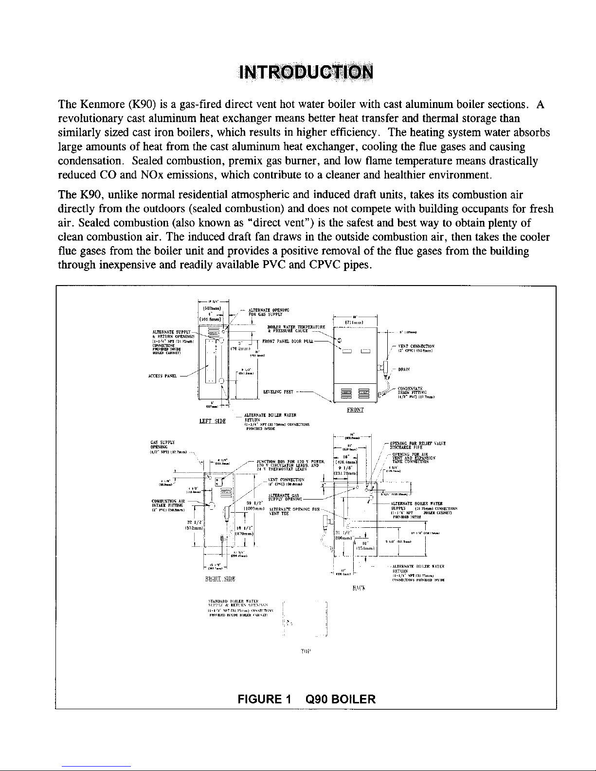
TheKenmore(K90) is a gas-fireddirectventhot waterboiler with castaluminumboiler sections.A
revolutionarycastaluminumheatexchangermeansbetterheattransferandthermalstoragethan
similarly sizedcastironboilers, which resultsin higherefficiency. Theheatingsystemwaterabsorbs
largeamountsof heatfromthe castaluminumheatexchanger,coolingthe flue gasesandcausing
condensation.Sealedcombustion,premix gasburner,andlow flametemperaturemeansdrastically
reducedCOandNOxemissions,which contributeto a cleanerandhealthierenvironment.
TheK90, unlike normalresidentialatmosphericandinduceddraft units, takesits combustionair
directly from the outdoors(sealedcombustion)anddoesnotcompetewith buildingoccupantsfor fresh
air. Sealedcombustion(alsoknownas "direct vent") isthesafestandbestway to obtainplentyof
cleancombustionair. The induceddraftfandrawsin the outsidecombustionair, thentakesthecooler
flue gasesfrom theboiler unit andprovidesapositiveremovalof theflue gasesfrom thebuilding
throughinexpensiveandreadilyavailablePVC andCPVCpipes.
I
_T_N_ _rslLE_ WaTE_ i.
Tilt'
FIGURE 1 Q90 BOILER
Page 5

TABLE 1 SEA LEVEL RATINGS - NATURAL AND PROPANE GASES
+ + Heating Net I =B =R Shipping Flue
Model Input *(MBH) Capacity Rating Weight Dia.
*(MBH) *(MBH) (lbs.)
K90-50 50 45 39 220 2" CPVC & Pvc
K90-75 75 68 59 220 2" CPVC & Pvc
K90-100 100 90 78 220 2" cPVC & Pvc
"1 MBH = 1,000 Btuh Btuh = British Thermal Units Per Hour
These low pressure gas-fired hot water boilers are design certified by CSA International for use with natural
and propane gases. The boilers are constructed and hydrostatically tested for a maximum working pressure of
50 psig (pounds per square inch gage) in accordance with A.S.M.E. (American Society of Mechanical
Engineers) Boiler and Pressure Vessel Code Section IV Standards for heating boilers.
+ + AFUE (Annual Fuel Utilization Efficiency) and Heating Capacity is based on the D.O.E.
(Department of Energy) test procedure.
The K90-50, 75 and 100 Boilers are certified in accordance with ANSI (American National
Standards Institute) Z21.13 standards as gas-fired, direct vent, condensing, hot water boilers.
The Heating Capacity indicates the amount of heat available after subtracting the losses up the stack.
Most of this heat is available to heat water. A small portion is heat from the jacket and surfaces of the
boiler, and it is assumed that this heat stays in the structure. The Net I=B=R Rating represents the
portion of the remaining heat that can be applied to heat the radiation or terminal units (i.e. finned
tube baseboard, cast iron radiators, radiant floor, etc.). The difference between the Heating Capacity
and the Net I=B=R Rating, called the piping and pickup allowance, establishes a reserve for heating
the volume of water in the system and offsetting heat losses from the piping. The Net I=B=R Ratings
shown are based on a piping and pickup factor of 1.15 in accordance with the I=B=R Standard as
published by the Hydronics Institute. The Net I=B=R Rating of the boiler selected should be greater
than or equal to the calculated peak heating load (heat loss) for the building or area(s) served by the
boiler and associated hot water heating systems. The manufacturer should be consulted before
selecting a boiler for installations having unusual piping and pickup requirements.
BOILERS FOR USE AT HIGH ALTITUDE
The K90 boilers are factory equipped for operation at altitudes ranging from 0-2,000 feet above sea
level. For use of these boilers at altitudes above 2,000 feet above sea level, the gas input ratings
(MBH) must be reduced.
U.S.A. ONLY: For altitudes above 2,000 feet above sea level, input ratings should be reduced as
shown in tables 1A, C, & E for natural gas boilers or in tables 1B, D & F for propane fired boilers.
Reduced input ratings are achieved by the natural deration of the gas at higher elevations and fine
tuned by adjusting the manifold pressure.
CANADA ONLY: For altitudes in the range of 2,000-4,500 feet above sea level, boilers may be
field equipped for use at high altitude by using a certified high altitude conversion kit. The change in
main burner orifice size results in a 10% reduction of the boiler gas input rating (MBH).
Page 6
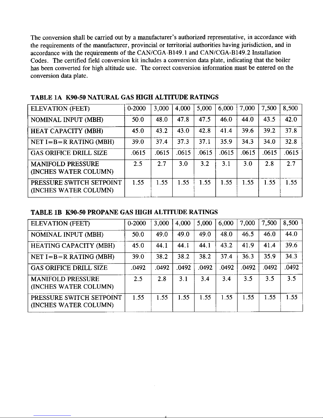
Theconversionshallbecarriedout by a manufacturer's authorized representative, in accordance with
the requirements of the manufacturer, provincial or territorial authorities having jurisdiction, and in
accordance with the requirements of the CAN/CGA-B149.1 and CAN/CGA-B149.2 Installation
Codes. The certified field conversion kit includes a conversion data plate, indicating that the boiler
has been converted for high altitude use. The correct conversion information must be entered on the
conversion data plate.
TABLE 1A K90-50 NATURAL GAS HIGH ALTITUDE
RATINGS
5,000 6,000
47.5 46.0
42.8 41.4
37.1 35.9
.0615 .0615
3.2 3.1
ELEVATION (FEET) 0-2000 3,000 4,000 7,000 7,500 8,500
NOMINAL INPUT (MBH) 50.0 48.0 47.8 44.0 43.5 42.0
HEAT CAPACITY (MBH) 45.0 43.2 43.0 39.6 39.2 37.8
NET I=B=R RATING (MBH) 39.0 37.4 37.3 34.3 34.0 32.8
GAS ORIFICE DRILL SIZE .0615 .0615 .0615 .0615 .0615 .0615
MANIFOLD PRESSURE 2.5 2.7 3.0 3.0 2.8 2.7
(INCHES WATER COLUMN)
PRESSURE SWITCH SETPOINT 1.55 1.55 1.55 1.55 1.55 1.55 1.55 1.55
(INCHES WATER COLUMN)
TABLE 1B K90-50 PROPANE GAS HIGH ALTITUDE RATINGS
ELEVATION (FEET) 0-2000 3,000 4,000 5,000 6,000 7,000 7,500 8,500
NOMINAL INPUT (MBH) 50.0 49.0 49.0 49.0 48.0 46.5 46.0 44.0
HEATING CAPACITY (MBH) 45.0 44.1 44.1 44.1 43.2 41.9 41.4 39.6
NET I=B =R RATING (MBH) 39.0 38.2 38.2 38.2 37.4 36.3 35.9 34.3
GAS ORIFICE DRILL SIZE .0492 .0492 .0492 .0492 .0492 .0492 .0492 .0492
MANIFOLD PRESSURE 2.5 2.8 3.1 3.4 3.4 3.5 3.5 3.5
(INCHES WATER COLUMN)
PRESSURE SWITCH SETPOINT 1.55 1.55 1.55 1.55 1.55 1.55 1.55 1.55
(INCHES WATER COLUMN)
Page 7

TABLE 1C K90-75 NATURAL GAS HIGH ALTITUDE RATINGS
ELEVATION (FEET)
NOMINAL INPUT (MBH)
HEATING CAPACITY (MBH)
NET I=B=R RATING (MBH)
GAS ORIFICE DRILL SIZE
MANIFOLD PRESSURE
(INCHES WATER COLUMN)
PRESSURE SWITCH SETPOINT
(INCHES WATER COLUMN)
0-2000 l
75.0
68.0
58.9
.0760
2.5
3,000 4,000 5,000 6,000 7,000 7,500 8,500
70.0 69.0 68.0 63.5 58.0 56.5 52.0
63.0 62.1 61.2 57.2 52.2 50.9 46.8
54.6 53.8 53.0 49.6 45.2 44.1 40.6
.0760 .0760 .0760 .0760 .0760 .0760 .0760
2.7 2.8 3.0 2.8 2.6 2.3 2.1
1.35 1.35 1.35 1.35 1.35 1.35 1.35 1.35
TABLE 1D K90-75 PROPANE GAS HIGH
ELEVATION (FEET)
NOMINAL INPUT (MBH)
HEATING CAPACITY (MBH)
NET I=B=R RATING (MBH)
GAS ORIFICE DRILL SIZE
MANIFOLD PRESSURE
(INCHES WATER COLUMN)
PRESSURE SWITCH SETPOINT
(INCHES WATER COLUMN)
ALTITUDE RATINGS
0-2000 3,000 4,000 5,000 6,000 7,000 7,500 8,500
75.0 70.0 69.0 67.0 66.0 64.5 64.0 62.0
68.0 63.0 62.1 60.3 59.4 58.1 57.6 55.8
58.9 54.6 53.8 52.3 51.5 50.4 49.9 48.4
.0605 .0605 .0605 .0605 .0605 .0605 .0605 .0605
2.5 2.4 2.3 2.2 2.2 2.2 2.3 2.3
1.35 1.35 1.35 1.35 1.35 1.35 1.35 1.35
TABLE 1E K90-100 NATURAL GAS HIGH ALTITUDE RATINGS
ELEVATION (FEET)
NOMINAL INPUT (MBH)
HEATING CAPACITY (MBH)
NET I=B=R RATING (MBH)
GAS ORIFICE DRILL SIZE
MANIFOLD PRESSURE
(INCHES WATER COLUMN)
PRESSURE SWITCH SETPOINT
(INCHES WATER COLUMN)
0-2000 3,000 4,000 5,000 6,000 7,000 7,500 8,500
100.0 97.0 96.0 95.0 90.0 84.0 82.0 76.0
90.0 87.3 86.4 85.5 81.0 75.6 73.8 68.4
78.0 75.7 74.9 74.1 70.2 65.5 64.0 59.3
.0860 .0860 .0860 .0860 .0860 .0860 .0860 .0860
2.5 2.9 3.3 3.7 3.4 3.2 2.9 2.6
1.17 1.17 1.17 1.17 1.17 1.17 1.17 1.17
TABLE 1F K90-100 PROPANE GAS HIGH ALTITUDE RATINGS
ELEVATION (FEET)
NOMINAL INPUT (MBH)
HEATING CAPACITY (MBH)
NET I=B =R RATING (MBH)
GAS ORIFICE DRILL SIZE
MANIFOLD PRESSURE
(INCHES WATER COLUMN)
PRESSURE SWITCH SETPOINT
(INCHES WATER COLUMN)
0-2000 3,000 4,000 5,000 6,000 7,000 7,500 8,500
100.0 95.0 94.0 92.0 92.0 91.5 91.5 91.0
90.0 85.5 84.6 82.8 82.8 82.4 82.4 81.9
78.0 74.1 73.3 71.8 71.8 71.4 71.4 71.0
.0670 .0670 .0670 .0670 .0670 .0670 .0670 .0670
2.5 2.7 2.9 3.1 3.2 3.3 3.4 3.5
1.17 1.17 1.17 1.17 1.17 1.17 1.17 1.17
6
Page 8

1. Read the entire installation manual before beginning the installation. Failure to follow these rules
for safe installation and operation and these instructions could cause a malfunction of the boiler
and result in death, serious bodily injury, and/or property damage.
2. Check all applicable state and local building codes and utility company requirements before
installation. The installation must conform with these requirements in their entirety. In the absence
of these codes, use NFPA Installation Codes and good industry practice.
3. Before servicing the boiler - allow the boiler to cool. Always shut off any electricity and gas
supply connected to the boiler prior to servicing.
4. Inspect gas line for leaks.
5. Be certain gas input rate is correct. Over firing may result in early failure of the boiler sections.
This may cause dangerous operation. Under firing may result in too much air for the pre-mix
burner causing poor or loss of combustion.
6. Never vent the products of combustion from this boiler to an enclosed space. Always vent to the
outdoors. Never vent to another room or to inside a building.
7. Be sure there is adequate outdoor air supply to boiler for complete combustion.
8. Follow a regular service and maintenance schedule for efficient and safe operation.
9. Keep boiler area clean of debris and free of combustible and flammable materials.
10. Proper through the wall or through the roof combustion venting shall be in accordance with the
materials and methods described in this manual. Installation must comply with local codes.
11. This boiler and related hot water heating systems are not do it yourself items. They must be
installed and serviced by qualified professionals.
WARNING
This boiler has been equipped for residential installations. If used for commercial applications, any
additional code requirements must be adhered to for installation. This may require additional controls
including but not limited to a low water cut off, a manual reset high temperature limit, and wiring
and/or piping modifications. The manufacturer is not responsible for any field installation changes
made to a boiler installation which are not described or acknowledged in this manual.
Complete all of the following prior to installing the boiler.
A. CODES
This boiler product is a gas-fired, direct vent, condensing boiler and must be installed in
accordance with all applicable federal, state and local building codes including, but not limited to
the following :
United States - Installation shall conform with National Fuel Gas Code (NFPA-54/ANSI Z223. l-
latest edition)
Canada - Installation shall be in accordance with CAN/CGA-B 149.1 and .2 installation
codes.
Page 9

Whererequiredby theauthorityhavingjurisdiction, theinstallationmustconformto theAmerican
Societyof MechanicalEngineersSafetyCodefor ControlsandSafetyDevicesfor Automatically
FiredBoilers, No.CSD-1.
Theinstallation must conform to the requirements of the authority having jurisdiction or, in the
absence of such requirements, to the National Fuel Gas Code, ANSI Z223.1 - latest revision.
Installers - Follow local regulations with respect to installation of CO (Carbon Monoxide)
Detectors. Follow maintenance recommendations in this manual.
Teclmiciens - Veuillez vous conformer _tla r6glementation en vigeur concernant 1"installation
des d_tecteurs d'oxyde de carbone. Suivre les consignes d'entretien figurant clans
le manuel d'instruction ci-joint.
B. BOILER SIZING
• Check to be sure you have selected the K90 boiler with the proper capacity before starting the
installation. The I=B=R Rating of the boiler selected should be greater than or equal to the
calculated peak heating load (heat loss) for the building or area(s) served by the boiler and
associated hot water heating systems. See the table "BOILER RATINGS AND
CAPACITIES".
• Heat loss calculations should be based on approved industry methods.
C. CONSIDERATIONS FOR BOILER LOCATION
Before selecting a location for the boiler, the following should be considered. Each boiler
considered for installation must be:
• Supplied with the correct type of gas (natural gas or propane).
• Connected to a suitable combustion air intake piping system to supply the correct amounts of
fresh (outdoor) air for combustion. (maximum length 80' for K90-100 boiler, and maximum
length 100' for K90-75 and K90-50 boilers).
• Connected to a suitable venting system to remove the hazardous products of gas combustion
(maximum length 80' for K90-100 boiler, and maximum length 100' for K90-75 and K90-50
boilers).
• Connected to a suitable hot water heating system.
• Supplied with a suitable electrical supply for all boiler motors and controls.
• Connected to a properly located thermostat or operating control. (not included with boiler)
• Placed on level surface (must NOT be installed on carpeting)
• Condensate drain line must be pitched down to floor drain or external condensate pump with
reservoir at _A"per foot (wood frame or blocks may be used to raise boiler).
Page 10
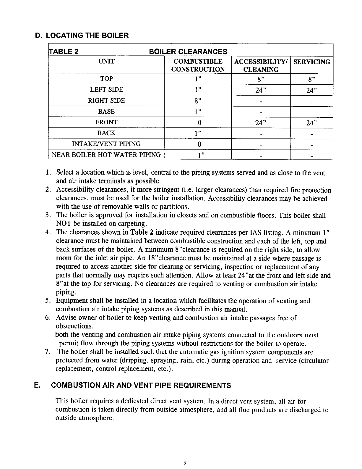
D. LOCATING THE BOILER
TABLE 2
L_IT
TOP
LEFT SIDE
RIGHT SIDE
BASE
FRONT
BACK
INTAKE/VENT PIPING
NEAR BOILER HOT WATER PIPING
BOILER CLEARANCES
COMBUSTIBLE
CONSTRUCTION
1"
1"
8"
1"
0
l"
o
1"
ACCESSIBILITY/
CLEANING
8"
24"
24"
SERVICING
8"
24"
24"
1. Select a location which is level, central to the piping systems served and as close to the vent
and air intake terminals as possible.
2. Accessibility clearances, if more stringent (i.e. larger clearances) than required fire protection
clearances, must be used for the boiler installation. Accessibility clearances may be achieved
with the use of removable walls or partitions.
3. The boiler is approved for installation in closets and on combustible floors. This boiler shall
NOT be installed on carpeting.
4. The clearances shown in Table 2 indicate required clearances per IAS listing. A minimum I"
clearance must be maintained between combustible construction and each of the left, top and
back surfaces of the boiler. A minimum 8"clearance is required on the right side, to allow
room for the inlet air pipe. An 18"clearance must be maintained at a side where passage is
required to access another side for cleaning or servicing, inspection or replacement of any
parts that normally may require such attention. Allow at least 24"at the front and left side and
8"at the top for servicing. No clearances are required to venting or combustion air intake
piping.
5. Equipment shall be installed in a location which facilitates the operation of venting and
combustion air intake piping systems as described in this manual.
6. Advise owner of boiler to keep venting and combustion air intake passages free of
obstructions.
both the venting and combustion air intake piping systems connected to the outdoors must
permit flow through the piping systems without restrictions for the boiler to operate.
7. The boiler shall be installed such that the automatic gas ignition system components are
protected from water (dripping, spraying, rain, etc.) during operation and service (circulator
replacement, control replacement, etc.).
E. COMBUSTION AIR AND VENT PIPE REQUIREMENTS
This boiler requires a dedicated direct vent system. In a direct vent system, all air for
combustion is taken directly from outside atmosphere, and all flue products are discharged to
outside atmosphere.
Page 11
Combustion air and vent pipe connections must terminate together in the same atmospheric
pressure zone, either through the roof or sidewall (roof termination preferred). See Fig.9 & 10
for required clearances.
CAUTION
KEEP BOILER AREA CLEAN OF DEBRIS AND FREE OF FLAMMABLE AND
COMBUSTIBLE MATERIALS, VAPORS AND LIQUIDS
WARNING
When vent pipe is exposed to temperatures below freezing, such as when it passes through an
unheated space or when a chimney is used as a raceway, vent pipe must be insulated with
l/2"Armaflex or equivalent. In extreme cold climate areas, use ¾ "Armaflex or equivalent.
Combustion air must be clean outdoor air. Combustion air must not be taken from inside structure
because that air frequently is contaminated by halogens, which include fluorides, chlorides,
phosphates, bromides and iodides. These elements are found in aerosols, detergents, bleaches,
cleaning solvents, salts, air fresheners, paints, adhesives and other household products.
Locate combustion air inlet as far away as possible from swimming pool and swimming pool pump
house.
All combustion air and vent pipes must be airtight and watertight. Combustion air and vent piping
must also terminate exactly as shown in Fig.9 or 10.
Vent connections serving appliances vented by natural draft shall not be connected into any portion of
mechanical draft systems operating under positive pressure.
Solvent cements are combustible. Keep away from heat, sparks, and open flame. Use only in well
ventilated areas. Avoid breathing in vapor or allowing contact with skin or eyes.
FAILURE TO FOLLOW THE AFOREMENTIONED WARNINGS COULD RESULT IN FIRE,
PROPERTY DAMAGE, PERSONAL INJURY, OR DEATH.
F. CONDENSATE DRAIN REQUIREMENTS
Condensate drain line to be pitched down to floor drain at a minimum of ¼"per foot. An external
condensate pump (not furnished) may be used if floor drain is not available. The condensate pump
must be designed for flue gas condensate application
NOTE: 1. Condensate trap is built into the boiler, an external trap is not required and should not
be used.
2. Wood frame or blocks may be used to raise the boiler to maintain drain pitch or to be
above external condensate pump reservoir.
3. There is a 115 volt AC receptacle provided on the service switch junction box which
is located at the boiler right side, to provide power for an external condensate pump
(if needed).
10
Page 12
G. FOUNDATION REQUIREMENTS
Boiler must be placed on level surface. Boiler is NOT to be installed on carpeting.
NOTE: 1. If boiler is not level condensate drain lines will not function properly. Adjustable feet
are located on the boiler to make up for minor surface irregularities or tilt.
2. Wood frame or blocks may be used to raise boiler to maintain drain pitch or to be
above external condensate pump reservoir.
H. REMOVAL OF EXISTING BOILER FROM COMMON VENT SYSTEM
When an existing boiler is removed from a common venting system, the common venting system
is likely to be too large for proper venting of the appliances remaining connected to it. At the time
of removal of an existing boiler, the following steps shall be followed with each appliance
remaining connected to the common venting system placed in operation, while the other appliances
remaining connected to the common venting system are not in operation.
1. Seal any unused openings in the common venting system.
2. Visually inspect the venting system for proper size and horizontal pitch and determine there is
no blockage or restrictions, leakage, corrosion and other deficiencies which could cause an
unsafe condition.
3. Insofar as is practical, close all building doors and windows and all doors between the space
in which the appliances remaining connected to the common venting system are located and
other spaces of the building. Turn on clothes dryer and any appliance not connected to the
common venting system. Turn on any exhaust fans, such as range hoods and bathroom
exhaust, so they will operate at maximum speed. Do not operate a summer exhaust fan. Close
fire dampers.
4. Place in operation the appliance being inspected. Follow the lighting instructions. Adjust
thermostat so appliances will operate continuously.
5. Test for spillage at the draft hood relief opening after 5 minutes of main burner operation. Use
the flame of a match or candle, or the smoke from a cigarette, cigar or pipe.
6. After it has been determined that each appliance remaining connected to the common venting
system properly vents when tested as outlined above, return doors, windows, exhaust fans and
any other gas-burning appliance to their previous condition of use.
7. Any improper operation of the common venting system should be corrected so the installation
conforms with the National Fuel Code, NFPA-54/ANSI -Z223. l-latest revision, or section 5
of CAN/CGA-B149 for Canadian standards. When resizing any portion of the common
venting system, the common venting system should be resized to approach the minimum size
as determined using the appropriate tables in part I 1 in the National Fuel Gas Code, NFPA-
54/ANSI- Z223. l-latest revision, or section 5 of CAN/CGA-B149 for Canadian standards.
PLACING THE BOILER
The boiler should be placed to provide the most direct connections to the combustion air, vent and
system piping as possible.
Place crated boiler as close to selected location as possible and uncrate boiler. The uncrated boiler
may be moved into position with an appliance dolly or 2-wheel hand truck. The dolly or hand truck
should be inserted under the left hand side of the boiler. It is possible to slide the boiler for a short
distance on a smooth floor or surface.
11
Page 13
NOTE: Refer to manual section "LOCATING THE BOILER" for required clearances for servicing
and maintenance.
CAUTION
Copper supply and return piping must NOT be installed directly into aluminum boiler section castings
due to galvanic corrosion between dissimilar metals. Iron or steel bushings or pipe nipples should be
used between copper system piping and boiler to make final connection to boiler. Also, the use of
dielectric unions is acceptable. The packaged boiler is furnished with iron piping in the front boiler
section for the supply and return connections.
When the installation of the boiler is for a new heating system, first install all of the radiation units
(panels, radiators, baseboard, or tubing) and the supply and return mains. After all heating system
piping and components have been installed, make final connection of the system piping to the boiler.
A hot water boiler installed above radiation level must be equipped with a low water cut off device. A
periodic inspection is necessary, as is flushing of float type devices, per low water cut off
manufacturers specific instructions.
A. SUPPLY AND RETURN LINES
The packaged boiler unit is set up to receive 1_,_"NPT supply and return piping from top access.
The boiler unit can also be piped from the left side by turning the supply elbow, and from the rear
of the unit by removing plugs in the rear boiler section.
NOTE: The circulator pump and isolation valves are furnished within a carton inside the boiler
cabinet and can be installed at the installer preferred location.
12
Page 14
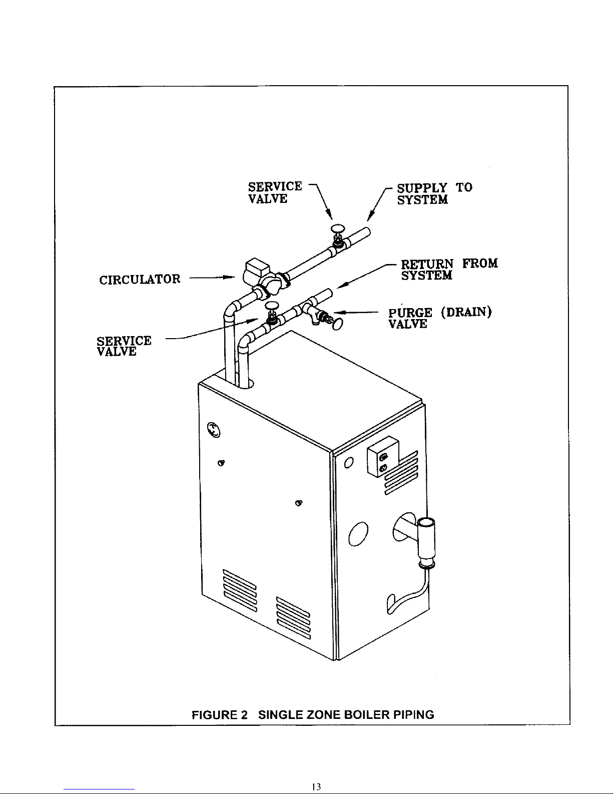
SERVICE -_
VALVE
SUPPLY TO
f SYSTEM
CIRCULATOR
SERVICE
VALVE
RETURN FROM
_J_'-SYSTEM
--_ PURGE (DRAIN)
VALVE
FIGURE 2 SINGLE ZONE BOILER PIPING
13
Page 15
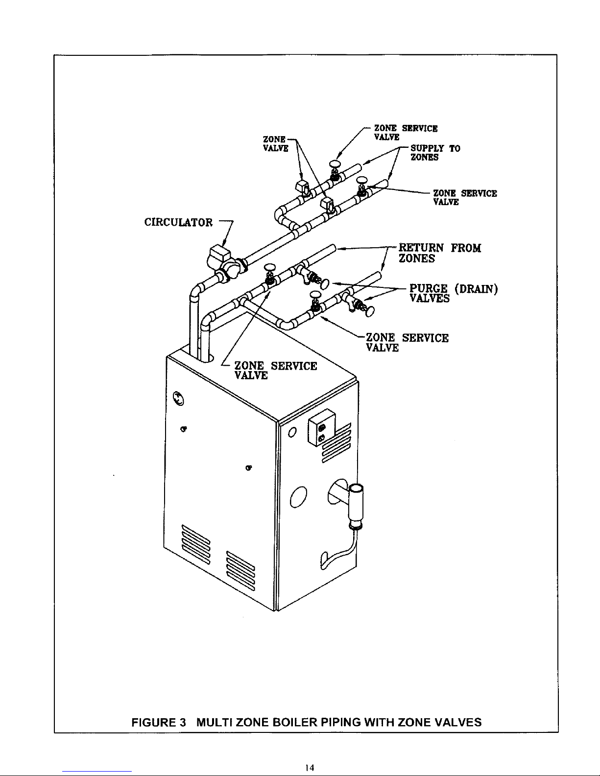
VALVE
f OI_E SERVICE
VALVE
SUPPL TO
ZONES
CIRCULATOR
ZONE SERVICE
VALVE
FROM
ZONES
(DRAIN)
VALVES
ZONE SERVICE
VALVE
ZONESERVICE
VALVE
FIGURE 3 MULTI ZONE BOILER PIPING WITH ZONE VALVES
14
Page 16
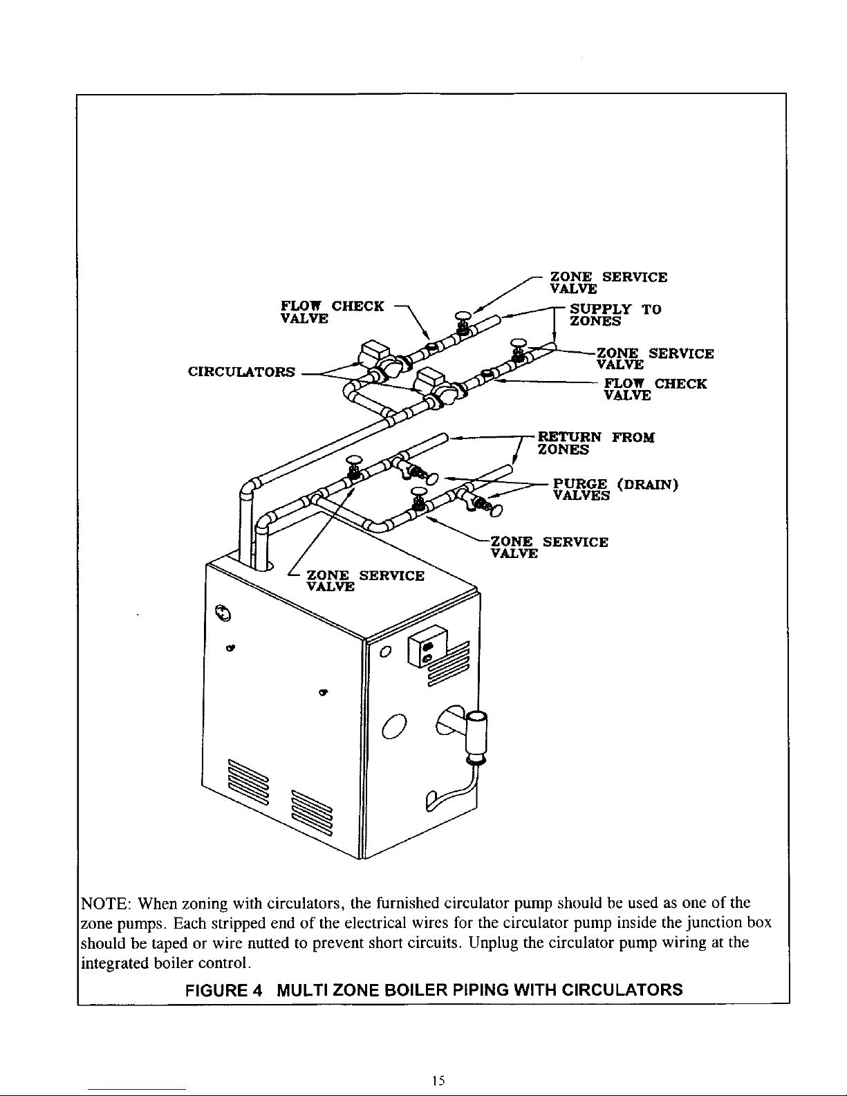
FLOW CHECK --_
VALVE
CIRCULATORS
ZONE SERVICE
VALVE
TO
ZONES
ZONE SERVICE
VALVE
FLOW CHECK
VALVE
FROM
ZONES
PURGE (DRAIN)
VALVES
ZONE SERVICE
VALVE
SERVICE
VALVE
NOTE: When zoning with circulators, the furnished circulator pump should be used as one of the
zone pumps. Each stripped end of the electrical wires for the circulator pump inside the junction box
should be taped or wire nutted to prevent short circuits. Unplug the circulator pump wiring at the
integrated boiler control.
FIGURE 4 MULTI ZONE BOILER PIPING WITH CIRCULATORS
15
Page 17

RELIEF VALVE
DISCHARGE
PIPING
FIGURE 5 RELIEF VALVE DISCHARGE PIPING
B. PRESSURE RELIEF VALVE
The boiler is furnished with a factory installed relief valve in the top of the boiler. Provide ¾"
piping from the supplied relief valve to a local floor drain, but leave an air gap between piping and
drain. No shutoff of any description shall be placed between safety relief valve and the boiler, or
on the discharge pipes between such safety valve and the atmosphere. Installation of the safety
relief valve shall conform to ANSI/ASME Boiler and Pressure Vessel Code, Section IV. The
manufacturer is not responsible for any water damage.
C. EXPANSION TANK AND MAKE-UP WATER
Determine required system fill pressure, system design temperature, and system water content.
Boiler contains 2.6 gallons (U.S.). Size expansion tank accordingly. Consult expansion tank
manufacturer for proper sizing information. Connect properly sized expansion tank (not furnished)
as shown in Fig.6 for diaphragm type expansion tank and Fig.7 for conventional closed type
expansion tanks. For diaphragm type expansion tanks, adjust the tank air pressure to match the
system fill pressure. Install air vent (furnished) as shown for diaphragm type expansion tank
system only. Install make-up water connections as shown and per local codes. If a pressure
reducing valve is used, adjust to match the system fill pressure. In connecting the cold make-up
water supply to the boiler, make sure that clean water supply is available. When the water supply
is from a well or pump, a sand strainer should be installed at the pump.
16
Page 18

MANUAL FILL
VALVE
AIR
BUSHING"
COLD WATER
-FILL
DIAPHRAGM TYPE
EXPANSION TANK
COMBINATION QUICK FILL
VALVE, STRAINER, CHECK
VALVE AND PRESSURE
REDUCING VALVE
TEE"
_" NIPPLE (FURNISHED
INSTALLED ON
PACKAGED BOILER)
3/4" STREET ELL"
• - FURNISHED IN
PARTS BAG.
FIGURE 6 DIAPHRAGM TYPE EXPANSION TANK PIPING
17
Page 19

CLOSED TYPE
E_°ANSION TANK
L
MANUAL
VALVE
COLD
FILL
_CHEUK AND PRESSURE
REDUCING VALVE
FIGURE 7 CONVENTIONAL(closed type) EXPANSION TANK PIPING
]8
Page 20

OPEN
DRAIN PIPE TO
BE PITCHED DOWN
TO FLOOR DRAIN
AT A MINIMUM
I/4" PER FOOT
TO
DRAIN
THREADED NIPPLE
(INSTALLED)
CONDENSATE
DRAIN
PVC TEE
I/2"SMPxl/2"SMPxl/2 "NPT
FURNISHED IN PARTSBAG
FIGURE 8 CONDENSATE - DRAIN PIPING
D. CONDENSATE DRAIN PIPING
The condensate trap is built into the boiler, an external trap is not required and should NOT be
used.
Provide '/2"PVC condensate drain and fittings. Condensate drain to be pitched down to floor drain
at a minimum of ¼"per foot.
Install furnished I/z"PVC tee to overflow fitting as shown in Fig.8.
The 1/2"diameter schedule 40 PVC or CPVC condensate drain piping and pipe fittings must
conform to ANSI standards and ASTM D1785 or D2846. Schedule 40 PVC or CPVC cement and
primer must conform to ASTM D2564 or F493. In Canada, use CSA or ULC certified schedule 40
PVC or CPVC drain pipe and cement.
A condensate pump with a reservoir (not furnished) may be used to remove condensate to a drain
line (sanitary line) above boiler if a floor drain is not available or is inaccessible.
19
Page 21

E. FILLING CONDENSATE TRAP WITH WATER
ON THE INITIAL START UP THE CONDENSATE TRAP MUST BE MANUALLY FILLED WITH
WATER
The following are the steps required to initially fill the condensate trap for start up, these steps are
only required at the initial start up or if maintenance requires draining of the condensate trap:
1. Disconnect the vent condensate drain line from the bottom of the vent tee on the boiler.
2. Pour about 1 cup of cold tap water into the vent drain line with a proper funnel.
3. Excess water should go through the overflow and out through the condensate drain line.
Verify proper operation of the drain line (or external condensate pump if used).
4. Reinstall the vent drain line.
F. CHILLED WATER PIPING
The boiler, when used in connection with a refrigeration system, must be installed so the chiller
medium is piped in parallel with the boiler with appropriate valves to prevent the chilled medium
from entering the boiler.
The boiler piping system of a hot water boiler connected to heating coils is located in air handling
units where they may be exposed to refrigerated air circulation must be equipped with flow control
valves or other automatic means to prevent gravity circulation of the boiler water during cooling
cycle.
A. CONNECTIONS AND TERMINATION
For boilers connected to gas vents or chimneys, vent installations shall be in accordance with part
7, Venting of Equipment, of the National Fuel Gas Code, ANSI Z223. l-latest revision,
CAN/CGA-B149.1 and B149.2, and applicable provisions of the local building codes.
Provisions for combustion and ventilation air must be in accordance with section 5.3, Air For
Combustion and Ventilation, of the National Fuel Gas Code,ANSI Z223. l-latest revision,
CAN/CGA-B149.1 and B149.2, or applicable provisions of the local building code.
These boilers require a dedicated direct vent system. All air for combustion is taken directly from
outdoors through the combustion air intake pipe. All flue products are discharged to the outdoors
through the vent pipe.
1. See Fig.9 & 10 for combustion air and vent pipe roof and sidewall termination. (Roof
termination is preferred) Combustion air and vent pipes must terminate together in same
atmospheric pressure zone as shown. Construction through which vent and air intake pipes
may be installed is a maximum 24 inches, minimum 1_"thickness.
2. Combustion air and vent pipe fittings must conform to American National Standards Institute
(ANSI) standards and American Society for Testing and Materials (ASTM) standards D1784
(schedule-40 CPVC), D1785 (schedule-40 PVC), D2665 (PVC-DWV), D2241 (SDR-21 and
SDR-26 PVC), D2661 (ABS-DWV), or F628 (schedule-40 ABS). Pipe cement and primer
must conform to ASTM standards D2564 (PVC) or D2235 (ABS).
2O
Page 22

.
.
m
In Canada construct all combustion air and vent pipes for this unit of CSA or ULC certified
schedule-40 CPVC, schedule-40 PVC, PVC-DWV or ABS-DWV pipe and pipe cement.
SDR pipe is NOT approved in Canada.
Combustion air and vent piping connections on boiler are sized for 2" pipe. Any pipe size
change (to 3") must be made outside of the boiler casing in a vertical run of pipe to allow for
proper drainage of vent condensate. Due to potential for flue gas temperatures over 155°F,
the first five (5) feet of vent pipe must be CPVC, the remaining vent pipe can be PVC. If any
elbows are employed within the first 5 feet of vent, they must be CPVC too. Two (2) - 30"
pieces of 2" CPVC pipe are furnished with the boiler.
NOTE: The transition from 2" pipe to 3" pipe must be made in a vertical run.
Combustion air and vent piping lengths;The first 5 feet of "TOTAL EQUIVALENT
LENGTH" of vent piping run must be CP¥C it corresponds as follows:
BOILER 2" PIPE 2" PIPE 3" PIPE 3" PIPE
SIZE MINIMUM MAXIMUM MINIMUM MAXIMUM
VENTING VENTING VENTING VENTING
K90-100
2 FEET IN
LENGTH
+
4-90 °
ELBOWS
15 FEET IN
LENGTH
AND UP TO
4-90 °
ELBOWS
15 FEET IN
LENGTH
+
4-90 °
ELBOWS
80 FEET IN
LENGTH
AND UP TO
4-90 °
ELBOWS
2 FEET IN 20 FEET IN 20 FEET IN 100 FEET IN
K90-75 LENGTH LENGTH LENGTH LENGTH
_L + AND UP TO + AND UP TO
K90-50 4-90° 4-90° 4-90° 4-90°
ELBOWS ELBOWS ELBOWS ELBOWS
The length of pipe is counted from the boiler jacket (air intake pipe) or from vent tee (vent pipe).
For additional elbows, reduce the maximum vent length as shown:
2" 90 degree elbow - 1 1/2 feet per additional elbow.
3" 90 degree elbow - 3 feet per additional elbow.
Example: To add 2 additional 90 degree elbows to a 3"pipe for a K90-75 boiler.
Each elbow is 3 additional feet per 90 degree elbow for a total of 6 feet. (1 elbow @ 3
feet + 1 elbow @ 3 feet = 6 additional feet of pipe) The total additional pipe is then
subtracted from the maximum allowable pipe length to give the new maximum length of
94 feet with 6, 90 degree elbows. ("TOTAL EQUIVALENT LENGTH": Original 100
feet max. - 6 feet for 2 additional elbows = new 94 feet maximum length).
.
Combustion air and vent piping to be pitched back to boiler at minimum ¼ "per foot from
intake and vent terminals so that all moisture in combustion air and vent piping drains to
boiler. Pipes must be pitched continuously with no sags or low spots where moisture can
accumulate and block the flow of air or flue gas. Combustion air and vent pipes must be
airtight and watertight.
21
Page 23

.
.
Consideration for the following should be used when determining an appropriate location for
termination of combustion air and vent piping:
• Comply with all clearances required as stated in paragraph 7.
• Termination should be positioned where vent vapors will not damage plants/shrubs or air
conditioning equipment.
• Termination should be positioned so that it will not be effected by wind eddy, air born
leaves, snow, or recirculated flue gases.
• Termination should be positioned where it will not be subjected to potential damage by
foreign objects, such as stones, balls, etc..
• Termination should be positioned where vent vapors are not objectionable.
• Put vent on a wall away from the prevailing winter wind. Locate or guard the vent to
prevent accidental contact with people or pets.
• Terminate the vent above normal snowline. Avoid locations where snow may drift and
block the vent. Ice or snow may cause the boiler to shut down if the vent becomes
obstructed.
• Under certain conditions, flue gas will condense, forming moisture, and may be corrosive.
In such cases, steps should be taken to prevent building materials at the vent from being
damaged by exhaust of flue gas.
The venting system shall terminate at least 3 feet above any forced air inlet (except the
boiler's combustion air inlet) within 10 feet. The venting system shall terminate at least 12
inches from any air opening into any building. The bottom of the vent shall be located at least
12 inches above grade. Termination of the vent shall be not less than 7 feet above an adjacent
public walkway. The vent terminal shall not be installed closer than 3 feet from the inside
corner of an L shaped structure. Termination of the vent should be kept at least 3 feet away
from vegetation. The venting system shall terminate at least 4 feet horizontally from, and in
no case above or below, unless a 4 foot horizontal distance is maintained, from electric
meters, gas meters, regulators, and relief equipment.
M\INT\I _, 12" MINIM[ M
CLE\R\NfE \[I()XE ]I[(;]IE_;T
:\NTICIP\TED S;NO_I LEVEL
FIGURE 9 ROOF VENT / INTAKE TERMINATIONS
22
Page 24

FIGURE 10 SIDEWALL VENT/INTAKE TERMINATIONS
23
Page 25

2" (50,Smm) COMBUSTION AIR
INTAKE P_PING
2" (60,8nu,n } CPVC VENT PIPING
(FURNISHED)
2" (60 8turn) CPVC COUPLING
(FURNISHED
1.52m
VENT/INTAKE
_-TERMINATION8
2" (60,gmm) OIAMETER VENT AND
COMBUSTION AIR tNTAKE
PIPING -
15' (4.57m) MAXIMUM LENGTH TOTAL
WITH 4 - D0" EU_OWSFOR Qg0.100
26'(6.t 0m) _M LENGTH TOTALwm-I
4 - Go*ELBOWS FOR Og0.78 AND GgO. SO
2' (.8t m)M_NIMU_ LENGTH TOTAL
WrTH4 - gO"ELBOWS FOR ALL
(FU4RNISHED)
3"(76.2mm) COMBUSTION AIR
INTAKEPIPING
2" {50.Smm) CPVC VENT PIPING
(FURN{SHEJD) "_
2- (5,0.Smm)CPVCCOUPLING
(FURNISHED)
V=_-NTPfP_NG
TRANSITION PITTING
_ 2"(_o.smm)O TO 3" (78.2mm)O IN
_ VERTtCAL RUN
3"(7O2nv_) DIAMETERVENT
COMBU,_ A._ INTAKEPIPING
FORQ_- 100
SO*(24.3&'n)MAXIMUM LENGTH TOTAL
15'(6.t0m) MINIMUM LENGTHTOTAL
WITH 4 - 90" ELBOWS
5' IO(T(30ASm) MAXIMUM LENGTH TOTAL
1.5_Jn WN_ 4 - g0"ELBOWS
20'16,1_1MIN/I, AUMLENGTH TOTAL
W_TH4 - 90" ELBOW,S
TRANSITION FITTING
2" (50.Smm) 0 TO 3" (78,2mm) 0 IN
VERTICAL RUN
E.XHAUST TEE
(FURN_EO)
FIGURE 11 COMBUSTION AIR AND VENT PIPING
24
Page 26

B. INSTALLATION
1. Attach combustion air intake piping to supplied Fernco 2" coupling on mixer. Attach vent
piping to furnished 2" CPVC vent tee on draft inducer outlet.
NOTE: All pipe joints are to be water tight.
2. Working from the boiler to the outside, cut pipe to required length(s).
3. Deburr inside and outside of pipe.
4. Chamfer outside edge of pipe for better distribution of primer and cement.
5. Clean and dry all surfaces to be joined.
6. Check dry fit of pipe and mark insertion depth on pipe.
NOTE: It is recommended that all pipes be cut, prepared, and pre-assembled before
permanently cementing any joint.
7. After pipes have been cut and pre-assembled, apply cement primer to pipe fitting socket and
end of pipe to insertion mark. Quickly apply approved cement to end of pipe and fitting socket
(over primer). Apply cement in light, uniform coat on the inside of socket to prevent buildup
of excess cement. Apply second coat.
8. While cement is still wet, insert pipe into socket with a iA turn twist. Be sure pipe is fully
inserted into fitting socket.
9. Wipe excess cement from joint. A continuous bead of cement will be visible around perimeter
of a properly made joint.
10. Handle pipe joint carefully until cement sets.
11. Support combustion air and vent piping a minimum of every 5 feet using pre-formed metal
hanging straps. Do not rigidly support pipes. Allow movement due to expansion and
contraction.
12. Slope combustion air and vent pipes toward boiler a minimum of 1A" per linear foot with no
sags between hangers.
13. Use appropriate methods to seal openings where vent and combustion air pipes pass through
roof or side wall.
A. CHECK GAS SUPPLY
The gas pipe to your boiler must be the correct size for the length of run and for the total BTU per
hour input of all gas utilization equipment connected to it. See Table 3 for the proper size. Be
sure your gas line complies with local codes and gas company requirements.
The boiler and its individual shutoff valve must be disconnected from the gas supply piping system
during any pressure testing of that system at test pressures in excess of V2 psig (3.5kPa).
The boiler must be isolated from the gas supply piping system by closing its individual manual
shutoff valve during any pressure testing of the gas supply piping system at test pressures equal to
or less than V2 psig (3.5kPa).
MAXIMUM GAS SUPPLY PRESSURE
MINIMUM GAS SUPPLY PRESSURE
NATURAL GAS PROPANE GAS
10" w.c. 14" w.c.
7" w.c. 10" w.c.
25
Page 27

B. CONNECTING THE GAS PIPING
Refer to Fig.12 for the general layout at the boiler. It shows the basic fittings you will need. The
gas line enters the boiler from the right side jacket panel. The boiler may receive the gas supply
pipe through the left side, or rear jacket panel by relocating the gas valve connector and pipe
assembly. The boiler is equipped with a 1/2" NPT connection on the gas valve for supply piping.
The following rules apply:
1. Use only those piping materials and joining methods listed as acceptable by the authority
having jurisdiction, or in the absence of such requirements, by the National Fuel Gas Code,
ANSI Z223.1- latest revision. In Canada, follow the CAN/CGA B 149.1 and .2 Installation
Codes for Gas Burning Appliances and Equipment.
2. Use pipe joint compound suitable for liquefied petroleum gas on male threads only.
3. Use ground joint unions.
4. Install a sediment trap upstream of gas controls.
5. Use two pipe wrenches when making the connection to the gas valve to keep it from turning.
6. Install a manual shutoff valve in the vertical pipe about 5 feet above floor.
7. Tighten all joints securely.
8. Propane gas connections should only be made by a licensed propane installer.
9. Two stage regulation should be used by the propane installer.
10. Propane gas piping should be checked out by the propane installer.
C. CHECKING THE GAS PIPING
After all connection have been made, check immediately for leaks. Open the manual shutoff valve.
Test for leaks by applying soap suds (or a liquid detergent) to each joint. Bubbles forming indicate
leak. CORRECT EVEN TIlE SMALLEST LEAK AT ONCE.
WARNING
NEVER USE A MATCH OR OPEN FLAME TO TEST FOR LEAKS.
Length of
Pipe - Ft.
20
40
60
Length of
Pipe - Ft.
20
40
60
* Outside diameter
1/2"
92,000
63,000
50,000
Copper Tubing*
5/8" 3/4"
131,000 216,000
90,000 145,000
72,000 121,000
TABLE 3 GAS PIPE SIZES
NATURAL GAS
Pipe Capacity - BTU Per Hour Input Includes Fittings
314" 1"
190,000 350,000
130,000 245 000
105,000 195 000
PROPANE GAS
Pipe Capacity - BTU Per Hour Input Includes Fittings
Iron Pi _e
1/2"
189 000
129 000
103 000
1 1/4"
625,000
445,000
365,000
3/4"
393,000
267,000
217,000
26
Page 28

The length of pipe or tubing should be measured from the gas meter or propane second stage
regulator.
f//_GAS SUPPLY
PIPING
SHUT-OFF
VALVE
TRAP
GROUND JOINT
UNION
FIGURE 12 GAS PIPING
WARNING
TURN OFF ELECTRICAL POWER AT FUSE BOX BEFORE MAKING ANY LINE
VOLTAGE CONNECTIONS. FOLLOW LOCAL ELECTRICAL CODES.
All electrical work must conform to local codes as well as the National Electrical Code, ANSI/NFPA-
70, latest revision. In Canada, electrical wiring shall comply with the Canadian Electrical Codes,
CSA-C22.1 and .2.
A. ELECTRIC POWER SUPPLY
Prior to making any line voltage connections, service switch at boiler should be in the off position
and the power turned off at the fuse box.
Run a separate 120 volt circuit from a separate over current protection device in the electrical
service entrance panel. This should be a 15 ampere circuit. A service switch has been pre-wired
and located on the exterior boiler jacket. See Fig.13 for diagram showing location of service
27
Page 29

switch junction box and power supply connection points. Connect black (hot) lead from the power
supply to either of the unused brass screws on the service switch. Connect the white (neutral) lead
from the power supply to the white screw on the service switch. Connect the green (ground) lead
from the power supply to the ground (green) screw on the service switch. The receptacle on the
service switch is always powered regardless of whether the switch is on or off, and could be used
as a power supply for an external condensate pump if one is used.
The boiler, when installed, must be electrically grounded in accordance with the requirements of
the authority having jurisdiction or, in the absence of such requirements, with the National
Electrical Code, ANSI/NFPA-70, latest revision. In Canada, electrical wiring shall comply with
the Canadian Electrical Codes, CSA-C22.1 and .2.
Run a 14 gauge or heavier copper wire from the boiler to a grounded connection in the service
panel or a properly driven and electrically grounded ground rod.
B. INSTALL YOUR THERMOSTAT
The thermostat location has an important effect on the operation of your boiler system. BE SURE
TO FOLLOW THE INSTRUCTIONS INCLUDED WITtt YOUR THERMOSTAT.
Locate the thermostat about five feet above the floor on an inside wall. It may be mounted directly
on the wall or on a vertical mounted outlet box. It should be sensing average room temperature.
Avoid the Following:
DEAD SPOTS:
Behind doors
Corners and alcoves
COLD SPOTS:
Concealed pipes or ducts
Stairwells - drafts
Unheated rooms on
other side of wall
HOT SPOTS:
Concealed pipes Lamps
Fireplace Direct sunlight
TV sets Kitchens
Radios
Set heat anticipator at 0.7 amps. Connect 24 volt thermostat leads to the two(2) yellow wires
located in service switch junction box, located on outer jacket of boiler. See Fig.13 for service
switch junction box and thermostat field wiring connections.
C. Connect Circulator Pump Wiring
See Fig.13 for service switch junction box and circulator pump field wiring connections. A 5 feet
wiring harness with flexible metal conduit is supplied to connect the circulator pump to the service
switch junction box. If the two 120 volt circulator wire terminals inside the junction box are not
used, please leave the two wire nuts to prevent the short circuit.
CAUTION
LABEL ALL WIRES PRIOR TO DISCONNECTION WHEN SERVICING CONTROLS.
WIRING ERRORS CAN CAUSE IMPROPER AND DANGEROUS OPERATION. VERIFY
PROPER OPERATION AFTER SERVICING.
28
Page 30

f
BOILER
IN J-BOX
t20 VOLT
CIRCULATOR
Y
24 VOLT
_3.....__ THERMOSTAT
MIRE COLOR CODE
BK = BLACK
W = WHITB
G = GREEN
Y = YELLON
_ NEUYRAL'-_
HOT _-120 VOLTS
S'I_'VX_ SNITU_
J
C. FIGURE 13 FIELD WIRING CONNECTIONS
29
Page 31

llil
r_ll __
_ _' i'
.... N
H
OI = gL_¢k
: YELLOW
v = VIOLET
_uO T_ U_T
_UC_1_ _r ii i_, _ _t_L_n_l_ _ r,_ T_ i_C _ 1¢5= _,r ,_ _rO_
any of the original wire as supplied with this appliance must be replaced, it must be replaced
with type 150 °C Thermoplastic wire or its equivalent.
D,
FIGURE 14 SCHEMATIC WIRING DIAGRAM
3O
Page 32

_ I_'
r#l _,_ ,11__n_
._ sJit_ cI_t
_l Pi I pill pl_.1 _-j _l
T.Dr_rlT
r_= r_r_ _J_
/
NOI[ "F" L_ L KFEKNC£L_'IOH _ C_NE(IO_tLU_
E.
FIGURE 15 LADDER WIRING DIAGRAM
31
Page 33

This section provides a brief description of the key controls and accessories found in this boiler.
See the Troubleshooting section of the Service Hints chapter of this installation manual for detailed
sequences of operation and troubleshooting procedures. See the Repair Parts chapter of this manual for
locations of all control components and accessories described.
A. INTEGRATED BOILER CONTROL (IBC)
The United Technologies 1013-10 Integrated Boiler Control (IBC) is a microprocessor based
controller for a high efficiency gas boiler that monitors all safety controls and which controls the
operation of the combustion air blower, circulator pump, burner, and a combination hot surface
igniter/flame sensor. This controller is not intended for use with a vent damper. This controller is
mounted on the control panel inside of the boiler and contains four (5) diagnostic indicator lights.
B. GAS CONTROL VALVE
The electrically controlled 24 Volt Honeywell Model VR8205 Combination Gas Control Valve is
designed to meet the requirements for use with hot surface ignition systems found in this boiler. The
valve is piped to the gas/air mixer.
C. HOT SURFACE IGNITER
The 120 volt Hot Surface Igniter heats up to 1800 °F to initiate combustion of the gas in the burner.
The igniter is mounted next to the burner through the gas/air mixer. The igniter also serves as a
means for proving the main burner flame by flame rectification. In the event of a lack of flame
signal on three (3) consecutive trials for ignition, the IBC will lockout. The "VALVE" and
"FLAME" diagnostic indicator lamps (lamp "D" and "E" on the IBC, See Fig.16) will blink
indicating the failure mode as a lack of flame signal. The IBC is manually reset from lockout by
either removing and reestablishing the thermostat's call for heat, or by turning the service switch off,
then back on.
D. L4006A HIGH LIMIT AQUASTAT CONTROL
The High Limit Aquastat Control determines the maximum boiler water temperature and also
provides a means for protecting the boiler and heating system from unsafe operating conditions
which could damage the boiler. The aquastat is mounted in the ½" NPT control well and ¾"x ½"
bushing on the top of the front boiler section at the hot water outlet. The aquastat is tied in with the
/]3C and is factory set at 180 °F water temperature. The high limit setpoint is field adjustable and
may be set anywhere between 100 °F and 200 °F. The field setpoint adjustment for each installation
depends on heating system requirements. The aquastat automatically resets when the boiler water
temperature decreases (5-30 °F adjustable differential). The differential can be adjusted with the
(white) Differential Adjustment Wheel on the aquastat and gives the flexibility for boiler operation.
The larger the differential, the longer the run cycle of the boiler.
NOTE: The maximum setpoint of the Aquastat must not exceed 200 °F.
E. DRAFT INDUCER TEMPERATURE SAFETY SWITCH
The Draft Inducer Temperature Safety Switch is a disc thermostat (180 °F setpoint) located on the
induced draft fan outlet port. The switch protects the inducer and vent pipe from a potential high
temperature condition for the discharging flue gases. This condition would typically be a result of
32
Page 34

higher aquastat setting or over firing. The temperature safety switch automatically resets when the
vent temperature decreases. (15 °F switch differential).
F. CASTING TEMPERATURE SAFETY SWITCH
In the event of lack of or loss of water in the boiler, the Casting Temperature Safety Switch (300 °F
setpoint) installed on the top of the aluminum boiler section shuts offthe boiler by shutting off
power to the Integrated Boiler Control (IBC) and causes the Power Indicator Light to go out. This
fault requires manual reset of the casting temperature safety switch to restart the boiler. Verify that
the boiler is properly filled with water before resetting this switch. WARNING- Never run cold water
into a hot empty boiler.
G. DIFFERENTIAL PRESSURE AIR PROVING SWITCH
The diaphragm type differential pressure switch is connected by vinyl tubing to the pressure signal
hose adapters. The pressure switch monitors air flow by sensing the diffential pressure measured in
inches of water (" w.c.). The factory settings on these switches are 1.17 "w.c. for K90-100, 1.35
"w.c. for K90-75 and 1.55 "w.c. for K90-50. The contacts are normally open, and close when the
draft inducer is running and causing the diffential pressure at the switch to exceed the setting. The
closed switch proves there is adequate air flow for combustion. The pressure switch shuts off the
main burner if the differential pressure is inadequate due to a blocked vent pipe or a blocked air
intake or blocked boiler sections or blocked draft inducer. After five (5) minutes of lack of the
adequate differential pressure, the IBC will lockout. The "PURGE" indicator light will blink,
indicating a failure to prove adequate combustion air flow or flue gas flow. The IBC is manually
reset from lockout as described in the Sequence of Operation section of this chapter.
H. DRAFT INDUCER
The draft inducer (blower) provides a means for pulling combustion air into and through the mixer,
the burner, the flue ways of the cast aluminum boiler sections and the flue adapter before being
discharged through the vent piping to the outdoors. See applicable sections for proper sizing and
installation of combustion air and vent piping in this manual.
I. CIRCULATOR PUMP
Every forced hot water system requires at least one circulating pump. The circulating pump imparts
the necessary energy to move the water through the closed loop supply and return piping systems,
terminal heating equipment (i.e. finned tube radiators, etc.) and back through the boiler for reheating.
To provide the required hot water flow rates, the circulator pump must be properly sized to overcome
frictional losses (usually measured in feet of water, also referred to as "pump head loss") of the
supply and return piping systems and boiler. The circulator pump is furnished in a carton within the
boiler cabinet for a single zone or zone valve controlled heating system and should be correctly
located on the downstream (i.e., pumping away) side of the expansion tank. For a pump controlled
system (where there is a circulator for each zone) the circulator provided with the boiler can work for
one zone. For more details on piping and circulators, see Near Boiler Piping section of this manual.
J. DRAIN VALVE
The manual drain valve provides a means of draining the water in the heating system, including the
boiler and hot water supply and return piping systems installed above the drain valve. This drain
valve is installed in the 3A"tapping at the bottom of the front boiler section. Any piping installed
below the elevation of this drain valve will require additional drain valves to be installed at low
points in the piping systems in order to drain the entire system.
33
Page 35

I*L A.S.M.E. RATED PRESSURE RELIEF VALVE
Each boiler must have a properly sized and installed American Society of Mechanical Engineers
rated pressure relief valve. Water expands as it is heated by the burner/boiler sections. If there is no
place for the water to expand its volume, (i.e. a properly sized and properly functioning expansion
tank) pressure on the inside of the boiler and heating system will increase. The furnished relief valve
will automatically open at 30 psig pressure to relieve the strain on the boiler and heating system from
the increasing pressure. The pressure relief valve discharge must be piped with piping same size as
the valve discharge opening to an open drain, tub or sink, or other suitable drainage point not subject
to freezing, in accordance with A.S.M.E. specifications. Failure to provide the pressure relief valve
with piping as herein described may cause water damage and/or serious bodily injury. The boiler
manufacturer is not responsible for any water damage or personal injury.
L. FLAME ROLLOUT SAFETY SHUTOFF
As required, this boiler is equipped with a manual reset flame rollout safety shutoff means, which
shuts off main burner gas in the event that the flow of combustion products through the flueways is
reduced. In the event of blocked flueways, enough air will not be available to support combustion,
and the 1013-10 Integrated Boiler Control (IBC) will lockout due to loss of adequate air flow (after 3
trials for ignition). The "PURGE" diagnostic indicator lamp (lamp "B" on the IBC, see Fig.16) will
blink indicating the failure mode as a lack of adequate air flow. The IBC is manually reset from
lockout by either removing and reestablishing the thermostat's call for heat, or by turning the service
switch off, then back on. If the boiler cannot be restored to normal operating condition by resetting
the control, contact a qualified service agency to check heat exchanger flueways for blockage.
M. (OPTIONAL) EXTERNAL CONDENSATE PUMP
For installations where there is no floor drain or other appropriate drainage receptacle available to
receive condensate from the boiler, an external float activated condensate pump with integral sump is
required. This unit can be installed to pump the condensate to a remote tie in point to a sanitary
sewer system. For this application, the boiler must be installed so that proper pitch of piping to the
external condensate reservoir (sump) can be accomplished. Use wood frame or blocks to raise boiler
as required for proper installation.
A. WATER TREATMENT AND FREEZE PROTECTION
1. When filling the boiler and heating system, water treatment is generally not required or desired.
For localities where the water is unusually hard (above 7 grains hardness) or for low pH water
conditions (below 7.0), consult a local water treatment specialist.
a. This boiler is designed for use in a closed hydronic heating system ONLY!
b. Excessive feeding of fresh make-up water to the boiler may lead to premature failure of the
boiler sections.
2. Use clean fresh tap water for initial fill and make-up of boiler.
a. A sand filter must be used if fill and make-up water from a well is to be used.
b. Consideration should be given to cleaning the heating system, particularly in retrofit
situations, where a new boiler is being installed in an older piping system.
c. In older systems, obviously discolored, murky, or dirty water, or a pH reading below 7, are
indications that the system should be cleaned.
d. A pH reading between 7 and 8 is preferred.
34
Page 36

. Antifreeze if needed, must be of a type specifically designed for use in closed hydronic heating
systems and with alluminum.
a. Choice and use of antifreeze must be in accordance with local plumbing codes.
b. Do not use automotive antifreeze as the type of corrosion inhibitors used will coat the
boiler's heat transfer surfaces and greatly reduce capacity and efficiency.
c. Consult antifreeze manufacturer's literature for compatibility of antifreeze with
aluminum boiler. Some brands have corrosion inhibitors that break down more rapidly or
become ineffective at higher operating temperatures when used with aluminum. Follow the
antifreeze manufacturers instructions on determining the proper ratio of antifreeze to water
for the expected low temperature conditions, and for maintaining the quality of the
antifreeze solution from year to year.
d. Use of antifreeze in any boiler will reduce capacity by as much as 10 to 20%, due to
differing heat transfer and pumping characteristics. This must be taken into consideration
when sizing the heating system, pump(s), and expansion tank. Consult antifreeze
manufacturer's literature for specific information on reduced capacity.
e. Water content of the boiler is 2.6 gallons. (10 liters)
B. FILLING BOILER WITH WATER AND PURGING AIR FOR SYSTEMS WITH
DIAPHRAGM TYPE EXPANSION TANKS
Refer to appropriate "Near Boiler Piping" diagrams.
1. Close all zone service valves on the supply and return piping. Open the feed valve and fill
boiler with water. Make sure air vent is open. Hold relief valve open until water runs air free
for five seconds to rapidly bleed air from boiler, then let the relief valve snap shut.
2. Open the zone service valve on the suoDlv pipe for the first zone. Open the purge valve on the
first zone. Feed water will fill the zone, pushing air out the purge valve. Close the purge valve
when the water runs air free. Close the zone service valve.
3. Repeat step 2 for all remaining zones.
4. Open all service valves. Any air remaining trapped in the return lines between the service
valves and the boiler will be pushed towards the air vent when the boiler is placed in operation.
5. Inspect piping system. Repair any leaks immediately.
C. FILLING BOILER WITH WATER AND PURGING AIR FOR SYSTEMS WITH
CONVENTIONAL CLOSED TYPE EXPANSION TANKS
Refer to appropriate "NEAR BOILER PIPING" diagrams.
1. Close all zone service valves on the supply and retum piping and close the expansion tank
service valve. Drain expansion tank. Open the feed valve and fill boiler with water. Hold relief
valve open until water runs air free for five seconds to rapidly bleed air from boiler, then let the
relief valve snap shut.
2. Open the zone service valve on the suEply_l pipe for the first zone. Open the purge valve on the
first zone. Feed water will fill the zone, pushing air out the purge valve. Close the purge valve
when the water runs air free. Close the zone service valve.
3. Repeat step 2 for all remaining zones.
4. Open the expansion tank service valve and the tank vent. Fill the tank to the proper level and
close the tank vent. Remove the handle from the expansion tank service valve so the
homeowner doesn't accidentally close it.
5. Open all service valves. Any air remaining trapped in the return lines between the service
valves and the boiler will be pushed towards the expansion tank when the boiler is placed in
operation.
35
Page 37

6. Inspect piping system. Repair any leaks immediately.
NOTE: DO NOT use stop leak compounds. Leaks in threaded connections in the aluminum boiler
sections must be re_)aired immediately. Aluminum threads will not seal themselves.
D. PLACING BOILER IN OPERATION
_FOR YOUR SAFETY READ BEFORE OPERATING
WAFINING: If yotJ do not follow thles_ instructions exactly, a fire or
explo_io=] may result _au_ing propuHy dama_lo, personal iniury or Io_.s
of life.
A. This appliance does not have a pilot. It is equipped
with an ignition device which automatically iight6
lh_ hllr_r r)o nnt Iry to li0ht Ih_ hHrn_r hy h_nd
B. BEFORE OPERATING 8raetll all =round tile _ppliance
argo for gar,. Be _'ure to _moll next to the floor b_oau_t_
some gas is he=trier than air and will seltie on the floor.
WHAT TO DO IF YOU SMELL GAS
" Do not try to light any appliance.
• Do _of tou_h any _t_etrlc _witch: do not u_e tony
phone m your buildirlg.
• hm_ledi_lely u_ll yuu_ gut= _uppliur Iivm ,t
neighbor'c phone. Follow the gos nuaplier'o
• If yOU cannel reach your gait; supplier, _atl the= fife
nl_ p_rlmp.m
C. Use only your h=tnd to turn the gas control knob.
Never u_g too|_. If the knob will not turn by hand,
don't try to' r_pait it. call a qualified service teollnician.
Force or attempted repair may result In a fire o_
e_plosion,
O. Do not use this appliance if any p_trf h_L¢ b_ IlndRr
waler. Immediately call a qualified service technician
to i_,,_p_l th_ apphancJe _=l_t to replace any parl el the
0onfrol ,_.y.'_tom and _y ga_ _ontrol which b0,_ beer1
iJtltlf_ f WRIRr
_n_lructions
OPERATING INSTRUCTIONS
1, STOP! Rood the _afoty information above on thi¢
label
_- Set lhe Shortage, tat to the !owe=l setting.
3. Turn _ff all glectric power to lhg appliance.
4. This appliance is equipped with an ignition device
which automatR:_llly lights thg burner Do _ try
to light the _urnar bY han_.
OAO CONT/IO_ _NOD J
_H_'N IN "IJN" HL_;',;',;',;',;',;_I II_)N
5. Remove the front _acket pane[
6. Turn the gas control knob clockwise F'_ to "OFF •.
7. Wait five (5) minutes 10 clear out any gas. I hen smell
for gas. tnclu0tng near the floor, If you 5m_'ll g_;,
_;TOP{ Follow "B" in the _afety information _bove on
thi_ lab_i. If you doWt sm#ll gag, go to next step
_. Turn the g_ _ontrol knob oounterclockwL_o _ to "ON •.
9. Rel:)laP..e the front locket panel.
t0 Turn on all electric: power to the appli_n,:_
1 1 Get II_errnostat to deaired setting
12 I1 the aPr_liance will riot operate, follow the instrucbons
"To Turn Off Gas To Agglia_cu" anLl _11 yuur n_vfc_
tochnioie.n or g[l_ oupplio_
_TO TURN OFF GAS TO APPLIANCE_
1. Set the thermostat to the lowest _etting
Turn off all _l_%tric 10owol to the applidh_;'b if _.elviGe
i€ tO be prsrlorrnr_d,
4. Turn g._,_=;onlrol knob clockwise _ to "OFF'.
Do not for_o
_epl_n÷ th_ frnnt j_Pk_t p_n_=l
3 Ramnve the tronl jacket _nel
Q90 Boiler
Safe lighting and other performance criteria were met with the gas manifold and control assembly
provided on the boiler when the boiler underwent tests specified in ANSI Z21.13-latest revision.
36
Page 38

I
I
FIGURE 16 INDICATOR LAMPS
A. VERIFY PROPER SEQUENCE OF OPERATION.
The sequence can be followed via the diagnostic indicator lamps on the UT 1013-10 integrated
boiler control in Fig.16. This is the normal sequence of operation. A more detailed sequence of
operation containing potential faults can be found in the service hints section.
DIAGNOSTIC
SEQUENCE OF OPERATION INDICATOR
LAMPS
Power ON, boiler standing by. Lamp A is illuminated indicating 24 volt power is A. •
being supplied to the integrated boiler control. B. O
C. O
D. O
E. O
Thermostat calls for heat, energizing system circulator. A. •
B. 0
C. 0
D. 0
E. 0
Integrated boiler control goes through self check of internal circuitry (1-2 seconds) A. •
and energizes draft inducer. B. O
C. O
D. O
E. O
Draft inducer comes up to speed and establishes combustion airflow, causing the A. •
normally open differential pressure air proving switch contacts to close. Lamp B is B. •
C. O
illuminated indicating that combustion airflow is proved and the 15 second pre purge D. O
cycle is under way. E. O
After pre purge, Lamp B goes out and Lamp C illuminates, indicating the hot A. •
surface igniter is powered for the 20 second igniter warm-up period. The bright B. O
37
Page 39

yellow orange glow of the hot surface igniter can be observed through the
observation port in the front boiler section just above the igniter.
After igniter warm-up, the gas valve is energized, and opens on the normal firing
rate regulator (2.5" w.c.) for a 6 second trial for ignition. Lamp D illuminates.
The blue orange glow of the burner can be seen through the observation port.
Two seconds later, Lamp C goes out as power is turned off to the hot surface
igniter. During the last two seconds of the 6 second trial for ignition, main burner
flame is proven by flame rectification through the hot surface igniter, providing a
flame signal to the integrated boiler control. The gas valve remains energized, and
the boiler runs.
Thermostat ends call for heat, de-energizing gas valve and system circulator.
Burner stops firing, and Lamp D goes out. Draft inducer remains powered. Lamp B
illuminates, indicating draft inducer is running for 30 second postpurge.
After 30 seconds, draft inducer is de-energized. Lamp B goes out. Boiler stands by
for next call for heat.
C.O
D.O
E. O
A. •
B. O
C. •
D. •
E. •
A. •
B. O
C, O
D, •
E. •
A, •
B. •
C. O
D, O
E. O
A. •
B. O
C, O
D. O
E. O
NOTE: First couple of cold starts may be rough due to gas line not being completely purged of
air, causing low firing rate and high excess air levels.
B. INSPECT VENTING AND AIR INTAKE SYSTEM
Operate the boiler and verify that all vent/air intake connections are gastight and watertight.
Repair any leaks immediately.
C. INSPECT CONDENSATE DRAIN
Verify that all connections are watertight, and that condensate flows freely. Repair any leaks
immediately.
D. INSPECT SYSTEM PIPING
Verify that all connections are watertight. Repair any leaks immediately.
E. TEST IGNITION SYSTEM SAFETY SHUTOFF DEVICE
1. Turn off manual gas valve
2. Set thermostat to call for heat
3. Boiler begins normal sequence of operation
4. After approximately 40 seconds (pre purge and igniter warm-up period), lamp D illuminates,
indicating gas valve is powered
5. After 6 seconds, gas valve closes, lamp D goes out as integrated boiler control senses that
flame is not present
6. To restart system, follow operating instructions under "START-UP PLACE IN
OPERATION"
38
Page 40

F. TEST HIGH LIMIT CONTROL AND ADJUST
While burner is operating, move indicator on high limit control below actual boiler water
temperature. Burner should go off while circulator continues to operate. Raise limit setting above
boiler water temperature and burner should reignite after pre purge and igniter warm-up period.
Set the high limit control to the design temperature requirements of the system. Maximum high
limit setting is 200°F. Minimmn high limit setting is 100°F.
G. TEST OTHER SAFETY CONTROLS
If the boiler is equipped with a low water cut off, a manual reset high limit, or additional safety
controls, test for operation as outlined by the control manufacturer. Burner should be operating
and should go off when controls are tested. When safety controls are restored, burner should
reignite.
H. SET THERMOSTAT HEAT ANTICIPATOR (IF USED) AND VERIFY THERMOSTAT
OPERATION
For a single thermostat connected to the yellow thermostat lead wires in the furnished field wiring
junction box, the heat anticipator should be set at 0.7 amps. For other wiring configurations, refer
to the instructions provided by the thermostat manufacturer regarding adjustment of heat
anticipator. Cycle boiler with thermostat. Raise the thermostat to the highest setting and verify
boiler goes through normal start up cycle. Lower thermostat to lowest setting and verify boiler
goes off.
I. MEASURE THE NATURAL GAS INPUTRATE
Correct input rate is essential for proper and efficient operation of the burner and boiler.
I. Determine elevation at installation site.
2. See page 4 and 5 of this manual to determine the correct input rate for the local elevation.
3. Obtain the yearly average heating value of the local gas supply from the gas utility. At sea
level elevation, it should be approximately I000 Btu's per standard cubic foot.
4. Operate boiler for 5 minutes.
5. Turn off all other gas appliances, extinguishing standing pilots where applicable.
6. At gas meter, measure time in seconds required to use one cubic foot of gas.
7. Calculate input rate according to the following formul
3600 x heating value from step 3
Btuh input rate = time from step6
.
Measured input rate should be within +/-2% of the input rating from step 2. If within 2%,
go to step 9. If not, adjustment is required, proceed as follows:
a. Turn boiler off.
b. Set up U-tube manometer or differential pressure gauge for measuring manifold pressure,
see FIG.17.
c. Manometer or gauge must be able to read at least 0.0 to 3.0 inches water column of
pressure, and resolve to at least 0.1 inches water column.
d. Turn boiler on.
e. Manifold pressure has been nominally set at 2.5 inches w.c. Manifold pressure and input
rate must always be measured with pressure regulator cover screw installed. Cover screw
must be removed for adjustment. Manifold pressure reading will change (increase) when
cover screw is removed.
39
Page 41

PRts_u_c \ v-rtJ_
_UAGt *JA'_O_t _ER
THE FOLLOWING STEPS AND DIAGRAM INDICATE THE LOCATION OF THE CONNECTION POINTS
REQUIRED TO MEASURE THE MANIFOLD PRESSURE.
THE MANIFOLD PRESSURE MAY BE MEASURED USING A U-TUBE MANOMTERE OR A DIFFERENTIAL
PRESSURE GAUGE. THE DIAGRAM SHOWS THE CONNECTION OF BOTH MEASURING DEVICES BUT
C)NLY ONE DEVICE IS REQUIRED TO MEASURE THE MANIFOLD PRESSURE.
REMOVE THE PLUG. INSTALL APPROPRIATE BARBED FITTING AND CONECT THE PRESSURE SIDE
LINE
FROM THE U-TUBE MANOMETER OR THE DIFFERENTIAL PRESSURE GAUGE.
REFER TO "CHECK OUT PROCEDURE AND ADJUSTMENTS" IN THIS MANUAL WHEN READING
MANIFOLD PRESSURE.
WHEN MEASUREMENT IS COMPLETE, DISCONNECT U-TUBE MANOMTERE OR DIFFERENTIAL PRESSURE
GAUGE. BE SURE TO REINSTALL 1/8" PLUG, USING APPROPRIATE PIPE THREAD SEALANT APPROVED
FOR USE WITH NATURAL AND LIQUIFIED PETROLEUM GASES.
FIGURE 17 MANIFOLD PRESSURE MEASUREMENT DETAIL
NOTE: Regulator cover screw must be installed
at all times unless adjusting manifold
pressure. Firing rate and manifold pressure
must only be measured with cover screw
firmly installed.
Top view o! gas control
P_m_e _7o_ VR8205
pREM r,l_ OU_J_
,r_
iNLET OUTLET
FIGURE 18 GAS VALVE
40
Page 42

.
I. Remove regulator cover screw on top of gas valve, and insert an appropriate
screwdriver into adjustment screw.
II. Turn adjustment screw clockwise to increase input rate, or counter clockwise to
decrease input rate.
III. Replace cover screw, or cover hole temporarily with your finger to check new
manifold pressure setting. Do not set manifold pressure lower than 2.0 inches w.c.
or higher than 3.0 inches w.c. when adjusting input rate.
IV. Measure new input rate (cover screw must be installed). Repeat steps I.-IV. until
the input rate is within +/-2% of the nameplate input rating.
V. If the actual input rate can not be set to within 2 % of the correct input rating by
adjusting manifold pressure, a change in gas orifice size is required. Consult the
boiler manufacturer for information on correct orifice sizing. The specific gravity
(G) and the higher heating value (HHV) of the local natural gas must be obtained
from the local gas utility in order to determine the proper orifice size.
f. After adjusting input rate, turn boiler off, remove manometer or pressure gauge, reinstall
1/8" plug on gas valve. Turn boiler on.
Restore all gas appliances that may have been shut off (while measuring boiler input rate) to
normal operating conditions.
J. SET THERMOSTAT TO DESIRED ROOM TEMPERATURE
Observe several operating cycles to verify proper operation.
I_ REVIEW ALL INSTRUCTIONS
Review all instructions shipped with this boiler with owner or maintenance person. Instructions
must be affixed on or adjacent to the boiler.
L. COMPLETE AND SIGN THE INSTALLATION AND CHECK-OUT CERTIFICATE ON THE
FOLLOWING PAGE.
41
Page 43

INSTALLATION AND CHECK-OUT CERTIFICATE
Boiler Model Serial # Date Installed
[] Installation instructions have been followed Measured BTU/HR input
[] Checkout procedure and adjustments performed
[] Maintenance and Service issues reviewed with owner/maintenance person
[] Installation instructions booklet affixed on or adjacent to boiler
Installer (Company)
Address
Phone
Installer's Name
Signature
42
Page 44

Maintenance as outlined below can be performed by the owner unless otherwise noted.
The acidic nature of flue gasses condensing on the aluminum boiler sections will cause the
formation of aluminum oxide. This oxide formation is normal, is generally uniform throughout the
boiler sections, and represents a negligible mass of aluminum that is consumed by oxidation during the
life of the boiler. If left unchecked, this buildup may eventually cause blockage of the flue gas
passages in the boiler sections, reducing efficiency, and ultimately shutting down the boiler due to
lack of combustion air flow. Regular service and maintenance by a qualified service agency must
be performed to assure safe trouble free operation and maximum efficiency.
A. BEGINNING OF EACH HEATING SEASON
1.Annual service call by a qualified service agency, which includes:
a. Examine flue passages between boiler sections, burner, and condensate lines, and clean if
necessary following the annual examination and cleaning instructions in paragraph "F" on
the next page.
b. Visually inspect venting and air intake system for proper function, deterioration or
leakage. If the vent or air intake show any signs of deterioration or leakage, repair or
replace them immediately. Insure proper reassembly and resealiug of the vent and air
intake system.
c. Check for and remove any obstruction to the flow of combustion air or venting of flue
gases. Check the air baffle located inside 1Vz"x2" flexible coupling on the mixer,
clean it if necessary and make sure to put it back. Refer to repair parts diagram of
mixer and pressure switch assembly for exact location.
d. Follow instructions for "PLACING BOILER IN OPERATION".
e. Follow instructions for "CHECK OUT PROCEDURE AND ADJUSTMENTS".
f. Visually inspect condensate drain line for proper operation and deterioration. Check for
plugged condensate drain line.
g. Check the silicone rubber seals between boiler sections. Insure that there are no leaks.
Use RTV silicone rubber adhesive sealant (available in caulking gun tubes) rated for at
least 400 ° F to replace or repair seals in locations where original seals have deteriorated.
h. Check all gasketed joints for leakage, and tighten bolts or replace gaskets if necessary.
i. Remove jacket front and top panels and check for piping leaks around relief valve and
other fittings. Repair, if found. DO NOT use stop leak compounds.
2. Check that boiler area is free from combustible materials, gasoline, and other flammable
vapors and liquids.
3. Circulator pump and blower motor furnished with boiler are permanently lubricated from the
factory and require no further lubrication. Additional or non-factory supplied pumps and/or
motors should be lubricated according to the pump and/or motor manufacturer's instruction.
B. DALLY DURING HEATING SEASON
1. Check for and remove any obstruction to the flow of combustion air or venting of flue gases.
2. Check that boiler area is free from combustible materials, gasoline, and other flammable
vapors and liquids.
43
Page 45

C. MONTHLY DURING HEATING SEASON
1. Remove jacket front and top panels and check for piping leaks around relief valve and other
fittings. If found, contact a qualified service agency to repair. DO NOT use stop leak
compounds.
2. Test relief valve. Refer to valve manufacturers instructions packaged with relief valve.
3. Visually inspect venting and air intake system for proper function, deterioration, or leakage.
If the vent or air intake show any signs of deterioration or leakage, contact a qualified service
agency to repair or replace them immediately and to insure proper reassembly and resealing of
the vent and air intake system.
4. Visually inspect the clear vinyl condensate lines and the PVC condensate drain pipe for proper
operation, leakage, and deterioration. If the condensate lines or drain pipe show any signs of
blockage, leakage, or deterioration contact a qualified service agency to clean, repair, or
replace them immediately.
5. Check air vent(s) for leakage.
6. Check the air baffle located inside llA'x 2" flexible coupling, clean it if necessary and
make sure to put it back. Refer to repair parts diagram, mixer and pressure switch
assembly.
D. PERIODICALLY DURING HEATING SEASON
1. Where low water cut offs are used, a periodic inspection of the low water cut off is necessary,
including flushing of float type devices. Refer to low water cut off manufacturer's specific
instructions.
E. END OF EACH HEATING SEASON - ANNUAL SHUT DOWN PROCEDURE
.
2.
Follow instructions "TO TURN OFF GAS TO APPLIANCE".
If heating system is to remain out of service during freezing weather, and does not contain
antifreeze, drain system completely. If boiler will be exposed to freezing temperatures, drain
condensate lines. Otherwise, do not drain system or boiler.
F. ANNUAL EXAMINATION AND CLEANING OF BOILER COMPONENTS
The following service procedures must be performed only by a qualified service agency.
Boiler owner should not attempt these procedures.
.
2.
Before Servicing, turn off electrical power to boiler at service switch. Close manual gas
valve to turn off gas supply to boiler.
Flue passages between boiler sections are examined by removing eight (8) sheet metal
screws and the inspection plate on the left side jacket panel, and then removing the twenty
(20) socket head cap screws and the exposed cleanout cover plate on the boiler sections, being
careful to not damage the gasket. Refer to repair parts diagram, boiler block and piping
assembly. The procedure for examining and cleaning the burner is also described below.
a. Any buildup of sediment or aluminum oxide (white powdery or flaky substance) in the
flue passages must be cleaned as follows:
b. Remove jacket front and top panels. Disconnect condensate drain line from the barbed
fitting on the bottom of the boiler. Keep the open end of the drain line above the water
level in the condensate trap to prevent the trap from draining. Disconnect pressure switch
44
Page 46

hose from barbed fitting on gas valve. Disconnect 11/2"x2" flexible coupling from air
inlet. Disconnect air by-pass (1/2"transparent vinyl tube) from the bottom of the mixer.
c. Remove air baffle from 1½"x2" flexible coupling and clean air baffle if necessary.
Refer to repair parts diagram, mixer and pressure switch assembly.
d. Confirm that manual gas valve is closed and disconnect gas line to gas valve at union.
Disconnect wires to gas valve and igniter.
e. Loosen but do not remove five (5) nuts attaching mixer assembly to boiler. Remove two
(2) igniter screws and very carefully remove the igniter. Use care when removing the
igniter, it is very brittle!!
f. Remove five (5) nuts and remove mixer assembly. Remove burner and mixer gasket.
g. Aluminum oxide deposits are water soluble and may be rinsed away with spraying or
running water. Before rinsing, connect a 1/2"I.D. hose to the barbed fitting on the bottom
of the boiler and run the hose to a bucket or drain.
h. Use a flexible handle nylon brush to loosen sediment and aluminum oxide on all heating
surfaces of boiler. Refer to the repair parts diagrams.
i. After brushing and rinsing, remove any remaining loosened sediment using a shop
vacuum with a snorkel attachment.
j. Inspect burner for any foreign matter in the flame ports or inside the burner. Any foreign
matter should be removed by blowing with compressed air or vacuuming.
k. Inspect interior of mixer for any signs of sediment or aluminum oxide and clean if
necessary.
1. Reinstall burner and mixer gasket and position mixer assembly over studs. Install five (5)
nuts but do not tighten. Reinstall igniter and igniter gasket and fasten with two (2)
screws. Use care when installing the igniter. It is very brittleIX Tighten five (5) nuts
holding mixer assembly.
m. Connect:
n,
O.
• gas line to gas valve
• condensate drain line to boiler
• pressure switch hose to gas valve
• air by-pass to mixer
• 11/2"x2" flexible coupling to air inlet and make sure to put air baffle back to
correct position
• igniter wires
• gas valve wires
Install cleanout cover plate and gasket. Fasten with screws.
Install inspection plate and fasten with screws.
.
Visually inspect condensate lines leading from the boiler sections and the vent tee to the
condensate trap. Refer to repair parts diagrams. Any foreign material or debris that is visible
in the condensate lines needs to be cleaned out as follows:
a. Raise condensate trap and drain condensate lines completely.
b. Once the condensate trap is emptied of water, disconnect condensate lines from the
fittings on the boiler, the vent tee, and the condensate outlet.
c. Remove the condensate trap and run cold water through the condensate lines to
thoroughly flush out any sediment or debris in the lines.
d. Reinstall and connect the condensate trap, using the hose clamps to secure the various
condensate lines to their fittings.
45
Page 47

e. Follow the instructions under "NEAR BOILER PIPING" for "filling condensate trap
with water".
.
Inspection of the flue connector requires the following steps (Refer to the repair parts
diagram.)
a. Loosen the clamp on the draft inducer end of the 2" flexible coupling that connects the
vent tee to the draft inducer. Disconnect (unplug) wiring harness from draft inducer
motor and draft inducer temperature safety switch. Remove four (4) bolts that attach
draft inducer to flue connector.
b. Remove draft inducer and gasket from top of flue connector.
c. Inspect interior of flue connector. Any buildup of sediment or aluminum oxide on the
inside surface must be cleaned. Position the draft inducer gasket and the draft inducer
and fasten with four (4) screws. Be sure to connect ground wire from draft inducer motor
to one of the four mounting screws.
d. Connect wiring harness leads to the draft inducer motor and the draft inducer temperature
safety switch.
e. Connect the 2" flexible coupling to the draft inducer outlet.
46
Page 48

I ,o,.. ISTN,10 BY
47
Page 49

SAFETY SEQUENCES DURING OPERATION
IN0UO_ TENPm_IURE _ SWITCH
IF DRAFT _ND_J_ TE_L°E_A1UREREJ_O_ES [
_'nJl_ SAFETYS_ITCH s_0m'r,
I
a.o_,lG c._ VAI.VE. (UO4T _; OUT)
4,
• J,
WHEN _PE_ATURE SAFETYSWIi"C_
UG_T-OFF SI_G_JENC_
LOSS OF FLN'IE SIGNAL.
[ iF"AN r_TASUSHED FLA_E .Sl_ is LOST
WH(IJ_CONTROLE_I_CTS I_AT IHE BURNER
J lS OP_A'nNG, CON'[_O., MU. IMM_'OIA_Y
| OE-E_ERCtZE GAS VALVE,VALVEL.'_HTOOF.SOUt
4'
CONTROLWLLATTEMPTTO RE-L_;_T 8OILF.R
3 T_S. F e_ua_ _s NOT PROV_, CO_'r_OL
LOC_O_JT - PRO_I.E_ ESTAB_NG A
F!.JU&F'NGNAL, VkLVEU_h'T_III_MI_NO.
LOSS OF COHBUSTION A_RFLOW
]F COMBUST10_ ,_RFt_OW IS LOST WHILE BURNER
IS F_R/NG(oIF'FF-RENTIA_A_RPRESSURI_
J SV_TCHCONTACTSOF_N) GAS VAt.'A_WIU.
J B/_O_-ENERG_Z£D,VALVEIJOKrG_OUT.
I
4'
4'
4'
l IF AIR FLOW DO_S NOT R_-E_STABtJSH /
coNTROL LOCKOUT- PRO_IE_ 't,ITH
J
CC_BUS'nON AIRF_OW,PU1_O_LI_'_ BUeIK_.
_e_ T_mA'rURe SAFETYswrrc_
IF BURNI_ROPERA_ _g_l BOa.EXHAS NO
WAll_, _M BOU_Rs_c'n_ j
_'r u,,_,,oLy. !
4'
TO IOC. POY_ _'_O_CATORliGHT G<_S OUr. J
_u_s u_u_ _ ToR_-O.O_
CO_TXCTS._O',_ u_n'oo_ ou'r.
HI LIMIT CONTROL
F BOilER WAT_ "_3,4PE_A'i_ REACPIF.._
HI UMIT (AQ_JA._A_ S_NT, HI UMIT
N.C. CONTACTSOF_ IMM_D_A'i_LY.
CLOSINGGAS VAL_,_.VAL'_ELIGHT_U'r,
5_CONOPOST P_JRQ_AND SWITCHOFF,
J,
4'
, ,,,,
CIRCULATOR PUMP
I
'V'
R_COVERYFROMANY LOCKOUTREQUIRESRESET
V_tCH IS ACCOMPL_SHE_BY R_40_NG ANO
RF.J,,PP_YiNG'n-it TH_dOSTAT CALLFOR HEAT
o_ _ TO CONTROL
48
Page 50

END OF NORMAL SEQUENCE OF OPERATION
I
+
!
vau.w:ANO _'fOR
....... : ,i iiiiiiiiiiiiiiiiiiiiiii
/
oA_r i_ RUH$F_t 30 _C_O PgST [
ii
3O _CONOS. PUmlUmNl'mlUllOfP.
III!llll_
ST_
8Y FOR _ C.,UJ.F_t N(w_T.
/
[[
DETAILED SEQUENCE OF OPERATION
49
Page 51

!!WARNING!!
FIRE, EXPLOSION OR SHOCK HAZARD MAY CAUSE
PROPERTY DAMAGE, SEVERE INJURY OR DEATH.
DONOT ATTEMPT TO MODIFY THE PHYSICAL OR ELECTRICAL
CHARACTERISTICSOF THIS BOILER INANY WAY.
IMPORTANT
1. IN A RESET FROM LOCKOUT CONDITION, ALL ELECTRICAL METER READINGS AT THE GAS CONTROL VALVE
(24 VAC) MUST BE TAKEN WITHIN THE TRIAL FOR IGNITION PERIOD.
2. IF ANY COMPONENT DOES NOT FUNCTION PROPERLY, MAKE SURE IT IS CORRECTLY INSTALLED AND
WIRED BEFORE REPLACING IT.
3. STATIC ELECTR!CITY DISCHARGE CAN DAMAGE THE INTEGRATED BOILER CONTROL (IBC). TOUCH
METAL SURFACE TO DISCHARGE STATIC ELECTRICITY BEFORE TOUCHING IBC.
4. THE IBC CANNOT BE REPAIRED. IF IT MALFUNCTIONS IT MUST BE REPLACED.
5. ONLY TRAINED, EXPERIENCED SERVICE TECHNICIANS SHOULD SERVICE THE IBC SYSTEMS. FOLLOWING
TROUBLESHOOTING, CHECK OUT THE SYSTEM FOLLOWING THE SEQUENCE OF OPERATION SECTION OF
THIS CHAPTER FOR A NORMAL LIGHT OFF SEQUENCE.
6. ALL CONTROLS ARE FACTORY TESTED AT LEAST ONCE IN THE ASSEMBLY PROCESS AND A DEFECTIVE
CONTROL IS GENERALLY THE LEAST LIKELY CAUSE. 1F YOU SUSPECT YOU HAVE A DEFECTIVE CONTROL,
DOUBLE CHECK YOUR PATH THROUGH THE TROUBLESHOOTING CHART BEFORE YOU REPLACE IT.
7. IT IS ALSO IMPORTANT TO REMEMBER THAT THE LIKELIHOOD OF COMING ACROSS TWO IDENTICAL
DEFECTIVE CONTROLS IN A ROW IS ALMOST NIL. IF IT SEEMS TO BE HAPPENING, CHANCES ARE THAT
EITHER THERE IS NOTHING WRONG WITH THE CONTORL OR IT IS BEING DAMAGED BY SOME OTHER
PROBLEM (A SHORT BURNING OUT A TRANSFORMER, FOR EXAMPLE).
2.
3.
INITIAL SERVICE CHECKS
BEFORE TROUBLESHOOTING:
A. MAKE SURE THAT CIRCUIT BREAKER IS ON OR FUSE IS OK AT ELECTRICAL PANEL.
B. MAKE SURE THAT SERVICE SWITCH IS ON.
C. MAKE SURE THAT GAS IS ON AT THE GAS METER, AT ALL APPROPRIATE MANUAL SHUTOFF VALVES
AND AT THE GAS CONTROL VALVE.
D. MAKE SURE THAT THE THERMOSTAT IS CALLING FOR HEAT.
E. CHECK THAT WIRE CONNECTORS AT THE INTEGRATED BOILER CONTROL AND AT THE ORIGINATING
CONTROL ARE SECURELY PLUGGED IN OR CONNECTED.
F. CHECK THAT HOSES ARE SECURELY CONNECTED AND ARE NOT PLUGGED IN OR DAMAGED.
TROUBLESHOOTING TOOLS:
A. VOLTMETER TO CHECK 120 VAC AND 24 VAC
B. CONTINUITY TESTER.
C. INCLINED MANOMETER OR PRESSURE GAUGE WITH 0-2.0" RANGE (0.01" SCALE) FOR MEASURING
SUCTION PRESSURES AT PRESSURE SWITCH.
D. U-TUBE MANOMETER OR DIFFERENTIAL PRESSURE GAUGE WITH 0-14" RANGE (0.1" SCALE) FOR
MEASURING INLET AND MANIFOLD GAS PRESSURES.
WHAT IS SYSTEM STATUS?
A. CONSULT THE CHART ON THE FOLLOWING PAGE.
B. FIGURE 16 ON PAGE 34 SHOWS THE LOCATION ON THE BOILER OF THE DIAGNOSTIC INDICATOR
LAMPS.
TROUBLE SHOOTING
50
Page 52

[ SYSTEM STATUS
THE INDICATOR LIGHTS TRACK THE OPERATING SEQUENCE. IF THE SYSTEM LOCKS OUT, THE
LIGHTS INDICATE THE POINT IN THE SEQUENCE OF OPERATION WHERE LOCKOUT OCCURS. IF
THIS TABLE DOES NOT READILY PROVIDE THE REASON FOR BOILER MALFUNCTION OR NON-
OPERATION, REFER TO THE FOLLOWING PAGES FOR MORE DETAILED TROUBLESHOOTING
PROCEDURES.
LIGHT STATUS INDICATES
ON IBC IS ENERGIZED THROUGH 24 VOLT TRANSFORMER.
OFF IBC IS NOT ENERGIZED.
POWER
BLINKING IBC RECEIVES MORE THAN 40 VAC
ON IBC IS ENERGIZING THE DRAFT INDUCER AND AIR FLOW IS PROVEN.
OFF DURING PURGE CYCLE-DRAFT INDUCER IS NOT POWERED OR AIR FLOW
IS NOT PROVEN.
PURGE OFF
OFF DURING IGNITER AND RUN CYCLE-NORMAL OPERATION, PURGE
CYCLE COMPLETE.
IBC IS LOCKED OUT. PROBLEM COULD INDICATE FALSE POSITIVE PROOF
BLINKING
OF AIR FLOW. BLOCKED VENT OR INTAKE AIR PIPE OR FLUE WAY.
ON IBC IS ENERGIZING IGNITER
IGNITER
OFF IGNITER IS NOT ENERGIZED
ON IBC IS ENERGIZING GAS CONTROL VALVE TO OPEN.
OFF GAS CONTROL VALVE IS CLOSED.
VALVE
IBC IS LOCKED OUT. PROBLEM IS FLAME HAS NOT BEEN PROVEN IN
BLINKING THREE (3) IGNITION ATTEMPTS. MAY BE DUE TO BROKEN IGNITER OR
LACK OF OR LOW FLAME SIGNAL, OR NO GAS.
ON FLAME PROVEN
FLAME OFF FLAME UNPROVEN
51
Page 53

TROUBLESHOOTING CHART 1
TROUBLF_HOOTING CHART 1
,, ,,,,,,, ,,,,,,,,, , ,,,,,
ELECIRICAL SHOCKHAZARD
MAY CAUSE _OUS INIUR.Y OR DEATK
O_ U_ VOLTa_ USEC_Ol]ONTOAVOm
TOU_HINGLIVEEL_I_CALCONTA_ S_,_-_
Mus'r BE_ BYA Ti_ll_m, EXFI_t_N(_D
_VlCE "IF.,CIg_aAN.
W TTO O
e DO NOT 'rP.Y TO LIGHTXNY ,_,.IXNCE
e DO NOT TO_CH AYY _u_Yntlc,_ swrrc_ DO
NOT USE ANY PHONE INYOUR BUU_IDNG_
_#IMMEDIATIK.YCALLYOUK GAS $UPPLII_
FRO_ A N_GHBOK'S PHONE. FOLLOWTHE
GAS SUPPLn_'S II_rKUCTION.
If YOU CAN NOT REACHYOUR GAS SUF_'LII_
CALL"tHEFII_ DEPAKTMENT.
SilOULD O_TING OCCUR OR THE GAS
_Y FAlL TO SHUT OFF. DO NOT TURN OFF OR
DL_3ONNEC'T THE _CAL SUPPLY TO THE
PUMP. _TSTF_.AD, 8HUT OFF TI._ GAS AT A
LOCATION Ex"rI_AL TO THE APPLIANCE.
DONOT USE TI'IEBOILEB,IF ANY PARTOF THE
GAS CONTROL SYSTIgvi HAS BEENUNDER
WATER. A QUALI_I_ Si_VIC_'fI_ItNICIAF
SHOULD INSPECT TI_ BOILERAND REPLACE
ANY PARTOF TH_ CONTROL SYST_4 AND ANY
GAS CONTROL WHICH HAS BEENUNDERWATER.
USE ONLY YOUR HAND TO TURN THE GAS
CONTROL KNOB. NEVER USE TOO_. IF THE
KNOB WILL NOT TUP, N BY HAb'D. DON'T TRY TO
REPAIR IT, FORCE OK A_ REPAY. MAy
P_ESULT I_ A _RE OR _CPLOSION
5
PREf_,UR_ S*_TCH CG_TACT_. _ C_O_D [
if" _ONI'_CP$ _ _I.OSED m_ NG r
SMTt_a_ _,4e_01_ e'NOT
,l
_s
_lt¢ O4[C_$ NORMALLY_N _
C_A,_T 2
TROUBLE SHOOTING
52
Page 54

TROUBLESHOOTING CHART 2
_Tt O'_CK1HATQHCIIgrIIF-N<I_0N_ [
I_ _ 0K AT'Itt[I_PNdI_.I
I 120 VAC 8L_'V_£N _ I _ 3 I
!
I
I 120 VAC AT TR._M_'_I_,_R PRIMARY I
NO
NO
NO
NO
NO
,,ii ,
_ WATI_ _ IN B01U_, Q,IECX I
FOR AIR mAPPED IN TOP OF RCtLER.
I
CONTAC'I_ tttU. NOT STAy CLOS[O bff41tL
801U_ COOLS OF_. I.
.J
"l
RI_NR W_NG TO _I_R I
d i_%ACE mANS_'0_Ur._ J
_ PUSH RIVET 8Ul-r_ ON CASI1_G 11_P. I
i
S_TCH.
CH[_ CON_I_Uff'Y 0_ _S_G ngdP.
_T_ C0NTACT_ C_NTACT_
OR CLO_E:DI'
O4_TO t _1[_[ F(_ 120 VkC _ T[I_IN_LS
1 ANO 3 AT _CTO_ CN[$ ON IBC_
_,_s
I C_[CK F'OR 120 VAC AT C_CUL_TCIR
L Rg.P_R_ ORCULAT_
I NO ..J"1
I .o J
"t
_C TO ORCULATO_
53
Page 55

TROUBLESHOOTING CHART 3
TROUBLESHOOTING CHART 3
CHART 1
q
tqJl_E LIGHT Q¢_
15 _CONO PRE PURGE CC_PI.ETE, NI__
LK_HT 18 OFF. SIMULTANEOU_-LY
IGNI[TOR_I_ON A.R IGNI'DOR CIRCUIT
YES
_F_CHART 4
¢HEO( FOR 120 VAC I..-
18C
I
Ai40 3 AT I_¢Z'i'0R J
O,,14.ON _
DRAFT INOUCI_ IF.ADS WIRING FROM 18C
............_ t=_IR/NGHA_'_ESS TO DRAFT iN.JeeR
O_NTACTS .
OPE_ CLF.AN OUT '_0¢T PiPE
18C WAIT5 UP TO5 l F NO lAND/OR AIR INT/_JE PIp d
___ AR_ _'NT PIPE AND (_£1_ FOR SAGS CR
,,OR,W,,S_Ly_/-__ IN'r,.,KE_F_ _ _-_ LOWS,'OTSV,'H_
ME_I/TE$
N 0e_,,uR I [ (NOm.oou,_) l I c:,:_o_'m MAY I
O PR_'SUR_ S_TCH YES PUDDLE AND BLOCK
INDICAllNG ORAF'r
INOUOER SUC'flON ,S CH£C_ AIR
P_-.._:NT / PRESSURE S_t'I_H PER I
INSI_UC'flONS ON NJ__ C_I OUT SA_PUNC I
FOt.LOV4NG PAGF-S. AR_ UN_ O_ _I_L_C_
:_a,_PUNG UN£S CLEAR _TE_C"/T_ _'WfTCH
AND CON NEC'f_.,D
,_-rEs
(_HECK FUJE PAS_=AGF_._[
IN _ PER
"M/dN'i_NANCE AND
Ut.E_N"qG_. AR_ FLU_
P_G_[$ b_ _C_LER
Ct.EAN?
MOTOR RPMo IS IT
3400_6OO?
CH_< FOR BROKEN OR[
LOOT IMP[U-ER ON
CRAFT _NDt.K:_R AM0
R_..A_ DRAFT
_NOUC_.R _F FC_JNO /D
_ 8ROKiD4 OR LOOSE
CLEAN BO_E_ FLUE
M/dNI_NANCE AND
Ct..EJ*,NING INS'[*RUCTIONS
RF.Pt.AG_ [
R_LACE IBC l
54
Page 56

TROUBLESHOOTING CHART 4
TROUBLESHOOTING CHART 4
CHART .3
•t_/_ .,',,_
oe._ou_z,o I "1
s_o*,,ow,_,,u,. I I
VN._ Ua_lr H QI
I S_CO_O LAII_R PO_R
_gtTER/_I_
u(_n'?
CHART 5
F0R 120 VAC J
m .n_N,.s i
AHO 2 AT C_IINECTOR REPLAC_ 18C
C_1 _ mC (OU_
t ,
"_'n_/se_soet Le:AOSI so IR_PX_R/R_m.,_C_
_G HARNESS
j-_j _o__s_,_._ I
(0Um_G iC,_l'n_
WARMUP)
N ACRO$_ TE_MII_ MV ACROSS "_INALS
O ON 31"1EGAS NO CN6-2 AND CN6--5 OH
CONTROt. Y4"_JZVAt._ IBC, WHILE I_IE VALVE/
LED IS UT
RI_A_RjR_AC_ WIRING[
B_EF.N IBC AND
GAS CO_IROL
R_.AC_ mC I
V
.T_SOR PO_llON IS OK? TO CORRECT POS_ll0H.
11P SHOULD 8E S_,Nll_
I TOWARDSBURNER F_ TCoo NOT RELOCATEI" J
PRESSUREAT INLET OFFS IN "mE GAS
GAS CONTR_ IS GAS TH_ GAS CONI_ IN MANUAL5HUTOFFS
CONTACT IN_ C_ ,
U'_UTY TO rt._N 1N_
GAS; ON
_T 5
55
Page 57

TROUBLESHOOTING CHART 5
cxr_s u_s oo_s_r._ or _S[No ' .......
I
t IsC,o_ (_RIFIo_ coRRE_r sl2E? _ I "
/ J_=,,,_p.,,a'mO_._M. I
i POS3;BLYWX_ TOOI_l _,_
FLUI_PAST_,GF.SIN _ Ct.,_?
OLEO< AIR _ FOR C_RI[I::T
siZE. _r REP_R p,,_J_TSO_GRAM, IS
AiR _ C0RR_CT SIZE?
i CHECK MIXER /_O BURNER FOR
8LOCKAG__ MAII'4'i'I_IANC_ANO
(_,.,_..AHINGINS'TALI_ONS. ARE AiR
_/_,_,_ IN Ml_ AND BURN_
O.E,I./47
4,
CPII_ AIR OR_ AT 8t,IRNl_q:_ [ NO_
FO_ CG_CT '_ZF. S_ REPAIR P_R13p--e I
8_=_J_ FLt_ PASS_G[S p_ _U_i11_l_ k'_0
_G _ S1"R_CIIGN$
RO%AC_ V41N CORRECTAIR BAFR.F_ I
CI.F.A,N MIXER AHO BUR'HER I_R MAINT1E_,_NCI_ AHO
CI.EAk41NG INSTRU(_'rlONS
RF.PL_C/_BURNER
I
DOES M/IN
I_JH UNTIL CAt._ F_
HF_ATI_IOS OR HI
UMIT A_,/A.STAT
C_ TACTS (:PENT
_,,'Op
/z
,k IF"THE AHSVdERIS NO. CHOO,_E
THE APPR(_AT_ PA1H (it,
t2, OR /_) BASED ON
SY'_PTOMSSH(_N.
CHARt 6 CHART 6 CHART 6
I S_CG_DS T_I_ SHUTS OFF. [NO _ESTOR!_ICI_"_R,i_SO_
/c_tcx _._/,_soR _'_
PO_ON. _P 5_OULD e£
_EPSLAHTI_ TOWAROSeURNER 130NOT R_.OCA
I C0N_Jt.T 8ou_ _Fc__ rc_ _ iCN_T_RPR_%lEDt_INGI
] REQUIRESSP£O_L TOOLS. ] '_ IG_ "i_..R/Sk'NSOR. J
56
Page 58

TROUBLESHOOTING CHART 6
I
[
B
TROUBLESHOOTING CHART 6
I
TROUBLE SHOOTING
57
Page 59

The following steps and diagram
indicate the locations of the con-
nection points required to check
the differential air pressure.
The differential air pressure swi-
tch is a safety device which will
prevent the boiler from firing if
there is an air intake, boiler heat
exchanger or vent blockage.
Turn off service switch, or lower
thermostat setting.
Remove vinyl caps from Tee and
4-way connector.
Install testing lines as shown to
inclined manometer or differential
pressure gauge with the ability
to read 0.01" to 2.0" w.c.
Turn on service switch and set ther-
mostat to call for heat.
C.
Boiler Status Differential Pressure (w.c.)
Not Running 0"
Setpoint
Pressure Switch Connects
Normally Open
1.17" for Q90-100
1.35" for Q90-75
1.55" for Q90-50
Running Without Greater Than Setpoints Closed
Blockage
Running With Less Than or Equal to Open
Blockage Setpoints
If manometer readings do not correspond to the chart above, check for possible causes:
- Blockage or moisture in suction lines to switch.
- Blockage in air intake or vent pipes.
- Undersized air intake or vent pipes.
- Loose blower wheel on motor shaft.
- Incorrect pressure switch or pressure switch setpoint
When pressure reading is proper and the pressure switch is operating properly, remove testing lines and reinstall
vinyl caps to Tee and 4 way connector.
58
Page 60

/
\ i
,%
TIP OF' 4 Yt
A= JACKET AND BASE ASSEMBLY
59
Page 61

KEY # ITEM NUMBER
1 750001020
2 750001021
3 750001022
4 750001023
5 750001024
6 750001025
7 750001026
8 14662801
9A 14631312
9B 14631010
9C 14631044
10 14662803
11 14631091
12 14631120
13 14631316
14
15 14631319
16 14631318
17 14631174
18 14631171
19 14631176
20 14631175
21 750001027
3_ 14626047
3_ 14626048
3_ 14626045
3_ 14626046
3_ 43300826
14631315
3_ 45100029
Q 90 - JACKET AND BASE ASSEMBLY
DESCRIPTION
Q90 FRONT PANEL - BLUE
Q90 RIGHT PANEL - BLUE
Q90 LEFT PANEL - BLUE
Q90 BACK PANEL - BLUE
iQ90 TOP PANEL - BLUE
Q90 BASE
IQ90 CONTROL PANEL
AT140B1016 TRANSFORMER 24 VAC
PPS101tl-2680 AIR PRESSURE SWITCH (Q90-100)
PPS10111-2681 AIR PRESSURE SWITCH (Q90-75)
PPS10111-2682 AIR PRESSURE SWITCH (Q90-50)
[UT 1013-10 INTEGRATED BOILER CONTROL
[CO-2366 GLIDE
HEYCO OCB-1500 BUSHING
RACO 232 4x4x2 BOX
P&S SWITCH 691-I
COVER PLATE RACO 902-802
!419-1AA1 21/2" PLUG
1415-1AA1 1_/2" PLUG
iBPF 3 1/2"PLUG
421-1AA1 3" PLUG
Q90 LOWER FRONT PANEL - BLUE
ITACO CIRCULATING PUMP
TACO ISOLATION VALVE SET
lGRUNDFOS CIRCULATING PUMP
GRUNDFOS ISOLATION VALVE SET
CIRCULATING PUMP HARNESS
Q90 WIRING HARNESS
JACKET COMPLETE
- NOT SHOWN
QUANTITY
1
1
1
1
1
1
1
1
1
1
1
1
4
1
1
1
1
2
3
1
2
1
1
1
1
1
1
1
60
Page 62

CONNECT TO THE DRAIN PORT AT
THE BOTTOM OF BO[LER
\\
CONNECT TO TIlE DRAIN PORT
AT THE EXHAUSTER
B. CONDENSATE DRAIN TRAP ASSEMBLY
Q90 - CONDENSATE DRAIN TRAP ASSEMBLY
KEY # ITEM NUMBER DESCRIPTION QUANTITY
1 14631035 59019 V2"IDxl/8" THK VINYL TUBING AS REQUIRED
2 14631141 57134 ¾" SNAP GRIP CLAMP 6
3 14631320 62067 Vz"ID HOSE TEE 1
4 14631101 62017 V2"NPTx %"ID TUBE STRAIGHT 1
5 14631321 tA" PVC COUPLING, SCH 80 1
6 14631306 IA"x4" PVC NIPPLE, SCH 80 1
7 14631110 l/2"IDx %"IDx %"NPTTUBE TEE 1
8 14631323 S.S. CLAMP, SIZE 16 (13/16"- 1 V2") 1
REPAIR PARTS
61
Page 63

78y
C° BOILER BLOCK AND PIPING ASSEMBLY
REPAIR PARTS
62
Page 64

KEY # ITEM NUMBER
1 14631156
2 14693001
3 14693076
4 14693040
5 14607002
6 14622011
7 14607201
8 14695810
9 14695802
10 14631000
11 14695801
12 14695805
13 41800910
14 14693126
15 14695040
16 14631101
17 14607044
18 14693049
19 14622000
20 14693056
21 14619002
22 14693058
23 14693004
24 14662804
25 14631324
26 14631021
27 740004004
28 14695800
29 14693003
30 14623003
31 14631004
32 14631005
Q90 - BOILER BLOCK AND PIPING ASSEMBLY
DESCRIPTION
HOFFMAN VENT #77
3/4" x 1/8" BUSHING
3/4" BLACK TEE
3/4" x 90 STREET ELBOW
3/4" x 6-1/2" NIPPLE
3/4" ASME RELIEF VALVE
3/4"x 2 NIPPLE
1/4"-20 HEX NUT W/SERRATED WASHER HEAD
8-32X3/16" SOC HD CAP SCREW
36T26-42930 CASTING TEMP. SAFETY SWITCH
1/4"-20x1-1/2 SOC HD CAP SCREW
1/4"-20x1-1/4 STUD THREADED
Q90 TESTED BLOCK (INCLUDES 8, I 1,14 AND 20, 22)
1-1/4" SQ HEAD SOLID PLUG
1/4"x1-1/4" CARRIAGE BOLT
62017 IA'NPTxl/2"ID TUBE STRAIGHT
1-1/4" x 2-1/2" NIPPLE BLACK
1-1/4"x3/4"xl- 1/4" TEE
3/4" DRAIN VALVE
1" SQ SOCKET PLUG
EMPIRE SIGHT GLASS
3/4"SQ HD PLUG
3/4" x 1/2" BUSHING
123869A CONTROL WELL 1/2" NPT
LA006A 2155B HI LIMIT AQUASTAT
CLEANOUT COVER PLATE GASKET
CLEANOUT COVER PLATE
1/4"-20 x 5/16" SOC HD CAP SCREW
3/4" x 1/4" BUSHING
TEMP & PRESSURE GAUGE
Q90 SIGHT GLASS ADAPTER
1/8" NPT 1/4" HOSE ID BRASS BARB FITTING
QUANTITY
1
1
1
2
2
1
1
9
2
1
5
9
1
12
4
1
2
2
1
4
1
1
1
1
1
1
1
20
1
1
1
1
63
Page 65

TO SIGHT
GLASS ADAPTER
D= MIXER AND AIR PRESSURE SWITCH ASSEMBLY
64
Page 66

Q90 - MIXER AND AIR PRESSURE SWITCH ASSEMBLY
DESCRIPTION
KEY #
1
2A
2B
2C
3
4
5
6
7A
7B
7C
8
9
10
llA
11B
12
13
14
15
16
17
18
19
20
21
22
23
24
25A
25B
25C
26
27A
27B
27C
27D
27E
27F
ITEM NUMBER
14631023
14631006
14631007
14631008
14631025
14695810
12101008
14631311
42531100
42531101
42531102
42531103
14631015
14695809
43800013
43800014
14631024
14631309
14607301
14693805
14631307
14631308
14631104
14631313
14631143
14631151
14631033
14631314
14629003
14631312
14631010
14631044
14631103
14631310
14631029
14631030
14631032
14631036
14631037
BURNER GASKET
Q90-100 BURNER (BSI)
Q90-75 BURNER (BSI)
Q90-50 BURNER (BSI)
MIXER GASKET
,_"-20 HEX NUT W/SERRATED WASHER HEAD
Q90 MIXER CASTING MACHINED
2" x 11/2" FLEXIBLE COUPLING
Q90-1OO AIR BAFFLE
Q90-75 AIR BAFFLE
Q90-50 AIR BAFFLE
Q90 AIR INLET
2" FERNCO COUPLING
10-32"x3/8" MACHINE SCREW
[Q90 HOT SURFACE IGNITER (FOR Q90-50/75)
IQ90 HOT SURFACE IGNITER (FOR Q90-1OO)
HOT SURFACE IGNITER GASKET
Q90 MIXER BUSHING
1/2"x3" STD BLACK NIPPLE
1/8" NPT BRASS PLUG - 3/16" HEX SOCKET
HONEYWELL GAS VALVE VR8205
5/16-24xl/4 HOSE ID BRASS BARB FITTING
62064 ¼"ID TUBE TEE
¼"ID TUBE 4-WAY CONNECTOR
3/8" HOSE CLAMP HC-6ST
PC250-12VINYL CAP
59006 ¼"IDx3/8"OD VINYL TUBING
1/4"ID×3/8"OD VINYL TUBING (RED)
1/4" ID SILICONE TUBING
PPS10111-2680 AIR PRESSURE SWITCH (Q90-100)
PPS 10111-2681 AIR PRESSURE SWITCH (Q90-75)
PPS10111-2682 AIR PRESSURE SWITCH (Q90-50)
62043 t/2" NPT×I/2"ID TUBE ELBOW
GAS ORIFICE - NATURAL, 100N (0.0860, #44)
GAS ORIFICE - NATURAL, 75N (0.0760, #48)
GAS ORIFICE - NATURAL, 50N (0.0615)
GAS ORIFICE - PROPANE, looP (0.0670, #51)
GAS ORIFICE - PROPANE, 75P (0.0605)
GAS ORIFICE - PROPANE, 50P (0.0492)
QUANTITY
1
1
1
1
1
5
1
1
1
1
1
1
1
2
1
1
1
1
1
3
1
1
1
1
10
2
AS REQUIRED
AS REQUIRED
AS REQUIRED
1
1
1
1
1
1
1
1
1
1
65
Page 67

E°
FLUE ADAPTER AND EXHAUSTER ASSEMBLY
KEY#
1 43331109
1A 14631101
1B 14631013
1C 14631014
1D 14695815
1E 14631305
1F 14631304
2 14631028
3 14631303
4 14695808
5 14631077
6 14631026
7 12101021
8 14631027
9 14695810
10 14693804
11 14631103
12 14631141
13 14631035
14 14631301
15 14631302
Q90 - FLUE ADAPTER AND EXHAUSTER ASSEMBLY
ITEM NUMBER DESCRIPTION QUANTITY
Q90 EXHAUST TEE ASSEMBLY - 1-A,B,C,D,E & F
62017 1/2"NPTxl/2"ID TUBE STRAIGHT
PVC 1 1/2" MALE SLIP x 1/2" FEMALE NPT
PVC SCH 40 2"x1-1/2" REDUCER
3/4" ALUMINUM FLAT WASHER
2" CPVC TEE SCH 80
2" CPVC PIPEx2-1/2" SCH 40
VENT SWITCH GASKET
36TX 11-22491 INDUCER TEMP SAFETY SWITCH
#4-20xl/4" HWH PLAST FORM SCREW
116516- I1 INDUCED DRAFT BLOWER
BLOWER GASKET
FLUE CONNECTOR
RECOVERY COIL GASKET
1/4"-20 HEX NUT W/SERRATED WASHER BLOCK
1/8" NPT STEEL PLUG - 3/16" HEX SOCKET
62043 1/2" NPTxl/2" ID TUBE ELBOW
57134 3/4" SNAP GRIP CLAMP
59019 1/2" IDxl/8 THK VINYL TUBE
HOSE, 3" LONG 2-3/8" ID X 2-3/4" OD
S. S. CLAMP, SIZE 44
1
1
1
1
1
1
1
1
1
2
1
1
1
1
4
1
1
2
AS
REQUIRED
1
2
REPAIR PARTS
66
Page 68

67
 Loading...