

Gas-FiredDirectVent
Condensing
HOTWATERBOILER
• Installation
• Operation
• Maintenance
WARNING: Improper installation, adjustment, alteration, service
or maintenancecan cause injury or propertydamage. Referto this
manual. For assistance or information consult a qualified installer,
service agency or the gas supplier.

INSTALLATION MANUALAND OPERATING INSTRUCTIONS
PIN# 240004826K, Rev. 1.1 [08/05] • Printed in USA • Made In USA
I. Introduction ........................................................ 2
I1.Safety Symbols ................................................ 2
Ill. Rules For Safe Installation and Operation ......... 3
IV. Boiler Ratings and Capacities ......................... 4
V. Before Installing The Boiler .............................. 5
VI. Placing The Boiler ........................................... 9
VII. Near Boiler Piping .......................................... 9
VIII. Combustion Air and Vent Pipe .................... 11
IX. Gas Supply Piping ........................................ 13
X. Electrical Wiring ............................................. 15
XI. Controls and Accessories ............................. 17
XII. Startup ......................................................... 19
XIII. Checkout Procedures and Adjustments ........ 22
XIV. Maintenance and Cleaning ......................... 25
XV. Detailed Sequence of Operation .................. 27
XVI. Troubleshooting .......................................... 32
XVII. Installation and Checkout Certificate ......... 39
forces the resulting flue gases from the boiler unit
and provides a positive removal of the flue gases
from the building through inexpensive and readily
available PVC and CPVC vent pipes.
The following defined symbols are used throughout
this manual to notify the reader of potential hazards
of varying risk levels.
KEEP THIS MANUAL NEAR BOILER AND
RETAIN FOR FUTURE REFERENCE.
_WARNING
IA CAUT,O.A I
This appliance is a gas-fired direct vent cast
aluminum hot water boiler. A revolutionary cast
aluminum heat exchanger means better heat
transfer and thermal storage than similarly sized
cast iron boilers, which results in higher efficiency.
The heating system water absorbs large amounts
of heat from the cast aluminum heat exchanger,
cooling the flue gases and causing condensation.
Sealed combustion, premix gas burner, and low
flame temperature means drastically reduced CO
and NOx emissions, which contribute to a cleaner
and healthier environment.
Indicates a potential hazardous situation
which, if not avoided, MAY result in minor or
moderate injury. It may also be used to alert
against unsafe practices. ,,
/cMPORTANT: Read the following instructions_
OMPLETELY before installing!!
This appliance, unlike normal residential atmospheric
and induced draft units, takes its combustion air
directly from the outdoors (sealed combustion) and
does not compete with building occupants for fresh
air. Sealed combustion (also known as "direct vent")
is the safest and best way to obtain plenty of clean
combustion air. The forced draft fan draws in the
outside combustion air to mix with gas, which flows
into the pre-mix burner and combusts. The fan then

_ WARNING
O_Pt'NING FOR AIR YENT
OPENING FOR REIJI_ VALVE AND EXPANSION TANK
OISCHARG£ PIPE _CONNECTIOH
STANDARD
SUPPLY _ RL'TURNOFTNINGS
1 1 4 NPT CONNECTIONS
JU_1_q 80X FOR 120V._ --__BIN_.
i
\
_'-- "'-_ C:::::l
S '1/4
_tl/'
(2"C_C)
C_ DRAIN'
_NG (1/2"
f
IMPORTANT: Failure to follow these _nstructions
could cause a malfunction of the boiler and result
in death, serious bodily injury, and/or property
damage.
For assistance or additional information, consult
a qualified installer, service agency, or the gas
supplier, t
1. Check all applicable state and local building
codes and utility company requirements before
installation. This installation must conform with
these requirements in theirentirety. Inthe absence
of these codes, use NFPA installation codes and
good industry practice.
2. Before servicing the boiler, allow it to cool.
Always shut off any electricity and gas supply
connected to the boiler prior to servicing.
3. Inspect gas line for leaks.
VENTCONN(CTI0_(2" c_wc)-
----"'______
may result in too much air for the pre-mix bumer
causing poor or loss of combustion•
5. Never vent the products of combustion from
this boiler to an enclosed space. Always vent to
the outdoors. Never vent to another room or to
inside a building.
6. Be sure there is adequate outdoor air supply
to boiler for complete combustion.
7. Follow a regular service and maintenance
schedule for efficient and safe operation.
8. Keep boiler area clean of debris and free of
combustible and flammable materials.
9. Proper through-the-wall or through-the-roof
combustion venting shall be in accordance with the
materials and methods described in this manual•
Installation must comply with local codes.
4. Be certain gas input rate is correct. Overfiring
may result in early failure of the boilercomponents.
This may cause dangerous operation. Underfiring
10. This boiler and related hot water heating
systems are not do-it-yourself items. They must be
installed and serviced by qualified professionals.
112.5 98
135 117
157.5 137
200 180 157
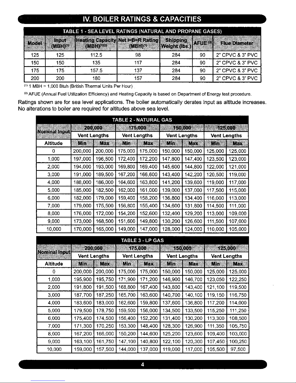
c_)1MBH = 1,000 Btuh(British ThermalUnits PerHour)
M
284 90
284 90
284 90
284 90
2" CPVC & 3" PVC
2" CPVC & 3" PVC
2" CPVC & 3" PVC
2" CPVC & 3" PVC
(2)AFUE (AnnualFuel Utilization Efficiency) and Heating Capacity is based on Department of Energytest procedure.
Ratings shown are for sea level applications. The boiler automatically derates input as altitude increases.
No alterations to boiler are required for altitudes above sea level.
Altitude
0
1,000
2,000
3,000
4,000
5,000
6,000
7,000
8,000
9,000
10,000
Vent Lengths
200,000 200,000
197,000 196,500
194,000 193,000
191,000 189,500
188,000 186,000
185,000 182,500
182,000 179,000
179,000 175,500
176,000 172,000
173,000 168,500
170,0001 165,000
Vent Lengths
175,000 175,000
172,400 172,200
169,800 169,400
167,200 i 166,600
164,6001 163,800
162,000 161,000
159,400 158,200
156,800 155,40C
154,200 152,600
151,600 149,800
149,000 147,000
Vent Lengths
150,000 150,000
147,800 147,400
145,600 144,800
143,400 142,200
141,2001 139,600
139,000 137,000
136,800 134,400
134,600 131,800
132,400 129,200
130,200 126,600
128,000 124,000
Vent
125,000
123,500
122,000
120,500
119,000
117,500
114,500
113,000
111,500
110,000
125,000
123,000
121,000
119,000
117,000
115,000
113,000
111,000
109,000
107,000
105,000
Altitude
0
1,000
2,000
3,000
4,000
5,000
6,000
7,000
8,000
9,000
10,000
200,000
195,900
191,800
187,700
183,600
179,500
175,400
171,300
167,200
163,100
159,000
200,000
195,750
191,500
187,250
183,000
178,750
174,500
170,250
166,000
161,750i
157,500
175,000
171,900
168,800
165,700
162,600
159,500
156,400
153,300
150,200
147,100
144,000
175,000
171,200
167,400
163,600
159,800
156,000
152,200
148,400
144,600
140,800
137,000
150,000
146,900
143,800
140,700
137,600
134,500
131,400
128,300
125,200
122,100
119,000
150,000
146,700
143,400
140,100
136,800
133,500
130,200
126,900
123,600
120,300
117,000
125,000
123,050
121,100
119,150
117,200
115,250
113,300
111,350
109,400
107,450
105,500
125,000
122,250
119,500
116,750
114,000
111,250
108,500
105,750
103,000
100,250
97,500
These low pressure gas-fired hot water boilers are design certified by CSA International, for use with
natural and propane gases. The boilers are constructed and hydrostatically tested for a maximum work-
ing pressure of 50 psig (pounds per square inch gauge) in accordance with A.S.M.E. (American Society
of Mechanical Engineers) Boiler and Pressure Vessel Code, Section IV Standards for heating boilers.
The Boilers are certified in accordance with ANSI (American National Standards Institute) Z21.13
standards as gas-fired, direct vent, condensing, hot water boilers.
The Heating Capacity indicates the amount of heat available after subtracting the losses up the stack.
Most of this heat is available to heat water. A small portion is heat loss from the jacket and surfaces of
the boiler, and it is assumed that this heat stays in the structure. The Net I=B=R Rating represents the
portion of the remaining heat that can be applied to heat the radiation or terminal units (i.e. finned tube
baseboard, cast iron radiators, radiant floor, etc.). The difference between the Heating Capacity and the
Net I=B=R Rating, called the piping and pickup allowance, establishes a reserve for heating the volume
of water in the system and offsetting heat losses from the piping. The Net I=B=R Ratings shown are
based on a piping and pickup factor of 1.15 in accordance with the I=B=R Standard as published by the
Hydronics Institute. The Net t=B=R Rating of the boiler selected should be greater than or equal to the
calculated peak heating load (heat toss) for the building or area(s) served by the boiler and associated hot
water heating systems. The manufacturer should be consulted before selecting a boiler for installations
having unusual piping and pickup requirements.
Complete all of _e following prior to installing the boiler.
This boiler product is a gas-fired, direct vent, con-
densing boiler and must be installed in accordance
with all applicable federal, state and local building
codes including, but not limited to the following:
United States - Installation shall conform
with National Fuel Gas Code (NFPA-54/ANSI
Z223.1 - latest revision)
Canada - Installation shall be in accordance
with CSA-B149.1 and .2 installation codes.
• Check to be sure you have selected the boiler
with the proper capacity before continuing the in-
stallation. The I=B=R Rating of the boiler selected
should be greater than or equal to the calculated
peak heating load (heat loss) for the building or
area(s) served by the boiler and associated hot
water heating systems. See Section IV, "Boiler
Ratings and Capacities, "for more information.
• Heat loss calculations should be based on
approved industry methods.
Where required by the authority having jurisdiction,
the installation must conform to the American Soci-
ety of Mechanical Engineers Safety Code for Con-
trols and Safety Devices for Automatically Fired
Boilers, No.CSD-I.
The installation must conform to the requirements
of the authority having jurisdiction or, in the ab-
sence of such requirements, to the National Fuel
Gas Code, ANSI Z223.1 - latest revision.
Installers- Follow local regulations with re-
spect to installation of CO (Carbon Monox-
ide) Detectors. Follow maintenance recom-
mendations in this manual.
Before selecting a location for the boiler, the follow-
ing should be considered. Each boiler considered
for installation must be:
• Supplied with the correct type of gas (natural
gas or propane).
• Connected to a suitable combustion air intake pip-
ing system to supply the correct amounts of fresh
(outdoor) air for combus_on (max. leng_ 60').
• Connected to a suitable venting system to re-
move the hazardous products of gas combus-
tion (max. length 60').
• Connectedto a suitable hot water heating
system.
• Suppliedwitha suitableelectricalsupplyfor
allboilermotorsandcontrols.
• Connectedto a properlylocatedthermostat
oroperatingcontrol.(not includedwithboiler)
• Placedon level surface (mustNOT be in-
stalledon carpeting)
• Condensatedrainline must be pitched down
to floor drain or external condensate pump with
reservoir at ¼"per foot (wood frame or blocks
may be used to raise boiler).
1. Select a location which is level, central to the
piping systems served and as close to the vent
and air intake terminals as possible.
2. Accessibility clearances, if more stringent (i.e.
larger clearances) than required fire protection
clearances, must be used for the boiler installa-
tion. Accessibility clearances may be achieved
with the use of removable walls or partitions.
3. The boiler is approved for installation in clos-
ets and on combustible floors. This boiler shall
NOT be installed on carpeting.
the front where passage is required for cleaning or
servicing, inspection or replacement of any parts
that normally may require such attention. Allow at
least 24" at the front and left side and 8" at the top
for servicing. No combustible clearances are re-
quired to venting or combustion air intake piping.
5. Equipment shall be installed in a location
which facilitates the operation of venting and
combustion air intake piping systems as de-
scribed in this manual.
6. Advise owner of boiler to keep venting and
combustion air intake passages free of obstruc-
tions. Both the venting and combustion air intake
piping systems connected to the outdoors must
permit flow through the piping systems without
restrictions for the boiler to operate.
7. The boiler shall be installed such that the
automatic gas ignition system components are
protected from water (dripping, spraying, rain,
etc.) during operation and service (circulator re-
placement, control replacement, etc.).
8. The boiler must be located where ambient
temperatures (minimum possible room temper-
atures where boiler is installed assuming boiler
is not in operation and therefore contributes no
heat to the space) are always at or above 32°F
to prevent freezing of liquid condensate.
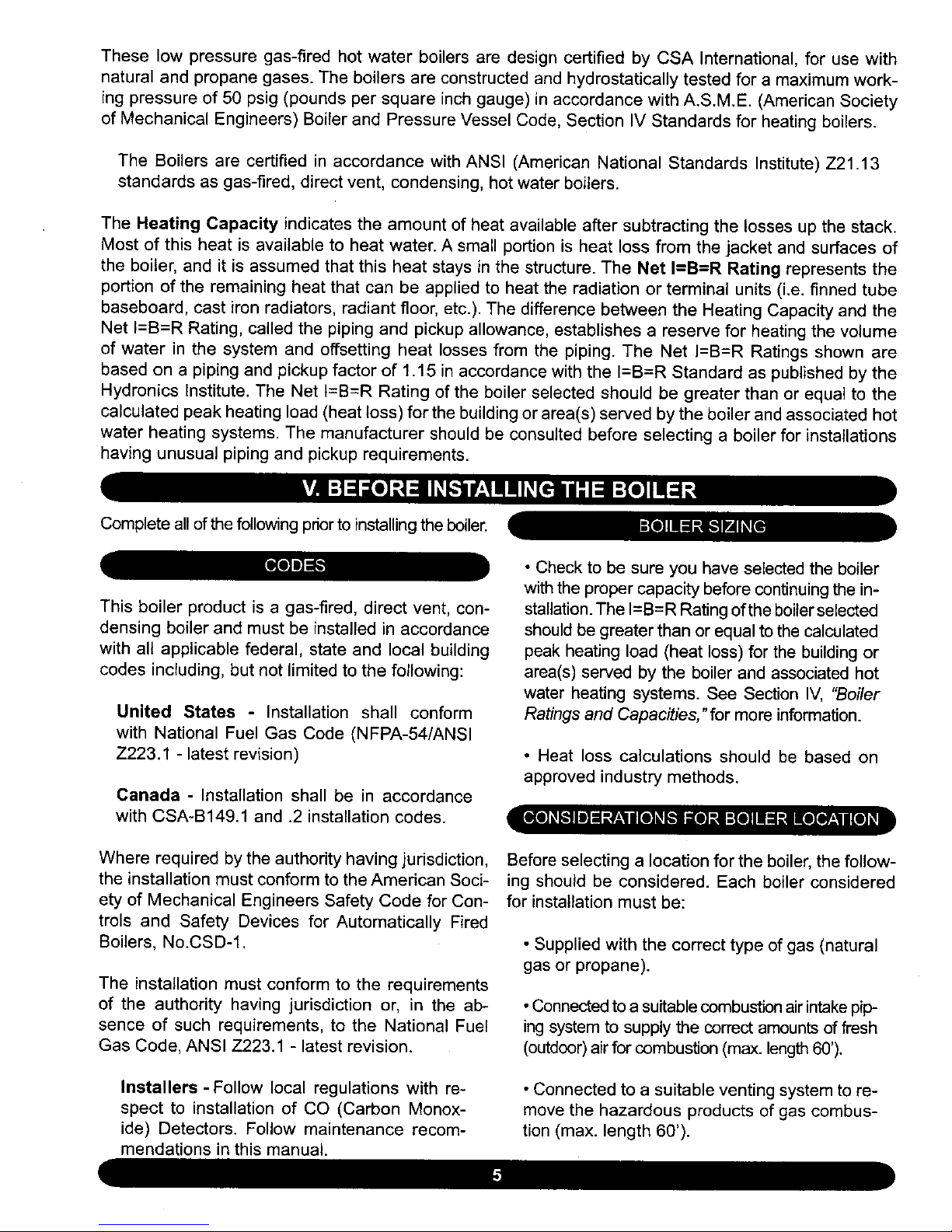
Top 1" 8"
Left Side 8" 24"
Right Side 1"
Base 1"
Front 0" 24"
Back 1"
IntakeNent
0"
Piping
_lear Boiler Hot
1"
Water Piping
All distances measured from the cabinetof the boiler.
4. The clearances shown in Table 4 indicate re-
quired clearances per CSA listing. A min. 1" clear-
ance must be maintained between combustible
construction and each of the right, top and back
surfaces of the boiler. A min. 8" clearance is re-
quired on the left side, to allow room for the inlet
air pipe. An 18" clearance must be maintained at
This boiler requires a dedicated direct vent system.
In a direct vent system, all air for combustion is
taken directly from outside atmosphere, and all flue
products are discharged to outside atmosphere.
ROOF VENT/INTAKE TERMINATIONS
i Figure 1 ]
Combustion air and vent pipe connections must
terminate together in the same atmospheric pres-
sure zone, either through the roof or sidewall (roof
termination preferred). See Figures 1 and 2 for re-
quired clearances.

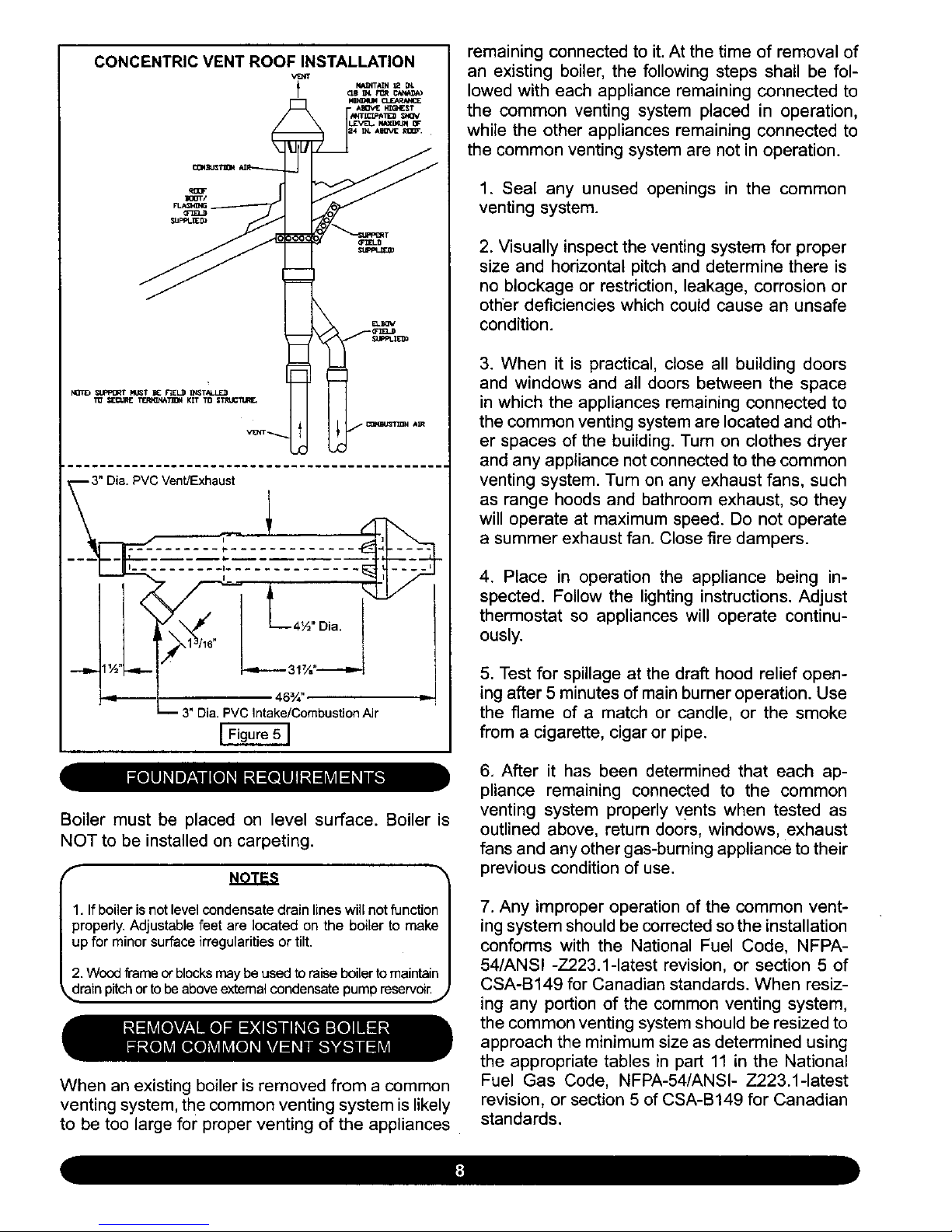
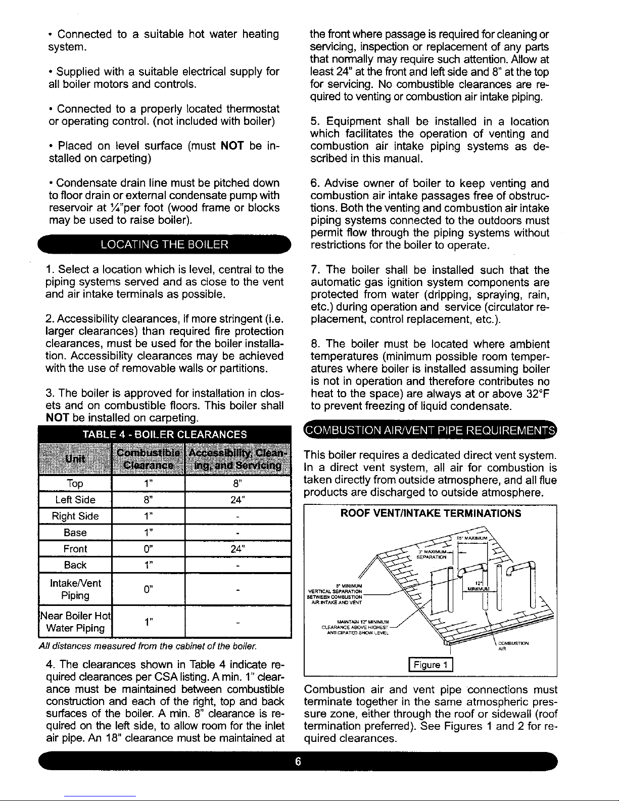
CONCENTRIC VENT ROOF INSTALLATION
, AIIOv_E_6NEST
3" Dia. PVC Vent/Exhaust !
-
! _1 46%" I,-
n 3" Dia. PVC Intake/Combustion Air
[ Figure 5 ]
remaining connected to it. At the time of removal of
an existing boiler, the following steps shall be fol-
lowed with each appliance remaining connected to
the common venting system placed in operation,
while the other appliances remaining connected to
the common venting system are not in operation.
1. Seal any unused openings in the common
venting system.
2. Visually inspect the venting system for proper
size and horizontal pitch and determine there is
no blockage or restriction, leakage, corrosion or
other deficiencies which could cause an unsafe
condition.
3. When it is practical, close all building doors
and windows and all doors between the space
in which the appliances remaining connected to
the common venting system are located and oth-
er spaces of the building. Turn on clothes dryer
and any appliance not connected to the common
venting system. Turn on any exhaust fans, such
as range hoods and bathroom exhaust, so they
will operate at maximum speed. Do not operate
a summer exhaust fan. Close fire dampers.
4. Place in operation the appliance being in-
spected. Follow the lighting instructions. Adjust
thermostat so appliances will operate continu-
ously.
5. Test for spillage at the draft hood relief open-
ing after 5 minutes of main burner operation. Use
the flame of a match or candle, or the smoke
from a cigarette, cigar or pipe.
Boiler must be placed on level surface. Boiler is
NOT to be installed on carpeting.
NOTES
1. Ifboiler is not level condensate drain lines will not function
properly, Adjustable feet are located on the boiler to make
up for minor surface irregularities or tilt,
2. Wood frame of blocks may be used to raise boiler to maintain
_drain pitch or to be above extemal condensate pump reservoir.J
When an existing boiler is removed from a common
venting system, the common venting system is likely
to be too large for proper venting of the appliances
6. After it has been determined that each ap-
pliance remaining connected to the common
venting system properly vents when tested as
outlined above, return doors, windows, exhaust
fans and any other gas-burning appliance to their
previous condition of use.
7. Any improper operation of the common vent-
ing system should be corrected so the installation
conforms with the National Fuel Code, NFPA-
54/ANSI -Z223.1-1atest revision, or section 5 of
CSA-B149 for Canadian standards. When resiz-
ing any portion of the common venting system,
the common venting system should be resized to
approach the minimum size as determined using
the appropriate tables in part 11 in the National
Fuel Gas Code, NFPA-54/ANSI- Z223.1-1atest
revision, or section 5 of CSA-B149 for Canadian
standards.

Theboiler should be placed to providethe most
directconnectionsto the combustionair,vent and
systempipingas possible.
Placecrated boiler as close to selectedlocation
aspossibleanduncrateboiler.Theuncratedboiler
maybemovedinto positionwithan appliancedol-
ly or 2-wheelhandtruck.The dolly or handtruck
shouldbe insertedunderthe right hand side of
theboiler.Itispossibletoslidethe boilerforashort
distanceonasmoothfloororsurface.
NuOTE: Refer to "Locating The Boiler" in Section V for re-_
ired clearances for servicing and maintenance. J
f
iA cAo.,-,o,AI
Copper supply and return piping must NOT be in-
stalled directly into aluminum boiler section castings
due to galvanic corrosion between dissimilar met-
als. Iron or steel bushings or pipe nipples should
be used between copper system piping and boiler
to make final connection to boiler. Also, the use of
dielectric unions is acceptable. The packaged boiler
is furnished with iron piping in the front boiler sec-
tion for the supply and return connections.
When the installation of the boiler is for a new heat-
ing system, first install all of the radiation units (pan-
els, radiators, baseboard, or tubing) and the supply
and return mains. After all heating system piping and
components have been installed, make final con-
nection of the system piping to the boiler.
Ahot water boiler installed above radiation level must
be equipped with a low water cut off device (included
with boiler). A periodic inspection is necessary, as is
flushing of float type devices, per low water cut off
manufacturers specific instructions.
DIAPHRAGM TYPE EXPANSION TANK PIPING
E_C_ T_f_ _VICE VAL_
--(_,_n[ VALOIS C_ FULL
PORT B_ VAL'_
_J TO_ATIC _R
V_. _/'_"X'/8"_F_t_i_O_J_'_i_°iN
.... ?ST _°_1_4 FC_ F_ WA_R
Figure 6 ]
Determine required system fill pressure, system de-
sign temperature, and system water content. Boiler
contains 2.6 gallons (U.S.). Size expansion tank ac-
cordingly. Consult expansion tank manufacturer for
proper sizing information. Connect properly sized
expansion tank (not furnished) as shown in Figure 6
for diaphragm type expansion tank. For diaphragm
type expansion tanks, adjust the tank air pressure
to match the system fill pressure. Install air vent
(fumished) as shown for diaphragm type expansion
tank system only. install make-up water connec-
tions as shown and per local codes. If a pressure
reducing valve is used, adjust to match the system
fill pressure. In connecting the cold make-up water
supply to the boiler, make sure that clean water sup-
ply is available. When the water supply is from a well
or pump, a sand strainer should be installed at the
pump.
RELIEF VALVE DISCHARGE PIPING
fPRESSUR[ REUEF0EVlC[
[FigureTI
The boiler is furnished with a relief valve and tem-
perature pressure gauge in the boiler parts bag. In-
stall vent retief valve as shown in Figure 7. Provide
¾" piping from the relief valve to a local floor drain,
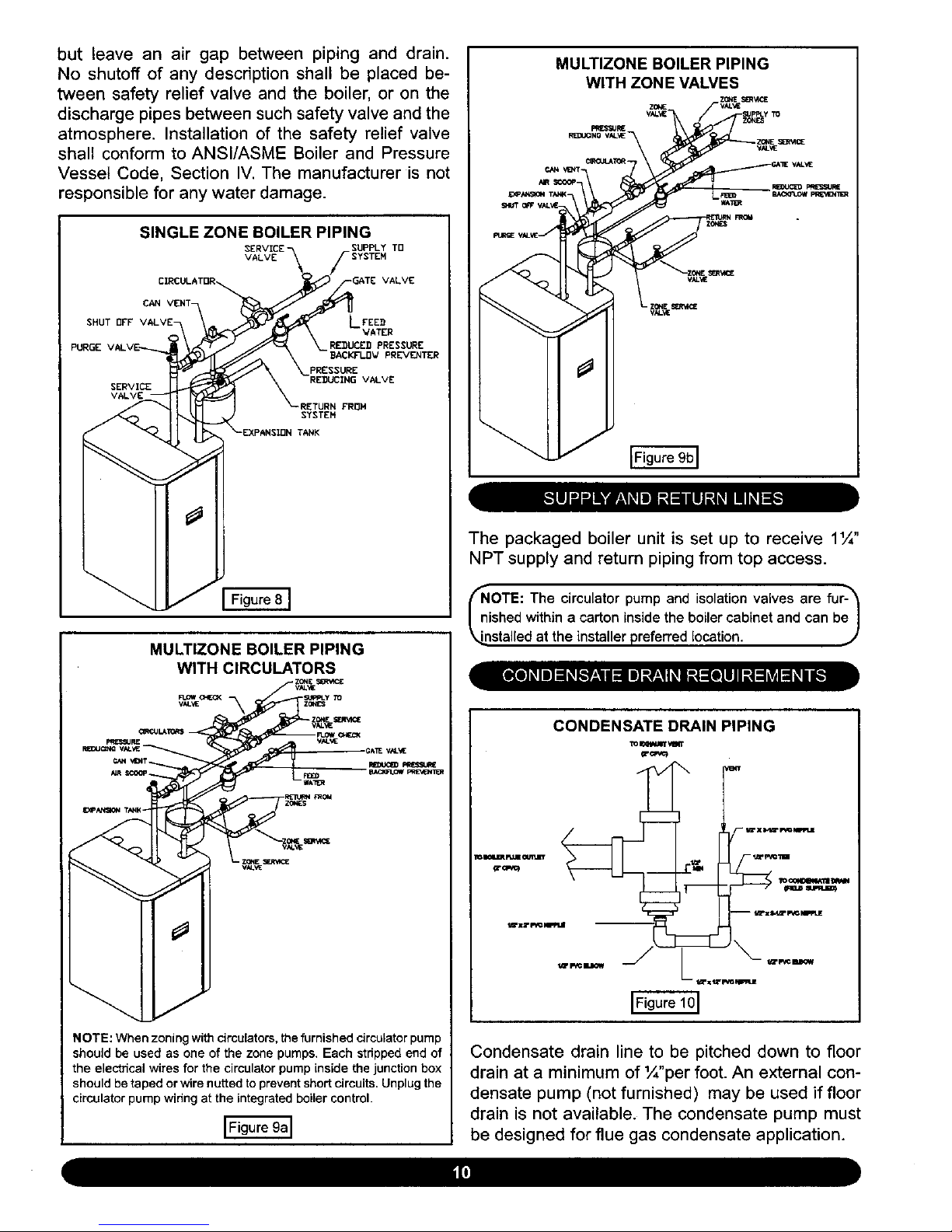
but leave an air gap betweenpiping and drain.
No shutoffof any descriptionshall be placed be-
tween safety reliefvalve and the boiler,or on the
dischargepipesbetweensuchsafetyvalveandthe
atmosphere.Installationof the safety reliefvalve
shall conformtoANSl/ASMEBoilerand Pressure
VesselCode, SectionIV.The manufactureris not
responsiblefor anywaterdamage.
SINGLE ZONE BOILER PIPING
SUPPLY TD
VALVE
VALVE
CAN VENT-
SHUT OFF LFEE_
VATER
PURGE RE_UCED PRESSURE
BACKFI.I]V PREVENTER
PRESSURE
SERVICE
RETURN FROH
SYSTEN
TANK
MULTIZONE BOILER PIPING
WITH CIRCULATORS
,GAE VAL_E
NOTE: When zoning with circulators, the furnished circulator pump
should be used as one of the zone pumps. Each stripped end of
the electrical wires for the circulator pump inside the junction box
should be taped or wire nutted to prevent short circuits. Unplug the
circulator pump wiring at the integrated boiler control.
MULTIZONE BOILER PIPING
WITH ZONE VALVES
The packaged boiler unit is set up to receive 11¼"
NPT supply and return piping from top access.
frNiOTE: The circulator and isolation valves fur-_
pump
are
shed within a carton inside the boiler cabinet and can beJ
/
_nstalled at the installer preferred location. J
CONDENSATE DRAIN PIPING
lo INWJI_ ,¢m't
Condensate drain line to be pitched down to floor
drain at a minimum of '/_"per foot. An external con-
densate pump (not furnished) may be used if floor
drain is not available. The condensate pump must
be designed for flue gas condensate application.

f
NOTES
1. Condensate trap is to be built in the field per Figure 10
2. Wood frame or blocks may be used to raise the boiler
to maintain drain pitch or to be above external condensate
pump reservoir.
3. There is a 115 volt AC receptacle provided on the service
switch junction box which.is located at the boiler right side, to
provide power for an external condensate pump (if needed).
,. j
The condensate trap is to be field installed as previ-
ously shown in Figure 10. Provided are ½" PVC fit-
tings for the condensate drain trap (assembled in the
field). The condensate drain is to be pitched down to
the floor drain at a minimum of 1¼,,per foot.
The ½" diameter schedule 40 PVC condensate
drain piping and pipe fittings must conform toANSI
standards and ASTM D1785 or D2846. Schedule
40 PVC cement and primer must conform to ASTM
D2564 or F493. In Canada, use CSA or ULC certi-
fied schedule 40 PVC drain pipe and cement.
A condensate pump with a reservoir (not furnished)
may be used to remove condensate to a drain line
(sanitary line) above boiler if a floor drain is not
available or is inaccessible.
ON INITIAL START UP THE CONDENSATE TRAP
MUST BE MANUALLY FILLED WITH WATER.
The following are the steps required to initially fill
the condensate trap for start up, these steps are
only required at the initial start up or if maintenance
requires draining of the condensate trap:
1. Pour about 1 cup of cold tap water into the
condensate trap vent.
2. Excess water should go through the conden-
sate drain line. Verify proper operation of the drain
line (and external condensate pump if used).
The boiler, when used in connection with a refrig-
eration system, must be installed so the chiller me-
dium is piped in parallel with the boiler with appro-
priate valves to prevent the chilled medium from
entering the boiler.
The boiler piping system of a hot water boiler con-
nected to heating coils located in air handling units
where they may be exposed to refrigerated air cir-
culation must be equipped with flow control valves
or other automatic means to prevent gravity circu-
lation of the boiler water during the cooling cycle.
/ibMPORTANT: To prevent damage to the gas_
urner and ensure proper operation of the unit, I
I installer must clean and remove all shavings from I
k_he interior of all PVC pipe used on the air intake.,,,/
For boilers connected to gas vents or chimneys, vent
installations shall be in accordance with part 7,Venting
of Equipment, of the National Fuel Gas Code, ANSI
Z223.1-1atest revision, CSA-B149.1 and B149.2, and
applicable provisions of the local building codes.
Provisions for combustion and ventilation air must
be in accordance with section 5.3, Air For Com-
bustion and Ventilation, of the National Fuel Gas
Code, ANSI Z223.1-1atest revision, CSA-B149.1
and B149.2, or applicable provisions of the local
building code.
outdoors through the combustion air intake pipe.
All flue products are discharged to the outdoors
through the vent pipe.
1. See Figures 1-2 in Section V, "Combustion Air
and Vent Pipe Requirements," for standard two-
pipe roof and sidewall terminations and Figures
3-5 (same section) for concentric vent termina-
tions (roof termination is preferred). Combus-
tion air and vent pipes must terminate together
in same atmospheric pressure zone as shown.
Construction through which vent and air intake
pipes may be installed is a minimum ¼" and max-
imum 24" thickness.
2. Combustion air and vent pipe fittings must con-
form to one of the following American National
Standards Institute (ANSI) and American Society
for Testing and Materials (ASTM) standards:
• D 1784 (schedule-40 CPVC)
These boilers require a dedicated direct vent sys-
tem. All air for combustion is taken directly from
• D1785 (schedule-40 PVC)

• D2665 (PVC-DWV)
• D2241 (SDR-21 and SDR-26 PVC)
• D2661 (ABS-DWV)
• F628 (schedule-40 ABS).
Pipe cement and primer must conform to ASTM
standards D2564 (PVC) or D2235 (ABS).
In Canada construct all combustion air and vent
pipes for this unit of CSA or ULC certified sched-
ule-40 CPVC, schedule-40 PVC, PVC-DWV or
ABS-DWV pipe and pipe cement. SDR pipe is
NOT approved in Canada.
3. Combustion air and vent piping connections
on boiler are 2", but must increase to 3". Due to
potential for flue gas temperatures over 155°1,
the first 5 feet of vent pipe must be CPVC (fur-
nished), the remaining vent pipe can be PVC.
If any elbows are employed within the first 2 ½'
feet of vent, they must be CPVC. Two 30" pieces
of 2" CPVC pipe and one 2" CPVC coupling are
furnished with the boiler. (Figure 11)
COMBUSTION AIR AND VENT PIPING
3 INCH INTAKE ANO
EXHAUST TERMINATqONS
2- By 3-TR ANS rllON tN
THE VERTICAL pOS ITION
EXHAUST TEE
(FURNISHEO}
2# (50.SMM) CPVC COUPLING
_-- (FURNISHED)
)_ 2" (50"BMM} CPVC vE NT PIPING
I __ (FUR NISHEO & REQUIR ED)
NOT IN
HORIZONAL
SECTION
Reduce the maximum vent length 5 feet per
each additional elbow.
4. Combustion air and vent piping to be pitched
back to boiler at minimum 1/,,,per foot from intake
and vent terminals so that all moisture in com-
bustion air and vent piping drains to boiler. Pipes
must be pitched continuously with no sags or low
spots where moisture can accumulate and block
the flow of air or flue gas. Combustion air and
vent pipes must be airtight and watertight.
5. Consideration for the following should be used
when determining an appropriate location for ter-
mination of combustion air and vent piping:
• Comply with all clearances required as
stated in paragraph 6 (below)
• Termination should be positioned where
vent vapors will not damage plants/shrubs,
air conditioning equipment, or siding on the
house.
• Termination should be positioned so that
it will not be effected by wind eddy, air born
leaves, snow, or recirculated flue gases.
• Termination should be positioned where it
will not be subjected to potential damage by
foreign objects, such as stones, balls, etc.
• Termination should be positioned where
vent vapors are not objectionable.
• Put vent on a wall away from the prevailing
winter wind. Locate or guard the vent to pre-
vent accidental contact with people or pets.
• Terminate the vent above normal snow-
line. Avoid locations where snow may drift
and block the vent. Ice or snow may cause
the boiler to shut down if the vent becomes
obstructed.
NOTE: The exhaust transition from 2" pipe to 3" pipe must_'_
e made in a vertical run. (Transition pieces not included.)_
6 ft. in length plus 60 ft. in length and up
four (4) 90° elbows to four (4) 90 ° elbows
The length of pipe is counted from the boiler jack-
et (air intake pipe) or from vent tee (vent pipe).
The first five feet of "Total Equivalent Length" of
vent pipe must be CPVC.
• Under certain conditions, flue gas will con-
dense, forming moisture, and may be corro-
sive. In such cases, steps should be taken
to prevent building materials at the vent from
being damaged by exhaust of flue gas.
6. The venting system shall terminate at least 3
feet above any forced air inlet (except the boiler's
combustion air inlet) within 10 feet. The venting
system shall terminate at least 12 inches from
any air opening into any building. The bottom
of the vent shall be located at least 12 inches

abovegrade.Terminationof the vent shall be
notless than 7 feet above an adjacentpublic
walkway.Theventterminalshallnotbeinstalled
closerthan3feetfromtheinsidecornerofan L
shapedstructure.Terminationoftheventshould
be kept at least 3 feet away fromvegetation.
Theventingsystemshall terminateat least 4
feethorizontallyfrom,andin no caseabove or
belowelectricmeters,gas meters,regulators,
andreliefequipment.
Ifmultipleterminationsareused,theremustbe
a minimumof 12 inches betweenthe exhaust
ofoneterminationandthe airintakeof the next
termination.SeeFigures1-3in SectionE5foril-
lustrations.
(_NOTE: All field installed vent pipe must be 3".
1. Attach combustion air intake piping to sup-
plied Fernco 2" coupling on CVI gas valve. At-
tach vent piping to furnished 2" CPVC vent tee
on draft inducer outlet.
(_NOTE:AII pipe joints are to be water tight.
2. Working from the boiler to the outside, cut
pipe to required length(s).
3. Deburr inside and outside of pipe. Remove all
chips and shavings.
4. Chamfer outside edge of pipe for better distri-
bution of primer and cement.
5. Clean and dry all surfaces to be joined.
6. Check dry fit of pipe and mark insertion depth
on pipe.
(_OTE: It is recommended that all pipes be cut, prepared, and_
re-assembled before permanently cementing any joint. ,J
7. After pipes have been cut and pre-assem-
bled, apply cement primer to pipe fitting socket
and end of pipe to insertion mark. Quickly apply
approved cement to end of pipe and fitting sock-
et (over primer). Apply cement in light, uniform
coat on the inside of socket to prevent buildup of
excess cement. Apply second coat.
8. While cement is still wet, insert pipe into sock-
et with a 1/, turn twist. Be sure pipe is fully in-
serted into fitting socket.
9. Wipe excess cement from joint. A continuous
bead of cement will be visible around perimeter
of a properly made joint.
10. Handle pipe joint carefully until cement sets.
11. Support combustion air and vent piping a mini-
mum of every 5 feet using pre-formed metal hang-
ing straps. Do not rigidly support pipes. Allow for
movement due to expansion and contraction.
_.NOTE: Rigid supports will cause excess noise in vent piping._
I2. Slope combustion air and vent pipes toward
boiler a minimum of 1¼,,per linear foot with no
sags between hangers.
13. Use appropriate methods to seal open-
ings where vent and combustion air pipes pass
through roof or side wall.
Minimum 4" w.c. 10" w.c.
Maximum 10" w.c. 14" w.c.
Please check fine pressure while unit is running.
The gas pipe to your boiler must be the correct size
for the length of run and for the total BTU per hour
input of all gas utilization equipment connected to
it. See Table 6 for proper size. Be sure your gas
line complies with local codes and gas company
requirements.
The boiler and its individual shutoff valve must be
disconnected from the gas supply piping system
during any pressure testing of that system at test
pressures in excess of ½ psig (3.5kPa).
The boiler must be isolated from the gas supply pip-
ing system by closing its individual manual shutoff
valve during any pressure testing of the gas supply
piping system at test pressures equal to or greater
than ½ psig (3.5kPa).

92,000 190,000 350,000 625,000
63,000 130,000 245,000 445,000
50,000 105,000 195,000 365,000
requirements, by the National Fuel Gas Code,
ANSI Z223.1- latest revision. In Canada, follow
the CAN/CGA B149.1 and .2 Installation Codes
for Gas Buming Appliances and Equipment.
2. Use pipe joint compound suitable for liquefied
petroleum gas on male threads only.
131,000 216,000
90,000 145,000
72,000 121,000 103,000 217,000
mlncludes Fittings (2_OutsideDiameter
flMPORTANT: The length of pipe or tubing should"_
be measured from the gas meter or propane sec-
_.ond stage regulator, j
Refer to Figure 12 for the general layout at the boil-
er. The gas line enters the boiler through the left
side panel.
GAS PIPING
CONNECTION
The boiler is equipped with a ½" NPT connection on
the gas valve for supply piping and 1/£ NPT ball cock
for manual shut off. The following rules apply:
3. Use ground joint unions.
4. Install a sediment trap upstream of gas con-
trols.
5. Use two pipe wrenches when making the con-
nection to the gas valve to keep it from turning.
6. Install a manual shutoff valve in the vertical
pipe about 5 feet above floor outside the boiler
jacket.
7. Tighten all joints securely.
8. Propane gas connections should only be
made by a licensed propane installer.
9. Two stage regulation should be used by the
propane installer.
10. Propane gas piping should be checked out
by the propane installer.
11. It is recomended to use a ½" union suitable
for natural and propane gas after the ball cock to
facilitate service on the unit.
After all connection have been made, check imme-
diately for leaks. Open the manual shutoff valve.
Test for leaks by applying soap suds (or a liquid
detergent) to each joint. Bubbles forming indicate
leak. CORRECT EVEN THE SMALLEST LEAK
AT ONCE.
WARNING
1. Use only those piping materials and joining
methods listed as acceptable by the authority
having jurisdiction, or in the absence of such

WARNING
All electrical work must conform to local codes as
well as the National Electrical Code, ANSI/NFPA-
70, latest revision, in Canada, electrical wiring shall
comply with the Canadian Electrical Codes, CSA-
C22.1 and .2.
The boiler, when installed, must be electrically
grounded in accordance with the requirements of
the authority having jurisdiction or, in the absence
of such requirements, with the National Electrical
Code, ANSI/NFPA-70, latest revision. In Canada,
electrical wiring shall comply with the Canadian
Electrical Codes, CSA-C22.1 and .2.
Run a 14 gauge or heavier copper wire from the
boiler to a grounded connection in the service pan-
el or a properly driven and electrically grounded
ground rod.
Prior to making any line voltage connections, ser-
vice switch at boiler should be in the off position
and the power turned off at the fuse box.
Run a 120 volt circuit from a separate over current
protection device in the electrical service entrance
panel.
(_NOTE: Use copper conductors only.
This should be a 15 ampere circuit. A service switch
has been pre-wired and located on the exterior
boiler jacket. See Figure 13 for diagram showing
location of service switch junction box and power
supply connection points. Connect black (hot) lead
from the power supply to either of the unused brass
screws on the service switch. Connect the white
(neutral) lead from the power supply to the white
screw on the service switch. Connect the green
(ground) lead from the power supply to the ground
(green) screw on the service switch. The recepta-
cle on the service switch is always powered regard-
less of whether the switch is on or off, and could be
used as a power supply for an external condensate
pump if one is used.
The thermostat location has an important effect on
the operation of your boiler system. BE SURE TO
FOLLOW THE INSTRUCTIONS INCLUDED WITH
YOUR THERMOSTAT.
Locate the thermostat about five feet above the
floor on an inside wall. It may be mounted directly
on the wall or on a vertical mounted outlet box. It
should be sensing average room temperature.
AVOID THE FOLLOWING:
• Dead Spots - corners; alcoves; behind
doors
• Cold Spots - concealed pipes or ducts;
stairwells - drafts; unheated rooms on the
other side of the wall
• Hot Spots - concealed pipes; fireplaces; TVs
or radios; lamps; direct sunlight; kitchens
Set heat anticipator at 0.7 amps. Connect 24 volt
thermostat leads to the two (2) yellow wires located
in service switch junction box, located on outer jack-
et of boiler. See Figure 12 for service switch junction
box and thermostat field wiring connections.
See Figure 14 for service switch junction box and
circulator pump field wiring connections. If the two
120 volt circulator wire terminals inside the junction
box are not used, please leave the two wire nuts to
prevent the short circuit.
f L.___ CAUTION _1 "_
abel atl wires prior to disconnection when ser- I
icing controls. Wiring errors can cause improp- I
r and dangerous operation. VERIFY PROPER I
PERATION AFTER SERVICING. J

SCHEMATIC WIRING CONNECTIONS
NOTE: If any of the original wire as supplied with this appliance must be replaced, it must be replaced with type 150°C Thermoplastic wire or its equivalent.
.%
24 VA¢
SR PC_3l_Ct _SFORM_R
SECONE_RY
W BK P_
TO I_N_ORM_R
G F_J_RY p6
p_
{_ pURCta
(NOTE: USE COP_ER COttOU_ORS ONLYI
LADDER WIRING DIAGRAM
120 VOLT POWER SUPPLy
(NOTE: USE COPPER COI_DUCTORS ONLy]
H%TI
C_N/OF F 8LK
SWITCH
LWCO
_-1 CASTING TEMpERATLJR E
/
SAFE_" SWITCH
(MANtJAL RESE_ tl
4K1 3K1
fl
DIFFERENTIAL
AIR PRESSLJRE O_
NWITCH (NO)
S_T AT
TNERMOSTAT
2)
CIRCULATOR FIELD WIRED
HOT SURFACE IGNITE R P12. 2 p6-2
P7-2
_7-3
p4-3
p10-2 P5-3
J;
P10-3
5K2
" I
120 VAC
SFORM_R
GAS VALVE
II ]_ I I {(
P3"5 I I P3-2
AIR LC_IC & riMERS
: P3.3 O Pt/RGE
HIGH LIN_T O FLAME
AQU_STAT
CONTROL 1013 10 CONTROL
: P34

This section provides a brief description of the key
controls and accessories found in this boiler.
See Section XVII, "Troubleshooting," in this instal-
lation manual for detailed sequences of operation
and troubleshooting procedures. See the separate-
ly provided "Repair Parts Manual"for locations of all
control components and accessories described.
The integrated Boiler Control (IBC) is a micro-
processor based controller for high efficiency gas
boilers that monitors all safety controls and which
controls the operation of the combustion air blow-
er, circulator pump, burner, and a combination hot
surface igniter/flame sensor. This controller is not
intended for use with a vent damper. This controller
is mounted on the control panel inside the boiler
and contains five diagnostic indicator lights.
The electronic 24 volt gas control valve contains a
1:1 gas/air pressure regulator to control gas flow to
the main burner of the appliance, is suited for both
natural and LP gas, and is rated in accordance with
ANSI Z21.21 - latest revision and and CGA-6.5-M95.
GAS VALVE
THROTTLE
VALVE
INLET
PRESSURE_
TAP"-
INLET
PRESSURE
CONNECTION
--OUTLET
HOLEX NOT RENOVE
THIS CAP
HEABER
the failure mode as a lack of flame signal. The IBC is
manually reset from lockout by either removing and
reestablishing the thermostat's call for heat, or by
turning the service switch off, then back on.
INDICATOR LIGHTS
The High LimitAquastat Control determines the maxi-
mum boiler water temperature and also provides a
means for protecting the boiler and heating system
from unsafe operating conditions which could dam-
age the boiler. The aquastat is mounted in the ½" NPT
control well and ¾" x ½" bushing on the top of the front
boiler section at the hot water outlet. The aquastat is
tied in with the IBC and is factory set at 180°F water
temperature. The high limit setpoint is field adjustable
and may be set anywhere between 100°F and 200°F.
The field setpoint adjustment for each installation de-
pends on heating system requirements. The aquastat
automatically resets when the boiler water tempera-
ture drops 20°F below the setpoint value. This reset
value can be field adjusted within a range of 5-30°E
NOTE: The maximum setpoint of the aquastat must not_
xceed 200°F. .)
The 120 volt Hot Surface Igniter heats up to 1800°F
to initiate combustion of the gas in the burner. The
igniter is mounted next to the burner through the
gas/air mixer. The igniter also serves as a means
for proving the main burner flame by flame rectifica-
tion. In the event of a lack of flame signal on three
consecutive trials for ignition, the IBC will lockout.
The "Valve" and "Flame" diagnostic indicator lamps
(lamps "D" and "E" in Figure 16) will blink indicating
In the event of lack of or loss of water in the boiler,
the Casting Temperature Safety Switch (230°F set-
point) installed on the top of the aluminum boiler
section behind the supply piping shuts offthe boiler
by shutting off power to the Integrated Boiler Con-
trol (IBC) and causes the Power Indicator Light to
go out. This fault requires manual reset of the cast-
ing temperature safety switch to restart the boiler.
Verify that the boiler is properly filled with water be-
fore resetting this switch.

,_ WARNING
The diaphragm type differential pressure switches
are connected by vinyl tubing to the gas valve and
the air inlet connection on the negative side and
the sight glass adapter on the positive side. The
pressure switches monitor air flow by sensing the
differential pressure measured in inches of water
(" w.c.). The factory settings on these switches are
0.5" w.c. on the normally open switch and 3.5" w.c.
for the normally closed switch. See Section XVI,
"Detailed Sequence of Operation," for details on
the operation of the diferential pressure switches.
The blower provides a means for pushing combus-
tion air into and through the mixer, the bumer, the flue
ways of the cast aluminum boiler section before being
discharged through the vent piping to the outdoors.
Every forced hot water system requires at least one
circulating pump. The circulating pump imparts the
necessary energy to move the water through the
closed loop supply and return piping systems, termi-
nal heating equipment (i.e., finned tube radiators, etc.)
and back through the boiler for reheating. To provide
the required hot water flow rates, the circulator pump
must be properly sized to overcome frictional losses
(usually measured in feet of water, also referred to
as "pump head loss") of the supply and retum piping
systems and boiler. The circulator pump is fumished
in a carton within the boiler cabinet. The circulator(s)
should always be located on the downstream (i.e.,
"pumping away") side of the expansion tank.
The manual drain valve provides a means of draining
the water in the heating system, including the boiler and
hot water supply and return piping systems installed
above the drain valve. This drain valve is installed in
the ¾" tapping at the bottom of the boiler. Any piping in-
stalled below the elevation of this drain valve will require
additional drain valves to be installed at low points in the
piping systems in order to drain the entire system.
Each boiler must have a properly sized and installed
American Society of Mechanical Engineers rated pres-
sure relief valve. Water expands as it is heated by the
burner/boiler sections. If there is no place for the water
to expand its volume, (i.e., a properly sized and prop-
erly functioning expansion tank) pressure on the inside
of the boiler and heating system will increase. The fur-
nished relief valve will automatically open at 30 psig
pressure te relieve the strain on the boiler and heating
system from the increasing pressure. The pressure re-
lief valve discharge must be piped with the same size
as the valve discharge opening to an open drain, tub
or sink, or other suitable drainage point not subject to
freezing, in accordance with A.S.M.E. specifications.
Failure to provide the pressure relief valve with piping
as herein described may cause water damage and/or
serious bodily injury. The boiler manufacturer is net re-
sponsible for any water damage or personal injury.
This boiler is equipped with a blocked vent safety shutoff
means, which shuts off the main bumer gas in the event
that the flow of combustion products through the flue-
ways is reduced. The Integrated Boiler Control will have
to be manually reset in the event of three consecutive
attempts for ignition that are halted by a blocked vent.
In the event of blocked vent, enough air will not be avail-
able to support combustion, and the boiler control will
lockout due to loss of adequate air flow (arcer 3 trials
for ignition). The "Purge" diagnostic indicator lamp (lamp
"B" in Figure 16) will blink indicating the failure mode as
a lack of adequate air flow. The IBC is manually reset
from lockout by either removing and reestablishing the
thermostat's caUfor heat, or by tuming the service switch
off, then back on. If the boiler cannot be restored to nor-
mal operating condition by resetting the control, contact
a qualified service agency to check heat exchanger
flueways for blockage.
This unit is equipped with a Low Water Cut Off con-
trol that protects against dry firing. This control pro-
vides burner cut off if there is an unsafe water loss,
which can result from a broken or leaking radiator,
pipe, or boiler. A water/glycol mixture up to 50% con-
centration may be used with the Low Water Cut Off.
For installations where there is no floor drain or other
appropriate drainage available to receive condensate
from the boiler, an extemal float activated condensate
pump with integral sump (supplied by others)is required.
The condensate pump can be piped to a remote tie in
point to a sanitary sewer system. For this application,
the boiler must be installed so that proper pitch of piping
to the extemal condensate reservoir (sump) can be ac-
complished. Use wood frame or blocks (not factory sup-
plied) to raise boiler as required for proper installation.

1. Consultlocalwater treatmentspecialistfor wa-
ter treatmentrecomendationsif yourwaterpH lev-
elsarebelowof 7.0orhardnessisabove7 grains
hardness.
a.This boileris designedfor use ina closed
hydronicheatingsystemONLY!
b.Excessivefeedingoffreshmake-upwater
to the boiler may lead to premature failure of
the boiler sections.
2. Use clean fresh tap water for initial fill and peri-
odic make-up of boiler.
a. A sand filter must be used if fill and make-
up water from a well is to be used.
b. Consideration should be given to cleaning
the heating system, particularly in retrofit sit-
uations, where a new boiler is being installed
in an older piping system.
c. In older systems, obviously discolored,
murky, or dirty water, or a pH reading below
7, are indications that the system should be
cleaned.
d. A pH reading between 7 and 8 is preferred.
3. Antifreeze, if needed, must be of a type specifically
designed for use in closed hydronic heating systems
and be compatible with type 356 T6 aluminum at op-
erating temperatures between 20°F and 250°F.
a. Use of antifreeze must be in accordance
with local plumbing codes.
b. Pure glycol solutions are very corrosive,
therefore hydronic system antifreeze typi-
cally contains corrosion inhibitors. Different
brands of hydronic system antifreeze contain
different types of corrosion inhibitors. Some
brands have corrosion inhibitors that break
down more rapidly or become ineffective at
higher temperatures when used with alumi-
num. This could lead to premature failure of
the aluminum boiler. Consult the antifreeze
manufacturer on the compatibility of their
product with aluminum.
c. Follow the antifreeze manufacturer's in-
structions on determining proper ratio of an-
tifreeze to water for the expected low tem-
perature conditions, and for maintaining the
quality of the antifreeze solution from year to
year. Improperly maintained antifreeze solu-
tions will gradually lose their ability to protect
the aluminum boiler from corrosion.
d. The recommended premixed antifreeze
solution is INTERCOOL NFP-50. This
product is sold direct to distributors by the
antifreeze manufacturer. Please contact In-
terstate Chemical Company, New York Cus-
tomer Service at 1-800-422-2436 or your dis-
tributor for more information.
Use of an alternate manufacturer's premix
antifreeze is acceptable if the product speci-
fications are comparable with those of the
recommended premix antifreeze and the an-
tifreeze is compatible with type 356 T6 alu-
minum. Use of incompatible antifreeze could
damage the heat exchanger and will void the
product warranty.
The antifreeze must be maintained per the
specifications of the manufacturer. Failure to
do so will result in the warranty being voided.
Follow the antifreeze manufacturer's instruc-
tions on determining the proper ratio of an-
tifreeze to water for the expected low tem-
perature conditions and for maintaining the
antifreeze solution from year to year.
e. DO NOT USE AUTOMOTIVE ANTIFREEZE,
as the type of corrosion inhibitors used will coat
the boiler's heat transfer surfaces and greatly re-
duce capacity and efficiency.
f. Use of antifreeze in any boiler will reduce
heating capacity by as much as 10-20%,
due to differing heat transfer and pumping
characteristics. This must be taken into con-
sideration when sizing the heating system,
pump(s) and expansion tank. Consult anti-
freeze manufacturer's literature for specific
information on reduced capacity.
g. Water content of the boiler is 2,6 gallons
(10 liters).

Refer to the appropriate diagrams in Section VII,
"Near Boiler Piping," for more information.
1. Close all zone service valves on the supply
and return piping. Open the feed valve and fill
boiler with water. Make sure air vent is open.
Hold relief valve open until water runs air free for
five seconds to rapidly bleed air from boiler, then
let the relief valve snap shut.
2. Open the zone service valve on the
pipe for the first zone. Open the purge valve
on the first zone. Feed water will fill the zone,
pushing air out the purge valve. Close the purge
valve when the water runs air free. Close the
zone service valve.
3. Repeat step 2 for all remaining zones.
4. Open all service valves. Any air remaining
trapped in the return lines between the service
valves and the boiler will be pushed towards the
air vent when the boiler is placed in operation.
5. Inspect piping system. Repair any leaks im-
mediately.
4. Open the expansion tank service valve and
the tank vent. Fill the tank to the proper level
and close the tank vent. Remove the handle
from the expansion tank service valve so the
homeowner doesn't accidentally close it.
5. Open all service valves. Any air remaining
trapped in the return lines between the service
valves and the boiler will be pushed towards the
expansion tank when the boiler is placed in op-
eration.
6. Inspect piping system. Repair any leaks im-
mediately.
OTE: DO NOT use stop leak compounds. Leaks in"_
readed connections in the aluminum boiler sections mus._t I
e repaired immediately. Aluminum threads will not seal I
emselves. J
(_ READ BEFORE OPERATING APPLIANCE ,,_
1. This appliance does not have a pilot. It is
equipped with an ignition device which automat-
ically lights the burner. Do NOT try to light this
burner by hand.
2. Before operating smell all around the appli-
ance area for gas. Be sure to smell next to the
floor because some gas is heavier than air and
will settle to the floor.
Refer to the appropriate diagrams in Section VII,
"Near Boiler Piping," for more information.
1. Close all zone service valves on the supply
and return piping and close the expansion tank
service valve. Drain expansion tank. Open the
feed valve and fill boiler with water. Hold relief
valve open until water runs air free for five sec-
onds to rapidly bleed air from boiler, then let the
relief valve snap shut.
2. Open the zone service valve on the
pipe for the first zone. Open the purge valve
on the first zone. Feed water will fill the zone,
pushing air out the purge valve. Close the purge
valve when the water runs air free. Close the
zone service valve.
3. Repeat step 2 for all remaining zones.
3. Use only your hand to turn the gas shut off
valve. Never use tools. If the valve will not turn
by hand, do not try to repair it, call a qualified
service technician. Force or attempted repair
may cause fire or explosion.
4. Do not use this appliance if any part has been
under water. Immediately call a qualified ser-
vice technician to inspect the appliance and to

replace any part of the control system and any
gas control which has been under water.
Safe lighting and other performance criteria were
met with the gas manifold and control assembly
provided on the boiler when the boiler underwent
tests specified in ANSI Z21.13-latest revision.
1. STOPI Read the safety information above be-
fore operating this appliance.
2. Set the thermostat to the lowest setting.
3. Turn off all electrical power to the appliance.
4. This appliance does not have a pilot. It is
equipped with an ignition device which automat-
ically lights the burner, Do NOT try to light this
burner by hand.
5. Remove the front jacket panel.
6. Turn off the gas shut off valve. Valve handle
should be perpendicular to the gas pipe.
7. Wait five minutes for any gas to clear. Then
smell for gas, including near the floor. If you smell
gas, STOP! Follow instructions under "What To
Do If You Smell Gas" (previous page). If you do
not smell gas, go to the next step.
8. Turn the gas shut off valve to the "On" posi-
tion. The handle on the valve should be parallel
to the gas pipe.
9. Replace the front jacket panel.
10. Turn on all electrical power to the appliance.
11, Set thermostat to desired setting.
12, If the appliance will not operate, follow the
instructions in "To Turn Off Gas To Appliance"
(below) and call your service technician or gas
supplier.
1. Set the thermostat to the lowest setting.
2. Turn off all electric power to the appliance if
service is to be performed.
3. Remove the front jacket panel.
4. Turn gas shut off valve off. Handle should be
perpendicular to the gas pipe.
5. Replace the front jacket panel.

ThesequencecanbefollowedviathediagnosticindicatorlampsontheUT1013-10integratedboiler
controlin Figure16(SectionXI),Thisisthenormalsequenceofoperation.A moredetailedsequence
ofoperationcontainingpotentialfaultscanbefoundinthe servicehintssection.
(1) Lamp A is illuminated,indicating that the integrated control isreceiving
24 volts and is in standby waiting for the thermostat to call for heat.
(2) Thermostat calls for heat, energizing the system circulator.
(3) Integrated boiler control performs self check of internal circuitry,
lasting approximately two seconds, and energizes the draft inducer.
(4) The draft inducer comes up to speed and establishes combustion
airflow, causing the normally open differential pressure air proving
switch contacts to close. When combustion airflow is proved, Lamp
B is illuminated indicating that the 15 second pre-purge cycle has
begun.
(5) After the pre-purge has completed, Lamp B is extinguished and
Lamp C is illuminated, indicating power is being delivered to the hot
surface igniter for the 20 second igniter warm-up period. The bright
yellow-orange glow of the hot surface igniter can be observed through
the observation porLon the boiler.
(6) After the igniter warm-up period the integrated boiler control
energizes the gas valve, initiating a 6 second trial for ignition mode
which is indicated by the illumination of Lamp D. Two seconds later,
Lamp C will extinguish when the integrated boiler control stops
sending power to the hot surface igniter.
(7) A low level illumination of Lamp E indicates the initiation of flame
proving. During the last 2 seconds of the trial for ignition mode, main
burner flame is proven by flame rectification through the hot surface
igniter, providing a flame signal that is relayed to the integrated boiler
control, fully illuminating Lamp E.
(8) The thermostat ends its call for heat, causing the integrated boiler
control to de-energize the gas valve and system circulator. Lamp
D is extinguished while the unit enters the 30 second post purge
mode, indicated by the illumination of Lamp B. Lamp E will remain
illuminated as the remainder of the gas in the blower is burned off
(approximately 2 seconds). During post purge the blower remains
powered and clears out any residual products of combustion.
(9) After the post purge mode the draft inducer is de-energized and
the unit goes into standby mode until the next call for heat from the
thermostat.
A. •
B. O
C. O
D. O
E. O
A. •
B. •
C. O
D. O
E. O
A. •
B. O
C, •
D. O
E. O
A. •
B. O
C. •
D. •
E. O
A. •
B. O
C. O
D. •
E. •
A. •
B. •
C. O
D. O
E. O
A. •
B. O
C. O
D. O
E. O
NOTE: The first one or two cold starts may be rough due to the gas line not being completely purged of air, causing low firing
rate and high excess air levels.

Operate the boiler and verify that all vent/air intake
connections are gastight and watertight. Repair
any leaks immediately.
test for operation as outlined by the control manu-
facturer. Burner should be operating and should go
off when controls are tested. When safety controls
are restored, burner should reignite.
Vedfy that all connections are watertight, and that con-
densate flows freely. Repair any leaks immediately.
Verify that all connections are watertight. Repair
any leaks immediately.
1. Turn off manual gas shut off valve.
2. Set thermostat to call for heat.
3. Boiler begins normal sequence of operation.
4. After approximately 30 seconds (pre purge
and igniter warm-up period), lamp D illuminates,
indicating gas valve is powered.
5. After 4 seconds, gas valve closes, lamp D
goes out as integrated boiler control senses that
flame is not present.
6. To restart system, follow operating instruc-
tions in Section XII, "Start Up."
Set high limit differential to minimum setting. While
burner is operating, adjust setting on high limit con-
trol below actual boiler water temperature. Burner
should go off while circulator continues to operate.
Raise limit setting above boiler water temperature
and burner should reignite after pre purge and ig-
niter warm-up period. Set the high limit control to
the design temperature requirements of the sys-
tem. Maximum high limit setting is 200°F. Minimum
high limit setting is 100°F. Return high limit differen-
tial to original setting (20°F)
If the boiler is equipped with a low water cut off, a
manual reset high limit, or additional safety controls,
For a single thermostat connected to the yellow
thermostat lead wires in the furnished field wiring
junction box, the heat anticipator should be set at
0,7 amps. For other wiring configurations, refer to
the instructions provided by the thermostat manu-
facturer regarding adjustment of heat anticipator.
Cycle boiler with thermostat. Raise the thermostat
to the highest setting and verify boiler goes through
normal start up cycle. Lower thermostat to lowest
setting and verify boiler goes off.
Correct input rate is essential for proper and effi-
cient operation of the burner and boiler.
1. Determine the elevation at the installation
site.
2. See Table 2 in Section IV of this manual to
determine the correct approximate input rate for
the local elevation.
3. Obtain the yearly average heating value of the
local gas utility. At sea level elevation, it should be
approximately 1000 BTU per standard cubic foot.
4. Operate boiler for 5 minutes.
5. Turn off all other gas appliances, extinguish-
ing standing pilots where applicable.
6. At the gas meter, measure the time in sec-
onds required to use one cubic foot of gas.
7. Calculate the "input rate" according to the fol-
lowing formula:
Btuh input rate = 3600 x heatino value from steo 3
Time in seconds from step 6
8. The measured input rate should be within +0/-
2% of the input rating found in step 2. If not, see
"Adjustments and Checkout" on next page.

Set thermostatto desired roomtemperatureand
observeseveralcompletecycles to verify proper
operation.
Reviewallinstructionsshippedwiththisboilerwith
ownerormaintenanceperson.Instructionsmustbe
affixedonoradjacentto the boiler.Thencomplete
andsignthe "Installation and Checkout Certificate"
at the end of this manual.

Maintenance as outlined below can be performed
by the owner unless otherwise noted.
tings. Repair, if found. DO NOT use stop leak
compounds.
The acidic nature of flue gasses condensing on the
aluminum boiler sections will cause the formation
of aluminum oxide. This oxide formation is normal,
is generally uniform throughout the boiler sections,
and represents a negligible mass of aluminum that
is consumed by oxidation during the life of the boiler.
If left unchecked, this buildup may eventually cause
blockage of the flue gas passages in the boiler sec-
tions, reducing efficiency, and ultimately shutting
down the boiler due to lack of combustion air flow.
Regular service and maintenance by a qualified
service agency must be performed to assure
safe trouble free operation and maximum effi-
ciency. It is recommended to service the appli-
ance at least once every 12 months.
2. Check that boiler area is free from combustible
materials, gasoline, and other flammable vapors
and liquids.
3. Circulator pump and blower motor furnished
with boiler are permanently lubricated from the fac-
tory and require no further lubrication. Additional or
non-factory supplied pumps and/or motors should
be lubricated according to the pump and/or motor
manufacturer's instruction.
1. Schedule an annual service call by a qualified ser-
vice agency, which includes:
1. Check for and remove any obstruction to the flow
of combustion air or venting of flue gases.
2. Check that boiler area is free from combustible
materials, gasoline, and other flammable vapors
and liquids.
a. Examine flue passages between boiler sec-
tions, burner, and condensate lines, and clean if
necessary following the annual examination and
cleaning instructions in paragraph F (below).
b. Visually inspect venting and air intake system
for proper operation. If the vent or air intake show
any signs of deterioration or leakage, repair or
replace them immediately. Insure proper reas-
sembly and resealing of the vent and air intake
system.
c. Check for and remove any obstruction to the
flow of combustion air or venting of flue gases.
d. Follow instructions for "Placing Boiler In Op-
eration" in Section XII of this manual.
e. Follow "Checkout Procedures and Adjust-
ments" on previous page.
f. Visually inspect condensate drain line for prop-
er operation. Check for deteriorated or plugged
condensate drain line.
1. Remove jacket front and top panels and check for
piping leaks around relief valve and other fittings. If
found, contact a qualified service agency to repair.
DO NOT use stop leak compounds.
2. Test relief valve. Refer to valve manufacturer's in-
structions packaged with relief valve.
3. Visually inspect venting and air intake system for
proper function. If the vent or air intake show any
signs of deterioration or leakage, contact a qualified
service agency to repair or replace them immediate-
ly and to insure proper reassembly and resealing of
the vent and air intake system,
4. Visually inspect the PVC condensate drain pipe
for proper operation. If the drain pipe shows any
signs of blockage, leakage, or deterioration contact
a qualified service agency to clean, repair, or replace
it immediately.
5. Check air vent(s) for leakage.
g. Check all gasketed joints for leakage, and
tighten bolts or replace gaskets if necessary.
h. Remove jacket front and top panels and check
for piping leaks around relief valve and other fit-
Where low water cut offs are used, a periodic inspec-
tion of the low water cut off is necessary, including
flushing of float type devices. Refer to low water cut
off manufacturer's specific instructions.

1. Follow the instructions in "To Turn Off Gas ToAp-
pliance" in Section Xll.
i. Use a flexible handle nylon brush to loosen
sediment and aluminum oxide on all exposed
heating surfaces of boiler (see "Repair Parts
Manual" for diagram). Be sure that brush does
not get stuck in heat exhangeH
2. If heating system is to remain out of service dur-
ing freezing weather, and does not contain antifreeze,
drain system completely. If boiler will be exposed to
freezing temperatures, drain condensate lines. Oth-
erwise, do not drain system or boiler.
j. After brushing and rinsing, remove any remain-
ing loosened sediment using a shop vacuum
with a snorkel attachment.
k. Inspect burner for any foreign matter in the
flame ports or inside the burner. Any foreign
matter should be removed by blowing with com-
pressed air or vacuuming.
The following service procedures must be per-
formed only by a qualified service agency. Boil-
er owner should not attempt these procedures.
1. Before servicing, turn off electrical power to boil-
er at service switch. Close manual gas valve to turn
off gas supply to boiler.
2. Examine flue passages by removing blower as-
sembly from casting as shown in the separately
provided "Repair Parts Manual." The procedure for
examining and cleaning the burner is described be-
low.
Any buildup of sediment or aluminum oxide (white
powdery or flaky substance) in the flue passages
must be cleaned as follows:
a. Remove jacket front and top panels.
b. Confirm that manual gas valve is closed and
disconnect gas line to gas valve at union.
c. Disconnect wires to gas valve and igniter.
d. Remove air inlet assembly from gas valve.
e. Loosen but do not remove five nuts attaching
blower adapter assembly to boiler.
f. Remove two igniter screws and very carefully
remove the igniter. The igniter element is very
sensitive. Do not touch the igniter element
with your fingers or hands as oils or debris
will cause premature failure,
g. Remove five nuts and blower adapter assem-
bly. Remove burner and gaskets.
h. Aluminum oxide deposits are water soluble
and may be rinsed away with spraying or run-
ning water.
I. Reinstall burner and gaskets and position
blower adapter assembly over studs. Install five
nuts but do not tighten. Reinstall igniter and ig-
niter gasket and fasten with two screws. The ig-
niter element is very sensitive. Do not touch
the igniter element with your fingers or
hands as oils or debris will cause premature
failure Tighten five nuts holding blower adapter
assembly.
m. Connect gas line to gas valve; air inlet as-
sembly to gas valve (using 2" x 1½" flexible cou-
pling); pressure switch hose to gas valve and
air inlet assembly; 2" flexible coupling to boiler
exhaust port; igniter wires; and gas valve wires.
3. Visually inspect the condensate trap. Refer to re-
pair parts diagrams. Any foreign material or debris
that is visible in the condensate lines needs to be
cleaned out as described below.
a. Inspect for sediment or blockage.
b. Flush out with water or vacuum.
c. Follow the instructions under "Near Boiler Pip-
ing" in Section XII for filling condensate trap with
water.
4. Inspection of the flue connector requires the fol-
lowing steps. Refer to the "Repair Parts Manual"
for diagram.
a. Loosen clamp on draft inducer end of 2" flex-
ible coupling that connects vent tee to exhaust
port.
b. Inspect interior of vent tee. Any buildup of sed-
iment on the inside surface must be cleaned.
c. Reconnect the 2" flexible coupling to the draft
inducer outlet.

I POWER ON I
STAND BY
I THERMOSTAT I
CALLS FOR HEAT
CIRCULATOR
ENERGIZES THRU
2K1 CONTACTS
/
IBC SELF CHECK OF /
J
INTERNAL CIRCUITRY
1-2 SEC
IF MAIN BURNER DOES NOT PROVE
FL&ME IN 3 TRIALS, CONTROL
LOCKOUT, VALVE/FLAME LIGHT BLINKS,
RESET IS REQUIRED THIS PROBLEM IS A
RESULT OF NOT ESTABLISHING A FLAME SIGNAL.
CONTROL WILL ATTEMPT 2
ADDITIONAL IGNITION SEQUENCES
STARTING WITH PREPURGE
DRAFT JNDUCER I
ENERGIZES THRU
1KICONTACTS
IBC
WAITS FOR
UP TO 5 MINUTES
FOR AIR PRESSURE
SWITCH CONTACTS TO CLOSE
INDICATING FAN
SUCTION
PRESENT
_r
I
CONTROL LOCKOUT PURGE LIGHT I
BLINKS. RESET REQUIRED. CIRCULATOR
I
REMAINS ENERGIZED AS LONG AS
THERMOSTAT CONTINUES TO GALL FOR
HEAT
PURGE LIGHT 18ON, AIRFLOW PROVED.
DRAFT INDUCER RUNS FOR 15 SEC. PREPURGE
MAIN BURNER
BURNER PROVE
FLAME WITHIN
INITIAL TRIAL
FOR IGNITION
PERIOD?
J DURING THE LAST 2 SEC OF THE 6 SEC. IGNITION
TRIAL, MAIN BURNER FLAME IS PROVED BY FLAME
RECTIFICATION. A FLAME SIGNAL TO IBC GAS VALVE
REMAINS ENERGIZED. BOILER RUNS,
2 SEC INTO THE 6 SEC IGNITION TRIAL POWER
IS TURNED OFF TO THE HOT SURFACE IGNITER,
IGNITER LIGHT IS OFF.
GAS VALVE OPENS FOR 6 BEG. TRIAL FOR
IGNITION BLUE ORANGE GLOW OF THE BURNER
CAN BE SEEN THRU OBSERVATION PORT,
GAB VALVE ENERGIZED THRU 3K1 AND 4K1
CONTACTS. VALVE LIGHT IS ON.
PURGE LIGHT GOES OUT. HOT SURFACE IGNITER
POWERED THRU 5K1 5K2 CONTACTS FOR 20
SEC, IGNITER WARMUP BRIGHT YELLOW
ORANGE GLOW OF THE HOT SURFACE IGNITER
CAN BE OBSERVED THRU THE OBSERVATION
PORT iN FRONT OF BOILER SECTION JUST
ABOVE IGNITER. IGNITER UGHT IS ON.
NORMAL ]
OPERATION

SAFETY SEQUENCES DURING OPERATION
DRAFT INDUCER TEMPERATURE SAFETY SWITCH
IF DRAFT INDUCER TEMPERATURE REACHES
TEMPERATURE SAFETY SWITCH SETPOINT,
SAFETY SWITCH CONTACTS OPEN IMMEDIATEL_
CLOSING GAS VALVE (LIGHT GOES OUT).
POST PURGE AND SWITCHES OFF.
C,ROOLATORRUNS , . HA RMOSTATONCALL
WHEN TEMPERATURE SAFETY SWITCH CONTACTS
REMAKE BEFORE END OF CALL FOR HEAT, CON-
TROL GOES INTO NORMAL LIGHT-OFF SEQUENCE.
LOSS OF FLAME SIGNAL
IF AN ESTABLISHED FLAME SIGNAL IS LOST WHILE
CONTROL EXPECTS THAT THE BURNER ISOPERAT-
ING, CONTROL WILL IMMEDIATELY DE-ENERGIZE
GAS VALVE. VALVE AND FLAME MGHTS GO OUT.
I DRAFT INDUCER RUNS THROUGH 30 SECOND
POST PURGE. I
CONTROL WILL ATTEMPT TO RELIGHT BOILER
3 TIMES. IF FLAME IS NOT PROVEN, CONTROL
LOCKOUT - PROBLEM ESTABLISHING A FLAME
SIGNAL. VALVE LIGHT IS BLINKING.
LOSS OF COMBUSTION AIRFLOW
IF COMBUSTION AIRFLOW IS LOST WHILE BURNER
IS FIRING (DIFFERENTIALAIR PRESSURE SWITCH
CONTACTS OPEN) GAS VALVE WILL BE DE-ENER-
GIZED. VALVE AND FLAME LIGHTS GO OUT.
UTES FOR AIRFLOW TO BE RE-ESTABLISHED.
iF AIRFLOW DOES NOT RE-ESTABLISH CONTROL I
I LOCKOUT- PROBLEM WITH COMBUSTION AIR-
[ FLOW. PURGE L GHT BL NKS.
CASTING TEMPERATURE SAFETY SWITCH
IF BURNER OPERATES WHEN BOILER HAS NO WA- i
ER,ALUMINUM BOILER SECTIONS HEATUP RAPIDLY.I
÷
CASTING TEMPERATURE SAFETY SWITCH CON-
TACTS WILL OPEN, BREAKING 24 VOLT POWER
TO IBC. POWER INDICATOR LIGHT GOES OUT.
REQUIRES MANUAL RESET TO RECLOSE CON-
TACTS. POWER LIGHT GOES OUT.
HIGH LIMIT CONTROL
IF BOILER WATER TEMPERATURE REACHES
HIGH LIMIT (AQUASTAT) SETPOINT, HIGH LIMIT
N.C. CONTACTS OPEN IMMEDIATELY, CLOSING
GAS VALVE. VALVE AND FLAME LIGHTS GO OUT.
SECOND POST PURGE AND SWITCH OFF.
÷
WHEN HIGH LIMIT CONTACTS REMAKE BEFORE
END OF CALL FOR HEAT- CONTROL GOES INTO
A NORMAL LIGHT-OFF SEQUENCE.
CIRCULATOR PUMP
CIRCULATOR WILL BE ENERGIZED AS LONG AS
THERMOSTAT CALLS FOR HEAT DUR NG LOCKOUT.
÷
RECOVERY FROM ANY LOCKOUT REQUIRES
RESET, WHICH IS ACCOMPLISHED BY REMOVING
AND REAPPLYING THE THERMOSTAT CALL FOR
HEAT OR POWER TO CONTROL.

r
I
I
END OF NORMAL SEQUENCE OF OPERATION
I
THERMOSTAT ENDS CALL FOR HEAT. I
I
!
GAS VALVE AND CIRCULATOR PUMP ARE DE-ENER-
G ZED, VALVE AND FLAME L GHTS GO OUT.
BLOWER RUNS FOR 30 SECONDS POST PURGE,
PURGE LIGHT IS ON.
BLOWER IS DE-ENERGIZED AFTER 30 SECONDS,
PURGE LIGHT SHUTS OFF.
BOILER STAND BY FOR NEXT CALL FOR HEAT.

SERVICE HINTS
WARNING
IMPORTANT _'
1. In a reset from lockout condition, all electri-
cal meter readings at the gas control valve (24
VAC) must be taken within the trial for ignition
period.
2. If any component does not function properly,
make sure it is correctly installed and wired be-
fore replacing it.
3. Static electricity discharge can damage the Inte-
grated Boiler Control (IBC). Touch metal surface to
discharge static electricity before touching IBC.
4. The IBC cannot be repaired. If it malfunctions
it must be replaced.
5. Only trained, experienced service technicians
should service the IBC systems. See the chart
on the previous page titled "End of Normal Se-
quence of Operation" for a normal light-off se-
quence.
6. All controls are factory tested in the assembly
process and a defective control is generally the
least likely cause. If you suspect you have a de-
fective control, read through Section XVI, "Trou-
bleshooting," before you replace it.
7. It is extremely unlikely that two consecutive
controls are defective. If it seems to be hap-
pening, chances are that either there is nothing
wrong with the control or it is being damaged by
some other problem (for example, an electrical
k_.hort burning out a transformer.) .j
1. Before troubleshooting:
c. Make sure that gas is on at the gas me-
ter, at all appropriate manual shutoff valves,
and at the gas control valve.
d. Make sure that the thermostat is calling
for heat.
e. Check that wire connectors at the Integrat-
ed Boiler Control and at the originating con-
. trol are securely plugged in or connected.
f. Check that hoses are securely connected
and are not plugged or damaged.
2. Troubleshooting Tools:
a, Voltmeter to check 120 VAC and 24
VAC.
b. Continuity Tester.
c. Inclined Manometer or Pressure Gauge
with 0-4.0" range (0.01" scale) for measur-
ing suction pressures at pressure switch.
d. U-Tube Manometer or Differential Pressure
Gauge with 0-14" range (0.1" scale) for mea-
suring inlet and manifold gas pressures.
3. What is System Status?
A. Consult the "System Status'chart in Sex-
tion XVI, "Troubleshooting."
B. Refer to Figure 16 in Section XI of this
manual for the location of the diagnostic in-
dicator lamps on the boiler.
a. Make sure that circuit breaker is on or
fuse is okay ay electrical panel.
b. Make sure that service switch is on.

The differentialair pressure switch is a
safetydevicewhichwill preventthe boiler
from firing if there is an air intake, boiler
heatexchangerorventblockage.
1.Turnoffserviceswitch,or lowerther-
mostatsetting.
2. Removevinylcapsfrom Tee.
3.Installtestinglinesasshowntoinclined
manometerordifferentialpressuregauge
with the abilityto read 0.01"to at least
6.0"w.c.
4. Turn on service switch and set ther-
mostat to call for heat.
5. If manometer readings do not corre-
spond to the chart at right, check for
possible causes:
• Blockage or moisture in suction
lines to switch.
SERVICE HINTS
This diagram indicates the locations of the connection
points required to check the differential air pressure.
DIFFERENTIALAIR
PRESSURESWITCHES
TRANSPARENT WHITE
SILICONE HOSE
SIGHT GLASS
"ESTING
UNES
MANOMETER
OSE
GAS VALVE
• Blockage in air intake or vent
pipes.
• Undersized air intake or vent
pipes.
• Loose blower wheel on motor
shaft.
• Incorrect pressure switch or pres-
sure switch setpoint.
• Gas valve out of adjustment.
6. When pressure reading is proper and
the pressure switch is operating prop-
erly, remove testing lines and reinstall
vinyl caps to Tee and 3-way connector.
Not Running 0" 3.5" Closed
0.5" Open
Running With- 1.00" for Model 125 3.5" Closed
out Blockage 1.50" for Model 150 0.5" Closed
(Approximate
min. vent 1.50" for Model 175
lengths) 2.00" for Model 200
Running With ' Greater Than or Equal 3.5" Open
Blockage To Setpoints 0.5" Closed

SYSTEM STATUS
The indicator lights track the operating sequence. If the system locks out, the lights indicate the point in
the sequence of operation were lockout occurs. If this table does not readily provide the reason for boiler
malfunction or non-operation, refer to the following pages for more detailed troubleshooting procedures.
POWER
On
Off
Blinking
On
Off
PURGE
Blinking
On
IGNITER
Off
On
Off
VALVE
Blinking
On Bright
FLAME On Dim
Off
IBC is energized through 24 volt transformer.
IBC is not energized.
IBC receives more than 40 VAC.
IBC is energizing the draft inducer and air flow is proven.
Off during purge cycle - draft inducer is not powered on or air flow is not proven.
Off during igniter and run cycle - normal operation, purge cycle complete.
IBC is locked out. Problem could indicate false positive proof of air flow. Blocked vent,
intake air pipe, or flue way.
IBC is energizing igniter.
Igniter is not energized.
IBC is energizing gas control valve to open.
Gas control valve is closed.
IBC is locked out. Problem is flame has not been proven in three (3) ignition attempts.
May be due to broken igniter or lack of/low flame signal, or no gas.
Flame proven.
Checking for flame signal (during trial for ignition)
Flame unproven.
WARNING

I
TROUBLESHOOTING CHART #1
FALSE POSITIVE PROOF OF AIRFLOW. CHECK
AIR PRESSURE SWITCH CONTACTS,
IF CONTACTS ARE CLOSED WITH NO
AIRFLOW, REPLACE PRESSURE SWITCH.
CLOSED
GREEN POWER INDICATOR LIGHT IS I*,_Np_i_ {
ILLUMINATED OR THE IBC,
CHECK SYSTEM STATUS, IF LOCKED
OUTNOTE FAILURE MODE. WHICH
INDICATOR LIGHT IS BLINKING?
RESET SYSTEM BY TURNING SERVICE
SWITCH OFFTHEN ON. IF NOT
LOCKED OUT, SET THERMOSTAT TO
CALL FOR HE_T,
CIRCULATOR STARTS?
YES
IBC CHECKS NORMALLY OPEN AIR
PRESSURE SWITCH CONTACTS
OPEN
CHART3
CHART 2

TROUBLESHOOTING CHART #2
CHA_
I
l
CHECK THAT CIRCUIT BREAKER IS ON OR
FUSES ARE OK ATTHE ELECTRICAL PANEL
OK
CHECK THAT SERVICE SWITCH IS ON
,_DE
CHECK CASTING TEMPERATURE SAFETY
SWITCH. PUSH RESET BUTFON ON SWITCH.
CONTACTS OPEN (BUTTON UP) OR CLOSED
(BUTFON DOWN)?
lr CLOSED
CHECK WIRING TO IBC. 120 VAC BETWEEN
TERMINAL 1 AND 3 AT WIRING HARNESS
PLUG CN7?
YES
120 VAC BETWEEN TERMINALS 1 AND 3 AT
CONNECTOR CN3 ON IBC?
YES
120 VAC AT TRANSFORMER PRIMARY
TERMINALS?
YES
24 VAC AT TRANSFORMER SECONDARY
TERMINALS?
YES
I 24 VAC AT WIRING HARNESS PLUG CN2?
YES
REPLACE IBC
CHECK FOR 120 VAC BETWEEN TERMINALS
1 AND 3 AT CONNECTOR CN5 ON IBC?
YES
CHECK FOR 120 VAC AT CIRCULATOR
YES
REPAIR/REPLACE CIRCUL&TOR
I
I
IGPEN .I
"l
I
I NO
I NO ..r
I "L
NO
IN° i
J
I
t .° =1
I No ={
J
CHECK WATER LE'VEL IN BOILER. CHECK
FOR AIR TRAPPED IN TOP OF BOILER.
CONTACTS WILL NOT STAY CLOSED UNT;L
SOILER COOLS OFF.
REPLACE/REPAIR WIRING FROM SERVICE I
SWITCH TO iSC
I
REPLACE IBC I
REPAIR WIRING TO TRANSFORMER ]
REPLACE TRANSFORMER I
PUSH RESET BUTTON ON CASTING TEMP.
SAFETY SWITCH.
CHECK CONTINUITY OF CASTING TEMP
SAFETY SWITCH CONTACTS. CONTACTS
OPEN OR CLOSED?
CLOSED _ OPEN
REPLACE CAST. TEMP.
SAFETY SWITCH.
REPLACE/REPAIR WIRING FROM
TRANSFORMER TO ISC
REPLACE IBC
REPLACE/REPAIR W]R[NG FROM
IBC TO CIRCULATOR
I
I
I

BLOWER STARTS
YES
CHART 1
OPEN
TROUBLESHOOTING CHART #3
N_ CHECK FOR VAC N___
BETWEEN TERMINALS 1 AND 3
AT CONNECTOR CN4 ON 18C
YES
I CHECK FOR 120 VAC AT INO I
BLOWER LEADS ON WIRING
I-'1
HARNESS
YES
I REPAIR/REPLACE
BLOWER I
_P
I PURGELIGHTON? _'_
YES
]SO WAITS UP TO S
MINUTES FOR NORMALLY
OPEN AIR
PRESSURE SWITCH
CONTACTS TO CLOSE,
INDICATING BLOWER
SUCTION IS
PRESENT
REPLACE IBC ]
REPAIR/REPLCE
WIRING FROM IBC
TO BLOWER
PRESSURE SWITCH
CONTACTB
OPEN
ARE VENT PIPE AND AIR
INTAKE PIPE CLEAR
(NO BLOCKAGE)
YES
CHECK AIR
PRESSURE SWITCH PER
INSTRUCTIONS ON
FOLLOWING PAGES. ARE
SAMPLING LINES CLEAR
AND CONNECTED
PROPERLY?
,_YES
CHECK FLUE PASSAGES
IN BOILER PER
"MAINTENACE AND
CLEANING". ARE FLUE
___ CLEAN OUT VENT PIPE
AND/OR AIR INTAKE PIPE.
CHECK FOR SAGS OR
LOW SPOTS WHERE
CONDENSATE MAY
PUDDLE AND BLOCK
THE VENT
t__ CLEAN OUT BAMPUNG
LINES OR REPLACE
DEFECTIVE SWITCH
t__ CLEAN BOILER FLUE [
PASSAGES PER
MAINTENANCE AND
CLEANING INSTRUCTIONS
PASSAGES IN BOILER CLEAN?
YES
CHECK DRAFT INDUCER
MOTOR RPM, IS IT
3400-36007
YES
CHECK FOR BROKEN OR
LOOSE IMPELLER ON DRAFT
INDUCER AND REPLACE
BLOWER IF FOUND TO
BE BROKEN OR LOOSE
15 SECOND PRE PURGE COMPLETE.
PURGE LIGHT IS OFF. SIMULTANEOUSLY
IGNITOR LIGHT IS ON AS IGNITOR CIRCUIT
IS ENERGIZED.
REPLACE IBC
_. YEHSART4
REPLACE IBLOWER

CHART 3
YES
IGNITER/SENSOR WARMS _
UP AND GLOWS
YELLOW/ORANGE
DURING 20 SECOND
WARM UP
YES
,r
AFTER 20 SECOND
IGNITER WARM UP, GAS
VALVE IS ENERGIZED
VALVE LIGHT IS ON
2 SECONDS LATER POWER
IS REMOVED FROM
IGNITER/SENSOR
IGNITER LIGHT IS OFF
DOES MAIN BURNER
UGHT?
YES
TROUBLESHOOTING CHART #4
CHECK FOR 120 VAC _ I
BETWEEN TERMINALS 1
AND 2 AT CONNECTOR REPLACE tBC
CN1 ON IBC (DURING
IGNITER WARM UP)
YES
/
CHECK FOR 120 VAC AT I .
IGNITER/SENSOR LEADS _ REPAIR/REPLACE WIRING
ON WIRING HARNESS FROM IBC
(DURING IGNITER TO IGNITER/SENSOR
WARM UP)
YESI _ REPLACEIGNITER/SENSOR I
CHECK FOR 24 VAC
ACROSS TERMINALS MV
ON THE GAS CONTROL.
WHILE VALVE/FLAME
INDICATOR LIGHT IS ON
YES
CHECK FOR 24 VAC
ACROSS TERMINALS
CN6-2 AND CN6-5 ON
ISC, WHILE THE VALVE/
FLAME LED IS LIT
YES
REPAIR/REPLACE WIRING
BETWEEN IBC AND
GAS CONTROL
CHECK IF IGNITER/
SENSOR POSITION IS OK?
TiP SHOULD BE SLANTED
TOWARDS BURNER
YES
CHECK GAS SUPPLY
PRESSURE AT INLET
PRESSURE TAPPING ON
GAS CONTROL IS GAS
PRESSURE GRBATE R
THAN 40" WC?
YES
RESTORE IGNITER/SENSOR
TO CORRECT POSITION.
DO NOT RELOCATE
ARE ALL MANUAL
SHUT4OFFS IN THE GAS
SUPPLY LINE AND ON
THE GAS CONTROL IN
THE OPEN OR ON
POSITION?
YES
I CONTACT THE GAS UTILITYTO TURN THE GAS ON I
REPLACE IBC I
OPEN OR TURN ON ALL
MANUAL SHUTOFFS
CHART 5 CHART 5

TROUBLESHOOTING CHART #5
CHART4 CHART4
YES _ YES
POSSIBLY MIXTURE TOO LEAN!
CHECK GAS LINES DOWNSTREAM OF GAS
VALVE FOR BLOCKAGE.
ARE GAS LINES CLEAR?
IS GASNENTURI VALVE CORRECT SIZE?
SEE REPAIR PARTS DIAGRAM.
YES
POSSIBLY MITURE TOO RICH!
CHECK FLUE PASSAGES IN BOILER PER
"MAINTENANCE AND CLEANING". ARE
FLUE PASSAGES IN BOILER CLEAN?
,_YES
CHECK MIXER AND BURNER FOR
BLOCKAGE PER MAINTENANCE AND
CLEANING INSTRUCTIONS. ARE AIR
PASSAGES IN MIXER AND BURNER
CLEAN?
r
4,
CHECK AIR ORIFICE AT BURNER INLET
FOR CORRECT SIZE. SEE REPAIR PARTS
DIAGRAM. IS ORIFICE CORRECT SIZE?
CLEAN/REPLACE GAS LINES.
BE SURE TO USE CORRECT GASNENTURI VALVE SIZE.
CLEAN BOILER FLUE PASSAGES PER MAINTENANCE
AND CLEANING INSTRUCTIONS
CLEAN MIXER AND BURNER PER MAINTENANCE AND
CLEANING INSTRUCTIONS
REPLACE BURNER I
DOES MAIN BURNER
RUN UNTIL CALL FOR
HEAT ENDS OR HI
LIMIT AQUASTAT
CONTACTS OPEN?
CHART6
NO #1
NO#2
NO#3
7
* IF THE ANSWER IS NO.
CHOOSE THE APPROPRIATE
PATH (#1, #2, OR #3) BASED ON
SYMPTOMS SHOWN.
CHART 6 CHART 6
7
RUNS SMOOTHLY FOR ABOUT 6
SECONDS THEN SHUTS OFF.
INDICATES POOR FLAME SIGNAL.
CHECK IGNITER/SENSOR
POSITION. TIP SHOULD BE
SLANTED TOWARDS BURNER
,YES
CHECK FLAME SIGNAL >0.6uA?
CONSULT BOILER MFGR. FOR
SPECIFIC INSTRUCTIONS.
REQUIRES SPECIAL TOOLS.
,YES
REPLACEIBC
NO_ RESTORE
NO IGNITER/SENSOR
TO CORRECT POSITION.
DO NOT RELOCATE.
J
OXIDE COATING ON
IGNITER PREVENTING
FLAME SIGNAL.
REPLACE
IGNITERJSENOR,

TROUBLESHOOTING CHART #6
L
I
I
CHART5
YES
F
+
SET THERMOSTAT BELOW ROOM
TEMPERATURE TO END CALL FOR
HEAT
YES
DOES CIRCULATOR PUMP STOP?
¶LYES
VALE LIGHT IS OFF
_YES
DOES DRAFT BLOWER
STOP AFTER 30
SECOND POST PURGE?
_YES
SYSTEM OK
CHART 5
NO #3
CHART5
I NO #2
RUNS FOR 25-_ SECONDS,
THEN TURNS OFF.
CHECK FIRING RATE OF UNIT.
IS UNIT FIRING AT THE CORRECT RATE?
¶L YES
CHECK BURNER FOR ANY DETERIORATION
IN THE FLAME PORTS, ARE BURNER PORTS
IN GOOD CONDITION,
I
I
REPLACE GAS CONTROL. i
I
YES
CHECK GAS ORFICICE SIZE.
IS GAS ORIFICE SIZE CORRECT
CHECK REPAIR PARTS LIST
FOR CORRECT SIZE, IS GAS ORIFICE
CLEAR OF BLOCKAGE,
rYES
DOES THE UNIT USE LP GAS
NO
ADJUST RATE AS DESCRIBED IN THE
CHECK OUT PROCEDURE AND
ADJUSTMENT SECTION
OF THE MANUAL.
REPLACE WITH CORRECT
AIR BAFFLE.
_P
BOILER SHUTS OFF BEFORE END OF
CALL FOR HEAT ARE HI LIMIT
AQUASTAT CONTACTS CLOSED?
YES
SEE TROUBLESHOOTING PATH I
I
#2 ABOVE
YES
CHECK FLAME SIGNAL • 0.6uA? 'sO=INI-"__
CONSULT BOILER MFGR. FOR
SPECIFIC INSTRUCTIONS. REQUIRES
SPECIFIC TOOLS.
BOILER OFF ON HIGH LIMIT. IS
ACTUAL BOILER WATER TEMP.
GREATER THAN HI LIMIT SET POINT
MINUS 30°F CONTROL DIFFERENTIAL?
REPLACE BURNER
REPLACE IBC
NNNo_ REPLACE
AQUASTAT
OK
ARE THERMOSTAT CONTACTS OPEN? I_
_YES
I REPLASE,SCI
REMOVE WIRING HARNESS ___
CONNECTION CN9 FROM GAS
CONTROLDOESGASCONTROL
CLOSE?
_YES
REPLACE IBC I
REPLACE THERMOSTAT
REPLACE GAS CONTROL
I
I
I
I
I
I
I

f
Boiler Model Serial #
Date Installed
Measured BTU/HR Input
o Installation instructions have been followed
o Checkout procedure and adjustments performed
o Maintenance and Service issues reviewed with owner/maintenance person
o Installation booklet affixed on or adjacent to boiler
Installer (Company)
Address
Phone
Installer's Name
Signature

Gas-FiredDirectVent
Condensing
HOTWATERBOILER
Nowthat you have purchasedyour boiler,shoulda needeverexistfor repair
partsor service,simplycontactany SearsServiceCenter.Besureto provide
all pertinentfacts when you call or visit.
The model number of your Boilerwill be found on the model plateon the
side of the Boiler.
WHEN ORDERING REPAIR PARTS,ALWAYS GIVE THE FOLLOWING
INFORMATION:
,PARTNUMBER •PARTDESCRIPTION
,MODELNUMBER ,NAMEOFITEM
All parts listed may be ordered from any Sears Service Center.
If the parts you need are not stockedlocally,your order will be electrically
transmitted to a Sears RepairParts DistributionCenter for Handing.
WhenSears arranges the installation,you can be sure thejob isdone right.
We will arrange for professional workmanship.., and we'll take care of the
entire project. What's more,during installationyou get insured protection...
againstpropertydamageandalsoagainstaccidentstoworkmen.Allyouhave
to do is talk to your nearest Searsstoretoday for detailed information.
P/N 240004826K, Re'/. 1.1 [08,/05]
 Loading...