

Kenmore K90-150, K90-125, K90-200, K90-175 Owner's Manual
Gas-FiredDirectVent
Condensing
HOTWATERBOILER
• Installation
• Operation
• Maintenance
WARNING: Improper installation, adjustment, alteration, service
or maintenancecan cause injury or propertydamage. Referto this
manual. For assistance or information consult a qualified installer,
service agency or the gas supplier.

INSTALLATION MANUALAND OPERATING INSTRUCTIONS
PIN# 240004826K, Rev. 1.1 [08/05] • Printed in USA • Made In USA
I. Introduction ........................................................ 2
I1.Safety Symbols ................................................ 2
Ill. Rules For Safe Installation and Operation ......... 3
IV. Boiler Ratings and Capacities ......................... 4
V. Before Installing The Boiler .............................. 5
VI. Placing The Boiler ........................................... 9
VII. Near Boiler Piping .......................................... 9
VIII. Combustion Air and Vent Pipe .................... 11
IX. Gas Supply Piping ........................................ 13
X. Electrical Wiring ............................................. 15
XI. Controls and Accessories ............................. 17
XII. Startup ......................................................... 19
XIII. Checkout Procedures and Adjustments ........ 22
XIV. Maintenance and Cleaning ......................... 25
XV. Detailed Sequence of Operation .................. 27
XVI. Troubleshooting .......................................... 32
XVII. Installation and Checkout Certificate ......... 39
forces the resulting flue gases from the boiler unit
and provides a positive removal of the flue gases
from the building through inexpensive and readily
available PVC and CPVC vent pipes.
The following defined symbols are used throughout
this manual to notify the reader of potential hazards
of varying risk levels.
KEEP THIS MANUAL NEAR BOILER AND
RETAIN FOR FUTURE REFERENCE.
_WARNING
IA CAUT,O.A I
This appliance is a gas-fired direct vent cast
aluminum hot water boiler. A revolutionary cast
aluminum heat exchanger means better heat
transfer and thermal storage than similarly sized
cast iron boilers, which results in higher efficiency.
The heating system water absorbs large amounts
of heat from the cast aluminum heat exchanger,
cooling the flue gases and causing condensation.
Sealed combustion, premix gas burner, and low
flame temperature means drastically reduced CO
and NOx emissions, which contribute to a cleaner
and healthier environment.
Indicates a potential hazardous situation
which, if not avoided, MAY result in minor or
moderate injury. It may also be used to alert
against unsafe practices. ,,
/cMPORTANT: Read the following instructions_
OMPLETELY before installing!!
This appliance, unlike normal residential atmospheric
and induced draft units, takes its combustion air
directly from the outdoors (sealed combustion) and
does not compete with building occupants for fresh
air. Sealed combustion (also known as "direct vent")
is the safest and best way to obtain plenty of clean
combustion air. The forced draft fan draws in the
outside combustion air to mix with gas, which flows
into the pre-mix burner and combusts. The fan then

_ WARNING
O_Pt'NING FOR AIR YENT
OPENING FOR REIJI_ VALVE AND EXPANSION TANK
OISCHARG£ PIPE _CONNECTIOH
STANDARD
SUPPLY _ RL'TURNOFTNINGS
1 1 4 NPT CONNECTIONS
JU_1_q 80X FOR 120V._ --__BIN_.
i
\
_'-- "'-_ C:::::l
S '1/4
_tl/'
(2"C_C)
C_ DRAIN'
_NG (1/2"
f
IMPORTANT: Failure to follow these _nstructions
could cause a malfunction of the boiler and result
in death, serious bodily injury, and/or property
damage.
For assistance or additional information, consult
a qualified installer, service agency, or the gas
supplier, t
1. Check all applicable state and local building
codes and utility company requirements before
installation. This installation must conform with
these requirements in theirentirety. Inthe absence
of these codes, use NFPA installation codes and
good industry practice.
2. Before servicing the boiler, allow it to cool.
Always shut off any electricity and gas supply
connected to the boiler prior to servicing.
3. Inspect gas line for leaks.
VENTCONN(CTI0_(2" c_wc)-
----"'______
may result in too much air for the pre-mix bumer
causing poor or loss of combustion•
5. Never vent the products of combustion from
this boiler to an enclosed space. Always vent to
the outdoors. Never vent to another room or to
inside a building.
6. Be sure there is adequate outdoor air supply
to boiler for complete combustion.
7. Follow a regular service and maintenance
schedule for efficient and safe operation.
8. Keep boiler area clean of debris and free of
combustible and flammable materials.
9. Proper through-the-wall or through-the-roof
combustion venting shall be in accordance with the
materials and methods described in this manual•
Installation must comply with local codes.
4. Be certain gas input rate is correct. Overfiring
may result in early failure of the boilercomponents.
This may cause dangerous operation. Underfiring
10. This boiler and related hot water heating
systems are not do-it-yourself items. They must be
installed and serviced by qualified professionals.
112.5 98
135 117
157.5 137
200 180 157
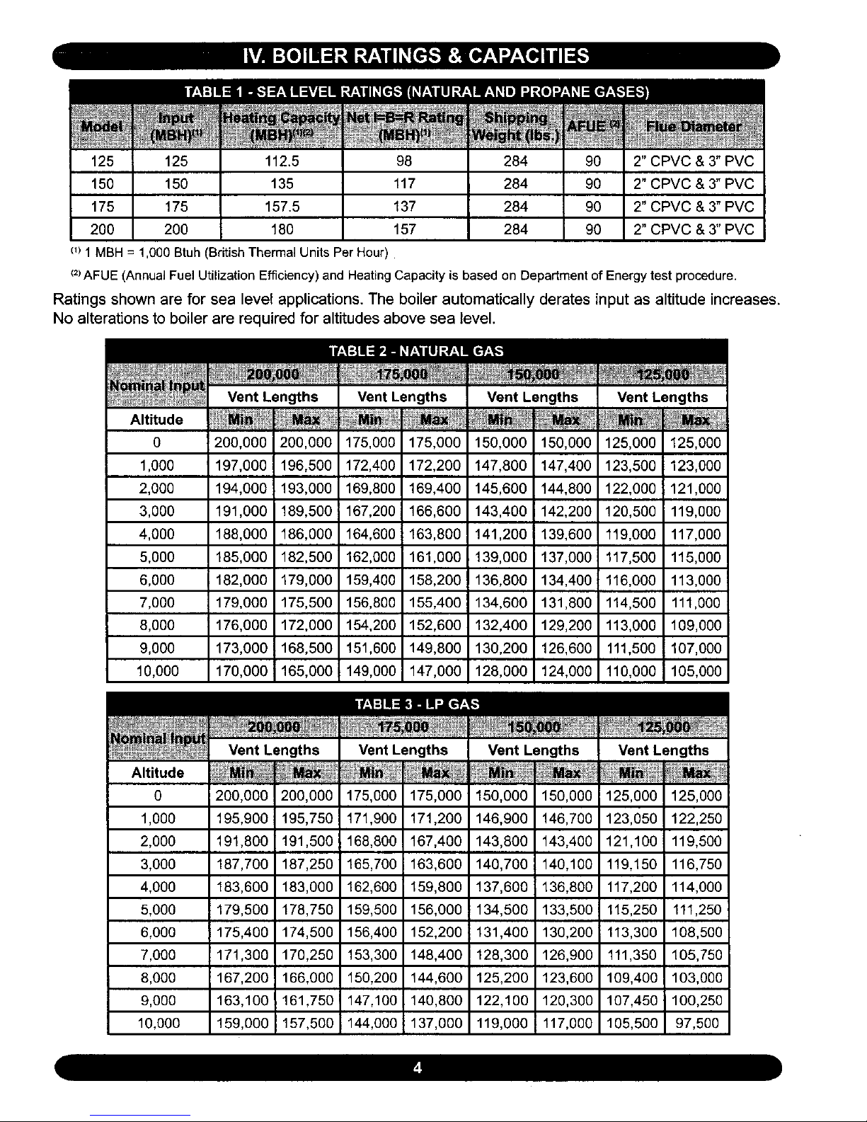
c_)1MBH = 1,000 Btuh(British ThermalUnits PerHour)
M
284 90
284 90
284 90
284 90
2" CPVC & 3" PVC
2" CPVC & 3" PVC
2" CPVC & 3" PVC
2" CPVC & 3" PVC
(2)AFUE (AnnualFuel Utilization Efficiency) and Heating Capacity is based on Department of Energytest procedure.
Ratings shown are for sea level applications. The boiler automatically derates input as altitude increases.
No alterations to boiler are required for altitudes above sea level.
Altitude
0
1,000
2,000
3,000
4,000
5,000
6,000
7,000
8,000
9,000
10,000
Vent Lengths
200,000 200,000
197,000 196,500
194,000 193,000
191,000 189,500
188,000 186,000
185,000 182,500
182,000 179,000
179,000 175,500
176,000 172,000
173,000 168,500
170,0001 165,000
Vent Lengths
175,000 175,000
172,400 172,200
169,800 169,400
167,200 i 166,600
164,6001 163,800
162,000 161,000
159,400 158,200
156,800 155,40C
154,200 152,600
151,600 149,800
149,000 147,000
Vent Lengths
150,000 150,000
147,800 147,400
145,600 144,800
143,400 142,200
141,2001 139,600
139,000 137,000
136,800 134,400
134,600 131,800
132,400 129,200
130,200 126,600
128,000 124,000
Vent
125,000
123,500
122,000
120,500
119,000
117,500
114,500
113,000
111,500
110,000
125,000
123,000
121,000
119,000
117,000
115,000
113,000
111,000
109,000
107,000
105,000
Altitude
0
1,000
2,000
3,000
4,000
5,000
6,000
7,000
8,000
9,000
10,000
200,000
195,900
191,800
187,700
183,600
179,500
175,400
171,300
167,200
163,100
159,000
200,000
195,750
191,500
187,250
183,000
178,750
174,500
170,250
166,000
161,750i
157,500
175,000
171,900
168,800
165,700
162,600
159,500
156,400
153,300
150,200
147,100
144,000
175,000
171,200
167,400
163,600
159,800
156,000
152,200
148,400
144,600
140,800
137,000
150,000
146,900
143,800
140,700
137,600
134,500
131,400
128,300
125,200
122,100
119,000
150,000
146,700
143,400
140,100
136,800
133,500
130,200
126,900
123,600
120,300
117,000
125,000
123,050
121,100
119,150
117,200
115,250
113,300
111,350
109,400
107,450
105,500
125,000
122,250
119,500
116,750
114,000
111,250
108,500
105,750
103,000
100,250
97,500
These low pressure gas-fired hot water boilers are design certified by CSA International, for use with
natural and propane gases. The boilers are constructed and hydrostatically tested for a maximum work-
ing pressure of 50 psig (pounds per square inch gauge) in accordance with A.S.M.E. (American Society
of Mechanical Engineers) Boiler and Pressure Vessel Code, Section IV Standards for heating boilers.
The Boilers are certified in accordance with ANSI (American National Standards Institute) Z21.13
standards as gas-fired, direct vent, condensing, hot water boilers.
The Heating Capacity indicates the amount of heat available after subtracting the losses up the stack.
Most of this heat is available to heat water. A small portion is heat loss from the jacket and surfaces of
the boiler, and it is assumed that this heat stays in the structure. The Net I=B=R Rating represents the
portion of the remaining heat that can be applied to heat the radiation or terminal units (i.e. finned tube
baseboard, cast iron radiators, radiant floor, etc.). The difference between the Heating Capacity and the
Net I=B=R Rating, called the piping and pickup allowance, establishes a reserve for heating the volume
of water in the system and offsetting heat losses from the piping. The Net I=B=R Ratings shown are
based on a piping and pickup factor of 1.15 in accordance with the I=B=R Standard as published by the
Hydronics Institute. The Net t=B=R Rating of the boiler selected should be greater than or equal to the
calculated peak heating load (heat toss) for the building or area(s) served by the boiler and associated hot
water heating systems. The manufacturer should be consulted before selecting a boiler for installations
having unusual piping and pickup requirements.
Complete all of _e following prior to installing the boiler.
This boiler product is a gas-fired, direct vent, con-
densing boiler and must be installed in accordance
with all applicable federal, state and local building
codes including, but not limited to the following:
United States - Installation shall conform
with National Fuel Gas Code (NFPA-54/ANSI
Z223.1 - latest revision)
Canada - Installation shall be in accordance
with CSA-B149.1 and .2 installation codes.
• Check to be sure you have selected the boiler
with the proper capacity before continuing the in-
stallation. The I=B=R Rating of the boiler selected
should be greater than or equal to the calculated
peak heating load (heat loss) for the building or
area(s) served by the boiler and associated hot
water heating systems. See Section IV, "Boiler
Ratings and Capacities, "for more information.
• Heat loss calculations should be based on
approved industry methods.
Where required by the authority having jurisdiction,
the installation must conform to the American Soci-
ety of Mechanical Engineers Safety Code for Con-
trols and Safety Devices for Automatically Fired
Boilers, No.CSD-I.
The installation must conform to the requirements
of the authority having jurisdiction or, in the ab-
sence of such requirements, to the National Fuel
Gas Code, ANSI Z223.1 - latest revision.
Installers- Follow local regulations with re-
spect to installation of CO (Carbon Monox-
ide) Detectors. Follow maintenance recom-
mendations in this manual.
Before selecting a location for the boiler, the follow-
ing should be considered. Each boiler considered
for installation must be:
• Supplied with the correct type of gas (natural
gas or propane).
• Connected to a suitable combustion air intake pip-
ing system to supply the correct amounts of fresh
(outdoor) air for combus_on (max. leng_ 60').
• Connected to a suitable venting system to re-
move the hazardous products of gas combus-
tion (max. length 60').
• Connectedto a suitable hot water heating
system.
• Suppliedwitha suitableelectricalsupplyfor
allboilermotorsandcontrols.
• Connectedto a properlylocatedthermostat
oroperatingcontrol.(not includedwithboiler)
• Placedon level surface (mustNOT be in-
stalledon carpeting)
• Condensatedrainline must be pitched down
to floor drain or external condensate pump with
reservoir at ¼"per foot (wood frame or blocks
may be used to raise boiler).
1. Select a location which is level, central to the
piping systems served and as close to the vent
and air intake terminals as possible.
2. Accessibility clearances, if more stringent (i.e.
larger clearances) than required fire protection
clearances, must be used for the boiler installa-
tion. Accessibility clearances may be achieved
with the use of removable walls or partitions.
3. The boiler is approved for installation in clos-
ets and on combustible floors. This boiler shall
NOT be installed on carpeting.
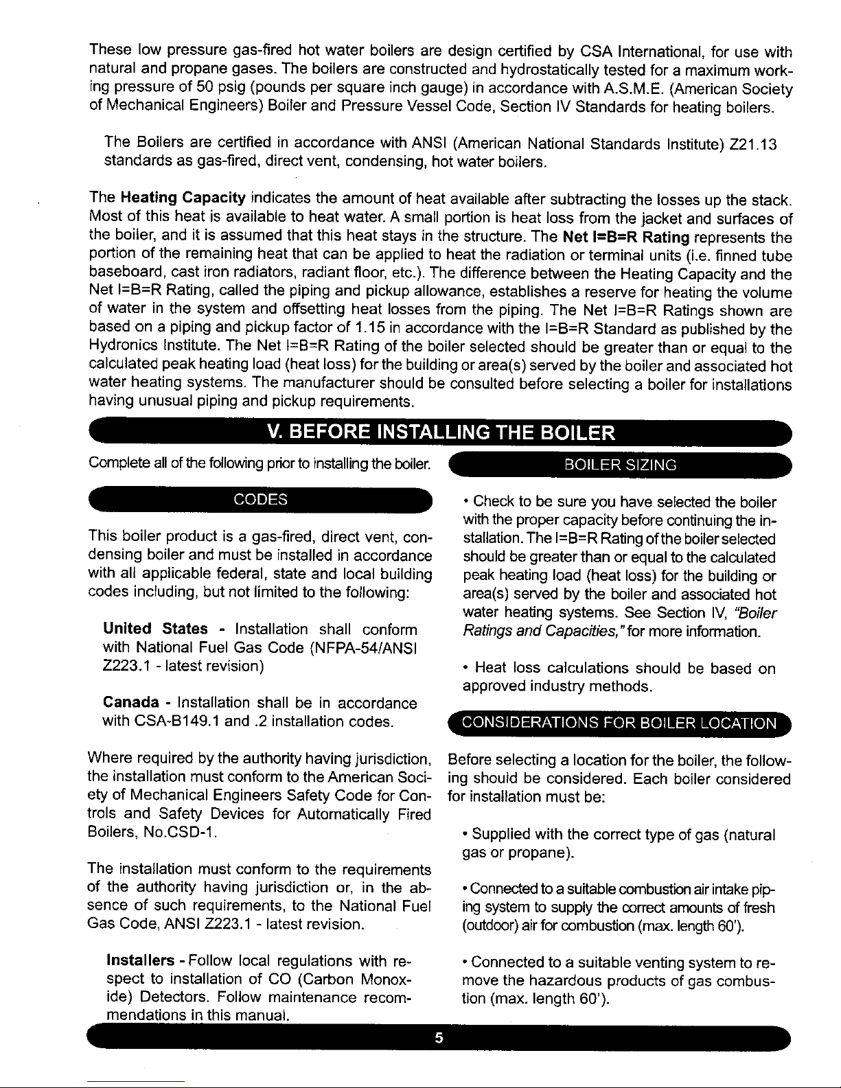
the front where passage is required for cleaning or
servicing, inspection or replacement of any parts
that normally may require such attention. Allow at
least 24" at the front and left side and 8" at the top
for servicing. No combustible clearances are re-
quired to venting or combustion air intake piping.
5. Equipment shall be installed in a location
which facilitates the operation of venting and
combustion air intake piping systems as de-
scribed in this manual.
6. Advise owner of boiler to keep venting and
combustion air intake passages free of obstruc-
tions. Both the venting and combustion air intake
piping systems connected to the outdoors must
permit flow through the piping systems without
restrictions for the boiler to operate.
7. The boiler shall be installed such that the
automatic gas ignition system components are
protected from water (dripping, spraying, rain,
etc.) during operation and service (circulator re-
placement, control replacement, etc.).
8. The boiler must be located where ambient
temperatures (minimum possible room temper-
atures where boiler is installed assuming boiler
is not in operation and therefore contributes no
heat to the space) are always at or above 32°F
to prevent freezing of liquid condensate.
Top 1" 8"
Left Side 8" 24"
Right Side 1"
Base 1"
Front 0" 24"
Back 1"
IntakeNent
0"
Piping
_lear Boiler Hot
1"
Water Piping
All distances measured from the cabinetof the boiler.
4. The clearances shown in Table 4 indicate re-
quired clearances per CSA listing. A min. 1" clear-
ance must be maintained between combustible
construction and each of the right, top and back
surfaces of the boiler. A min. 8" clearance is re-
quired on the left side, to allow room for the inlet
air pipe. An 18" clearance must be maintained at
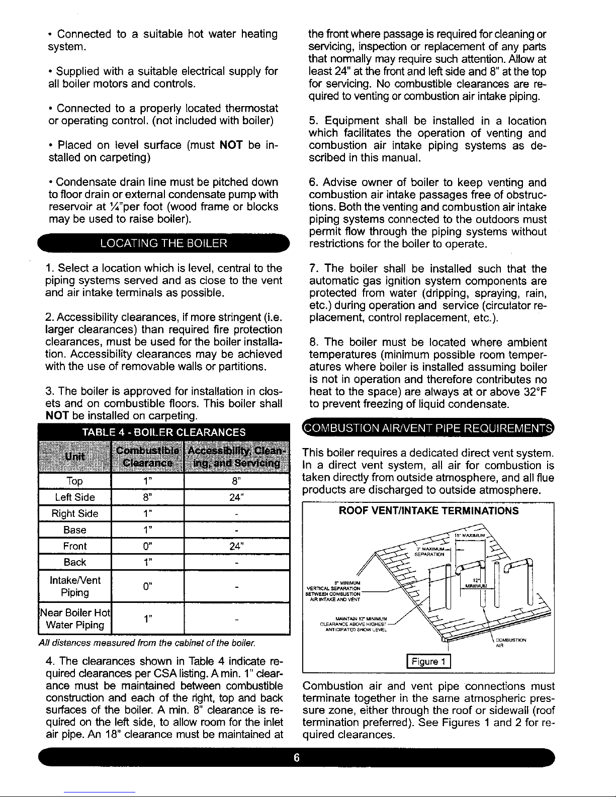
This boiler requires a dedicated direct vent system.
In a direct vent system, all air for combustion is
taken directly from outside atmosphere, and all flue
products are discharged to outside atmosphere.
ROOF VENT/INTAKE TERMINATIONS
i Figure 1 ]
Combustion air and vent pipe connections must
terminate together in the same atmospheric pres-
sure zone, either through the roof or sidewall (roof
termination preferred). See Figures 1 and 2 for re-
quired clearances.

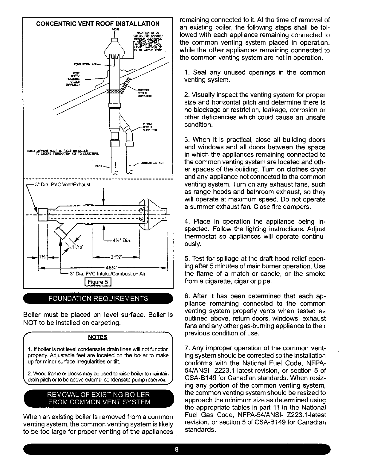
CONCENTRIC VENT ROOF INSTALLATION
, AIIOv_E_6NEST
3" Dia. PVC Vent/Exhaust !
-
! _1 46%" I,-
n 3" Dia. PVC Intake/Combustion Air
[ Figure 5 ]
remaining connected to it. At the time of removal of
an existing boiler, the following steps shall be fol-
lowed with each appliance remaining connected to
the common venting system placed in operation,
while the other appliances remaining connected to
the common venting system are not in operation.
1. Seal any unused openings in the common
venting system.
2. Visually inspect the venting system for proper
size and horizontal pitch and determine there is
no blockage or restriction, leakage, corrosion or
other deficiencies which could cause an unsafe
condition.
3. When it is practical, close all building doors
and windows and all doors between the space
in which the appliances remaining connected to
the common venting system are located and oth-
er spaces of the building. Turn on clothes dryer
and any appliance not connected to the common
venting system. Turn on any exhaust fans, such
as range hoods and bathroom exhaust, so they
will operate at maximum speed. Do not operate
a summer exhaust fan. Close fire dampers.
4. Place in operation the appliance being in-
spected. Follow the lighting instructions. Adjust
thermostat so appliances will operate continu-
ously.
5. Test for spillage at the draft hood relief open-
ing after 5 minutes of main burner operation. Use
the flame of a match or candle, or the smoke
from a cigarette, cigar or pipe.
Boiler must be placed on level surface. Boiler is
NOT to be installed on carpeting.
NOTES
1. Ifboiler is not level condensate drain lines will not function
properly, Adjustable feet are located on the boiler to make
up for minor surface irregularities or tilt,
2. Wood frame of blocks may be used to raise boiler to maintain
_drain pitch or to be above extemal condensate pump reservoir.J
When an existing boiler is removed from a common
venting system, the common venting system is likely
to be too large for proper venting of the appliances
6. After it has been determined that each ap-
pliance remaining connected to the common
venting system properly vents when tested as
outlined above, return doors, windows, exhaust
fans and any other gas-burning appliance to their
previous condition of use.
7. Any improper operation of the common vent-
ing system should be corrected so the installation
conforms with the National Fuel Code, NFPA-
54/ANSI -Z223.1-1atest revision, or section 5 of
CSA-B149 for Canadian standards. When resiz-
ing any portion of the common venting system,
the common venting system should be resized to
approach the minimum size as determined using
the appropriate tables in part 11 in the National
Fuel Gas Code, NFPA-54/ANSI- Z223.1-1atest
revision, or section 5 of CSA-B149 for Canadian
standards.

Theboiler should be placed to providethe most
directconnectionsto the combustionair,vent and
systempipingas possible.
Placecrated boiler as close to selectedlocation
aspossibleanduncrateboiler.Theuncratedboiler
maybemovedinto positionwithan appliancedol-
ly or 2-wheelhandtruck.The dolly or handtruck
shouldbe insertedunderthe right hand side of
theboiler.Itispossibletoslidethe boilerforashort
distanceonasmoothfloororsurface.
NuOTE: Refer to "Locating The Boiler" in Section V for re-_
ired clearances for servicing and maintenance. J
f
iA cAo.,-,o,AI
Copper supply and return piping must NOT be in-
stalled directly into aluminum boiler section castings
due to galvanic corrosion between dissimilar met-
als. Iron or steel bushings or pipe nipples should
be used between copper system piping and boiler
to make final connection to boiler. Also, the use of
dielectric unions is acceptable. The packaged boiler
is furnished with iron piping in the front boiler sec-
tion for the supply and return connections.
When the installation of the boiler is for a new heat-
ing system, first install all of the radiation units (pan-
els, radiators, baseboard, or tubing) and the supply
and return mains. After all heating system piping and
components have been installed, make final con-
nection of the system piping to the boiler.
Ahot water boiler installed above radiation level must
be equipped with a low water cut off device (included
with boiler). A periodic inspection is necessary, as is
flushing of float type devices, per low water cut off
manufacturers specific instructions.
DIAPHRAGM TYPE EXPANSION TANK PIPING
E_C_ T_f_ _VICE VAL_
--(_,_n[ VALOIS C_ FULL
PORT B_ VAL'_
_J TO_ATIC _R
V_. _/'_"X'/8"_F_t_i_O_J_'_i_°iN
.... ?ST _°_1_4 FC_ F_ WA_R
Figure 6 ]
Determine required system fill pressure, system de-
sign temperature, and system water content. Boiler
contains 2.6 gallons (U.S.). Size expansion tank ac-
cordingly. Consult expansion tank manufacturer for
proper sizing information. Connect properly sized
expansion tank (not furnished) as shown in Figure 6
for diaphragm type expansion tank. For diaphragm
type expansion tanks, adjust the tank air pressure
to match the system fill pressure. Install air vent
(fumished) as shown for diaphragm type expansion
tank system only. install make-up water connec-
tions as shown and per local codes. If a pressure
reducing valve is used, adjust to match the system
fill pressure. In connecting the cold make-up water
supply to the boiler, make sure that clean water sup-
ply is available. When the water supply is from a well
or pump, a sand strainer should be installed at the
pump.
RELIEF VALVE DISCHARGE PIPING
fPRESSUR[ REUEF0EVlC[
[FigureTI
The boiler is furnished with a relief valve and tem-
perature pressure gauge in the boiler parts bag. In-
stall vent retief valve as shown in Figure 7. Provide
¾" piping from the relief valve to a local floor drain,
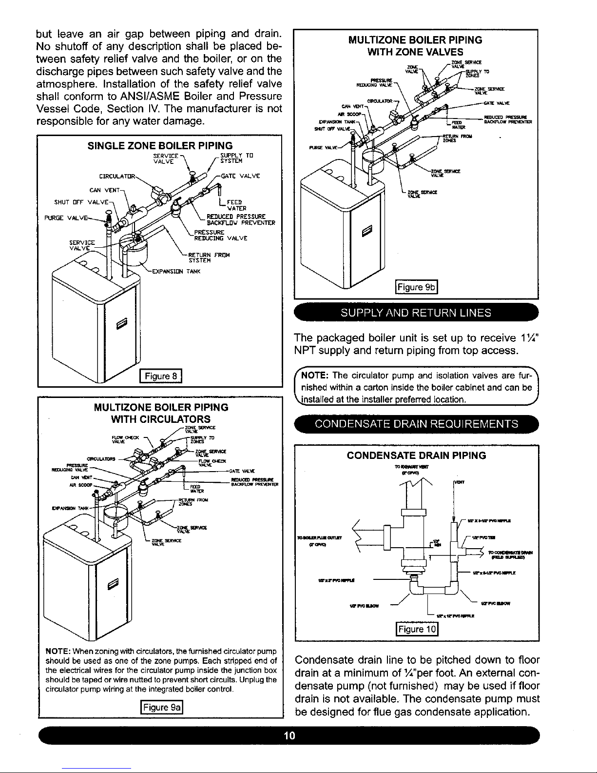
but leave an air gap betweenpiping and drain.
No shutoffof any descriptionshall be placed be-
tween safety reliefvalve and the boiler,or on the
dischargepipesbetweensuchsafetyvalveandthe
atmosphere.Installationof the safety reliefvalve
shall conformtoANSl/ASMEBoilerand Pressure
VesselCode, SectionIV.The manufactureris not
responsiblefor anywaterdamage.
SINGLE ZONE BOILER PIPING
SUPPLY TD
VALVE
VALVE
CAN VENT-
SHUT OFF LFEE_
VATER
PURGE RE_UCED PRESSURE
BACKFI.I]V PREVENTER
PRESSURE
SERVICE
RETURN FROH
SYSTEN
TANK
MULTIZONE BOILER PIPING
WITH CIRCULATORS
,GAE VAL_E
NOTE: When zoning with circulators, the furnished circulator pump
should be used as one of the zone pumps. Each stripped end of
the electrical wires for the circulator pump inside the junction box
should be taped or wire nutted to prevent short circuits. Unplug the
circulator pump wiring at the integrated boiler control.
MULTIZONE BOILER PIPING
WITH ZONE VALVES
The packaged boiler unit is set up to receive 11¼"
NPT supply and return piping from top access.
frNiOTE: The circulator and isolation valves fur-_
pump
are
shed within a carton inside the boiler cabinet and can beJ
/
_nstalled at the installer preferred location. J
CONDENSATE DRAIN PIPING
lo INWJI_ ,¢m't
Condensate drain line to be pitched down to floor
drain at a minimum of '/_"per foot. An external con-
densate pump (not furnished) may be used if floor
drain is not available. The condensate pump must
be designed for flue gas condensate application.

f
NOTES
1. Condensate trap is to be built in the field per Figure 10
2. Wood frame or blocks may be used to raise the boiler
to maintain drain pitch or to be above external condensate
pump reservoir.
3. There is a 115 volt AC receptacle provided on the service
switch junction box which.is located at the boiler right side, to
provide power for an external condensate pump (if needed).
,. j
The condensate trap is to be field installed as previ-
ously shown in Figure 10. Provided are ½" PVC fit-
tings for the condensate drain trap (assembled in the
field). The condensate drain is to be pitched down to
the floor drain at a minimum of 1¼,,per foot.
The ½" diameter schedule 40 PVC condensate
drain piping and pipe fittings must conform toANSI
standards and ASTM D1785 or D2846. Schedule
40 PVC cement and primer must conform to ASTM
D2564 or F493. In Canada, use CSA or ULC certi-
fied schedule 40 PVC drain pipe and cement.
A condensate pump with a reservoir (not furnished)
may be used to remove condensate to a drain line
(sanitary line) above boiler if a floor drain is not
available or is inaccessible.
ON INITIAL START UP THE CONDENSATE TRAP
MUST BE MANUALLY FILLED WITH WATER.
The following are the steps required to initially fill
the condensate trap for start up, these steps are
only required at the initial start up or if maintenance
requires draining of the condensate trap:
1. Pour about 1 cup of cold tap water into the
condensate trap vent.
2. Excess water should go through the conden-
sate drain line. Verify proper operation of the drain
line (and external condensate pump if used).
The boiler, when used in connection with a refrig-
eration system, must be installed so the chiller me-
dium is piped in parallel with the boiler with appro-
priate valves to prevent the chilled medium from
entering the boiler.
The boiler piping system of a hot water boiler con-
nected to heating coils located in air handling units
where they may be exposed to refrigerated air cir-
culation must be equipped with flow control valves
or other automatic means to prevent gravity circu-
lation of the boiler water during the cooling cycle.
/ibMPORTANT: To prevent damage to the gas_
urner and ensure proper operation of the unit, I
I installer must clean and remove all shavings from I
k_he interior of all PVC pipe used on the air intake.,,,/
For boilers connected to gas vents or chimneys, vent
installations shall be in accordance with part 7,Venting
of Equipment, of the National Fuel Gas Code, ANSI
Z223.1-1atest revision, CSA-B149.1 and B149.2, and
applicable provisions of the local building codes.
Provisions for combustion and ventilation air must
be in accordance with section 5.3, Air For Com-
bustion and Ventilation, of the National Fuel Gas
Code, ANSI Z223.1-1atest revision, CSA-B149.1
and B149.2, or applicable provisions of the local
building code.
outdoors through the combustion air intake pipe.
All flue products are discharged to the outdoors
through the vent pipe.
1. See Figures 1-2 in Section V, "Combustion Air
and Vent Pipe Requirements," for standard two-
pipe roof and sidewall terminations and Figures
3-5 (same section) for concentric vent termina-
tions (roof termination is preferred). Combus-
tion air and vent pipes must terminate together
in same atmospheric pressure zone as shown.
Construction through which vent and air intake
pipes may be installed is a minimum ¼" and max-
imum 24" thickness.
2. Combustion air and vent pipe fittings must con-
form to one of the following American National
Standards Institute (ANSI) and American Society
for Testing and Materials (ASTM) standards:
• D 1784 (schedule-40 CPVC)
These boilers require a dedicated direct vent sys-
tem. All air for combustion is taken directly from
• D1785 (schedule-40 PVC)

• D2665 (PVC-DWV)
• D2241 (SDR-21 and SDR-26 PVC)
• D2661 (ABS-DWV)
• F628 (schedule-40 ABS).
Pipe cement and primer must conform to ASTM
standards D2564 (PVC) or D2235 (ABS).
In Canada construct all combustion air and vent
pipes for this unit of CSA or ULC certified sched-
ule-40 CPVC, schedule-40 PVC, PVC-DWV or
ABS-DWV pipe and pipe cement. SDR pipe is
NOT approved in Canada.
3. Combustion air and vent piping connections
on boiler are 2", but must increase to 3". Due to
potential for flue gas temperatures over 155°1,
the first 5 feet of vent pipe must be CPVC (fur-
nished), the remaining vent pipe can be PVC.
If any elbows are employed within the first 2 ½'
feet of vent, they must be CPVC. Two 30" pieces
of 2" CPVC pipe and one 2" CPVC coupling are
furnished with the boiler. (Figure 11)
COMBUSTION AIR AND VENT PIPING
3 INCH INTAKE ANO
EXHAUST TERMINATqONS
2- By 3-TR ANS rllON tN
THE VERTICAL pOS ITION
EXHAUST TEE
(FURNISHEO}
2# (50.SMM) CPVC COUPLING
_-- (FURNISHED)
)_ 2" (50"BMM} CPVC vE NT PIPING
I __ (FUR NISHEO & REQUIR ED)
NOT IN
HORIZONAL
SECTION
Reduce the maximum vent length 5 feet per
each additional elbow.
4. Combustion air and vent piping to be pitched
back to boiler at minimum 1/,,,per foot from intake
and vent terminals so that all moisture in com-
bustion air and vent piping drains to boiler. Pipes
must be pitched continuously with no sags or low
spots where moisture can accumulate and block
the flow of air or flue gas. Combustion air and
vent pipes must be airtight and watertight.
5. Consideration for the following should be used
when determining an appropriate location for ter-
mination of combustion air and vent piping:
• Comply with all clearances required as
stated in paragraph 6 (below)
• Termination should be positioned where
vent vapors will not damage plants/shrubs,
air conditioning equipment, or siding on the
house.
• Termination should be positioned so that
it will not be effected by wind eddy, air born
leaves, snow, or recirculated flue gases.
• Termination should be positioned where it
will not be subjected to potential damage by
foreign objects, such as stones, balls, etc.
• Termination should be positioned where
vent vapors are not objectionable.
• Put vent on a wall away from the prevailing
winter wind. Locate or guard the vent to pre-
vent accidental contact with people or pets.
• Terminate the vent above normal snow-
line. Avoid locations where snow may drift
and block the vent. Ice or snow may cause
the boiler to shut down if the vent becomes
obstructed.
NOTE: The exhaust transition from 2" pipe to 3" pipe must_'_
e made in a vertical run. (Transition pieces not included.)_
6 ft. in length plus 60 ft. in length and up
four (4) 90° elbows to four (4) 90 ° elbows
The length of pipe is counted from the boiler jack-
et (air intake pipe) or from vent tee (vent pipe).
The first five feet of "Total Equivalent Length" of
vent pipe must be CPVC.
• Under certain conditions, flue gas will con-
dense, forming moisture, and may be corro-
sive. In such cases, steps should be taken
to prevent building materials at the vent from
being damaged by exhaust of flue gas.
6. The venting system shall terminate at least 3
feet above any forced air inlet (except the boiler's
combustion air inlet) within 10 feet. The venting
system shall terminate at least 12 inches from
any air opening into any building. The bottom
of the vent shall be located at least 12 inches
 Loading...