

Page 1
®
Electric Dryer
Use & Care Guide
Secadora eléctrica
Manual de uso y cuidado
Models/Modelos 110.8787✼, 8789✼
✼ = color number/número de color
W10114657 Sears Roebuck and Co., Hoffman Estates, IL 60179 U.S.A. www.sears.com
Page 2

TABLE OF CONTENTS
PROTECTION AGREEMENTS
PROTECTION AGREEMENTS.......................................................2
ARRANTY ........................................................................................3
DRYER SAFETY..............................................................................4
INSTALLATION INSTRUCTIONS ..................................................5
Tools and Parts ............................................................................5
Optional Pedestal.........................................................................5
Location Requirements ................................................................6
Electrical Requirements................................................................8
Electrical Connection ...................................................................9
Venting Requirements............................................................... 14
Plan Vent System ...................................................................... 15
Install Vent System.................................................................... 16
Install Leveling Legs .................................................................. 16
Connect Vent............................................................................. 17
Level Dryer................................................................................. 17
Reverse Door Swing.................................................................. 17
Complete Installation................................................................. 18
DRYER USE ................................................................................. 19
Starting Your Dryer.................................................................... 19
Stopping Your Dryer.................................................................. 20
Pausing or Restarting................................................................ 20
Control Locked.......................................................................... 20
Drying and Cycle Tips ............................................................... 20
Status Lights.............................................................................. 21
Cycles........................................................................................ 21
Options ...................................................................................... 22
Modifiers.................................................................................... 23
Changing Cycles, Options and Modifiers ................................. 23
End of Cycle Signal ................................................................... 24
TUMBLE FREE™ Heated Dryer Rack....................................... 24
DRYER CARE.............................................................................. 25
Cleaning the Dryer Location...................................................... 25
Cleaning the Lint Screen........................................................... 25
Cleaning the Dryer Interior ........................................................ 25
Removing Accumulated Lint..................................................... 25
Vacation and Moving Care........................................................ 25
Changing the Drum Light .......................................................... 26
TROUBLESHOOTING.................................................................. 26
SERVICE NUMBERS ............................................... BACK COVER
Master Protection Agreements
Congratulations on making a smart purchase. Your new
Kenmore® product is designed and manufactured for years of
dependable operation. But like all products, it may require
preventive maintenance or repair from time to time. That’s when
having a Master Protection Agreement can save you money and
aggravation.
Purchase a Master Protection Agreement now and protect
yourself from unexpected hassle and expense.
The Master Protection Agreement also helps extend the life of
your new product. Here’s what’s included in the Agreement:
✔ Expert service by our 12,000 professional repair specialists
✔ Unlimited service and no charge for parts and labor on all
covered repairs
✔ “No-lemon” guarantee – replacement of your covered
product if four or more product failures occur within twelve
months
✔ Product replacement if your covered product can’t be fixed
✔ Annual Preventive Maintenance Check at your request – no
extra charge
✔ Fast help by phone – phone support from a Sears technician
on products requiring in-home repair, plus convenient repair
scheduling
✔ Power surge protection against electrical damage due to
power fluctuations
✔ Rental reimbursement if repair of your covered product takes
longer than promised
Once you purchase the Agreement, a simple phone call is all that
it takes for you to schedule service. You can call anytime day or
night, or schedule a service appointment online.
Sears has over 12,000 professional repair specialists, who have
access to over 4.5 million quality parts and accessories. That’s
the kind of professionalism you can count on to help prolong the
life of your new purchase for years to come. Purchase your
Master Protection Agreement today!
Some limitations and exclusions apply. For prices and
additional information, call 1-800-827-6655.
Sears Installation Service
For Sears professional installation of home appliances, garage
door openers, water heaters, and other major home items, in the
U.S.A. call 1-800-4-MY-HOME
®
.
2
Page 3

KENMORE ELITE® APPLIANCE WARRANTY
ONE YEAR LIMITED WARRANTY
When installed, operated and maintained according to all
instructions supplied with the product, if this appliance fails due
to a defect in material or workmanship within one year from the
date of purchase, call 1-800-4-MY-HOME
repair.
TWO YEAR LIMITED WARRANTY ON SENSOR SMART™
ELECTRONIC BOARD
For two years from the date of purchase, when this dryer is
installed, operated and maintained according to all instructions
supplied with the product, Sears will replace the electronic
control board if defective in materials or workmanship. After the
first year, customer assumes any labor costs associated with
replacement of these parts.
If this appliance is used for other than private family purposes,
this warranty applies for only 90 days from the date of purchase.
THIS WARRANTY COVERS ONLY DEFECTS IN MATERIAL
AND WORKMANSHIP. SEARS WILL NOT PAY FOR:
1. Expendable items that can wear out from normal use,
including but not limited to filters, belts, light bulbs, and bags.
2. A service technician to instruct the user in correct product
installation, operation or maintenance.
3. A service technician to clean or maintain this product.
4. Damage to or failure of this product if it is not installed,
operated or maintained according to all instructions supplied
with the product.
5. Damage to or failure of this product resulting from accident,
abuse, misuse or use for other than its intended purpose.
6. Damage to or failure of this product caused by the use of
detergents, cleaners, chemicals or utensils other than those
recommended in all instructions supplied with the product.
7. Damage to or failure of parts or systems resulting from
unauthorized modifications made to this product.
®
to arrange for free
DISCLAIMER OF IMPLIED WARRANTIES; LIMITATION OF
REMEDIES
Customer’s sole and exclusive remedy under this limited
warranty shall be product repair as provided herein. Implied
warranties, including warranties of merchantability or fitness for a
particular purpose, are limited to one year or the shortest period
allowed by law. Sears shall not be liable for incidental or
consequential damages. Some states and provinces do not allow
the exclusion or limitation of incidental or consequential
damages, or limitations on the duration of implied warranties of
merchantability or fitness, so these exclusions or limitations may
not apply to you.
This warranty applies only while this appliance is used in the
United States and Canada.
This warranty gives you specific legal rights, and you may also
have other rights which vary from state to state.
Sears, Roebuck and Co.
Dept. 817WA, Hoffman Estates, IL 60179
Sears Canada Inc.
Toronto, Ontario, Canada M5B 2B8
PRODUCT RECORD
In the space below, record your complete model number, serial
number, and purchase date. You can find this information on the
model and serial number label located on the product.
Have this information available to help you obtain assistance or
service more quickly whenever you contact Sears concerning
your appliance.
Model number __ __ __. __________________________________________
Serial number___________________________________________________
Purchase date __________________________________________________
Save these instructions and your sales receipt for future
reference.
3
Page 4
DRYER SAFETY
Your safety and the safety of others are very important.
We have provided many important safety messages in this manual and on your appliance. Always read and obey all safety
messages.
This is the safety alert symbol.
This symbol alerts you to potential hazards that can kill or hurt you and others.
All safety messages will follow the safety alert symbol and either the word “DANGER” or “WARNING.”
These words mean:
You can be killed or seriously injured if you don't immediately
DANGER
WARNING
All safety messages will tell you what the potential hazard is, tell you how to reduce the chance of injury, and tell you what can
happen if the instructions are not followed.
IMPORTANT SAFETY INSTRUCTIONS
WARNING:
including the following:
■
Read all instructions before using the dryer.
■
Do not place items exposed to cooking oils in your dryer.
Items contaminated with cooking oils may contribute to
a chemical reaction that could cause a load to catch fire.
■
Do not dry articles that have been previously cleaned in,
washed in, soaked in, or spotted with gasoline, drycleaning solvents, or other flammable or explosive
substances as they give off vapors that could ignite or
explode.
■
Do not allow children to play on or in the dryer. Close
supervision of children is necessary when the dryer is
used near children.
■
Before the dryer is removed from service or discarded,
remove the door to the drying compartment.
■
Do not reach into the dryer if the drum is moving.
■
Do not install or store the dryer where it will be exposed
to the weather.
■
Do not tamper with controls.
To reduce the risk of fire, electric shock, or injury to persons when using the dryer, follow basic precautions,
follow instructions.
can be killed or seriously injured if you don't
You
instructions.
■
Do not repair or replace any part of the dryer or attempt
any servicing unless specifically recommended in this
Use and Care Guide or in published user-repair
instructions that you understand and have the skills to
carry out.
■
Do not use fabric softeners or products to eliminate static
unless recommended by the manufacturer of the fabric
softener or product.
■
Do not use heat to dry articles containing foam rubber or
similarly textured rubber-like materials.
■
Clean lint screen before or after each load.
■
Keep area around the exhaust opening and adjacent
surrounding areas free from the accumulation of lint, dust,
and dirt.
■
The interior of the dryer and exhaust vent should be
cleaned periodically by qualified service personnel.
■
See installation instructions for grounding requirements.
follow
SAVE THESE INSTRUCTIONS
4
Page 5
INSTALLATION INSTRUCTIONS
Tools and Parts
Gather the required tools and parts before starting installation.
Read and follow the instructions provided with any tools listed
here.
■ Flat-blade screwdriver
■ #2 Phillips screwdriver
■ Adjustable wrench that
opens to 1" (2.54 cm) or
hex-head socket wrench
(for adjusting dryer feet)
■ Wire stripper (for direct
wire installations)
■ Level
Parts supplied
Remove parts package from dryer drum. Check that all parts are
included.
4 Leveling legs
NOTE: Do not use leveling legs if installing the dryer on a
pedestal.
Parts needed
Check local codes. Check existing electrical supply and venting.
See “Electrical Requirements” and “Venting Requirements”
before purchasing parts.
■ For close-clearance installations between 31.5" (80.01 cm)
and 37" (93.98 cm), see “Plan Vent System” section for
venting requirements.
■ Vent clamps
■ Caulking gun and
compound (for installing
new exhaust vent)
■ Tin snips (new vent
installations)
■ ¼" nut driver or socket
wrench (recommended)
■ Tape measure
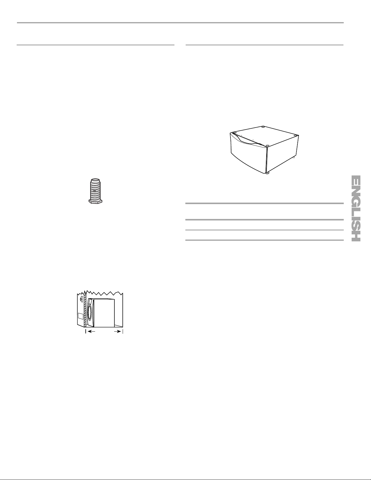
Optional Pedestal
Are you placing the dryer on a pedestal? You have the option of
purchasing pedestals of different heights separately for this dryer.
You may select a 10" (25.4 cm) pedestal or a 15.5" (39.4 cm)
pedestal with a storage drawer. The pedestal will add to the total
height of the dryer for a total height of approximately
46" (116.8 cm) or 51.5" (130.8 cm), respectively.
For a garage installation, you will need to place the 10" (25.4 cm)
pedestal at least 9" (22.9 cm) above the floor. You will need to
place the 15.5" (39.4 cm) pedestal at least 3" (7.6 cm) above the
floor.
Optional pedestal (15.5" [39.4 cm] model shown)
To order, call your local Sears store. For further information,
please call 1-800-4-MY-HOME
Pedestal
Height
10" (25.4 cm) White 46822
15.5" (39.4 cm) White 57822
®
(1-800-469-4663).
Color Part Number
37"
(93.98 cm)
Mobile home installations require metal exhaust system hardware
available for purchase from your local Sears store or Sears
Service Center. For further information, please call
1-800-4-MY-HOME
®
(1-800-469-4663).
5
Page 6
Location Requirements
WARNING
Explosion Hazard
Keep flammable materials and vapors, such as
gasoline, away from dryer.
Place dryer at least 18 inches (46 cm) above the floor
for a garage installation.
Failure to do so can result in death, explosion, or fire.
You will need
■ A location that allows for proper exhaust installation. See
“Venting Requirements.”
■ A separate 30-amp circuit.
■ If you are using a power supply cord, a grounded electrical
outlet located within 2 ft (61 cm) of either side of the dryer.
See “Electrical Requirements.”
■ A sturdy floor to support the total dryer weight of 200 lbs
(90.7 kg). The combined weight of a companion appliance
should also be considered.
■ A level floor with a maximum slope of 1" (2.5 cm) under entire
dryer. (If slope is greater than 1" [2.5 cm], install Extended
Dryer Feet Kit, Part Number 279810.) Clothes may not tumble
properly and automatic sensor cycles may not operate
correctly if dryer is not level.
■ For a garage installation, you will need to place the dryer at
least 18" (46 cm) above the floor. If you are using a pedestal,
you will need 18" (46 cm) to the bottom of the dryer.
Do not operate your dryer at temperatures below 45ºF (7ºC). At
lower temperatures, the dryer might not shut off at the end of an
automatic cycle. Drying times can be extended.
The dryer must not be installed or stored in an area where it will
be exposed to water and/or weather.
Check code requirements. Some codes limit, or do not permit,
installation of the dryer in garages, closets, mobile homes, or
sleeping quarters. Contact your local building inspector.
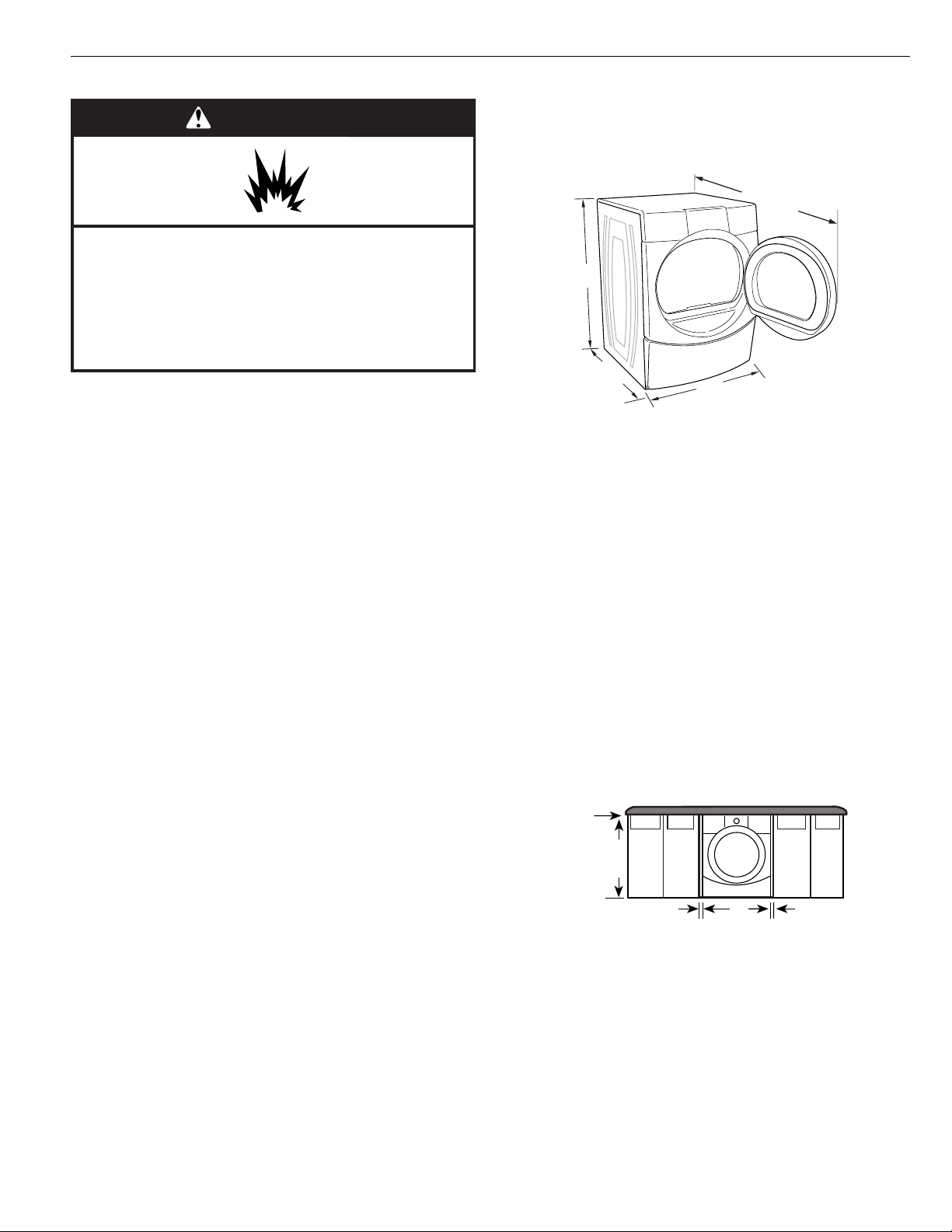
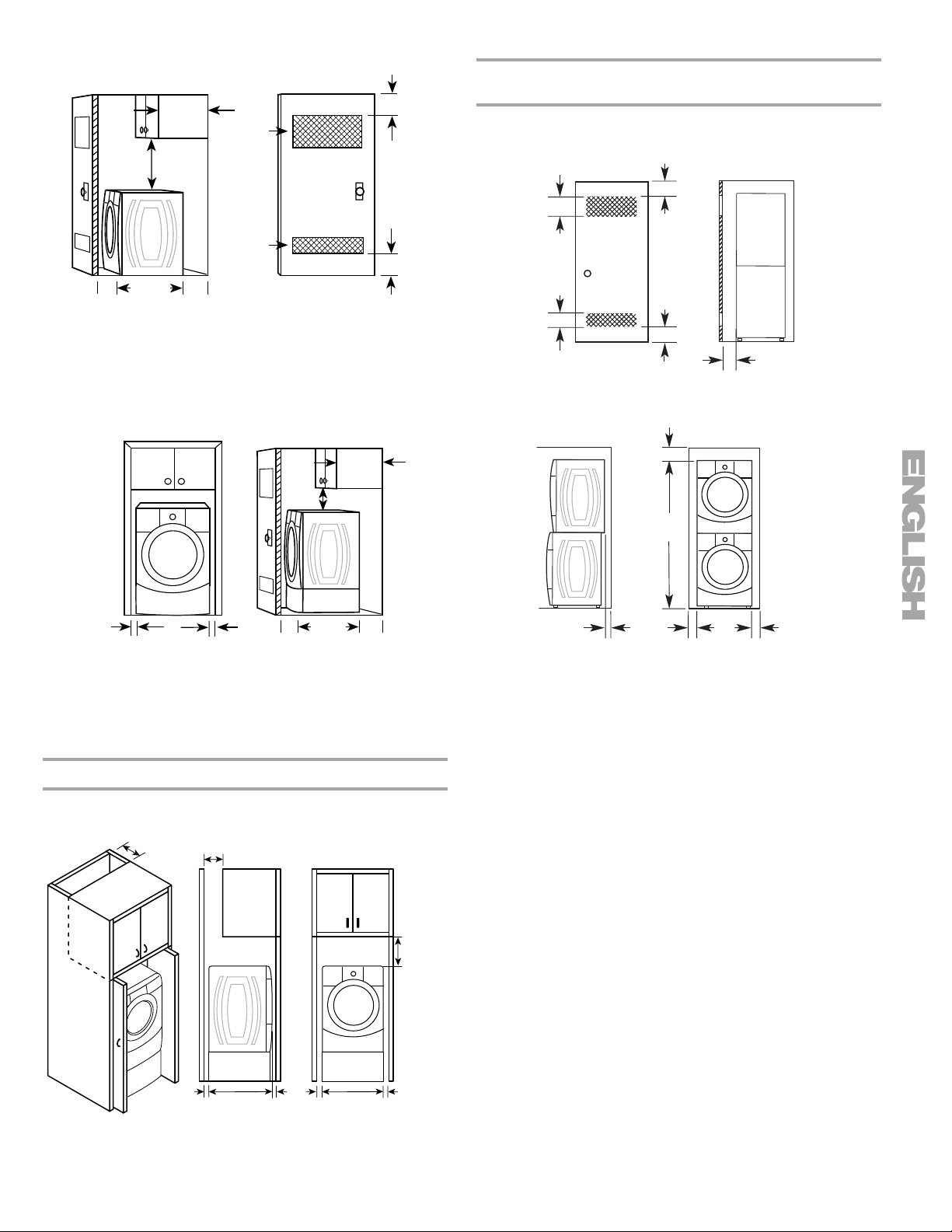
Installation clearances
The location must be large enough to allow the dryer door to
open fully.
Dryer Dimensions
50½"
(128.27 cm)
38"
(96.52 cm)
*31½"
(80.01 cm)
27"
(68.6 cm)
*Most installations require a minimum 5" (12.7 cm) clearance
behind the dryer for the exhaust vent with elbow. See “Venting
Requirements.”
Installation spacing for recessed area or closet installation
The following spacing dimensions are recommended for this
dryer. This dryer has been tested for spacing of 0" (0 cm)
clearance on the sides and rear. Recommended spacing should
be considered for the following reasons:
■ Additional spacing should be considered for ease of
installation and servicing.
■ Additional clearances might be required for wall, door and
floor moldings.
■ Additional spacing should be considered on all sides of the
dryer to reduce noise transfer.
■ For closet installation, with a door, minimum ventilation
openings in the top and bottom of the door are required.
Louvered doors with equivalent ventilation openings are
acceptable.
■ Companion appliance spacing should also be considered.
Custom undercounter installation - Dryer only
0"
(0 cm)
38" min.
(96.52 cm)
1"*
(2.5 cm)
27"
(68.6 cm)
1"*
(2.5 cm)
*Required spacing
6
Page 7
Closet installation - Dryer only
3"*
(7.6 cm)
3"*
(7.6 cm)
1"*
(2.5 cm)
18" min.*
(45.72 cm)
31½"
(80 cm)
A
14" max.*
(35.6 cm)
5"**
(12.7 cm)
48 in.
(310 cm2)
24 in.
(155 cm2)
2*
2*
B
A. Side view - closet or confined area
B. Closet door with vents
*Required spacing
**For side or bottom venting, 0" (0 cm) spacing is allowed.
Recessed or closet installation - Dryer on pedestal
14" max.*
(35.6 cm)
18" min.*
(45.72 cm)
Recommended installation spacing for recessed or
closet installation, with stacked washer and dryer
The dimensions shown are for the recommended spacing.
48 in.2 *
2
)
(310 cm
3"* (7.6 cm)
3"* (7.6 cm)
2
*
24 in.
(155 cm2)
*Required spacing
6"* (15.2 cm)
76"
(193 cm)
1"* (2.5 cm)
1"
(2.5 cm)
27"
(68.6 cm)
A
1"
(2.5 cm)
1"*
(2.5 cm)
31¹⁄₂"
(80 cm)
B
**
5"
(12.7 cm)
A. Recessed area
B. Side view - closet or confined area
*Required spacing
**For side or bottom venting, 0" (0 cm) spacing is allowed.
Installation spacing for cabinet installation
■ For cabinet installation, with a door, minimum ventilation
openings in the top of the cabinet are required.
7"* (17.8 cm)
7"* (17.8 cm)
9"*
(22.9 cm)
5"*
(12.7 cm)
1"
(2.5 cm)
27"
(68.6 cm)
1"
(2.5 cm)
*Required spacing
Mobile home - additional installation requirements
This dryer is suitable for mobile home installations.
The installation must conform to the Manufactured Home
Construction and Safety Standard, Title 24 CFR, Part 3280
(formerly the Federal Standard for Mobile Home Construction
and Safety, Title 24, HUD Part 280).
Mobile home installations require:
■ Metal exhaust system hardware, which is available for
purchase from your local Sears store or Sears Service Center.
■ Special provisions must be made in mobile homes to
introduce outside air into the dryer. The opening (such as a
nearby window) should be at least twice as large as the dryer
exhaust opening.
31¹⁄₂"
(80.0 cm)
1"*
(2.5 cm)
1"
(2.5 cm)
27"
(68.6 cm)
1"
(2.5 cm)
5"**
(12.7 cm)
*Required spacing
**For side or bottom venting, 0" (0 cm) spacing is allowed.
7
Page 8
Electrical Requirements
It is your responsibility
■ To contact a qualified electrical installer.
■ To be sure that the electrical connection is adequate and in
conformance with the National Electrical Code, ANSI/NFPA
70-latest edition and all local codes and ordinances.
The National Electric Code requires a 4-wire supply
connection for homes built after 1996, dryer circuits involved
in remodeling after 1996, and all mobile home installations.
A copy of the above code standards can be obtained from:
National Fire Protection Association, One Batterymarch Park,
Quincy, MA 02269.
■ To supply the required 3 or 4 wire, single phase, 120/240 volt,
60 Hz., AC only electrical supply (or 3 or 4 wire, 120/208 volt
electrical supply, if specified on the serial/rating plate) on a
separate 30-amp circuit, fused on both sides of the line. A
time-delay fuse or circuit breaker is recommended. Connect
to an individual branch circuit. Do not have a fuse in the
neutral or grounding circuit.
■ Do not use an extension cord.
■ If codes permit and a separate ground wire is used, it is
recommended that a qualified electrician determine that the
ground path is adequate.
Electrical Connection
To properly install your dryer, you must determine the type of
electrical connection you will be using and follow the instructions
provided for it here.
■ If local codes do not permit the connection of a neutral
ground wire to the neutral wire, see “Optional 3-wire
connection” section.
■ This dryer is manufactured ready to install with a 3-wire
electrical supply connection. The neutral ground wire is
permanently connected to the neutral conductor (white wire)
within the dryer. If the dryer is installed with a 4-wire electrical
supply connection, the neutral ground wire must be removed
from the external ground conductor screw (green screw), and
secured under the neutral terminal (center or white wire) of
the terminal block. When the neutral ground wire is secured
under the neutral terminal (center or white wire) of the
terminal block, the dryer cabinet is isolated from the neutral
conductor.
■ A 4-wire power supply connection must be used when the
appliance is installed in a location where grounding through
the neutral conductor is prohibited. Grounding through the
neutral is prohibited for (1) new branch-circuit installations,
(2) mobile homes, (3) recreational vehicles, and (4) areas
where local codes prohibit grounding through the neutral
conductors.
If using a power supply cord:
Use a UL listed power supply cord kit marked for use with
clothes dryers. The kit should contain:
■ A UL listed 30-amp power supply cord, rated
120/240 volt minimum. The cord should be type SRD or
SRDT and be at least 4 ft (1.22 m) long. The wires that
connect to the dryer must end in ring terminals or spade
terminals with upturned ends.
■ A UL listed strain relief.
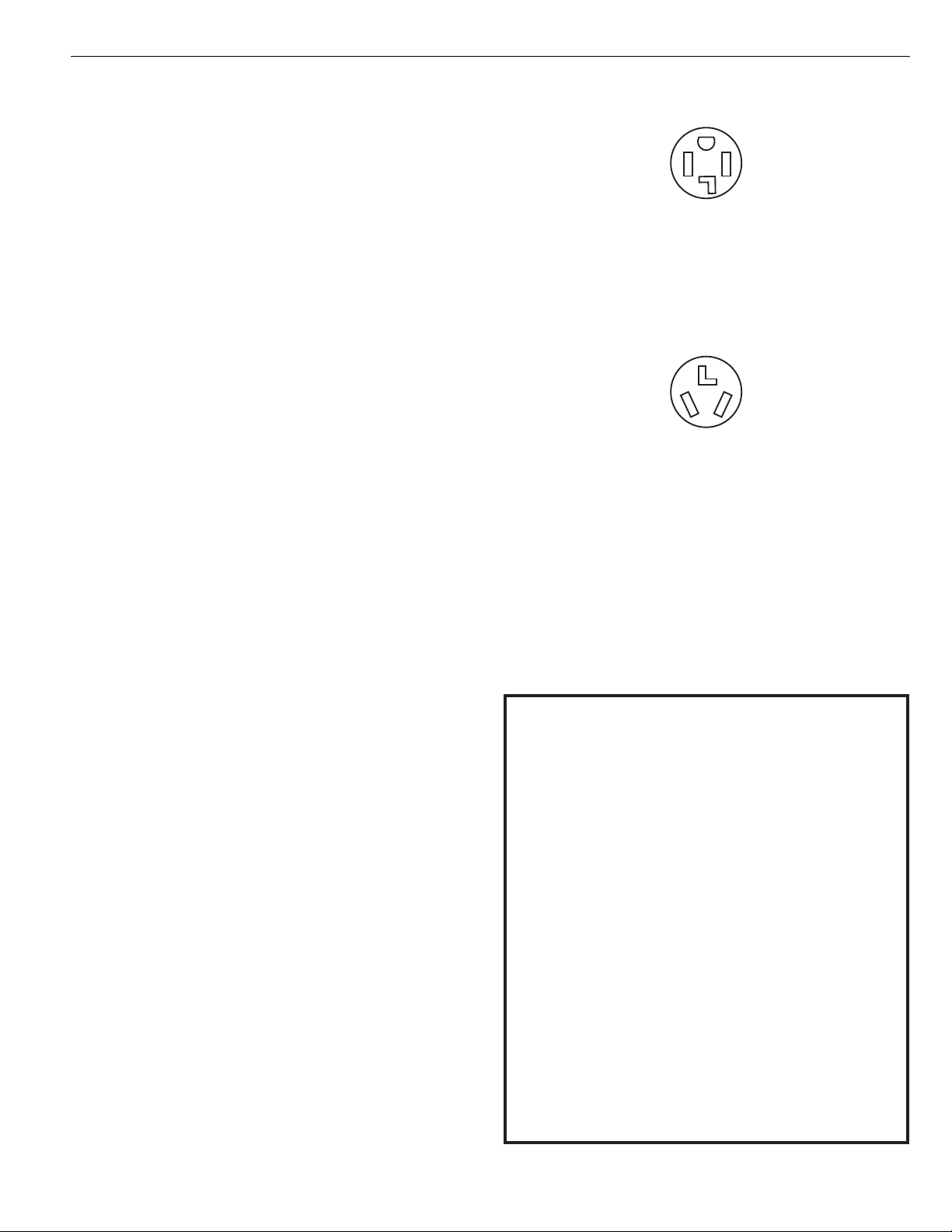
If your outlet looks like this:
4-wire receptacle (14-30R)
Then choose a 4-wire power supply cord with ring or spade
terminals and UL listed strain relief. The 4-wire power supply
cord, at least 4 ft (1.22 m) long, must have four 10-gauge copper
wires and match a 4-wire receptacle of NEMA Type 14-30R. The
ground wire (ground conductor) may be either green or bare. The
neutral conductor must be identified by a white cover.
If your outlet looks like this:
3-wire receptacle (10-30R)
Then choose a 3-wire power supply cord with ring or spade
terminals and UL listed strain relief. The 3-wire power supply
cord, at least 4 ft (1.22 m) long, must have three 10-gauge copper
wires and match a 3-wire receptacle of NEMA Type 10-30R.
If connecting by direct wire:
Power supply cable must match power supply (4-wire or 3-wire)
and be:
■ Flexible armored cable or nonmetallic sheathed copper cable
(with ground wire), protected with flexible metallic conduit. All
current-carrying wires must be insulated.
■ 10-gauge solid copper wire (do not use aluminum).
■ At least 5 ft (1.52 m) long.
GROUNDING INSTRUCTIONS
■
For a grounded, cord-connected dryer:
This dryer must be grounded. In the event of malfunction or
breakdown, grounding will reduce the risk of electric shock
by providing a path of least resistance for electric current.
This dryer uses a cord having an equipment-grounding
conductor and a grounding plug. The plug must be plugged
into an appropriate outlet that is properly installed and
grounded in accordance with all local codes and ordinances.
■
For a permanently connected dryer:
This dryer must be connected to a grounded metal,
permanent wiring system, or an equipment-grounding
conductor must be run with the circuit conductors and
connected to the equipment-grounding terminal or lead on
the dryer.
WARNING:
grounding conductor can result in a risk of electric shock.
Check with a qualified electrician or service representative
or personnel if you are in doubt as to whether the dryer is
properly grounded. Do not modify the plug on the power
supply cord: if it will not fit the outlet, have a proper outlet
installed by a qualified electrician.
Improper connection of the equipment-
SAVE THESE INSTRUCTIONS
8
Page 9
Electrical Connection
A
Power Supply Cord Direct Wire
WARNING
Fire Hazard
Use a new UL listed 30 amp power supply cord.
Use a UL listed strain relief.
Disconnect power before making electrical connections.
Connect neutral wire (white or center wire) to center
terminal (silver).
Ground wire (green or bare wire) must be connected to
green ground connector.
Connect remaining 2 supply wires to remaining
2 terminals (gold).
Securely tighten all electrical connections.
Failure to do so can result in death, fire, or
electrical shock.
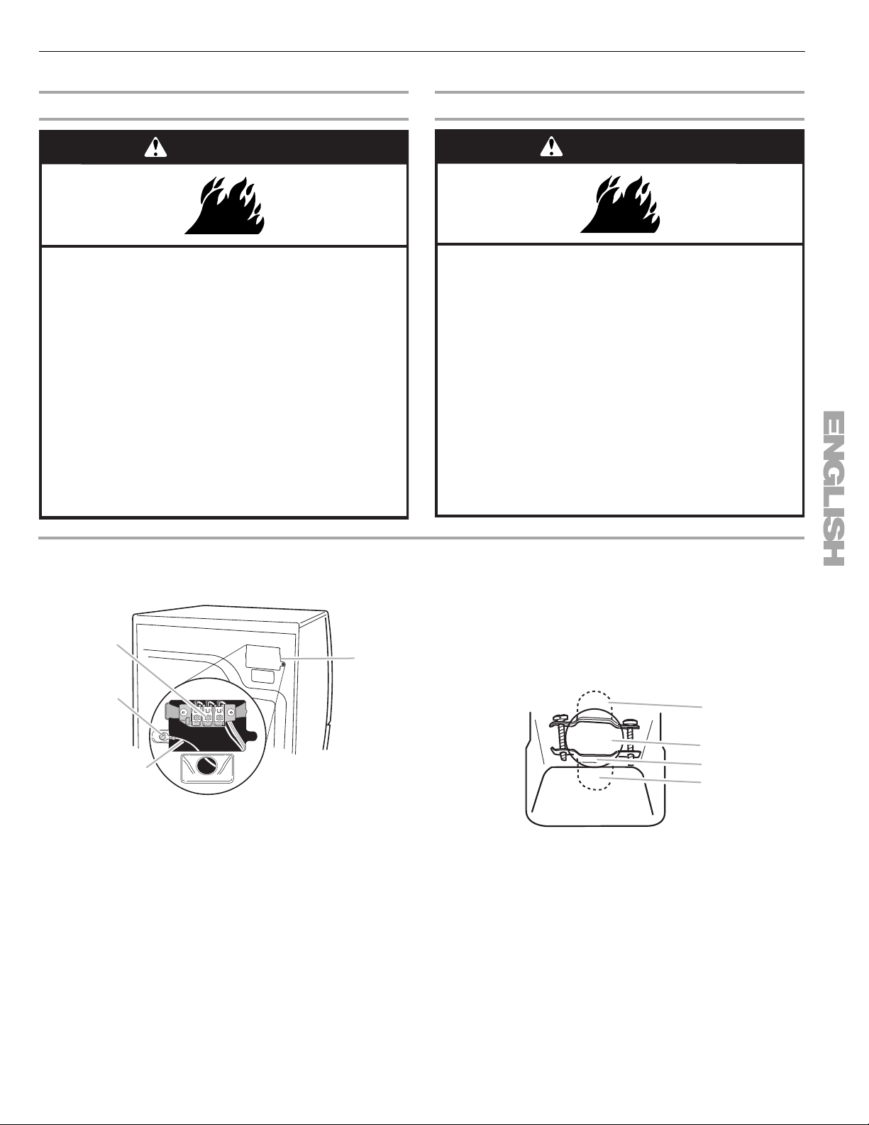
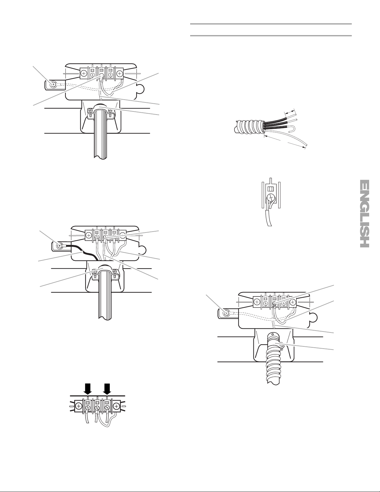
1. Disconnect power.
2. Remove the hold-down screw and terminal block cover.
C
D
B
WARNING
Fire Hazard
Use 10 gauge solid copper wire.
Use a UL listed strain relief.
Disconnect power before making electrical connections.
Connect neutral wire (white or center wire) to center
terminal (silver).
Ground wire (green or bare wire) must be connected to
green ground connector.
Connect remaining 2 supply wires to remaining
2 terminals (gold).
Securely tighten all electrical connections.
Failure to do so can result in death, fire, or
electrical shock.
3. Install strain relief.
Style 1: Power supply cord strain relief
■ Remove the screws from a ³⁄₄" (1.9 cm) UL listed strain
relief (UL marking on strain relief). Put the tabs of the two
clamp sections into the hole below the terminal block
opening so that one tab is pointing up and the other is
pointing down, and hold in place. Tighten strain relief
screws just enough to hold the two clamp sections
together.
A
A. Neutral ground wire
B. External ground conductor screw
C. Center, silver-colored terminal block screw
D. Terminal block cover and hold-down screw
B
C
D
A. Strain relief tab pointing up
B. Hole below terminal block opening
C. Clamp section
D. Strain relief tab pointing down
9
Page 10
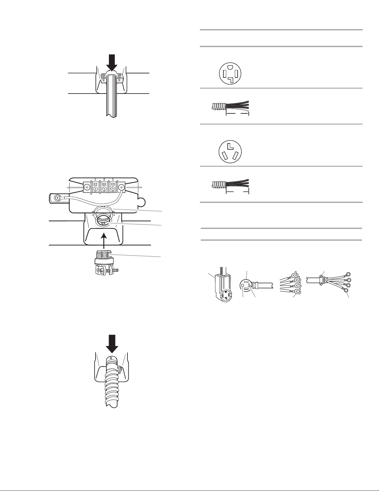
■ Put power supply cord through the strain relief. Be sure
A
G
that the wire insulation on the power supply cord is inside
the strain relief. The strain relief should have a tight fit with
the dryer cabinet and be in a horizontal position. Do not
further tighten strain relief screws at this point.
Electrical Connection Options
If your home has: And you will be
connecting to:
4-wire receptacle
(NEMA Type 14-30R)
A UL listed, 120/
240-volt
minimum,
30-amp, dryer
power supply
cord*
Go to Section
4-wire connection:
Power supply cord
Style 2: Direct wire strain relief
■ Unscrew the removable conduit connector and any
screws from a ³⁄₄" (1.9 cm) UL listed strain relief (UL
marking on strain relief). Put the threaded section of the
strain relief through the hole below the terminal block
opening. Reaching inside the terminal block opening,
screw the removable conduit connector onto the strain
relief threads.
B
C
A. Removable conduit connector
B. Hole below terminal block opening
C. Strain relief threads
■ Put direct wire cable through the strain relief. The strain
relief should have a tight fit with the dryer cabinet and be
in a horizontal position. Tighten strain relief screw against
the direct wire cable.
4-wire direct A fused
disconnect or
4-wire connection:
Direct Wire
circuit breaker
5"
(12.7 cm)
3-wire receptacle
(NEMA type 10-30R)
box*
A UL listed, 120/
240-volt
3-wire connection:
Power supply cord
minimum,
30-amp, dryer
power supply
cord*
3-wire direct A fused
disconnect or
3-wire connection:
Direct Wire
circuit breaker
3¹⁄₂"
(8.9 cm)
box*
*If local codes do not permit the connection of a cabinet-ground
conductor to the neutral wire, go to “Optional 3-wire
connection” section.
4-wire connection: Power supply cord
IMPORTANT: A 4-wire connection is required for mobile homes
and where local codes do not permit the use of 3-wire
connections.
A
BF
D
C
A. 4-wire receptacle (NEMA type 14-30R)
B. 4-prong plug
C. Ground prong
D. Neutral prong
E. Spade terminals with upturned ends
F. ¾" (1.9 cm) UL listed strain relief
G. Ring terminals
E
4. Now complete installation following instructions for your type
of electrical connection:
4-wire (recommended)
3-wire (if 4-wire is not available)
10
Page 11
1. Remove center silver-colored terminal block screw.
D
E
2. Remove neutral ground wire from external ground conductor
screw. Connect neutral ground wire and the neutral wire
(white or center wire) of power supply cord under center,
silver-colored terminal block screw. Tighten screw.
A
C
B
D
E
A. External ground conductor screw - Dotted line shows
position of NEUTRAL ground wire before being moved to
center silver-colored terminal block screw.
B. Center silver-colored terminal block screw
C. Neutral ground wire
D. Neutral wire (white or center wire)
E. ¾" (1.9 cm) UL listed strain relief
4-wire connection: Direct wire
IMPORTANT: A 4-wire connection is required for mobile homes
and where local codes do not permit the use of 3-wire
connections.
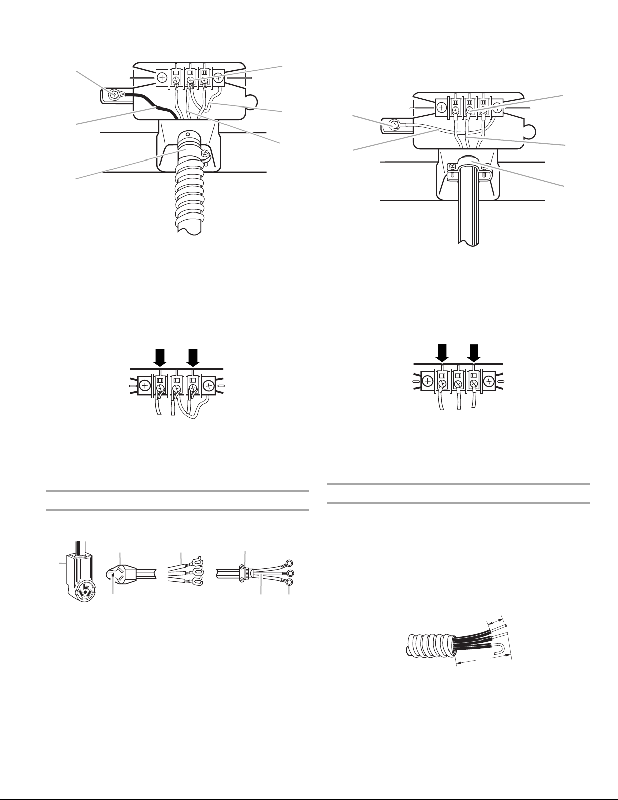
Direct wire cable must have 5 ft (1.52 m) of extra length so dryer
can be moved if needed.
Strip 5" (12.7 cm) of outer covering from end of cable, leaving
bare ground wire at 5" (12.7 cm). Cut 1¹⁄₂" (3.8 cm) from
3 remaining wires. Strip insulation back 1" (2.5 cm). Shape ends
of wires into a hook shape.
1"
(2.5 cm)
5"
(12.7 cm)
When connecting to the terminal block, place the hooked end of
the wire under the screw of the terminal block (hook facing right),
squeeze hooked end together and tighten screw, as shown.
3. Connect ground wire (green or bare) of power supply cord to
external ground conductor screw. Tighten screw.
A
B
F
C
A. External ground conductor screw
B. Ground wire (green or bare) of power supply cord
C.
³⁄₄
" (1.9 cm) UL listed strain relief
D. Center silver-colored terminal block screw
E. Neutral ground wire
F. Neutral wire (white or center wire)
4. Connect the other wires to outer terminal block screws.
Tighten screws.
1. Remove center silver-colored terminal block screw.
2. Remove neutral ground wire from external ground conductor
screw. Connect neutral ground wire and place the hooked
end (hook facing right) of the neutral wire (white or center
wire) of direct wire cable under the center screw of the
terminal block. Squeeze hooked ends together. Tighten
screw.
B
A
C
D
E
5. Tighten strain relief screws.
6. Insert tab of terminal block cover into slot of dryer rear panel.
Secure cover with hold-down screw.
7. You have completed your electrical connection. Now go to
“Venting Requirements.”
A. External ground conductor screw - Dotted line shows
position of NEUTRAL ground wire before being moved to
center silver-colored terminal block screw.
B. Center silver-colored terminal block screw
C. Neutral ground wire
D. Neutral wire (white or center wire)
E. ¾" (1.9 cm) UL listed strain relief
11
Page 12
3. Connect ground wire (green or bare) of direct wire cable to
D
E
F
external ground conductor screw. Tighten screw.
A
1. Loosen or remove center silver-colored terminal block screw.
2. Connect neutral wire (white or center wire) of power supply
cord to the center, silver-colored terminal screw of the
terminal block. Tighten screw.
C
B
C
A. External ground conductor screw
B. Ground wire (green or bare) of power supply cable
C. ¾" (1.9 cm) UL listed strain relief
D. Center silver-colored terminal block screw
E. Neutral ground wire
F. Neutral wire (white or center wire)
4. Place the hooked ends of the other direct wire cable wires
under the outer terminal block screws (hooks facing right).
Squeeze hooked ends together. Tighten screws.
A
B
A. External ground conductor screw
B. Neutral ground wire
C. Center silver-colored terminal block screw
D. Neutral wire (white or center wire)
³⁄₄
" (1.9 cm) UL listed strain relief
E.
3. Connect the other wires to outer terminal block screws.
Tighten screws.
D
E
5. Tighten strain relief screw.
6. Insert tab of terminal block cover into slot of dryer rear panel.
Secure cover with hold-down screw.
7. You have completed your electrical connection. Now go to
“Venting Requirements.”
3-wire connection: Power supply cord
Use where local codes permit connecting cabinet-ground
conductor to neutral wire.
B
D
A
C
A. 3-wire receptacle (NEMA type 10-30R)
B. 3-wire plug
C. Neutral prong
D. Spade terminals with up turned ends
³⁄₄
" (1.9 cm) UL listed strain relief
E.
F. R i ng t er mi n al s
G. Neutral (white or center wire)
E
F
G
4. Tighten strain relief screws.
5. Insert tab of terminal block cover into slot of dryer rear panel.
Secure cover with hold-down screw.
6. You have completed your electrical connection. Now go to
“Venting Requirements.”
3-wire connection: Direct wire
Use where local codes permit connecting cabinet-ground
conductor to neutral wire.
Direct wire cable must have 5 ft (1.52 m) of extra length so dryer
can be moved if needed.
Strip 3¹⁄₂" (8.9 cm) of outer covering from end of cable. Strip
insulation back 1" (2.5 cm). If using 3-wire cable with ground
wire, cut bare wire even with outer covering. Shape ends of wires
into a hook shape.
1"
(2.5 cm)
3¹⁄₂"
(8.9 cm)
12
Page 13
When connecting to the terminal block, place the hooked end of
C
D
the wire under the screw of the terminal block (hook facing right),
squeeze hooked end together and tighten screw, as shown.
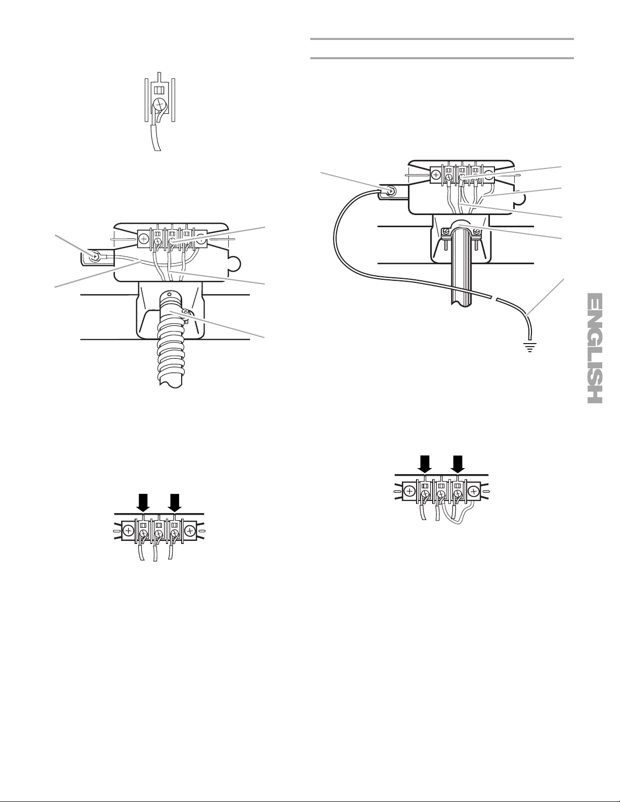
Optional 3-wire connection
Use for direct wire or power supply cord where local codes
do not permit connecting cabinet-ground conductor to
neutral wire.
1. Remove center silver-colored terminal block screw.
2. Remove neutral ground wire from external ground conductor
screw. Connect neutral ground wire and the neutral wire
(white or center wire) of power supply cord/cable under
center, silver-colored terminal block screw. Tighten screw.
1. Loosen or remove center silver-colored terminal block screw.
2. Place the hooked end of the neutral wire (white or center wire)
of direct wire cable under the center screw of terminal block
(hook facing right). Squeeze hooked end together. Tighten
screw.
A
B
D
E
A. External ground conductor screw
B. Neutral ground wire
C. Center silver-colored terminal block screw
D. Neutral wire (white or center wire)
E.
³⁄₄
" (1.9 cm) UL listed strain relief
3. Place the hooked ends of the other direct wire cable wires
under the outer terminal block screws (hooks facing right).
Squeeze hooked ends together. Tighten screws.
A
A. External ground conductor screw
B. Center silver-colored terminal block screw
C. Neutral ground wire
D. Neutral wire (white or center wire)
E.
³⁄₄
" (1.9 cm) UL listed strain relief
F. Grounding path determined by a qualified electrician
3. Connect the other wires to outer terminal block screws.
Tighten screws.
B
C
E
F
4. Tighten strain relief screw.
5. Insert tab of terminal block cover into slot of dryer rear panel.
Secure cover with hold-down screw.
6. You have completed your electrical connection. Now go to
“Venting Requirements.”
4. Tighten strain relief screws.
5. Connect a separate copper ground wire from the external
ground conductor screw to an adequate ground.
6. Insert tab of terminal block cover into slot of dryer rear panel.
Secure cover with hold-down screw.
13
Page 14
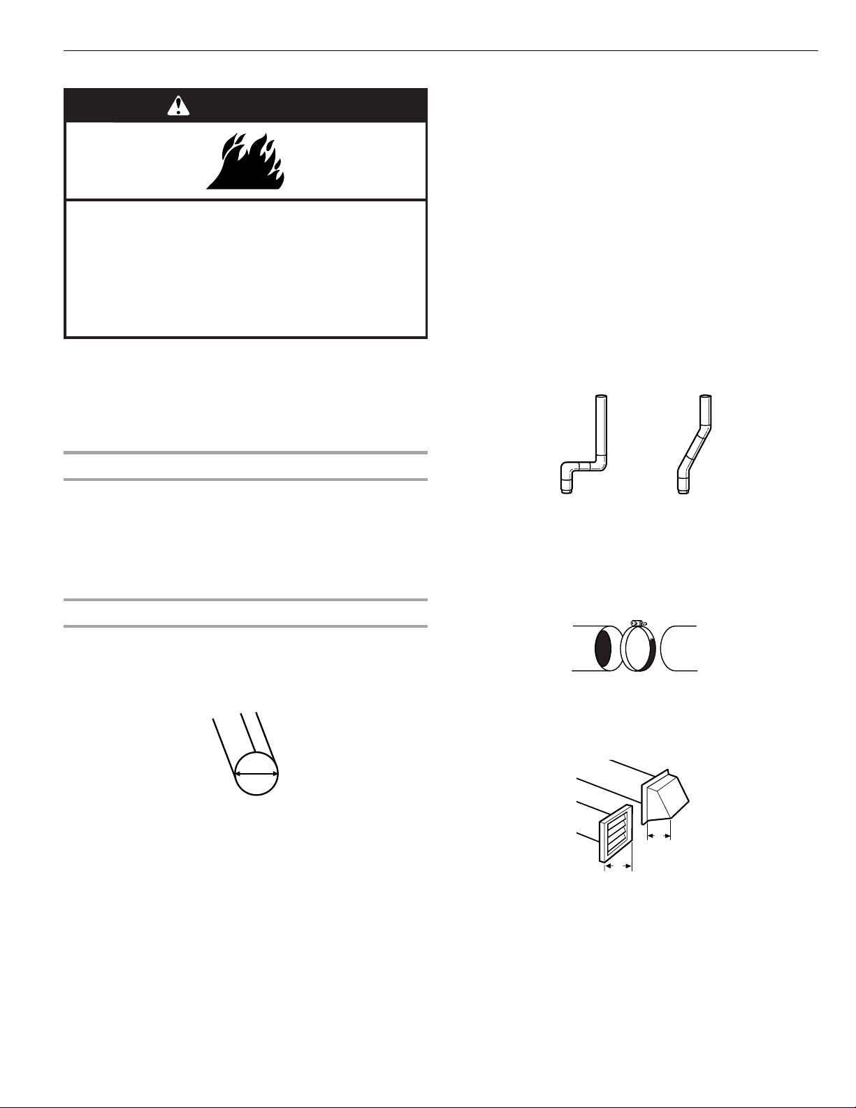
Venting Requirements
WARNING
Fire Hazard
Use a heavy metal vent.
Do not use a plastic vent.
Do not use a metal foil vent.
Failure to follow these instructions can result in death
or fire.
WARNING: To reduce the risk of fire, this dryer MUST BE
EXHAUSTED OUTDOORS.
IMPORTANT: Observe all governing codes and ordinances.
The dryer exhaust must not be connected into any gas vent,
chimney, wall, ceiling or a concealed space of a building.
If using an existing vent system
Rigid metal vent
■ For best drying performance, rigid metal vents are
recommended.
■ Rigid metal vent is recommended to avoid crushing and
kinking.
Flexible metal vent
■ Flexible metal vents are acceptable only if accessible for
cleaning.
■ Flexible metal vent must be fully extended and supported
when the dryer is in its final location.
■ Remove excess flexible metal vent to avoid sagging and
kinking that may result in reduced airflow and poor
performance.
■ Do not install flexible metal vent in enclosed walls, ceilings or
floors.
Elbows
45° elbows provide better airflow than 90° elbows.
■ Clean lint from the entire length of the system and make sure
exhaust hood is not plugged with lint.
■ Replace any plastic or metal foil vent with rigid or flexible
heavy metal vent.
■ Review Vent system chart. Modify existing vent system if
necessary to achieve the best drying performance.
If this is a new vent system
Vent material
■ Use a heavy metal vent. Do not use plastic or metal foil vent.
■ 4" (10.2 cm) heavy metal exhaust vent and clamps must be
used. DURASAFE™ venting products are recommended.
4"
10.2 cm
4" (10.2 cm) heavy metal exhaust vent
DURASAFE™ vent products can be purchased from your
dealer. For further information, please call
1-800-4-MY-HOME
www.sears.com.
®
(1-800-469-4663) or visit our website at
Good Better
Clamps
■ Use clamps to seal all joints.
■ Exhaust vent must not be connected or secured with screws
or other fastening devices that extend into the interior of the
duct. Do not use duct tape.
Clamp
Exhaust
Recommended hood styles are shown here.
B
A
4"
(10.2 cm)
4"
(10.2 cm)
A. Louvered hood style
B. Box hood style
14
Page 15
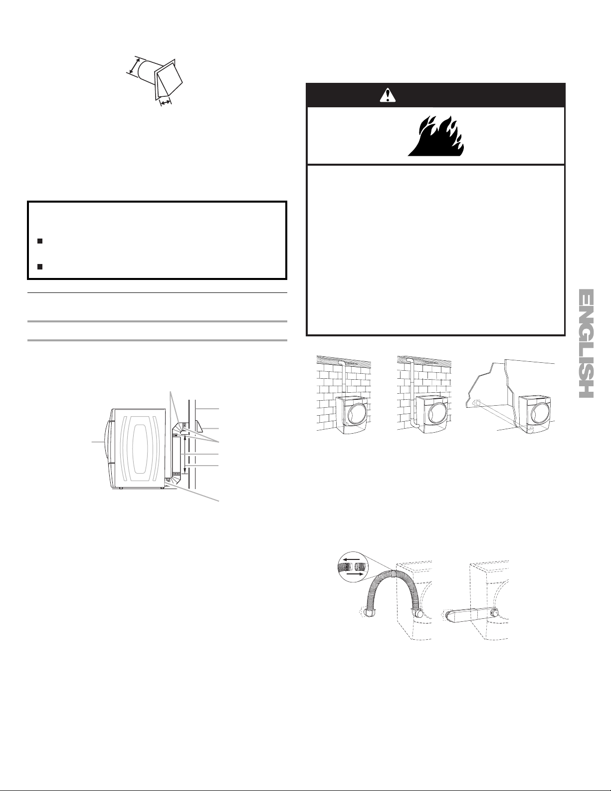
The angled hood style (shown here) is acceptable.
4"
(10.2 cm)
Optional exhaust installations
This dryer can be converted to exhaust out the right side, left
side, or through the bottom.
dryer converted.
Contact your local dealer to have the
2½"
(6.4 cm)
■ An exhaust hood should cap the vent to keep rodents and
insects from entering the home.
■ Exhaust hood must be at least 12" (30.5 cm) from the ground
or any object that may be in the path of the exhaust (such as
flowers, rocks or bushes, snow line, etc.).
■ Do not use an exhaust hood with a magnetic latch.
Improper venting can cause moisture and lint to collect
indoors, which may result in:
Moisture damage to woodwork, furniture, paint, wallpaper,
carpets, etc.
Housecleaning problems and health problems.
Plan Vent System
Choose your exhaust installation type
Recommended exhaust installations
Typical installations vent the dryer from the rear of the dryer.
Other installations are possible.
B
WARNING
Fire Hazard
Cover unused exhaust holes with one of the
following kits:
279818 (white)
279915 (black diamond)
280102 (pacific blue)
280103 (champagne)
280189 (barolo)
Contact your local dealer.
Failure to follow these instructions can result in death,
fire, electrical shock, or serious injury.
A
A. Dryer
B. Elbow
C. Wall
D. Exhaust hood
C
D
E
F
G
H
E. Clamps
F. Rigid metal or flexible metal vent
G. Vent length necessary to connect elbows
H. Exhaust outlet
A
A. Standard rear offset exhaust installation
B. Left or right side exhaust installation
C. Bottom exhaust installation (not an option
with pedestal installations)
B
C
Alternate installations for close clearances
Venting systems come in many varieties. Select the type best for
your installation. Two close-clearance installations are shown.
Refer to the manufacturer’s instructions.
AB
A. Over-the-top installation (also available with one offset elbow)
B. Periscope installation
NOTE: The following kits for close clearance alternate
installations are available for purchase. For further information,
please call 1-800-4-MY-HOME
®
(1-800-469-4663).
15
Page 16
■ Over-the-Top Installation:
Part Number 26-49900
■ Periscope Installation (For use with dryer vent to wall vent
mismatch):
Part Number 26-49901 - Less than 5" (12.7 cm) mismatch
Part Number 26-49908 - 5" (12.7 cm) to 18" (45.72 cm)
mismatch
Part Number 26-49904 - 18" (45.72 cm) to 29" (73.66 cm)
mismatch
Part Number 26-49905 - 29" (73.66 cm) to 50" (127 cm)
mismatch
Special provisions for mobile home installations
The exhaust vent must be securely fastened to a noncombustible
portion of the mobile home structure and must not terminate
beneath the mobile home. Terminate the exhaust vent outside.
Determine vent path
Vent system chart
NOTE: Side and bottom exhaust installations have a 90º turn
inside the dryer. To determine maximum exhaust length, add one
90º turn to the chart.
Number of
90º turns
or elbows
0Rigid metal
1Rigid metal
2Rigid metal
3Rigid metal
4Rigid metal
Type of
vent
Flexible metal
Flexible metal
Flexible metal
Flexible metal
Flexible metal
Box or
Louvered
hoods
64 ft (20 m)
36 ft (11 m)
54 ft (16.5 m)
31 ft (9.4 m)
44 ft (13.4 m)
27 ft (8.2 m)
35 ft (10.7 m)
25 ft (7.6 m)
27 ft (8.2 m)
23 ft (7 m)
Angled
hoods
58 ft (17.7 m)
28 ft (8.5 m)
48 ft (14.6 m)
23 ft (7 m)
38 ft (11.6 m)
19 ft (5.8 m)
29 ft (8.8 m)
17 ft (5.2 m)
21 ft (6.4 m)
15 ft (4.6 m)
Install Vent System
1. Install exhaust hood. Use caulking compound to seal exterior
wall opening around exhaust hood.
2. Connect vent to exhaust hood. Vent must fit inside exhaust
hood. Secure vent to exhaust hood with 4" (10.2 cm) clamp.
3. Run vent to dryer location. Use the straightest path possible.
See “Determine vent path” in “Plan Vent System.” Avoid 90º
turns. Use clamps to seal all joints. Do not use duct tape,
screws or other fastening devices that extend into the interior
of the vent to secure vent.
■ Select the route that will provide the straightest and most
direct path outdoors.
■ Plan the installation to use the fewest number of elbows and
turns.
■ When using elbows or making turns, allow as much room as
possible.
■ Bend vent gradually to avoid kinking.
■ Use the fewest 90° turns possible.
Determine vent length and elbows needed for best
drying performance
■ Use the following Vent system chart to determine type of vent
material and hood combinations acceptable to use.
■ NOTE: Do not use vent runs longer than those specified in
the Vent system chart. Exhaust systems longer than those
specified will:
■ Shorten the life of the dryer.
■ Reduce performance, resulting in longer drying times and
increased energy usage.
The Vent system chart provides venting requirements that will
help to achieve the best drying performance.
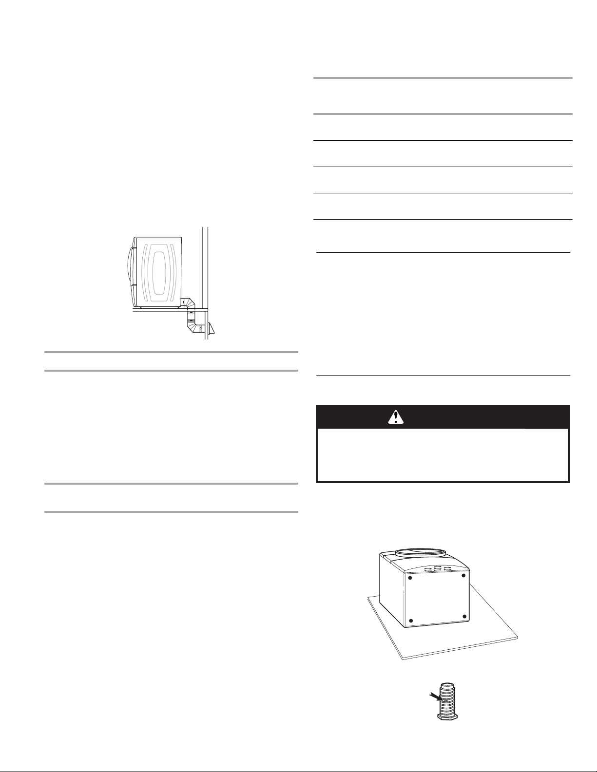
Install Leveling Legs
WARNING
Excessive Weight Hazard
Use two or more people to move and install dryer.
Failure to do so can result in back or other injury.
1. To protect the floor, use a large flat piece of cardboard from
the dryer carton. Place cardboard under the entire back edge
of the dryer.
2. Firmly grasp the body of the dryer (not the console panel).
Gently lay the dryer on the cardboard. See illustration.
16
3. Examine the leveling legs. Find the diamond marking.
Page 17
4. Screw the legs into the leg holes by hand. Use a wrench to
C
finish turning the legs until the diamond marking is no longer
visible.
5. Place a carton corner post from dryer packaging under each
of the 2 dryer back corners. Stand the dryer up. Slide the
dryer on the corner posts until it is close to its final location.
Leave enough room to connect the exhaust vent.
Connect Vent
1. Using a 4" (10.2 cm) clamp, connect vent to exhaust outlet in
dryer. If connecting to existing vent, make sure the vent is
clean. The dryer vent must fit over the dryer exhaust outlet
and inside the exhaust hood. Check that the vent is secured
to exhaust hood with a 4" (10.2 cm) clamp.
2. Move dryer into its final location. Do not crush or kink vent.
3. (On gas models) Check that there are no kinks in the flexible
gas line.
4. Once the exhaust vent connection is made, remove the
corner posts and cardboard.
Level Dryer
Check the levelness of the dryer. Check levelness first
side to side, then front to back.
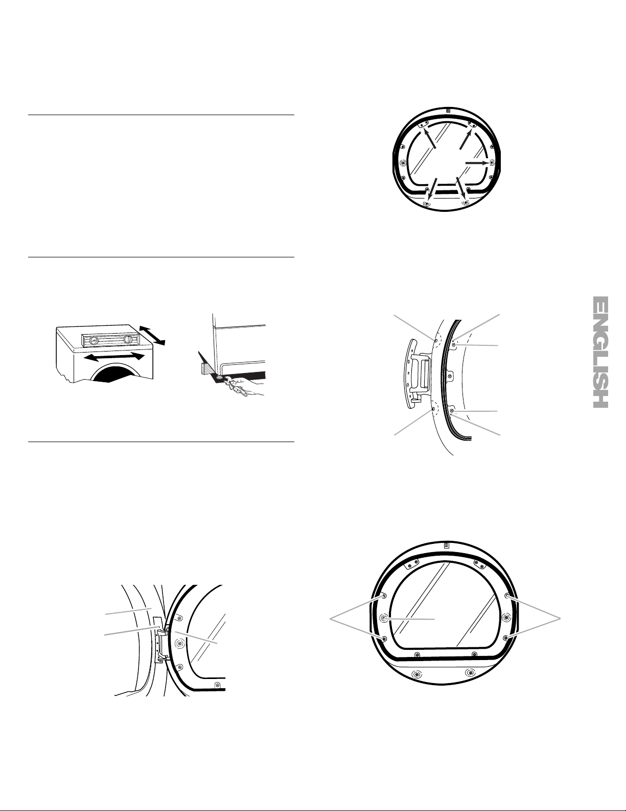
4. Lay the dryer door on a flat, protected surface with the inside
door assembly facing up.
Remove the 5 screws to release the outer door assembly
from the inner door assembly, as indicated below. See
illustration. It is important that you remove only the
5 indicated screws.
5. Lift the inner door assembly off of the outer door assembly.
Set the outer door assembly aside.
Reverse the hinge
1. Place the inner door, screw head side up, on the work space.
2. Remove the 4 hinge screws that hold the hinge to the door
and remove hinge.
A
B
If the dryer is not level, prop up the dryer using a wood block.
Use a wrench to adjust the legs up or down and check again for
levelness.
Reverse Door Swing
You can change your door swing from a right-side opening to a
left-side opening, if desired.
NOTE: For ease of installation, you may want to use 2 or more
people to remove and reattach the dryer door.
Remove the door
1. Place a towel or soft cloth on top of the dryer or work space
to protect the surface.
2. Open the dryer door. Remove the 5 screws that hold the door
hinge on the front panel of the dryer.
A
C
B
C
C
A
A. Hinge side screw
B. Locator pins on hinge
C. Top side screw
3. Move the large hole screw to the opposite side. Remove the
2 plug screws and plastic plugs, and insert them in the
original screw holes on the opposite side.
A
B
B
3. Remove the door.
A. Dryer front panel
B. Dryer door
C. Screws
A. Hinge screws
B. Large hole screw
C. Plug screws and plastic plugs
17
Page 18

4. Move hinge to the other side and reattach with the 4 screws
C
B
removed in Step 3. Make sure locator pins line up in holes
and drive the top 2 screws in place first to help drive locator
pins into proper location.
5. Set the inner door assembly aside.
Reverse the door handle
1. Place the outer door assembly face down on work space.
2. Remove the 6 screws that hold the intermediate door to the
outer door assembly. Remove the intermediate door, and set
hinge shield aside. Remove the hinge hole cover.
B
A
4. Align the door by placing the locating tabs on the hinge with
the locating holes on the dryer front panel. Insert and tighten
the center hinge screw. The door will hang in place while you
insert and tighten the remaining 4 screws.
NOTE: Two or more people may be needed to reattach the
dryer door.
A
C
A. Dryer door
B. Dryer front panel
C. Insert this hinge screw first.
5. Close the door and check that it latches securely.
6. Check for fingerprints on the glass. Clean the glass if
necessary.
A. Intermediate door
B. Hinge shield
C. Hinge hole cover
3. Rotate the window assembly 180º and reattach the
intermediate door, hinge shield and hinge hole cover with the
6 screws removed in Step 2.
Reinstalling the door
1. Place the inner door assembly into the outer door assembly.
To fit correctly, the inside door assembly edge is completely
inside the outside door assembly edge.
2. Reassemble the inner and outer door assemblies with the
5screws.
3. Remove existing label from the opposite side of the door and
discard. Find label provided with the Use and Care Guide and
apply over original hinge holes.
Complete Installation
1. Check that all parts are now installed. If there is an extra part,
go back through the steps to see which step was skipped.
2. Check that you have all of your tools.
3. Dispose of/recycle all packaging materials.
4. Check the dryer’s final location. Be sure the vent is not
crushed or kinked.
5. Check that the dryer is level. See “Level Dryer.”
6. For power supply cord installation, plug into an outlet. For
direct wire installation, reconnect power.
7. Remove the blue protective film on the console and any tape
remaining on the dryer.
8. Read “Dryer Use.”
9. Wipe the dryer drum interior thoroughly with a damp cloth to
remove any dust.
10. Select a Timed Dry heated cycle, and start the dryer. Do not
select the Air Only Temperature setting.
If the dryer will not start, check the following:
■ Controls are set in a running or “On” position.
■ Start button has been pushed firmly.
■ Dryer is plugged into an outlet and/or electrical supply
is connected.
■ Household fuse is intact and tight, or circuit breaker has
not tripped.
■ Dryer door is closed.
11. When the dryer has been running for 5 minutes, open the
dryer door and feel for heat. If you feel heat, cancel cycle and
close the door.
If you do not feel heat, turn off the dryer and check the
following:
■ There may be 2 household fuses or circuit breakers for
the dryer. Check that both fuses are intact and tight, or
that both circuit breakers have not tripped. If there is still
no heat, contact a qualified technician.
NOTE: You may notice a burning odor when the dryer is first
heated. This odor is common when the heating element is first
used. The odor will go away.
18
Page 19

DRYER USE
Starting Your Dryer
WARNING
Explosion Hazard
Keep flammable materials and vapors, such as
gasoline, away from dryer.
Do not dry anything that has ever had anything
flammable on it (even after washing).
Failure to follow these instructions can result in death,
explosion, or fire.
WARNING: To reduce the risk of fire, electric shock, or injury to
persons, read the IMPORTANT SAFETY INSTRUCTIONS before
operating this appliance.
Follow these basic steps to start your dryer. Please refer to
specific sections of this manual for more detailed information.
1. Clean lint screen before each load. See “Cleaning the Lint
Screen.”
2. Place laundry in dryer and shut door.
3. Press the POWER button. Then rotate the dial or press a
Timed Cycles button to select the desired Auto or Timed
Cycle. The preset settings for Auto Cycles or Timed Cycles
will illuminate. The estimated or actual cycle time (in minutes)
will show in the display.
To use an Auto Cycle
NOTE: A light next to each feature will glow green when the
feature is selected or will glow amber when the feature is
selectable. The light will not glow when the selection is
unavailable with the cycle or option combinations selected.
WARNING
Fire Hazard
No washer can completely remove oil.
Do not dry anything that has ever had any type of oil on
it (including cooking oils).
Items containing foam, rubber, or plastic must be dried
on a clothesline or by using an Air Cycle.
Failure to follow these instructions can result in death
or fire.
■ Select an Auto Cycle.
■ Select DRYNESS LEVEL to adjust how dry you want the
load. As the cycle runs, the control senses the dryness of
the load and adjusts the time automatically for the
selected dryness level.
NOTE: Most loads may be dried using Normal dryness
level, which is shown in bold letters on your control panel.
Normal is the energy preferred dryness level and will use
the least energy.
■ Select the desired Options.
To make changes during an Auto Cycle:
■ Press STOP once.
■ Adjust Dryness Level.
NOTE: Dryness Level selections can be made only while
using Auto Cycles. You can select a different dryness
level, depending on your load, by pressing Dryness Level
and choosing More Dry, Normal or Less Dry. Selecting
More Dry, Normal or Less Dry automatically adjusts the
sensed time needed.
19
Page 20

How Auto Dry works
SmartHeat™ improves drying performance with Auto Moisture
Sensing Plus, which advances the cycle as moisture is extracted
from clothing. A thermistor (electronic temperature sensor) and
moisture sensing strips in the dryer drum help measure the
amount of moisture in the clothes as they tumble. An electronic
control determines the load type to help save time, avoid
overdrying, and increase the accuracy of the end dryness level.
After the first 5 minutes of an automatic cycle, the estimated time
display will adjust based on the approximate load size, cycle,
dryness level selected and amount of moisture left in the clothes.
When the clothes have reached approximately 80% of the
dryness level selected, the estimated time display will adjust
again, showing the final drying time. Auto Moisture Sensing Plus
takes the guesswork out of drying time and enhances fabric care.
To use a Timed Cycle
NOTE: A light next to each feature will glow green when the
feature is selected or will glow amber when the feature is
selectable. The light will not glow when the selection is
unavailable with the cycle or option combinations selected.
■ Press a Timed Cycles button or, to select Air Fluff, rotate
the control knob to the desired cycle.
■ Press MORE TIME or LESS TIME until the desired drying
time is displayed. Tap MORE TIME or LESS TIME, and the
time will change by 1-minute intervals. Press and hold
MORE TIME or LESS TIME, and the time will change by
5-minute intervals.
NOTE: The More Time and Less Time buttons can be
used only with Timed Cycles.
■ Press TEMPERATURE until the desired temperature
glows.
NOTE: During a Timed Cycle, you can change the settings for
Time, Temperature, WRINKLE GUARD
®
and End of Cycle
Signal. Press STOP twice to stop the dryer and clear the
settings. Select another cycle or option.
4. (OPTIONAL STEP) If desired, select OPTIONS. For more
details, see “Options.”
5. (OPTIONAL STEP) If desired, set the
End of Cycle Signal
.
Select LOUD or SOFT by pressing the Cycle Signal button to
alert you when a cycle ends.
6. Press and hold START for approximately 3 seconds until
dryer starts. Be sure the door is closed.
■ If you do not press Start within 5 minutes of selecting the
cycle, the dryer automatically shuts off.
■ If you wish to end your drying cycle after pressing Start,
press Stop twice.
Stopping Your Dryer
To stop your dryer at any time
Press STOP twice or open the door.
Pausing or Restarting
To pause the dryer at any time
Open the door or press STOP once.
To restart the dryer
Close the door. Press and hold START until dryer starts.
NOTE: Drying will continue from where the cycle was interrupted
if you close the door and press START within 5 minutes. If the
cycle is interrupted for more than 5 minutes, the dryer will shut
off. Select new cycle settings before restarting the dryer.
Control Locked
This feature allows you to lock your settings to avoid unintended
use of the dryer. You can also use the Control Locked feature to
avoid unintended cycle or option changes during dryer operation.
To enable the Control Locked feature:
Press and hold CYCLE SIGNAL for 3 seconds. The Control
Locked indicator light glows, and a single beep tone is heard. To
unlock, press and hold CYCLE SIGNAL for 3 seconds. The
indicator light turns off.
Drying and Cycle Tips
Select the correct cycle and dryness level or temperature for your
load. If an Auto Cycle is running, the display shows the estimated
cycle time, which is determined by your dryer automatically
sensing the dryness level of your load. If a Timed Cycle is
running, the display shows the exact number of minutes
remaining in the cycle.
Cool Down tumbles the load without heat during the last few
minutes of all cycles. Cool Down makes the loads easier to
handle and reduces wrinkling. The length of the Cool Down
depends on the load size and dryness level.
Drying tips
■ Follow care label directions when they are available.
■ If desired, add a fabric softener sheet. Follow package
instructions.
■ To reduce wrinkling, remove the load from the dryer as soon
as tumbling stops. This is especially important for permanent
press, knits and synthetic fabrics.
■ Avoid drying heavy work clothes together with lighter fabrics.
This could cause overdrying of lighter fabrics and lead to
increased shrinkage or wrinkling.
Cycle tips
■ Dry most loads using the preset cycle settings.
■ Refer to the Auto Cycles or Timed Cycles Preset Settings
chart (in the “Cycles” section) for a guide to drying various
loads.
■ Drying temperature and Dryness Level are preset when
you choose an Auto Cycle. You can select a different
dryness level, depending on your load, by pressing
Dryness Level and choosing More Dry, Normal or Less
Dry.
NOTE: You cannot use the Timed Cycle Adjust and you
cannot modify temperature with the Auto Cycles.
■ If you wish to adjust the cycle length of a Timed Cycle,
press More Time or Less Time. Adjust the temperature of
a Timed Cycle by pressing TEMPERATURE until the
desired temperature is selected.
NOTE: You cannot use the Dryness Level with Timed
Cycles.
20
Page 21

Status Lights
You may follow the progress of your dryer with the drying Status
indicator lights.
Timed Cycle
The Timed Cycle light glows green during a Timed Cycle.
Wet
The Wet light glows green at the beginning of Auto Dry if a wet
item is detected or in a timed cycle after 5 minutes.
■ In an Auto Cycle, if a wet item is not detected after 5 minutes,
the dryer will run for a preset minimum run time (based on the
selected cycle and dryness level setting) and then go into
Cool Down. The Cool Down and WRINKLE GUARD
indicators will glow green, if selected.
■ In a Timed Cycle, the Wet light will glow green after 5 minutes
and remain on until the dryer enters Cool Down.
Damp
The Damp light glows green in an Auto Cycle when the laundry is
approximately 80% dry. This is useful when you want to remove
lightweight items in a mixed load to avoid overdrying or remove
partially dry items that may need ironing. To be alerted when the
load is about 80% dry, you may use the damp dry signal option.
See Damp Dry Signal in “Options.”
Cool Down
The Cool Down light glows green during the cool down part of
the cycle. Laundry cools for ease in handling.
Clothes Dry
The Clothes Dry light glows green when the drying cycle is
finished. This indicator stays on during WRINKLE GUARD®.
WRINKLE GUARD®
The WRINKLE GUARD® light glows green when this option is
selected. This indicator stays on with Clothes Dry.
Sensing/Revising Est. Time
The Sensing/Revising Est. Time light glows green when moisture
sensing strips in the dryer drum are measuring the amount of
moisture in the clothes. The estimated time display may adjust to
show a more accurate drying time.
®
Cycles
Select the drying cycle that matches the type of load you are
drying. See Auto Dry chart or Timed Preset Cycle Settings chart.
Auto Cycles
Auto Cycles allow you to match the cycle to the load you are
drying. See the following Auto Dry Preset Cycle Settings chart.
Each cycle dries certain fabrics at the recommended
temperature. A sensor detects the moisture in the load and
automatically adjusts the drying time for optimal drying.
Heavy Duty
Use this cycle to get high heat for heavyweight mixed loads,
cotton towels or bedspreads.
Jeans
Use this cycle to get medium high heat for drying denims.
Normal
Use this cycle to get medium heat for drying sturdy fabrics such
as work clothes and sheets.
Casual
Use this cycle to get low heat for drying no-iron fabrics, such as
sport shirts, casual business clothes and permanent press
blends.
Delicate
Use this cycle to get extra-low heat to gently dry items such as
lingerie, blouses or washable knit fabrics.
Auto Dry Preset Cycle Settings
Auto Cycles
Load Type
HEAVY DUTY
Heavyweight mixed loads,
cotton towels, bedspreads
Temperature Time*
(Minutes)
High 45
Indicator lights
Other indicator lights show Cycle, Options, Modifiers, End of
Cycle and Control Lock settings selected. The display shows the
estimated or actual time remaining.
JEANS
Denim jeans, jackets
NORMAL
Corduroys, work clothes,
sheets
CASUAL
Permanent press,
synthetics
DELICATE
Lingerie, blouses, washable
knit fabrics
*Estimated Time with Auto Dry Level (Normal) setting. Time will
vary depending on load type and load size.
Medium High 55
Medium 40
Low 35
Extra Low 30
21
Page 22

Timed Cycles
Use Timed Cycles to select a specific amount of drying time and
a drying temperature. (Temperatures are not selectable with Air
Fluff). When a Timed Cycle is selected, the Estimated Time
Remaining display shows the actual time remaining in your cycle.
You can change the actual time in the cycle by pressing More
Time or Less Time. See “Changing Cycles, Options and
Modifiers.”
Timed Dry
Use this cycle to complete drying if items are still damp after an
Auto Cycle. Timed Dry is also useful for drying heavyweight and
bulky items, such as bedspreads and work clothes. Lightweight
garments, such as exercise wear, can be dried using Timed Dry
on a low temperature setting. Timed Dry can also be used with
the Tumble Free Heated Dryer Rack.
EXPRESS DRY™
Use this cycle for drying small loads or loads that need a short
drying time.
Tou ch Up
Use this cycle to help smooth out wrinkles from items, such as
clothes packed in a suitcase or items wrinkled from being left in
the dryer too long.
Timed Preset Cycle Settings
Timed Cycles
Load Type
TIMED DRY
Heavyweight, bulky items,
bedspreads, work clothes
EXPRESS DRY™
Small loads
TOUCH UP
Helps to smooth out
wrinkles
AIR FLUFF
Dry without heat
*Use the Air Fluff cycle for items that require drying without heat
such as rubber, plastic and heat-sensitive fabrics.
Default
Temperature
Default Time
(Minutes)
High 40
High 23
Medium High 20
Air Dry
36
(no heat)
Options
You can customize your cycles by selecting options.
Air Fluff
Rotate the dial to Air Fluff to use this cycle for items that require
drying without heat such as rubber, plastic and heat-sensitive
fabrics. This table shows examples of items that can be dried
using Air Fluff. The temperature setting is not adjustable with this
cycle.
Type of Load Time*
(Minutes)
Foam rubber - pillows, padded bras, stuffed toys 20 - 30
Plastic - Shower curtains, tablecloths 20 - 30
Rubber-backed rugs 40 - 50
Olefin, polypropylene, sheer nylon 10 - 20
*Reset cycle to complete drying, if needed.
When using Air Fluff
■ Check that coverings are securely stitched.
■ Shake and fluff pillows by hand periodically during the cycle.
■ Dry item completely. Foam rubber pillows are slow to dry.
WRINKLE GUARD®
WRINKLE GUARD® helps smooth out wrinkles that form when
you cannot unload the dryer promptly at the end of a cycle.
During this option, the dryer stops tumbling and then tumbles
again for a brief period.
■ Press WRINKLE GUARD
periodic tumbling at the end of a cycle.
■ Stop WRINKLE GUARD
GUARD
■ For the Casual cycle, WRINKLE GUARD
®
or opening the dryer door.
other cycles will retain the WRINKLE GUARD® setting. For
example, if you select WRINKLE GUARD
cycle, WRINKLE GUARD
the Normal cycle.
NOTE: If you do not select WRINKLE GUARD
after cool down.
®
to get up to 2 hours of heat-free,
®
at any time by pressing WRINKLE
®
is preset to ON. The
®
®
will be on the next time you select
in the Normal
®
, the dryer stops
22
Page 23

Damp Dry Signal
Select the Damp Dry Signal to alert you that your clothes are
approximately 80% dry. This is useful when you want to remove
lightweight items in a mixed load to avoid overdrying or remove
partially dry items that may need ironing.
NOTE: The Damp Dry Signal is available only with the Auto
Cycles.
Button Sounds
You can change the volume of the sound of the beeps. Press
BUTTON SOUNDS until the desired volume (Loud, Soft or Off)
glows. The Power and Cancel buttons will still beep softly when
the Button Sounds volume is set to Off.
Drum Light
Press Drum Light to turn on the light inside the dryer drum.
During a cycle, if Drum Light is selected, the drum light turns on
and will remain on until DRUM LIGHT is pressed again, the door
is open and closed, or the door is left open for 5 minutes.
When the dryer is not running, the drum light will turn on when
DRUM LIGHT is pressed or the dryer door is opened, and it will
remain on until the dryer door has been open for 5 minutes, the
dryer door is closed or DRUM LIGHT is pressed again.
Press DRUM LIGHT at any time to turn the drum light ON or OFF.
Modifiers
Use Modifiers to select time, temperatures and dryness levels for
the Timed Cycles.
Time
Press MORE TIME or LESS TIME until the desired drying time is
displayed. The time cannot be changed with Auto Cycles.
Dryness Level
Press DRYNESS LEVEL until the desired Dryness Level is
selected. Dryness Level cannot be adjusted with Timed Cycles.
Changing Cycles, Options and Modifiers
You can change Auto Cycles, Timed Cycles, Modifiers and
Options anytime before pressing Start.
■ Three short tones sound if an unavailable combination is
selected. The last selection will not be accepted.
Changing Cycles after pressing Start
1. Press STOP twice. This ends the current cycle.
2. Select the desired cycle and options.
3. Press and hold START. The dryer starts at the beginning of
the new cycle.
NOTE: If you do not press START within 5 minutes of selecting
the cycle, the dryer automatically shuts off.
Changing Modifiers and Options after pressing Start
You can change a Modifier or Option anytime before the selected
Modifier or Option begins.
1. Press STOP once.
2. Select the new Modifier and/or Option.
3. Press and hold START to continue the cycle.
NOTE: If you happen to press Stop twice, the program clears and
your dryer shuts down. Restart the selection process.
Temperature
Press TEMPERATURE until the desired temperature setting
glows. Temperature modifiers cannot be used with the Auto
Cycles or with the Air Fluff cycle.
Changing the Preset Dryness Level Settings
If all of your loads on all Auto Dry cycles are consistently not as
dry as you would like, you may change the preset Dryness Level
settings to increase the dryness. This change will affect all of your
Auto Dry cycles.
Your Dryness Level settings can be adjusted to adapt to different
installations, environmental conditions or personal preference.
There are 3 drying settings: 1 (factory preset dryness level),
2 (slightly dryer clothes, approximately 15% more drying time)
and 3 (much dryer clothes, approximately 30% more drying
time).
1. The Dryness Level settings cannot be changed while the
dryer is running.
2. Press and hold the DRYNESS LEVEL button for 5 seconds.
The dryer will beep, and “CF” will be displayed for 1 second
followed by the current drying setting.
3. To select a new drying setting, press the DRYNESS LEVEL
button again until the desired drying setting is shown.
NOTE: While cycling through the settings, the current setting
will not flash, but the other settings will flash.
4. Press START to save the drying setting.
The drying setting you selected will become your new preset
drying setting for all Auto Dry cycles.
23
Page 24

End of Cycle Signal
End of Cycle Signal
The End of Cycle Signal produces an audible sound when the
drying cycle is finished. Promptly removing clothes at the end of
the cycle reduces wrinkling.
Press CYCLE SIGNAL to adjust the sound level or turn off the
signal.
NOTE: When WRINKLE GUARD
Cycle Signal is on, a tone sounds every 5 minutes until the
clothes are removed, or WRINKLE GUARD
®
is selected and the End of
®
ends.
TUMBLE FREE™ Heated Dryer Rack
The dryer rack is shipped in place in your dryer. Remove and
discard any packing material before use.
Use the TUMBLE FREE™ Heated Dryer Rack for items that you
do not want to tumble dry, such as sweaters. When you use the
heated dryer rack, the heated air inside the dryer flows in a
concentrated pattern to allow efficient and uniform drying.
The dryer rack is recommended for use with the Air Fluff cycle or
with Timed Dry cycles. The dryer rack cannot be used with Auto
cycles.
To use the heated dryer rack:
Do not remove the lint screen.
1. Open dryer door.
2. Place dryer rack over the bottom of the dryer door opening.
Rest the back wire on the dryer back ledge. Push down on
the frame front to secure over lint screen.
3. Place wet items on top of the rack. Allow space around items
for air to circulate. The rack does not move, but the drum will
rotate. Make sure items do not hang over the edges or
between rack grille.
4. Close the door.
5. Rotate the dial to the Air Fluff cycle or press Timed Dry.
Select a drying time by pressing MORE TIME or LESS TIME.
Press TEMPERATURE until the desired temperature glows.
Items containing foam, rubber or plastic must be dried on a
clothesline or by using the Air Fluff cycle. Refer to the
following table.
6. When Air Fluff is selected, the Estimated Time Remaining
display shows the default time. You can change the actual
time in the cycle by pressing More Time or Less Time.
7. Start the dryer.
NOTE: Check the lint screen and remove any lint accumulated
from items dried on the rack after the cycle is finished.
Dryer Rack Cycle Temp. Time*
Wool Sweaters
Block to shape and lay flat
on the rack
Timed Dry Low 60
24
Stuffed toys or pillows
Cotton or polyester fiber
filled
Stuffed toys or pillows
Foam rubber filled
Sneakers or canvas
shoes
*Reset cycle to complete drying if needed.
NOTE: You must remove rack for normal tumbling. To remove the
dryer rack, lift it straight up and out of the dryer.
Timed Dry Low 60
Air Fluff Air Only
(no heat)
Air Fluff Air Only
(no heat)
90
90
Page 25

DRYER CARE
Cleaning the Dryer Location
Keep dryer area clear and free from items that would obstruct the
flow of combustion and ventilation air.
WARNING
To wash
1. Roll lint off the screen with your fingers.
2. Wet both sides of lint screen with hot water.
3. Wet a nylon brush with hot water and liquid detergent. Scrub
lint screen with the brush to remove residue buildup.
Explosion Hazard
Keep flammable materials and vapors, such as
gasoline, away from dryer.
Place dryer at least 18 inches (46 cm) above the floor
for a garage installation.
Failure to do so can result in death, explosion, or fire.
Cleaning the Lint Screen
Every load cleaning
The lint screen is located in the door opening of the dryer. The
control panel has an indicator light to remind you to clean the lint
screen before each load. A screen blocked by lint can increase
drying time.
To clean
1. Pull the lint screen straight up. Roll lint off the screen with
your fingers. Do not rinse or wash screen to remove lint. Wet
lint is hard to remove.
2. Push the lint screen firmly back into place.
IMPORTANT:
■ Do not run the dryer with the lint screen loose, damaged,
blocked, or missing. Doing so can cause overheating and
damage to both the dryer and fabrics.
■ If lint falls off the screen into the dryer during removal, check
the exhaust hood and remove the lint. See “Venting
Requirements.”
As needed cleaning
Laundry detergent and fabric softener residue can build up on the
lint screen. This buildup can cause longer drying times for your
clothes, or cause the dryer to stop before your load is completely
dry. The screen is probably clogged if lint falls off while the screen
is in the dryer.
Clean the lint screen with a nylon brush every 6 months, or more
frequently, if it becomes clogged due to a residue buildup.
4. Rinse screen with hot water.
5. Thoroughly dry lint screen with a clean towel. Replace screen
in dryer.
Cleaning the Dryer Interior
To clean dryer drum
1. Make a paste with powdered laundry detergent and very
warm water.
2. Apply paste to a soft cloth.
OR
Apply a liquid, nonflammable household cleaner to the
stained area and rub with a soft cloth until all excess dye and
stains are removed.
3. Wipe drum thoroughly with a damp cloth.
4. Tumble a load of clean cloths or towels to dry drum.
NOTE: Garments that contain unstable dyes, such as denim blue
jeans or brightly colored cotton items, may discolor the dryer
interior. These stains are not harmful to your dryer and will not
stain future loads of clothes. Dry unstable dye items inside out to
avoid dye transfer.
Removing Accumulated Lint
From Inside the Dryer Cabinet
Lint should be removed every 2 years, or more often, depending
on dryer usage. Cleaning should be done by a qualified person.
From the Exhaust Vent
Lint should be removed every 2 years, or more often, depending
on dryer usage.
Vacation and Moving Care
Vacation care
Operate your dryer only when you are at home. If you will be on
vacation or not using your dryer for an extended period of time,
you should:
1. Unplug dryer or disconnect power.
2. Clean lint screen. See “Cleaning the Lint Screen.”
25
Page 26

Moving care
For power supply cord-connected dryers:
1. Unplug the power supply cord.
2. Make sure leveling legs are secure in dryer base.
3. Use masking tape to secure dryer door.
For direct-wired dryers:
WARNING
Electrical Shock Hazard
Disconnect power before servicing.
Replace all parts and panels before operating.
Failure to do so can result in death or electrical shock.
1. Disconnect power.
2. Disconnect wiring.
3. Make sure leveling legs are secure in dryer base.
4. Use masking tape to secure dryer door.
Changing the Drum Light
The dryer light automatically turns on inside the dryer drum when
you open the door.
To change the drum light
1. Unplug dryer or disconnect power.
2. Open the dryer door. Locate the light bulb cover on the back
wall of the dryer. Remove the screw located in the lower right
corner of the cover. Remove the cover.
3. Turn bulb counterclockwise. Replace the bulb with a 10-watt
appliance bulb only. Replace the cover and secure with the
screw.
4. Plug in dryer or reconnect power.
TROUBLESHOOTING
First try the solutions suggested here and possibly avoid the cost of a service call...
Dryer Operation
Dryer will not run
■ Has a fuse blown, or has a circuit breaker tripped?
There may be 2 fuses or circuit breakers for the dryer. Check
that both fuses are intact and tight, or that both circuit
breakers have not tripped. Replace the fuse or reset the
circuit breaker. If the problem continues, call an electrician.
■ Is the correct power supply available?
Electric dryers require 240-volt power supply. Check with a
qualified electrician.
■ Was a regular fuse used?
Use a time-delay fuse.
■ Is the dryer door firmly closed?
■ Was the Start button firmly pressed?
Large loads may require pressing and holding the Start
button for 2-5 seconds.
No heat
■ Has a fuse blown, or has a circuit breaker tripped?
The drum may be turning, but you may not have heat. Electric
dryers use 2 fuses or circuit breakers. Replace the fuse or
reset the circuit breaker. If the problem continues, call an
electrician.
Unusual sounds
■ Has the dryer had a period of non-use?
If the dryer hasn’t been used for a while, there may be a
thumping sound during the first few minutes of operation.
■ Is a coin, button, or paper clip caught between the drum
and front or rear of the dryer?
Check the front and rear edges of the drum for small objects.
Clean out pockets before laundering.
■ Are the four legs installed, and is the dryer level front to
back and side to side?
The dryer may vibrate if not properly installed. See the
Installation Instructions.
■ Is the clothing knotted or balled up?
When balled up, the load will bounce, causing the dryer to
vibrate. Separate the load items and restart the dryer.
Dryer displaying code message
■ “PF” (power failure), check the following:
Was the drying cycle interrupted by a power failure?
Press and hold START to restart the dryer.
■ “F” Variable (F1, F2, F20) service codes:
Call for service.
26
Page 27

Dryer Results
Clothes are not drying satisfactorily, drying times are too
long, or load is too hot
■ Is the lint screen clogged with lint?
Lint screen should be cleaned before each load.
WARNING
Fire Hazard
Use a heavy metal vent.
Do not use a plastic vent.
Do not use a metal foil vent.
Failure to follow these instructions can result in death
or fire.
■ Is the dryer located in a closet?
Closet doors must have ventilation openings at the top and
bottom of the door. The front of the dryer requires a minimum
of 1" (2.5 cm) of airspace, and, for most installations, the rear
of the dryer requires 5" (12.7 cm). See “Installation
Instructions.”
■ Has an air dry cycle been selected?
Select the right cycle for the types of garments being dried.
See “Modifiers.”
■ Is the load too large and heavy to dry quickly?
Separate the load to tumble freely.
Cycle time too short
WARNING
Excessive Weight Hazard
Use two or more people to move and install dryer.
Failure to do so can result in back or other injury.
■ Is the exhaust vent or outside exhaust hood clogged with
lint, restricting air movement?
Run the dryer for 5-10 minutes. Hold your hand under the
outside exhaust hood to check air movement. If you do not
feel air movement, clean exhaust system of lint or replace
exhaust vent with heavy metal or flexible metal vent. See
“Venting Requirements.”
■ Are fabric softener sheets blocking the lint screen grille?
Use only one fabric softener sheet, and use it only once.
■ Is the exhaust vent the correct length?
Check that the exhaust vent is not too long or has too many
turns. Long venting will increase drying times. See “Plan Vent
System.”
■ Is the exhaust vent diameter the correct size?
Use 4" (10.2 cm) diameter vent material.
WARNING
Explosion Hazard
Keep flammable materials and vapors, such as
gasoline, away from dryer.
Place dryer at least 18 inches (46 cm) above the floor
for a garage installation.
Failure to do so can result in death, explosion, or fire.
■ Is the dryer located in a room with temperature below
45ºF (7ºC)?
Proper operation of dryer cycles requires temperatures above
45ºF (7ºC).
■ Is the automatic cycle ending early?
The load may not be contacting the sensor strips. Level the
dryer.
Change the dryness level setting on Automatic Cycles.
Increasing or decreasing the dryness level will change the
amount of drying time in a cycle.
Do not use a dryer rack with an automatic cycle.
Lint on load
■ Is the lint screen clogged?
Clean lint screen. Check for air movement.
Stains on load or drum
■ Was dryer fabric softener properly used?
Add dryer fabric softener sheets at the beginning of the cycle.
Fabric softener sheets added to a partially dried load can
stain your garments.
Drum stains are caused by dyes in clothing (usually blue
jeans). This will not transfer to other clothing.
Loads are wrinkled
■ Was the load removed from dryer at the end of the cycle?
■ Was the dryer overloaded?
Dry smaller loads that can tumble freely.
Odors
■ Have you recently been painting, staining or varnishing in
the area where your dryer is located?
If so, ventilate the area. When the odors or fumes are gone
from the area, rewash and dry the clothing.
■ Is the dryer being used for the first time?
The new electric heating element may have an odor. The odor
will be gone after the first cycle.
27
Page 28

ÍNDICE
CONTRATOS DE
CONTRATOS DE PROTECCIÓN................................................ 28
GARANTÍA.................................................................................... 29
SEGURIDAD DE LA SECADORA ............................................... 30
INSTRUCCIONES DE INSTALACIÓN........................................ 31
Herramientas y piezas............................................................... 31
Pedestal opcional...................................................................... 31
Requisitos de ubicación ........................................................... 31
Requisitos eléctricos ................................................................. 33
Conexión eléctrica..................................................................... 35
Requisitos de ventilación .......................................................... 40
Planificación del sistema de ventilación ................................... 41
Instalación del sistema de ventilación ...................................... 42
Instalación de las patas niveladoras......................................... 43
Conexión del ducto de escape ................................................. 43
Nivelación de la secadora ......................................................... 43
Inversión del cierre de la puerta................................................ 43
Complete la instalación............................................................. 45
USO DE LA SECADORA ............................................................. 46
Puesta en marcha de la secadora ............................................ 46
Detención de la marcha de la secadora ................................... 47
Pausa o reanudación de la marcha .......................................... 47
Control bloqueado..................................................................... 47
Sugerencias de ciclos y secado ............................................... 47
Luces de estado........................................................................ 48
Ciclos......................................................................................... 48
Opciones ................................................................................... 50
Modificadores............................................................................ 50
Cambio de ciclos, opciones y modificadores........................... 51
Señal de fin de ciclo .................................................................. 51
Estante térmico de la secadora TUMBLE FREE™................... 51
CUIDADO DE LA SECADORA.................................................... 52
Limpieza del lugar donde está la secadora .............................. 52
Limpieza del filtro de pelusa...................................................... 52
Limpieza del interior de la secadora ......................................... 53
Eliminación de pelusa acumulada ............................................ 53
Cuidado para las vacaciones y la mudanza ............................. 53
Cambio de la luz del tambor ..................................................... 53
SOLUCIÓN DE PROBLEMAS..................................................... 54
NÚMEROS DE SERVICIO ..............................CONTRAPORTADA
PROTECCIÓN
Contratos Maestros de Protección
¡Felicitaciones por su inteligente adquisición! Su nuevo producto
Kenmore
funcionamiento confiable. Pero al igual que todos los productos,
puede necesitar mantenimiento preventivo o reparación de vez
en cuando. Es allí donde el Contrato Maestro de Protección
puede ahorrarle dinero e inconvenientes.
Adquiera un Contrato Maestro de Protección hoy y protéjase
contra molestias y gastos inesperados.
El Contrato Maestro de Protección también ayuda a prolongar la
vida de su nuevo producto. He aquí lo que se incluye en el
Contrato:
✔ Servicio experto por nuestros 12.000 especialistas en
✔ Servicio ilimitado y gratuito para repuestos y mano de obra
✔ Garantía “sin disgustos” - reemplazo de su producto
✔ Reemplazo del producto si su producto protegido no puede
✔ Revisión Anual de Mantenimiento Preventivo a solicitud
✔ Ayuda rápida por teléfono - asistencia por teléfono a cargo
✔ Protección de sobrevoltaje contra daños eléctricos debido a
✔ Reembolso de la renta si la reparación de su producto
Una vez adquirido el Contrato, tan sólo tiene que llamar para fijar
la visita de servicio técnico. Usted puede llamar a cualquier hora,
de día o de noche, o fijar una visita técnica en internet.
Sears cuenta con un equipo de más de 12.000 especialistas en
reparación competentes, quienes tienen a disposición más de
4,5 millones de repuestos y accesorios de calidad. Ése es el tipo
de profesionalismo con el que usted puede contar para ayudarle
a prolongar la vida de su nuevo artefacto por muchos años más.
¡Adquiera hoy su Contrato Maestro de Protección!
Se aplican algunas limitaciones y exclusiones. Para obtener
precios e información adicional, llame al 1-800-827-6655.
®
ha sido diseñado y fabricado para brindarle años de
reparación competentes
en todas las reparaciones protegidas por el contrato
protegido si ocurren cuatro o más fallas del producto en el
transcurso de doce meses
ser reparado
suya - sin costo adicional
de un técnico de Sears para productos que deban ser
reparados en su hogar, además de un horario de reparación
conveniente
fluctuaciones de electricidad
protegido tarda más de lo prometido
28
Servicio de Instalación de Sears
Para la instalación profesional de Sears de artefactos
electrodomésticos, abridores de puertas de garaje, calentadores
de agua y otros artículos importantes de la casa, en los EE.UU.
llame al 1-800-4-MY-HOME
®
.
Page 29

GARANTÍA DE LOS ELECTRODOMÉSTICOS
KENMORE ELITE®
GARANTÍA LIMITADA DE UN AÑO
Cuando este electrodoméstico haya sido instalado, operado y
mantenido según las instrucciones provistas con el producto, si
este electrodoméstico falla por defectos de material o de mano
de obra dentro de un año a partir de la fecha de compra, llame al
1-800-4-MY-HOME
GARANTÍA LIMITADA DE DOS AÑOS PARA EL TABLERO
ELECTRÓNICO SENSOR SMART™
Durante dos años a partir de la fecha de compra, siempre y
cuando esta secadora haya sido instalada, operada y mantenida
de conformidad con todas las instrucciones provistas con el
producto, Sears reemplazará el tablero de control electrónico si
tuviera defectos en los materiales o en la mano de obra. Después
del primer año, el cliente asume la responsabilidad por cualquier
costo de mano de obra relativa al reemplazo de estas
refacciones.
Si este electrodoméstico es empleado para algún otro uso que
no sea el doméstico familiar, esta garantía sólo tiene vigencia por
90 días a partir de la fecha de compra.
ESTA GARANTÍA CUBRE SOLAMENTE LOS DEFECTOS DE
MATERIAL Y MANO DE OBRA. SEARS NO PAGARÁ POR LO
SIGUIENTE:
1. Los artículos no reutilizables que pueden gastarse por el uso
normal, incluyendo, pero sin limitación, filtros, correas, focos
y bolsas.
2. Un técnico de servicio para enseñarle al usuario cómo
instalar, operar o mantener el producto adecuadamente.
3. Un técnico de servicio para limpiar o mantener este
producto.
4. Daños a este producto o fallas del mismo en caso de no ser
instalado, operado o mantenido conforme a todas las
instrucciones provistas con el producto.
5. Daños a este producto o fallas del mismo como resultado de
accidente, abuso, uso indebido o un uso diferente de aquel
para el cual fue creado.
6. Daños a este producto o fallas del mismo causados por el
uso de detergentes, limpiadores, productos químicos o
utensilios diferentes de los recomendados en todas las
instrucciones provistas con el producto.
7. Daños a piezas o sistemas o fallas de los mismos como
resultado de modificaciones no autorizadas que se hayan
efectuado en este producto.
®
para gestionar la reparación libre de cargo.
EXCLUSIÓN DE GARANTÍAS IMPLÍCITAS; LIMITACIÓN DE
RECURSOS
El único y exclusivo recurso del cliente según los términos de
esta garantía limitada será el de reparar el producto según se
estipula en la presente. Las garantías implícitas, incluyendo las
garantías de comerciabilidad o de capacidad para un propósito
particular, serán limitadas a un año o al período más corto
permitido por ley. Sears no se hará responsable por daños
incidentales o consecuentes. Algunos estados y provincias no
permiten la exclusión o limitación de daños incidentales o
consecuentes, o limitaciones acerca de cuánto debe durar una
garantía implícita de comerciabilidad o capacidad, de modo que
las limitaciones o exclusiones arriba mencionadas pueden no
aplicarse en su caso.
Esta garantía se aplica sólo mientras este electrodoméstico se
usa en los Estados Unidos y Canadá.
Esta garantía le otorga derechos legales específicos, y es posible
que usted tenga también otros derechos, los cuales varían de un
estado a otro.
Sears, Roebuck and Co.
Dept. 817WA, Hoffman Estates, IL 60179
Sears Canada Inc.
Toronto, Ontario, Canada M5B 2B8
REGISTRO DEL PRODUCTO
En el espacio a continuación, anote el número completo de
modelo y serie así como la fecha de compra. Usted puede
encontrar esta información en la etiqueta con el número de
modelo y de serie ubicada en el producto.
Tenga esta información disponible para facilitarle la obtención de
asistencia o servicio con prontitud siempre que llame a Sears
con respecto a su electrodoméstico.
Número de modelo __ __ __. _____________________________________
Número de serie ________________________________________________
Fecha de compra _______________________________________________
Guarde estas instrucciones y su comprobante de compra
para referencia futura.
29
Page 30

SEGURIDAD DE LA SECADORA
Su seguridad y la seguridad de los demás es muy importante.
Hemos incluido muchos mensajes importantes de seguridad en este manual y en su electrodoméstico. Lea y obedezca siempre
todos los mensajes de seguridad.
Este es el símbolo de advertencia de seguridad.
Este símbolo le llama la atención sobre peligros potenciales que pueden ocasionar la muerte o una lesión a
usted y a los demás.
Todos los mensajes de seguridad irán a continuación del símbolo de advertencia de seguridad y de la palabra
“PELIGRO” o “ADVERTENCIA”. Estas palabras significan:
PELIGRO
ADVERTENCIA
Todos los mensajes de seguridad le dirán el peligro potencial, le dirán cómo reducir las posibilidades de sufrir una lesión y lo que
puede suceder si no se siguen las instrucciones.
Si no sigue las instrucciones de inmediato, usted puede
morir o sufrir una lesión grave.
Si no sigue las instrucciones, usted puede morir o sufrir
una lesión grave.
INSTRUCCIONES IMPORTANTES DE SEGURIDAD
A fin de reducir el riesgo de incendio, descarga eléctrica o de daño a las personas que usen
ADVERTENCIA:
la secadora, deben seguirse las precauciones básicas, incluidas las siguientes:
■ Lea todas las instrucciones antes de usar la secadora.
■ No coloque los objetos expuestos a aceite para cocinar
en su secadora. Los objetos expuestos a aceites para
cocinar pueden contribuir a una reacción química que
podría causar que una carga se inflame.
■ No seque artículos que ya se hayan limpiado, lavado,
remojado o manchado con gasolina, disolventes de
limpieza en seco, u otras sustancias inflamables o
explosivas ya que despiden vapores que pueden
encenderse o causar una explosión.
■ No permita que jueguen los niños sobre o dentro de la
secadora. Es necesaria la cuidadosa vigilancia de los
niños toda vez que se use la secadora cerca de ellos.
■ Quite la puerta de la secadora al compartimiento de secado
antes de ponerla fuera de funcionamiento o de descartarla.
■ No introduzca las manos en la secadora cuando el tambor
está en movimiento.
■ No instale o almacene esta secadora donde estará
expuesta a agua o a la intemperie.
■ No trate de forzar los controles.
■ No repare o reemplace ninguna pieza de la secadora ni
trate de repararla a menos que esto se recomiende
especificamente en el Manual del propietario o en
instrucciones de reparación publicadas para el usuario
que usted comprenda y sólo si cuenta con la experiencia
necesaria para llevar a cabo dicha reparación.
■ No utilice suavizadores de tejidos o productos para eliminar
el estático de prendas a menos que lo recomiende el
fabricante del suavizador de tejidoso las instrucciones del
producto en uso.
■ No utilice calor para secar prendas que contengan espuma
de caucho o materiales de caucho con textura similar.
■ Limpie el filtro de pelusa antes o depués de cada carga
de ropa.
■ Mantenga el área alrededor de la apertura de ventilación
y las áreas adyacentes a esta apertura sin pelusa, polvo
o tierra.
■ La parte interior de la secadora y el ducto de escape se
deben limpiar periódicamente. Esta limpieza la debe llevar
a cabo un reparador calificado.
■ Vea la instrucciones de instalación para los requisitos de
conexión a tierra.
30
GUARDE ESTAS INSTRUCCIONES
Page 31

INSTRUCCIONES DE INSTALACIÓN
Herramientas y piezas
Reúna las herramientas y piezas necesarias antes de comenzar
la instalación. Lea y siga las instrucciones provistas con
cualquiera de las herramientas enlistadas aquí.
■ Destornillador de hoja
plana
■ Destornillador Phillips # 2
■ Llave de tuercas ajustable
que se abra a 1" (2,54 cm)
o una llave de cubo de
cabeza hexagonal (para
regular las patas de la
secadora)
■ Desforrador de alambre
(instalaciones de cableado
directo)
Piezas suministradas
Retire el paquete de piezas del tambor de la secadora. Verifique
que estén todas las piezas.
■ Nivel
■ Abrazaderas para ducto
■ Pistola y masilla para
calafateo (para instalar el
nuevo ducto de escape)
■ Tijeras de lata
(instalaciones del nuevo
ducto de escape)
■ Llave para tuercas de ¼" o
llave de cubo (se
recomienda)
■ Cinta para medir
Para realizar una instalación en el garage, necesitará ubicar el
pedestal de 10" (25,4 cm) al menos 9" (22,9 cm) por encima del
piso. Necesitará ubicar el pedestal de 15,5" (39,4 cm) al menos
3" (7,6 cm) por encima del piso.
Pedestal opcional (se muestra el modelo de 15,5" [39,4 cm])
Para hacer su pedido, llame a la tienda local de Sears. Para
obtener más información, sírvase llamar al 1-800-4-MY-HOME
(1-800-469-4663).
Altura del pedestal Color Número de
pieza
10" (25,4 cm) Blanco 46822
15,5" (39,4 cm) Blanco 57822
Requisitos de ubicación
®
4 patas niveladoras
NOTA: No use patas niveladoras si va a instalar la secadora
sobre un pedestal.
Piezas para adquirir
Verifique los códigos locales; verifique el suministro eléctrico
existente y la ventilación y vea “Requisitos eléctricos” y
“Requisitos de ventilación” antes de comprar las piezas.
■ Para instalaciones de espacio limitado entre 31,5" (80,01 cm)
y 37" (93,98 cm), vea la sección “Planificación del sistema de
ventilación” para obtener los requisitos de ventilación.
37"
(93,98 cm)
Las instalaciones en casas rodantes necesitan artículos de
ferretería para sistemas de ventilación de metal que se pueden
comprar en su tienda Sears o en el centro de servicio técnico
Sears de su localidad. Para más información, llame por favor al
1-800-4-MY-HOME
®
(1-800-469-4663).
Pedestal opcional
¿Va a colocar la secadora en un pedestal? Usted tiene la opción
de comprar por separado pedestales de alturas diferentes para
esta secadora. Puede seleccionar un pedestal de 10" (25,4 cm) o
uno de 15,5" (39,4 cm) con un cajón de almacenamiento. El
pedestal se agregará a la altura total de la secadora para llegar a
una altura total de aproximadamente 46" (116,8 cm) ó
51,5" (130,8 cm), respectivamente.
ADVERTENCIA
Peligro de Explosión
Mantenga los materiales y vapores inflamables, como
la gasolina, lejos de la secadora.
Coloque la secadora a un mínimo de 46 cm sobre
el piso para la instalación en un garaje.
No seguir estas instrucciones puede ocasionar
la muerte, explosión o incendio.
Usted necesitará
■ Una ubicación que permita una instalación adecuada del
ducto de escape. Consulte “Requisitos de ventilación”.
■ Un circuito separado de 30 amperios.
■ Si está usando un cable de suministro de energía, un
contacto con conexión a tierra ubicado a unos 2 pies (61 cm)
de cualquiera de los lados de la secadora. Vea “Requisitos
eléctricos”.
■ Un piso resistente para soportar la secadora con un peso
total de 200 lbs (90,7 kgs). Asimismo se debe considerar el
peso de otro artefacto que la acompañe.
31
Page 32

■ Un piso nivelado con un declive máximo de 1" (2,5 cm)
debajo de la secadora completa. (Si el declive es mayor que
1" [2,5 cm], instale el juego de extensión de patas de la
secadora, Pieza No. 279810.) La ropa quizás no rote
adecuadamente y los ciclos del sensor automático
posiblemente no funcionen debidamente si la secadora no
está nivelada.
■ Para la instalación en un garaje, tendrá que colocar la
secadora a una altura mínima de 18" (46 cm) encima del piso.
Si va a usar un pedestal, necesitará 18" (46 cm) hasta la parte
inferior de la secadora.
No ponga a funcionar su secadora en temperaturas que sean
inferiores a 45ºF (7ºC). A temperaturas inferiores, es posible que
la secadora no se apague al final de un ciclo automático. Los
tiempos de secado pueden prolongarse.
No debe instalarse ni guardarse la secadora en un área en donde
pueda estar expuesta al agua y/o a la intemperie.
Verifique los requisitos de los códigos. Algunos códigos limitan, o
no permiten, la instalación de la secadora en garajes, clósets,
casas rodantes o en dormitorios. Póngase en contacto con el
inspector de construcciones de su localidad.
Instalación personalizada debajo del mostrador – Sólo
secadora
0"
(0 cm)
38" mín.
(96,52 cm)
1"*
(2,5 cm)
27"
(68,6 cm)
1"*
(2,5 cm)
*Espacio necesario
Instalación en el clóset – Sólo secadora
3"*
14" máx.*
(35,6 cm)
18" mín.*
(45,72 cm)
48
pulg.
(310 cm2)
2*
(7,6 cm)
Espacios para la instalación
La ubicación debe ser lo suficientemente grande para poder abrir
completamente la puerta de la secadora.
Dimensiones de la secadora
50½"
(128,27 cm)
38"
(96,52 cm)
*31½"
(80,01 cm)
27"
(68,6 cm)
*La mayoría de las instalaciones requieren un espacio libre
mínimo de 5" (12,7 cm) detrás de la secadora para acomodar el
ducto de escape con codo. Vea “Requisitos de ventilación”.
Espacio para la instalación en un lugar empotrado o en un
clóset
Se recomiendan las siguientes medidas de espacio para esta
secadora. Esta secadora ha sido puesta a prueba para espacios
de 0" (0 cm) en los costados y en la parte posterior. El espacio
recomendado debe ser considerado por los siguientes motivos:
■ Debe considerarse el espacio adicional para facilitar la
instalación y el servicio técnico.
■ Se podrían necesitar espacios libres adicionales para las
molduras de la pared, de la puerta y del piso.
■ Se recomienda un espacio adicional en todos los lados de la
secadora para reducir la transferencia de ruido.
■ Para la instalación en clóset, con una puerta, se requieren
aberturas de ventilación mínimas en la parte superior e
inferior de la puerta. Se aceptan puertas tipo persianas con
aberturas de ventilación equivalentes.
■ También se debe considerar espacio adicional para otro
electrodoméstico que le acompañe.
2*
24
pulg.
1"*
(25 cm)
31½"
(80 cm)
A
5"**
(12,7 cm)
(155 cm2)
3"*
(7,6 cm)
B
A. Vista lateral - clóset o lugar confinado
B. Puerta del clóset con orificios de ventilación
*Espacio necesario
**Para la ventilación lateral o por la parte inferior, se permite 0"
(0 cm) de espacio.
Instalación empotrada o en el clóset – Secadora sobre el
pedestal
14" máx.*
(35,6 cm)
18" mín.*
(45,72 cm)
1"
(2,5 cm)
27"
(68,6 cm)
A
1"
(2,5 cm)
1"*
(2,5 cm)
31¹⁄₂"
(80 cm)
B
**
5"
(12,7 cm)
A. Lugar empotrado
B. Vista lateral - clóset o lugar confinado
*Espacio necesario
**Para la ventilación lateral o por la parte inferior, se permite 0"
(0 cm) de espacio.
32
Page 33

Espacio para la instalación en un armario
■ Para la instalación en el gabinete con puerta, se requieren las
aberturas de ventilación mínimas en la parte superior.
7"* (17,8 cm)
7"* (17,8 cm)
9"*
(22,9 cm)
Requisitos de instalación adicionales para las casas
rodantes
Esta secadora es apropiada para instalaciones en casas
rodantes. La instalación debe ajustarse al Estándar de seguridad
y construcción de casas fabricadas, Título 24 CFR, Parte 3280
(anteriormente conocido como Estándar federal para la
seguridad y construcción de casas rodantes, Título 24, HUD
Parte 280).
Las instalaciones en casas rodantes necesitan:
■ Artículos de ferretería para sistemas de ventilación de metal
que se pueden comprar en su tienda Sears o en el centro de
servicio técnico Sears de su localidad.
■ Se deben tomar medidas especiales en el caso de casas
rodantes para introducir el aire del exterior en la secadora. La
abertura (como la de una ventana adyacente) deberá ser por
lo menos el doble de tamaño que la abertura de ventilación
de la secadora.
Requisitos eléctricos
31¹⁄₂"
(80,0 cm)
1"*
(2,5 cm)
1"
(2,5 cm)
27"
(68,6 cm)
1"
(2,5 cm)
5"**
(12,7 cm)
*Espacio necesario
**Para la ventilación lateral o por la parte inferior, se permite 0"
(0 cm) de espacio.
Recomendaciones de espacios de instalación para
instalación empotrada o en armario, con lavadora y
secadora apiladas
Las dimensiones que se muestran son para los espacios
recomendados.
48 pulg.2 *
(310 cm2)
3"* (7,6 cm)
3"* (7,6 cm)
2
*
24 pulg.
(155 cm2)
*Espacio necesario
6"* (15,2 cm)
1"* (2,5 cm)
Usted es responsable de
■ Ponerse en contacto con un instalador eléctrico calificado.
■ Asegurarse de que la conexión eléctrica sea adecuada y de
conformidad con el Código Nacional Eléctrico, ANSI/NFPA
70 - última edición y con todos los códigos y ordenanzas
locales.
El Código Nacional Eléctrico requiere una conexión de
suministro eléctrico de 4 hilos para aquellos hogares
construidos después de 1996, para los circuitos de secadora
que se hayan reformado después de 1996 y todas las
instalaciones de casas rodantes.
Usted puede obtener una copia de todas las normas arriba
indicadas en:
National Fire Protection Association, One Batterymarch Park,
Quincy, MA 02269.
■ Proveer el suministro eléctrico requerido de 3 ó 4 alambres,
monofásico, de 120/240 voltios, 60 Hz, CA solamente (o un
suministro eléctrico de 3 ó 4 alambres, de 120/208 voltios, si
se especifica en la placa indicadora de corriente/de la serie)
en un circuito separado de 30 amperios, protegido con
fusibles en ambos lados de la línea. Se recomienda un fusible
retardador o un cortacircuitos. Conéctela a un circuito
derivado individual. No tenga un fusible en el circuito neutro o
de conexión a tierra.
■ No use un cable eléctrico de extensión.
■ Si los códigos lo permiten y se emplea un alambre de
conexión a tierra separado, es recomendable que un
electricista calificado determine si la trayectoria de conexión
a tierra es adecuada.
5"*
(12,7 cm)
*Espacio necesario
76"
(193 cm)
1"
(2,5 cm)
27"
(68,6 cm)
1"
(2,5 cm)
33
Page 34

Conexión eléctrica
Para instalar su secadora adecuadamente, usted debe
determinar el tipo de conexión eléctrica que va a usar y seguir las
instrucciones que aquí se proveen para el caso.
■ Si los códigos locales no permiten la conexión de un
conductor para conexión a tierra del equipo al alambre
neutro, vea la sección “Conexión opcional de 3 hilos”.
■ Esta secadora ha sido manufacturada lista para ser instalada
en una conexión de suministro de energía eléctrica de 3 hilos.
El hilo neutro de puesta a tierra está permanentemente
conectado al conductor neutral (cable blanco) dentro de la
secadora. Si la secadora está instalada con una conexión de
suministro eléctrico de 4 hilos, el hilo neutro de puesta a
tierra se debe quitar del tornillo de puesta a tierra exterior
(tornillo verde) y ajustar debajo del terminal neutral (cable
central o blanco) del bloque de terminal. Cuando el hilo
neutro de puesta a tierra esté ajustado debajo del terminal
neutral (cable central o blanco) del bloque de terminal, el
gabinete de la secadora queda aislado del conductor neutral.
■ Deberá usarse una conexión con suministro de energía de
4 hilos cuando el aparato esté instalado en una ubicación en
la cual esté prohibida la conexión a tierra a través del
conductor neutro. Está prohibido hacer la puesta a tierra a
través del conductor neutro para (1) las nuevas instalaciones
de circuito derivado, (2) casas rodantes, (3) vehículos de
recreación y (4) áreas donde los códigos locales prohíben la
conexión a tierra a través de conductores neutros.
Si emplea un cable de suministro eléctrico:
Use un juego aprobado de UL para cable de suministro eléctrico
que esté marcado para ser usado en secadoras de ropa. El juego
deberá contener:
■ Un cable de suministro eléctrico de 30 amperios aprobado de
UL, con 120/240 voltios mínimo. El cable deberá ser del tipo
SRD o SRDT y deberá tener un largo de por lo menos 4 pies
(1,22 m). Los hilos que conectan con la secadora deberán
terminar en terminales de anillo o de horquilla con los
extremos hacia arriba.
■ Un protector de cables aprobado de UL.
Si el contacto de pared luce como éste:
Contacto de 4 alambres (14-30R)
Entonces elija un cable de suministro eléctrico de 4 alambres con
terminales de anillo o de horquilla y con protector de cables
aprobado de UL. El cable de suministro eléctrico de 4 hilos, de
por lo menos 4 pies (1,22 m) de largo, deberá tener 4 hilos de
cobre de calibre 10 y coincidir con un receptáculo de 4 hilos tipo
NEMA 14-30R. El hilo de conexión a tierra (conductor a tierra)
puede ser verde o desnudo. El conductor neutro debe ser
identificado con una cubierta blanca.
Si el contacto de pared luce como éste:
Contacto de 3 alambres (10-30R)
Entonces elija un cable de suministro eléctrico de 3 alambres con
terminales de anillo o de horquilla y con protector de cables
aprobado de UL. El cable de suministro eléctrico de 3 hilos, de
por lo menos 4 pies (1,22 m) de largo, deberá tener 3 hilos de
cobre de calibre 10 y coincidir con un receptáculo de 3 hilos tipo
NEMA 10-30R.
Si hace la conexión con cableado directo:
El cable de suministro eléctrico debe ser igual al suministro
eléctrico (de 4 alambres o de 3 alambres) y debe ser:
■ Cable blindado flexible o cable de cobre forrado no metálico
(con alambre de conexión a tierra), protegido con un
conducto metálico flexible. Todos los alambres conductores
de corriente deben estar aislados.
■ Alambre de cobre sólido de calibre 10 (no utilice aluminio).
■ Por lo menos 5 pies (1,52 m) de largo.
INSTRUCCIONES PARA LA CONEXIÓN A TIERRA
■
Para la conexión de una secadora mediante cable
eléctrico conectado a tierra:
Esta secadora debe estar conectada a tierra. En el caso de
funcionamiento defectuoso o avería, la conexión a tierra
reducirá el riesgo de choque eléctrico al proporcionar una
vía de menor resistencia para la corriente eléctrica. Esta
secadora usa un cable que cuenta con un conductor para la
conexión a tierra del equipo y un enchufe de conexión a
tierra. El enchufe debe conectarse en un contacto
apropiado, que esté debidamente instalado y conectado a
tierra de acuerdo con todos los códigos y ordenanzas
locales.
■
Para la conexión permanente de una secadora:
Esta secadora debe estar conectada a un sistema de
cableado de metal permanente, conectado a tierra, o se
debe tender un conducto para la conexión a tierra del
equipo con los conductores de circuito y conectado al
terminal de tierra del equipo o al conductor de suministro de
la secadora.
ADVERTENCIA: La conexión indebida del
conductor para la conexión a tierra del equipo puede
ocasionar un riesgo de choque eléctrico. Verifique con un
electricista, representante o personal de servicio técnico
calificado para asegurarse de que la conexión a tierra de la
secadora sea apropiada. No modifique el enchufe que viene
con el cable eléctrico. Si no encaja en el contacto, contrate
un electricista calificado para que instale un contacto
adecuado.
GUARDE ESTAS INSTRUCCIONES
34
Page 35

Conexión eléctrica
A
Cable de suministro eléctrico Cable directo
ADVERTENCIA
Peligro de Incendio
Use un cable de suministro eléctrico nuevo de
30 amperes que esté en la lista de UL.
Use un protector de cables que esté en la lista de UL.
Desconecte el suministro eléctrico antes de hacer las
conexiones eléctricas.
Conecte el alambre neutro (el blanco o el del centro)
al terminal central (plateada).
El alambre de tierra (el verde o el no aislado) se debe
conectar con el conector verde de tierra.
Conecte los 2 alambres de suministro restantes con
las 2 terminales restantes (las doradas).
Apriete firmemente todas las conexiones eléctricas.
No seguir estas instrucciones puede ocasionar la
muerte, incendio, o choque eléctrico.
ADVERTENCIA
Peligro de Incendio
Utilice alambres de cobre sólido de ancho 10.
Use un protector de cables que esté en la lista de UL.
Desconecte el suministro eléctrico antes de hacer las
conexiones eléctricas.
Conecte el alambre neutro (el blanco o el del centro)
al terminal central (plateada).
El alambre de tierra (el verde o el no aislado) se debe
conectar con el conector verde de tierra.
Conecte los 2 alambres de suministro restantes con
las 2 terminales restantes (las doradas).
Apriete firmemente todas las conexiones eléctricas.
No seguir estas instrucciones puede causar la muerte,
incendio o choque eléctrico.
1. Desconecte el suministro de energía.
2. Quite el tornillo de sujeción y la tapa del bloque de terminal.
C
D
B
A
A.
Alambre de conexión a tierra neutro
B. Tornillo conductor a tierra externo
C. Tornillo de bloque de terminal de color plateado, del centro
D. Tapa del bloque de terminal y tornillo de sujeción
3. Instale el protector de cables.
Estilo 1: Protector de cables del cable de suministro
eléctrico
■ Quite los tornillos de un protector de cables de ¾"
(1,9 cm) que esté en la lista de UL (con la marca UL en el
protector de cables). Coloque las lengüetas de las dos
secciones de la abrazadera en el orificio que está debajo
de la abertura del bloque de terminal de manera que una
lengüeta esté apuntando hacia arriba y la otra esté
apuntando hacia abajo, y sujételas en su lugar. Apriete los
tornillos del protector de cables sólo lo suficiente para
mantener las dos secciones de la abrazadera juntas.
B
C
D
A. Lengüeta del protector de cables
apuntando hacia arriba
B. Orificio debajo de la abertura del
bloque de terminal
C. Sección de la abrazadera
D. Lengüeta del protector de cables
apuntando hacia abajo
35
Page 36

■ Haga pasar el cable de suministro eléctrico a través del
A
G
protector de cables. Asegúrese de que el aislamiento de
alambre del cable de suministro eléctrico esté dentro del
protector de cables. El protector de cables deberá
encajar bien con el gabinete de la secadora y estar en
posición horizontal. No ajuste más los tornillos del
protector de cables en este momento.
Opciones para la conexión eléctrica
Si su casa tiene: Y usted va a
conectar con:
Un contacto de 4 hilos
(tipo NEMA
14-30R)
Un cable de
suministro
eléctrico para
secadora,
aprobado de UL,
de 120/240
voltios mínimo y
30 amperios*
Vaya a la sección
Conexión de
4 hilos:
Cable de
suministro eléctrico
Estilo 2: Protector de cables para cable directo
■ Desatornille el conector del conducto removible y
cualquier tornillo del protector de cables de ¾" (1,9 cm)
que esté en la lista de UL (con la marca UL en el protector
de cables). Haga pasar la sección roscada del protector
de cables a través del orificio que está debajo de la
abertura del bloque de terminal. Busque dentro de la
abertura del bloque de terminal y atornille el conector del
conducto removible sobre las roscas del protector de
cables.
B
C
A. Conector del conducto removible
B. Orificio debajo de la abertura del bloque de terminal
C. Roscas del protector de cables
Cable directo de
4 hilos
5"
(12,7 cm)
Contacto de 3 hilos
(Tipo NEMA 10-30R)
Un
desconectador
con fusible o una
caja de
disyuntor*
Un cable de
suministro
eléctrico para
secadora,
aprobado de UL,
Conexión de
4 hilos:
Cable directo
Conexión de
3 hilos:
Cable de
suministro eléctrico
de 120/240
voltios mínimo y
30 amperios*
Cable directo de
3 hilos
3¹₂"
(8,9 cm)
Un
desconectador
con fusible o una
caja de
disyuntor*
Conexión de
3 hilos:
Cable directo
*Si los códigos locales no permiten la conexión de un conductor
de conexión a tierra del gabinete al cable neutro, prosiga a la
sección “Conexión opcional de 3 hilos”.
Conexión de 4 hilos: Cable de suministro eléctrico
IMPORTANTE: Se necesita una conexión de alambre de 4 hilos
para las casas rodantes y para los casos en que los códigos
locales no permitan el uso de conexiones de 3 hilos.
A
BF
■ Haga pasar el cable directo a través del protector de
cables. El protector de cables deberá encajar bien con el
gabinete de la secadora y estar en posición horizontal.
Apriete el tornillo del protector de cables contra el cable
de cableado directo.
4. Ahora termine la instalación siguiendo las instrucciones para
el tipo de su conexión eléctrica:
4 hilos (se recomienda)
3 hilos (si no dispone de alambre de 4 hilos)
36
D
C
A. Contacto de cuatro alambres (tipo NEMA 14-30R)
B. Enchufe de 4 terminales
C. Terminal de conexión a tierra
D. Terminal neutro
E. Terminales de horquilla con los extremos hacia arriba
F. Protector de cables que esté en la lista de UL, de ¾" (1,9 cm)
G. Terminales anulares
E
1. Saque el tornillo central de color plateado del bloque de
terminal.
Page 37

2. Saque el hilo neutro de puesta a tierra del tornillo conductor
D
E
de tierra externo. Conecte el hilo neutro de puesta a tierra y el
hilo neutro (hilo blanco o central) del cable de suministro de
energía debajo del tornillo central de color plateado del
bloque de terminal. Apriete el tornillo.
A
C
B
D
E
A. Tornillo conductor de tierra externo – La línea punteada ilustra
la posición del hilo de tierra NEUTRO antes de moverlo al
tornillo central de color plateado del bloque de terminal.
B. Tornillo central de color plateado del bloque de terminal
C. Hilo neutro de puesta a tierra
D. Hilo neutro (hilo blanco o central)
E. Protector de cables de ¾" (1,9 cm), que esté en la lista de UL
7. Usted ha completado la conexión eléctrica. Ahora vaya a
“Requisitos de ventilación”.
Conexión de 4 hilos: Cable directo
IMPORTANTE: Se necesita una conexión de alambre de 4 hilos
para las casas rodantes y para los casos en que los códigos
locales no permitan el uso de conexiones de 3 hilos.
El cable de conexión directa debe tener 5 pies (1,52 m) extra de
largo para poder mover la secadora si fuese necesario.
Pele 5" (12,7 cm) de la cubierta exterior desde el extremo del
cable, dejando el hilo de tierra desnudo a 5" (12,7 cm). Corte 1½"
(3,8 cm) de los 3 hilos restantes. Pele el aislamiento 1" (2,5 cm)
hacia atrás. Doble los extremos de los hilos para formar un
gancho.
Al conectar el hilo al bloque de terminal, coloque el extremo del
hilo en forma de gancho debajo del tornillo del bloque de
terminal (con el gancho mirando hacia la derecha). Apriete y junte
el extremo en forma de gancho y apriete el tornillo, como se
muestra.
3. Conecte el hilo de tierra (verde o desnudo) del cable de
suministro eléctrico al tornillo conductor de tierra externo.
Apriete el tornillo.
A
B
F
C
A. Tornillo conductor de tierra externo
B. Hilo de tierra (verde o desnudo) del cable de suministro eléctrico
C. Protector de cables que esté en la lista de UL de ¾" (1,9 cm)
D. Tornillo central de color plateado del bloque de terminal
E. Hilo neutro de puesta a tierra
F. Hilo neutro (hilo blanco o central)
4. Conecte los otros hilos a los tornillos exteriores del bloque de
terminal. Apriete los tornillos.
1. Saque el tornillo central de color plateado del bloque de
terminal.
2. Saque el hilo neutro de puesta a tierra del tornillo conductor
de tierra externo. Conecte el hilo neutro de puesta a tierra y
coloque el extremo en forma de gancho (con el gancho
mirando hacia la derecha) del hilo neutro (blanco o central)
del cable de conexión directa debajo del tornillo central del
bloque de terminal. Apriete y junte los extremos
enganchados. Apriete el tornillo.
B
A
C
D
E
5. Apriete los tornillos del protector de cables.
6. Introduzca la lengüeta de la cubierta del bloque de terminal
en la ranura del panel posterior de la secadora. Asegure la
cubierta con el tornillo de sujeción.
A. Tornillo conductor de tierra externo – La línea punteada ilustra la
posición del hilo de tierra NEUTRO antes de moverlo al tornillo
central de color plateado del bloque de terminal.
B. Tornillo central de color plateado del bloque de terminal
C. Hilo neutro de puesta a tierra
D. Hilo neutro (hilo blanco o central)
E. Protector de cables que esté en la lista de UL de ¾" (1,9 cm)
37
Page 38

3. Conecte el hilo de tierra (verde o desnudo) del cable de
D
E
F
conexión directa al tornillo del conductor de tierra externo.
Apriete el tornillo.
A
1. Afloje o saque el tornillo central de color plateado del bloque
de terminal.
2. Conecte el hilo neutro (hilo blanco o central) del cable de
suministro eléctrico al tornillo central de color plateado del
bloque de terminal. Apriete el tornillo.
C
B
C
A. Tornillo conductor de tierra externo
B. Hilo de tierra (verde o desnudo) del cable de suministro eléctrico
C. Protector de cables que esté en la lista de UL de ¾" (1,9 cm)
D. Tornillo central de color plateado del bloque de terminal
E. Hilo neutro de puesta a tierra
F. Hilo neutro (hilo blanco o central)
4. Coloque los extremos en forma de gancho de los otros hilos
del cable de conexión directa debajo de los tornillos
exteriores del bloque de terminal (con los ganchos mirando
hacia la derecha). Apriete y junte los extremos en forma de
gancho. Apriete los tornillos.
A
B
D
E
A. Tornillo conductor de tierra externo
B. Hilo neutro de puesta a tierra
C. Tornillo central de color plateado del bloque de terminal
D. Hilo neutro (hilo blanco o central)
E. Protector de cables que esté en la lista de UL de ¾" (1,9 cm)
3. Conecte los otros hilos a los tornillos exteriores del bloque de
terminal. Apriete los tornillos.
5. Apriete el tornillo del protector de cables.
6. Introduzca la lengüeta de la cubierta del bloque de terminal
en la ranura del panel posterior de la secadora. Asegure la
cubierta con el tornillo de sujeción.
7. Usted ha completado la conexión eléctrica. Ahora vaya a
“Requisitos de ventilación”.
Conexión de 3 hilos: Cable de suministro eléctrico
Use cuando los códigos locales permitan la conexión del
conductor de tierra del gabinete al hilo neutro.
B
D
A
C
A. Tomacorriente de 3 hilos (tipo NEMA 10-30R)
B. Enchufe de 3 hilos
C. Terminal neutro
D. Terminales de horquilla con extremos hacia arriba
E. Protector de cables que esté en la lista de UL de ¾" (1,9 cm)
F. Terminales anulares
G. Hilo neutro (hilo blanco o central)
E
F
G
4. Apriete los tornillos del protector de cables.
5. Introduzca la lengüeta de la cubierta del bloque de terminal
en la ranura del panel posterior de la secadora. Asegure la
cubierta con el tornillo de sujeción.
6. Usted ha completado la conexión eléctrica. Ahora vaya a
“Requisitos de ventilación”.
Conexión de 3 hilos: Cable directo
Use cuando los códigos locales permitan la conexión del
conductor de tierra del gabinete al hilo neutro.
El cable de conexión directa debe tener 5 pies (1,52 m) extra de
largo para poder mover la secadora si fuese necesario.
Pele 3½" (8,9 cm) de la cubierta exterior desde el extremo del
cable. Pele el aislamiento 1" (2,5 cm) hacia atrás. Si usa un cable
trifilar con hilo de tierra, corte el hilo desnudo para que quede
nivelado con la cubierta exterior. Doble los extremos de los hilos
para formar un gancho.
"
1
(2,5 cm)
3¹⁄₂"
(8,9 cm)
38
Page 39

Al conectar el hilo al bloque de terminal, coloque el extremo del
C
D
hilo en forma de gancho debajo del tornillo del bloque de
terminal (con el gancho mirando hacia la derecha). Apriete y junte
el extremo en forma de gancho y apriete el tornillo, como se
muestra.
Conexión opcional de 3 hilos
Use para cable directo o cable de suministro de corriente
donde los códigos locales no permitan la conexión del
conductor de tierra del gabinete con el hilo neutro.
1. Saque el tornillo central de color plateado del bloque de
terminal.
2. Saque el hilo de tierra neutro del tornillo conductor de tierra
externo. Conecte el hilo neutro de puesta a tierra y el hilo
neutro (hilo blanco o central) del cordón/cable de suministro
eléctrico debajo del tornillo central de color plateado del
bloque de terminal. Apriete el tornillo.
1. Afloje o saque el tornillo central de color plateado del bloque
de terminal.
2. Coloque el extremo en forma de gancho del hilo neutro (hilo
blanco o central) del cable de conexión directa debajo del
tornillo central del bloque de terminal (con el gancho mirando
hacia la derecha). Apriete y junte el extremo en forma de
gancho. Apriete el tornillo.
A
B
D
E
A. Tornillo conductor de tierra externo
B. Hilo neutro de puesta a tierra
C. Tornillo central de color plateado del bloque de terminal
D. Hilo neutro (hilo blanco o central)
E. Protector de cables que esté en la lista de UL de ¾" (1,9 cm)
A
B
C
E
F
A. Tornillo conductor de tierra externo
B. Tornillo central de color plateado del bloque de terminal
C. Hilo neutro de puesta a tierra
D. Hilo neutro (hilo blanco o central)
E. Protector de cables de ¾" (1,9 cm), que esté en la lista de UL
F. Camino de puesta a tierra determinado por un electricista capacitado
3. Conecte los otros hilos a los tornillos exteriores del bloque de
terminal. Apriete los tornillos.
3. Coloque los extremos en forma de gancho de los otros hilos
del cable de conexión directa debajo de los tornillos
exteriores del bloque de terminal (con los ganchos mirando
hacia la derecha). Apriete y junte los extremos en forma de
gancho. Apriete los tornillos.
4. Apriete el tornillo del protector de cables.
5. Introduzca la lengüeta de la cubierta del bloque de terminal
en la ranura del panel posterior de la secadora. Asegure la
cubierta con el tornillo de sujeción.
6. Usted ha completado la conexión eléctrica. Ahora vaya a
“Requisitos de ventilación”.
4. Apriete los tornillos del protector de cables.
5. Conecte un hilo de tierra de cobre separado desde el tornillo
conductor de tierra externo a tierra adecuada.
6. Introduzca la lengüeta de la cubierta del bloque de terminal
en la ranura del panel posterior de la secadora. Asegure la
cubierta con el tornillo de sujeción.
39
Page 40

Requisitos de ventilación
ADVERTENCIA
Peligro de Incendio
Use un ducto de escape de metal pesado.
No use un ducto de escape de plástico.
No use un ducto de escape de aluminio.
No seguir estas instrucciones puede ocasionar
la muerte o incendio.
ADVERTENCIA: Para reducir el riesgo de incendio, esta
secadora DEBE VENTILARSE HACIA EL EXTERIOR.
IMPORTANTE: Observe todas las normas y ordenanzas
vigentes.
El ducto de escape de la secadora no debe conectarse en ningún
ducto de escape de gas, chimenea, pared, techo o el espacio
oculto de un edificio.
Ducto de escape de metal rígido
■ Para un óptimo rendimiento de secado, se recomiendan
ductos de escape de metal rígido.
■ Se recomienda el ducto de escape de metal rígido para evitar
que se aplaste o se tuerza.
Ducto de escape de metal flexible
■ Los ductos de escape de metal flexible son aceptables
únicamente si se puede acceder a los mismos para
limpiarlos.
■ El ducto de escape de metal flexible debe extenderse y
sostenerse por completo cuando la secadora está en su
ubicación final.
■ Quite el exceso del ducto de metal flexible para evitar que se
doble y se tuerza, lo cual podría dar lugar a una reducción del
flujo de aire y a un rendimiento insuficiente.
■ No instale el ducto de escape de metal flexible en paredes,
techos o pisos encerrados.
Codos
Los codos de 45° proveen un mejor flujo de aire que los
codos de 90°.
Si usa un sistema de ventilación existente
■ Limpie la pelusa que está en toda la longitud del sistema y
asegúrese de que la capota de ventilación no esté obstruida
con pelusa.
■ Reemplace cualquier ducto de escape de plástico o de hoja
de metal por uno de metal pesado rígido o flexible.
■ Vuelva a consultar el cuadro del sistema de ventilación.
Modifique el sistema de ventilación existente si fuera
necesario para lograr el mejor rendimiento de la secadora.
Si éste es un nuevo sistema de ventilación
Material de ventilación
■ Use un ducto de escape de metal pesado. No use ducto de
escape de plástico o de hoja de metal.
■ Se debe usar un ducto de escape de metal pesado de
4" (10,2 cm) y abrazaderas. Los productos de ventilación
DURASAFE™ son recomendables.
4"
10,2 cm
Ducto de escape de metal pesado de 4" (10,2 cm)
Los productos de ventilación DURASAFE™ pueden
adquirirse en su distribuidor. Para obtener más información,
sírvase llamar al 1-800-4-MY-HOME
visite nuestro sitio en la internet en www.sears.com.
®
(1-800-469-4663) o
Bien Mejor
Abrazaderas
■ Utilice abrazaderas para sellar todas las juntas.
■ No debe conectarse ni asegurarse el ducto de escape con
tornillos ni con ningún otro dispositivo que se extienda hacia
el interior de dicho ducto. No utilice cinta adhesiva para
conductos.
Abrazadera
Respiradero
Los estilos recomendados de capotas de ventilación se
ilustran aquí.
B
A
4"
(10,2 cm)
4"
(10,2 cm)
A. Estilo de capota con ventilación tipo persiana
B. Estilo de capota con ventilación tipo caja
40
Page 41

El estilo de capota de ventilación angular (que se ilustra aquí)
es aceptable.
4"
(10,2 cm)
Instalaciones opcionales de escape
Esta secadora puede ser adaptada con el escape hacia el lado
derecho, hacia el lado izquierdo o en la parte inferior. Póngase en
contacto con su distribuidor local para hacer convertir su
secadora.
2½"
(6,4 cm)
■ Una capota de ventilación debe tapar el ducto de escape
para evitar el ingreso de roedores e insectos a la casa.
■ La capota de ventilación debe estar por lo menos a
12" (30,5 cm) de distancia del piso o de cualquier objeto que
pudiese estar en el trayecto del ducto de escape (como
flores, rocas o arbustos, límite de nieve, etc).
■ No use capotas de ventilación con pestillos magnéticos.
La ventilación inadecuada puede ocasionar la
acumulación de humedad y pelusa en la casa, lo cual
puede dar como resultado:
Daños de humedad en la carpintería, muebles, pintura,
empapelado, alfombras, etc.
Problemas en la limpieza de la casa y de salud.
Planificación del sistema de ventilación
Seleccione su tipo de instalación de ventilación
Instalaciones recomendadas de escape
Las instalaciones típicas tienen la ventilación en la parte posterior
de la secadora. Otras instalaciones son posibles.
B
ADVERTENCIA
Peligro de Incendio
Cubra los orificios de escape no usados con uno de
los juegos siguientes:
279818 (blanco)
279915 (diamante negro)
280102 (azul pacífico)
280103 (champaña)
280189 (rojo barolo)
Comuníquese con su distribuidor local.
No seguir estas instrucciones puede ocasionar la
muerte, incendio, choque eléctrico, o lesiones graves.
A
A. Secadora
B. Codo
C.Pared
D. Capota de ventilación
C
D
E
F
G
H
E. Abrazaderas
F. Ducto de metal rígido o de metal flexible
G. Longitud necesaria del ducto de escape
para conectar los codos
H. Salida de ventilación
A
A. Instalación estándar con desviación de la
ventilación en la parte posterior
B. Instalación de ventilación lateral a la izquierda
o a la derecha
C. Instalación de ventilación inferior (no es apta
para instalaciones de pedestal)
B
C
Instalaciones alternas para espacios limitados
Los sistemas de ventilación vienen en una amplia gama.
Seleccione el tipo más apropiado para su instalación. A
continuación se ilustran dos tipos de instalación para espacios
limitados. Consulte las instrucciones del fabricante.
AB
A. Instalación en la parte superior (también está
disponible con un codo de desviación)
B. Instalación de periscopio
41
Page 42

NOTA: Se pueden adquirir los siguientes juegos para
instalaciones alternas en espacios limitados. Para más
información, por favor llame al 1-800-4-MY-HOME
®
(1-800-469-4663).
■ Instalación en la parte superior:
Pieza número 26-49900
■ Instalación de periscopio (Para usar si hay desacoplo entre el
ducto de escape de la secadora y el ducto de escape de la
pared):
Pieza número 26-49901 – Desacoplo de menos de 5"
(12,7 cm).
Pieza número 26-49908 – Desacoplo de 5" (12,7 cm) a 18"
(45,72 cm).
Pieza número 26-49904 – Desacoplo de 18" (45,72 cm) a 29"
(73,66 cm).
Pieza número 26-49905 – Desacoplo de 29" (73,66 cm) a 50"
(127 cm).
Previsiones especiales para las instalaciones en casas
rodantes
El ducto de escape deberá sujetarse firmemente en un lugar no
inflamable de la estructura de la casa rodante y no debe terminar
debajo de la casa rodante. El ducto de escape debe terminar en
el exterior.
Determinación de la longitud del ducto de escape y de
los codos necesarios para obtener un óptimo
rendimiento de secado
■ Use el cuadro del sistema de ventilación a continuación para
determinar el tipo de material para ducto y la combinación de
capota aceptable a usar.
■ NOTA: No use tendidos de ducto de escape más largos que
los especificados en el cuadro del sistema de ventilación. Los
sistemas de ventilación más largos que los especificados:
■ Acortarán la vida de la secadora.
■ Reducirán el rendimiento, dando lugar a tiempos de
secado más largos y un aumento en el consumo de
energía.
El cuadro del sistema de ventilación indica los requisitos de
ventilación que le ayudarán a alcanzar el mejor rendimiento de
secado.
Cuadro del sistema de ventilación
NOTA: Las instalaciones de ventilación laterales e inferiores
tienen una vuelta de 90º dentro de la secadora. Para determinar
la longitud máxima de ventilación, agregue una vuelta de 90º al
cuadro.
No. de
vueltas
de 90º o
codos
Tipo de ducto Capotas de
ventilación de
caja o tipo
persianas
Capotas
angulares
Determinación de la vía del ducto de escape
■ Seleccione la vía que proporcione el trayecto más recto y
directo al exterior.
■ Planifique la instalación a fin de usar el menor número posible
de codos y vueltas.
■ Cuando use los codos o haga vueltas, deje todo el espacio
que sea posible.
■ Doble el ducto gradualmente para evitar torceduras.
■ Use la menor cantidad posible de vueltas de 90°.
0 Metal rígido
Metal flexible
1 Metal rígido
Metal flexible
2 Metal rígido
Metal flexible
3 Metal rígido
Metal flexible
4 Metal rígido
Metal flexible
64 pies (20 m)
36 pies (11 m)
54 pies (16,5 m)
31 pies (9,4 m)
44 pies (13,4 m)
27 pies (8,2 m)
35 pies (10,7 m)
25 pies (7,6 m)
27 pies (8,2 m)
23 pies (7 m)
58 pies (17,7 m)
28 pies (8,5 m)
48 pies (14,6 m)
23 pies (7 m)
38 pies (11,6 m)
19 pies (5,8 m)
29 pies (8,8 m)
17 pies (5,2 m)
21 pies (6,4 m)
15 pies (4,6 m)
Instalación del sistema de ventilación
1. Instale la capota de ventilación. Emplee una masilla de
calafateo para sellar la abertura de la pared externa alrededor
de la capota de ventilación.
2. Conecte el ducto de escape a la capota de ventilación. El
ducto de escape debe encajar dentro de la capota de
ventilación. Asegure el ducto de escape a la capota de
ventilación con una abrazadera de 4" (10,2 cm).
3. Extienda el ducto de escape a la ubicación de la secadora.
Use la trayectoria más recta posible. Vea “Determinación de
la vía del ducto de escape” en “Planificación del sistema de
ventilación”. Evite giros de 90º. Use abrazaderas para sellar
todas las juntas. No use cinta adhesiva para conductos,
tornillos ni otros dispositivos de fijación que se extiendan
dentro del ducto de escape, para fijar el mismo.
42
Page 43

Instalación de las patas niveladoras
ADVERTENCIA
Peligro de Peso Excesivo
Use dos o más personas para mover e instalar
la secadora.
No seguir esta instrucción puede ocasionar una
lesión en la espalda u otro tipo de lesiones.
1. Para proteger el piso, use un pedazo grande y plano de
cartón del empaque de la secadora. Coloque el cartón
debajo de todo el borde posterior de la secadora.
2. Sujete con firmeza el cuerpo de la secadora (no el panel de la
consola). Coloque la secadora cuidadosamente sobre el
cartón. Vea la ilustración.
Conexión del ducto de escape
1. Usando una abrazadera de 4" (10,2 cm), conecte el ducto de
escape a la salida de aire de la secadora. Si se conecta a un
ducto de escape existente, asegúrese de que el mismo esté
limpio. El ducto de escape de la secadora debe encajar sobre
la salida de aire de la secadora y dentro de la capota de
ventilación. Cerciórese de que el ducto de escape esté
asegurado a la capota de ventilación con una abrazadera de
4" (10,2 cm).
2. Mueva la secadora a su posición final. No aplaste ni retuerza
el ducto de escape.
3. (En modelos a gas) Asegúrese de que no hayan torceduras
en la línea de gas flexible.
4. Una vez que la conexión del ducto de escape esté lista, quite
los esquinales y el cartón.
Nivelación de la secadora
Revise la nivelación de la secadora. Verifique primero de lado a
lado y luego del frente hacia atrás.
3. Examine las patas niveladoras. Localice la marca en forma de
diamante.
4. Atornille con la mano las patas en cada orificio de las patas.
Use una llave de tuercas para terminar de atornillar las patas
hasta que la marca en forma de diamante no quede visible.
5. Coloque un esquinal de cartón del empaque de la secadora
debajo de cada una de las 2 esquinas posteriores de la
secadora. Ponga la secadora en pie. Deslícela sobre los
esquinales hasta que esté cerca de su ubicación final. Deje
suficiente espacio para conectar el ducto de escape.
Si la secadora no está nivelada, apuntale la secadora, usando un
bloque de madera. Use una llave de tuercas para regular las
patas hacia arriba o hacia abajo y verifique nuevamente si la
secadora está nivelada.
Inversión del cierre de la puerta
Si lo desea, puede cambiar la dirección del cierre de la puerta del
lado derecho al lado izquierdo.
NOTA: Para facilitar la instalación, tal vez necesite la ayuda
de 2 o más personas para quitar la puerta de la secadora y
volverla a colocar.
Desmontaje de la puerta
1. Coloque una toalla o un paño suave encima de la secadora o
del espacio en donde va a trabajar para proteger la
superficie.
2. Abra la puerta de la secadora. Quite los 5 tornillos que
sujetan la bisagra de la puerta en el panel frontal de la
secadora.
A
C
B
3. Quite la puerta.
A. Panel frontal de la secadora
B. Puerta de la secadora
C. Tornillos
43
Page 44

4. Coloque la puerta de la secadora en una superficie plana y
C
C
protegida con el conjunto interno de la puerta boca arriba.
Quite los 5 tornillos para separar el conjunto externo de la
puerta del conjunto interno de la puerta, tal como se indica a
continuación. Vea la ilustración. Es importante que quite sólo
los 5 tornillos indicados.
3. Mueva el tornillo del orificio grande al lado opuesto. Quite los
2 tornillos tapón y los tapones de plástico, e insértelos en los
orificios para tornillo originales en el lado opuesto.
5. Levante el conjunto interno de la puerta para separarlo del
conjunto externo de la puerta. Ponga el conjunto externo de
la puerta a un lado.
Inversión de la bisagra
1. Coloque la puerta interna, con la cabeza del tornillo hacia
arriba, en la zona de trabajo.
2. Quite los 4 tornillos que sostienen la bisagra con la puerta y
quite la bisagra.
A
B
C
C
A
A. Tornillos para bisagras
B. Tornillo para orificio grande
C. Tornillos tapón y tapones de plástico
B
4. Mueva la bisagra al otro lado y vuelva a acoplarla con los
4 tornillos que quitó en el paso 3. Asegúrese de que las
espigas de colocación se alineen en los orificios y atornille
primero 2 tornillos superiores en su lugar, para ayudar a que
las espigas de colocación se ubiquen en el lugar adecuado.
5. Ponga a un lado el conjunto interno de la puerta.
Inversión de la manija de la puerta
1. Coloque el conjunto externo de la puerta boca abajo en la
zona de trabajo.
2. Quite los 6 tornillos que sujetan la puerta intermedia al
conjunto externo de la puerta. Quite la puerta intermedia y
ponga el protector de la bisagra a un lado. Saque la tapa del
orificio de la bisagra.
A
A. Tornillo del lado de la bisagra
B. Espigas de colocación en la bisagra
C. Tornillo del lado superior
B
B
A
A. Puerta intermedia
B. Protector de la bisagra
C. Tapa del orificio de la bisagra
3. Gire el conjunto de la ventana 180º y vuelva a fijar la puerta
intermedia, el protector de la bisagra y la tapa del orificio de
la bisagra con los 6 tornillos que se quitaron en el paso 2.
44
Page 45

Reinstalación de la puerta
B
1. Coloque el conjunto interno de la puerta en el conjunto
externo de la puerta. Para que encaje correctamente, el
borde del conjunto interno de la puerta queda
completamente dentro del borde del ensamblaje externo de
la puerta.
2. Vuelva a colocar los ensamblajes interior y exterior de la
puerta con los 5 tornillos.
3. Saque la etiqueta que está del lado opuesto de la puerta y
deséchela. Busque la etiqueta provista con el Manual de uso
y cuidado, y aplíquela sobre los orificios de bisagra
originales.
4. Alinee la puerta colocando las lengüetas de ubicación en la
bisagra con los orificios de ubicación en el panel frontal de la
secadora. Inserte y ajuste el tornillo de la bisagra. La puerta
colgará en su lugar mientras usted inserta y ajusta los
4 tornillos restantes.
NOTA: Es posible que necesite dos o más personas para
volver a colocar la puerta de la secadora.
A
C
Complete la instalación
1. Revise para cerciorarse de que todas las piezas estén
instaladas. Si hay alguna pieza extra, vuelva a revisar todos
los pasos para ver cuál se omitió.
2. Verifique si tiene todas las herramientas.
3. Deshágase de todos los materiales de embalaje o recíclelos.
4. Revise la ubicación final de la secadora. Asegúrese de que el
ducto de escape no esté aplastado o retorcido.
5. Verifique si la secadora está nivelada. Vea “Nivelación de la
secadora”.
6. Para una instalación con cable de suministro de energía,
enchufe en el contacto. Para una instalación con cableado
directo, reconecte el suministro de energía.
7. Quite la película azul que está en la consola y cualquier cinta
adhesiva que haya quedado en la secadora.
8. Lea “Uso de la secadora”.
9. Limpie el interior del tambor de la secadora meticulosamente
con un paño húmedo para quitar residuos de polvo.
10. Seleccione un ciclo de secado programado (Timed Dry) con
calor y ponga la secadora en marcha. No seleccione el ajuste
de temperatura de sólo aire (Air Only).
Si la secadora no funciona, revise lo siguiente:
■ Que los controles estén fijados en una posición de
funcionamiento o Encendido (ON).
■ Que se ha presionado con firmeza el botón de puesta en
marcha.
■ Que la secadora está enchufada en un contacto y/o el
suministro de energía eléctrica está conectado.
■ Que el fusible de la casa esté intacto y ajustado, o que no
se haya disparado el cortacircuitos.
■ Que la puerta de la secadora esté cerrada.
11. Después de que la secadora haya estado funcionando
durante 5 minutos, abra la puerta y fíjese si está caliente. Si
siente calor, cancele el ciclo y cierre la puerta.
Si no está caliente, apague la secadora y revise lo
siguiente:
■ Posiblemente hayan 2 fusibles o disyuntores para la
secadora. Revise para asegurarse de que ambos fusibles
estén intactos y ajustados, o que ambos disyuntores no
se hayan disparado. Si después de esto todavía no
calienta, póngase en contacto con un técnico
competente.
NOTA: Cuando caliente la secadora por primera vez quizás
sienta un olor a quemado. Este olor es común cuando se usa por
primera vez el elemento de calefacción. El olor desaparecerá.
A. Puerta de la secadora
B. Panel frontal de la secadora
C. Inserte primero este tornillo de la bisagra.
5. Cierre la puerta y revise si cierra con firmeza.
6. Revise si hay huellas digitales en el vidrio. Limpie el vidrio si
fuera necesario.
45
Page 46

USO DE LA SECADORA
Puesta en marcha de la secadora
ADVERTENCIA
Peligro de Explosión
Mantenga los materiales y vapores inflamables, tales
como la gasolina, alejados de la secadora.
No seque ningún artículo que haya tenido alguna vez
cualquier substancia inflamable (aún después de
lavarlo).
No seguir estas instrucciones puede ocasionar
la muerte, explosión o incendio.
ADVERTENCIA: A fin de reducir el riesgo de incendio, de
choque eléctrico o de daños personales, lea las
INSTRUCCIONES IMPORTANTES DE SEGURIDAD antes de
operar el aparato.
Siga estos pasos básicos para poner su secadora en marcha.
Por favor consulte las secciones específicas de este manual para
obtener información más detallada.
1. Limpie el filtro de pelusa antes de cada carga. Vea “Limpieza
del filtro de pelusa”.
2. Coloque la ropa en la secadora y cierre la puerta.
3. Oprima el botón de suministro de energía (POWER). Luego
rote el cuadrante o presione el botón de ciclos programados
(Timed Cycles) para seleccionar el ciclo automático (Auto) o
programado (Timed Cycle) deseado. Los ajustes prefijados
para los ciclos automáticos (Auto Cycles) o ciclos
programados (Timed Cycles) se iluminarán. El tiempo
estimado o real del ciclo (en minutos) aparecerá en la
pantalla.
ADVERTENCIA
Peligro de Incendio
Ninguna lavadora puede eliminar completamente
el aceite.
No seque ningún artículo que haya tenido alguna vez
cualquier tipo de aceite (incluyendo los aceites de
cocina).
Los artículos que contengan espuma, hule o plástico
deben secarse en un tendedero o usando un
Ciclo de Aire.
No seguir estas instrucciones puede ocasionar
la muerte o incendio.
Para usar un ciclo de secado automático
NOTA: Se encenderá una luz verde al lado de cada
característica cuando se seleccione la característica o se
encenderá una luz ámbar cuando la característica pueda ser
seleccionada. La luz no se encenderá cuando la selección no
está disponible con las combinaciones de ciclosu opciones
seleccionadas.
■ Seleccione un ciclo automático (Auto Cycle).
■ Seleccione nivel de sequedad (DRYNESS LEVEL) para
regular el nivel de sequedad que usted desea para su
ropa. A medida que avanza el ciclo, el control detecta el
nivel de sequedad de la carga y regula automáticamente
el tiempo según el nivel de sequedad seleccionado.
NOTA: Pueden secarse la mayoría de las cargas usando
el nivel de secado Normal, que se muestra en negrita en
el panel de control. El nivel Normal es el que tiene el
secado de ahorro de energía y usará la mínima energía.
■ Seleccione las opciones deseadas.
46
Page 47

Para hacer cambios durante un ciclo automático:
■ Presione Parada (STOP) una vez.
■ Ajuste el nivel de secado.
NOTA: Las selecciones de nivel de sequedad (Dryness
Level) funcionan únicamente con los ciclos automáticos.
Puede seleccionar un nivel de sequedad diferente según
la carga, presionando Nivel de sequedad (Dryness Level)
y eligiendo Más seco (More Dry), Normal o Menos seco
(Less Dry). Al seleccionar Más seco (More Dry), Normal o
Menos seco (Less Dry) se ajusta automáticamente el
tiempo necesario que se ha detectado.
Cómo funciona el secado automático (Auto Dry)
El calor inteligente SmartHeat™ mejora el rendimiento de secado
con la detección automática de la humedad “plus” (Auto
Moisture Sensing Plus) lo que hace avanzar el ciclo al extraer la
humedad de las prendas. Una resistencia térmica (sensor
electrónico de temperatura) y bandas sensoras de humedad en
el tambor de la secadora ayudan a medir la cantidad de
humedad en la ropa cuando ésta pasa. Un control electrónico
determina el tipo de carga para ahorrar tiempo, prevenir el
exceso de secado y mejorar la precisión del nivel de secado final.
Después de los primeros 5 minutos de un ciclo automático, el
tiempo estimado de la pantalla se ajustará basado en el tamaño
de carga aproximado, el ciclo, el nivel de sequedad seleccionado
y la cantidad de humedad que quede en las prendas. Cuando las
prendas hayan alcanzado un 80% aproximadamente del nivel de
sequedad seleccionado, el tiempo estimado de la pantalla se
ajustará nuevamente, mostrando el tiempo final de secado. La
detección automática de la humedad “plus” elimina el cálculo
para el tiempo de secado y mejora el cuidado de la tela.
Para usar un ciclo programado
NOTA: Se encenderá una luz verde al lado de cada
característica cuando se seleccione la característica o se
encenderá una luz ámbar cuando la característica pueda ser
seleccionada. La luz no se encenderá cuando la selección no
está disponible con las combinaciones de ciclo u opciones
seleccionadas.
■ Oprima un botón de ciclos programados o, para
seleccionar Esponjar (Air Fluff), gire la perilla de control al
ciclo deseado.
■ Presione Más tiempo (MORE TIME) o Menos tiempo
(LESS TIME) hasta que el tiempo de secado deseado
aparezca en la pantalla. Toque MORE TIME o LESS TIME
y el tiempo cambiará en intervalos de 1 minuto. Presione
y sostenga MORE TIME o LESS TIME y el tiempo
cambiará en intervalos de 5 minutos.
NOTA: Los botones de Más tiempo (More Time) y Menos
tiempo (Less Time) se pueden usar solamente con los
ciclos programados.
■ Presione Temperatura (TEMPERATURE) hasta que la
temperatura deseada se ilumine.
NOTA: Durante un ciclo programado, usted puede cambiar
los ajustes para Tiempo, Temperatura, Protector antiarrugas
(WRINKLE GUARD
Signal). Presione Parada (STOP) dos veces para detener la
secadora y borrar los ajustes. Seleccione otro ciclo u opción.
®
) y la Señal de fin de ciclo (End of Cycle
4. (PASO OPCIONAL) Si lo desea, seleccione Opciones
(OPTIONS). Para obtener más detalles, vea “Opciones”.
5. (PASO OPCIONAL) Si lo desea, fije la señal de fin de ciclo.
Seleccione Alto (LOUD) o Bajo (SOFT) presionando el botón
de la señal de ciclo (Cycle Signal) para avisarle cuándo
termina el ciclo.
6. Presione y sostenga Inicio (START) durante unos 3 segundos
hasta que la secadora inicie la marcha. Asegúrese de que la
puerta esté cerrada.
■ Si no presiona START dentro de los 5 minutos de haber
seleccionado el ciclo, la secadora se apaga
automáticamente.
■ Si desea terminar el ciclo de secado después de
presionar START, presione STOP dos veces.
Detención de la marcha
de la secadora
Para detener su secadora en cualquier momento
Presione STOP dos veces o abra la puerta.
Pausa o reanudación de la marcha
Para hacer una pausa de la secadora en cualquier
momento
Abra la puerta o presione STOP una vez.
Para reanudar la marcha de la secadora
Cierre la puerta. Presione y sostenga START hasta que la
secadora inicie la marcha.
NOTA: El secado continuará desde la etapa en que se
interrumpió el ciclo si usted cierra la puerta y presiona START
dentro de los 5 minutos siguientes. Si se interrumpe el ciclo
durante más de 5 minutos, la secadora se apagará. Seleccione
nuevos ajustes de ciclo antes de volver a poner la secadora en
marcha.
Control bloqueado
Esta característica le permite bloquear sus ajustes para evitar el
uso accidental de la secadora. Asimismo puede usar la
característica Control bloqueado (Control Locked) para evitar
cambios accidentales de ciclo o de opción durante el
funcionamiento de la secadora.
Para activar la característica de control bloqueado:
Presione y sostenga la señal de ciclo (CYCLE SIGNAL) durante
3 segundos. La luz indicadora de Control bloqueado se ilumina y
se oye un solo tono. Para desactivar, presione y sostenga CYCLE
SIGNAL durante 3 segundos, y la luz indicadora se apaga.
Sugerencias de ciclos y secado
Seleccione el ciclo y el nivel de secado o la temperatura
correctos para su carga. Si está funcionando un ciclo de secado
automático, la pantalla muestra el tiempo estimado del ciclo
cuando su secadora detecta automáticamente el nivel de
sequedad de su carga. Si está funcionado un ciclo programado,
la pantalla muestra el número exacto de minutos restantes en el
ciclo.
El enfriamiento (Cool Down) hace rotar la ropa sin calor durante
los últimos minutos de todos los ciclos. El enfriamiento hace que
las prendas se puedan manejar con más facilidad y reduce la
formación de arrugas. La duración del enfriamiento depende del
tamaño de la carga y el nivel de sequedad.
Sugerencias de secado
■ Siga las instrucciones de cuidado de la etiqueta cuando
estén disponibles.
47
Page 48

■ Si desea, agregue una hoja de suavizante de telas. Siga las
instrucciones del paquete.
■ Quite la carga de la secadora tan pronto se detenga la
rotación para reducir la formación de arrugas. Esto es de
especial importancia para los tejidos de planchado
permanente, de punto y de fibras sintéticas.
■ Evite el secar la ropa de trabajo gruesa junto con telas
livianas. Esto podría ocasionar un secado excesivo de las
telas livianas, dando lugar a un mayor encogimiento o
formación de arrugas de las mismas.
Sugerencias de ciclos
■ Seque la mayoría de las cargas usando los ajustes prefijados
de ciclos.
■ Consulte el cuadro de Ciclos automáticos o Ajustes de ciclos
prefijados programados o automáticos (en la sección
“Ciclos”) a fin de obtener una guía para el secado de diversas
cargas de ropa.
■ La temperatura de secado y el nivel de secado
automático están prefijados cuando usted elije un ciclo
de secado automático. Puede seleccionar un nivel de
sequedad diferente según la carga, presionando Nivel de
sequedad (Dryness Level) y eligiendo Más seco (More
Dry), Normal o Menos seco (Less Dry).
NOTA: Usted no puede usar el ajuste de ciclo
programado (Timed Cycle Adjust) ni puede modificar la
temperatura con los ciclos automáticos (Auto Cycles).
■ Si desea regular la duración de un ciclo programado,
presione Más tiempo (More Time) o Menos tiempo (Less
Time). Ajuste la temperatura de un ciclo programado
presionado Temperatura (TEMPERATURE) hasta
seleccionar la temperatura deseada.
NOTA: Usted no puede elegir el Nivel de sequedad con
ciclos programados.
Luces de estado
Observe el progreso de su secadora con las luces indicadoras de
estado.
Húmedo (Damp)
La luz de Damp se ilumina de verde en un ciclo automático (Auto
Cycle) cuando la ropa está aproximadamente 80% seca. Esto es
útil cuando usted quiere quitar artículos livianos en una carga
mixta para evitar que se sequen en exceso, o para quitar
artículos parcialmente secos que pudiesen necesitar un
planchado. Para saber cuándo la carga está aproximadamente
80% seca, puede usar la opción de la señal de secado húmedo
(Damp Dry Signal). Vea Señal de secado húmedo en “Opciones”.
Enfriamiento (Cool Down)
La luz de Cool Down se ilumina de verde durante la etapa de
enfriamiento del ciclo. La ropa se enfría para facilitar su manejo.
Ropa seca (Clothes Dry)
La luz de Clothes Dry se ilumina de verde cuando el ciclo de
secado ha terminado. Esta luz indicadora permanece encendida
con WRINKLE GUARD
®
.
Protector antiarrugas (WRINKLE GUARD®)
La luz de WRINKLE GUARD® se ilumina de verde cuando se ha
seleccionado esta opción. Esta luz indicadora permanece
encendida con Ropa seca (Clothes Dry).
Detección/revisión del tiempo estimado
La luz de Detección/revisión de tiempo estimado se ilumina de
verde cuando las bandas sensoras de humedad en el tambor de
la secadora miden la cantidad de humedad en la ropa. La
pantalla del tiempo estimado puede ajustarse para mostrar un
tiempo de secado más preciso.
Luces indicadoras
Otras luces indicadoras muestran los ajustes de ciclo, opciones,
modificadores, de fin de ciclo y bloqueo de controles que se han
seleccionado. La pantalla muestra el tiempo estimado o real
restante.
Ciclos
Seleccione el ciclo de secado de acuerdo con el tipo de carga
que va a secar. Vea el cuadro de secado automático o el cuadro
de los ajustes de ciclos programados.
Ciclo programado (Timed Cycle)
La luz de ciclo programado (Timed Cycle) se ilumina de verde
durante un ciclo programado.
Mojado (Wet)
La luz de Wet se ilumina de verde al comienzo del secado
automático (Auto Dry) si se detecta un artículo mojado, o en un
ciclo programado después de 5 minutos.
■ En un ciclo automático, si después de 5 minutos no se
detecta un artículo húmedo, la secadora funcionará durante
un tiempo mínimo prefijado (basado en el ciclo seleccionado
y el ajuste del nivel de sequedad) y luego pasará a
Enfriamiento (Cool Down). Los indicadores de Enfriamiento
(Cool Down) y Protector antiarrugas (WRINKLE GUARD
®
) se
iluminan de verde si han sido seleccionados.
■ En un ciclo programado, la luz de húmedo (Wet) se iluminará
de verde después de 5 minutos y se mantendrá encendida
hasta que la secadora comience el Enfriamiento.
48
Ciclos automáticos
Los ciclos automáticos le permiten regular el ciclo según la carga
que va a secar. Vea el siguiente cuadro de Ajustes de ciclos
prefijados para secado automático. Cada ciclo seca
determinadas telas a la temperatura recomendada. Un sensor
detecta la humedad de la carga y regula automáticamente el
tiempo de secado para lograr un secado óptimo.
Secado intenso (Heavy Duty)
Use este ciclo para obtener calor alto para las cargas de mezclas
de ropa pesada como toallas de algodón o cubrecamas.
Page 49

Pantalones de mezclilla (Jeans)
Use este ciclo para obtener calor medio alto para secar
pantalones de mezclilla.
Secado expreso (EXPRESS DRY™)
Use este ciclo para secar cargas pequeñas o cargas que
necesitan un tiempo de secado corto.
Normal
Use este ciclo para obtener calor medio para secar telas
resistentes como ropa de trabajo y sábanas.
Informal (Casual)
Use este ciclo para obtener calor bajo para secar telas que no
necesitan planchado como camisas deportivas, ropa de oficina
informal y mezclas de planchado permanente.
Ropa delicada (Delicate)
Use este ciclo para obtener calor extra bajo para secar
suavemente artículos como lencería, blusas o tejidos de punto
lavables.
Ajustes de ciclos prefijados de secado automático
Ciclos de secado
automático
Tipo de carga
Secado intenso
(HEAVY DUTY)
Cargas pesadas mixtas,
toallas de algodón,
cubrecamas
Prendas de mezclilla
(JEANS)
Pantalones de mezclilla,
chaquetas
NORMAL
Pantalones de pana, ropa
de trabajo, sábanas
Informal (CASUAL)
Fibras de planchado
permanente, fibras
sintéticas
Delicada (DELICATE)
Lencería, blusas, tejidos de
punto lavables
*Tiempo estimado con el ajuste de Nivel de secado automático
(Auto Dry Level) (Normal). El tiempo variará según el tipo y
tamaño de carga.
Temperatura Tiempo*
Alta (High) 45
Media-Alta
(Medium-High)
Media (Medium) 40
Baja (Low) 35
Extra baja (Extra
Low)
(Minutos)
55
30
Ciclos programados (Timed Cycles)
Use los ciclos programados para seleccionar una cantidad
específica de tiempo de secado y temperatura de secado. (No se
pueden seleccionar las temperaturas con Esponjar). Al
seleccionar un ciclo programado, la pantalla de Tiempo estimado
restante (Estimated Time Remaining) muestra el tiempo real
restante del ciclo. Usted puede cambiar el tiempo real del ciclo al
presionar Más tiempo (More Time) o Menos tiempo (Less Time).
Vea “Cambio de ciclos, opciones y modificadores”.
Secado programado (Timed Dry)
Use este ciclo para terminar el secado de artículos que todavía
están húmedos después de un ciclo automático. El secado
programado es también útil para secar artículos pesados y
voluminosos como cubrecamas y ropa de trabajo. Las prendas
de peso liviano tales como ropa de ejercicio pueden secarse
usando el secado programado en un ajuste bajo de temperatura.
El secado programado también puede usarse con el estante
térmico de la secadora sin rotación.
Retoque (Touch Up)
Use este ciclo para alisar las arrugas de ropa que ha estado
empacada en una valija o artículos que se han arrugado por
haber permanecido mucho tiempo en la secadora.
Esponjar (Air Fluff)
Gire el cuadrante a Esponjar (Air Fluff) para usar este ciclo para
artículos que requieren secado sin calor, tales como artículos de
goma, plástico y tejidos sensibles al calor. Este cuadro muestra
ejemplos de artículos que pueden secarse usando el ciclo de
esponjar (Air Fluff). La temperatura no puede ser ajustada con
este ciclo.
Tipo de carga Tiempo*
Goma espuma - almohadas, brasieres
acolchados, juguetes de peluche
Plástico - cortinas de ducha, manteles 20 - 30
Alfombras con reverso de goma 40 - 50
Olefina, polipropileno, náilon diáfano 10 - 20
*Si lo necesita, vuelva a fijar el ciclo para completar el secado.
Cuando use Esponjar
■ Revise si las cubiertas están debidamente cosidas.
■ Sacuda y ahueque las almohadas a mano periódicamente
durante el ciclo.
■ Seque el artículo por completo. Las almohadas de goma
espuma tardan en secar.
(Minutos)
20 - 30
Ajustes de ciclos prefijados manuales
Ciclos manuales
Tipo de carga
Secado programado
(TIMED DRY)
Ropa pesada, ropa
voluminosa, cubrecamas,
ropa de trabajo
Secado expreso
(EXPRESS DRY™)
Cargas pequeñas
Retoque
(TOUCH UP)
Ayuda a eliminar las
arrugas
Esponjar
(AIR FLUFF)
Secado sin calor
*Use el ciclo de Esponjar para artículos que requieren secado sin
calor, tales como artículos de goma, plástico y tejidos sensibles
al calor.
Temperatura
por omisión
Alta (High) 40
Alta 23
Media
Alta (Medium
High)
Sólo aire (Air
Only)
(sin calor)
Tiempo por
omisión
(Minutos)
20
36
49
Page 50

Opciones
Usted puede personalizar sus ciclos al seleccionar opciones.
Protector antiarrugas (WRINKLE GUARD®)
WRINKLE GUARD® previene las arrugas que se forman cuando
usted no puede descargar la secadora tan pronto termina el
ciclo. Durante esta opción la secadora detiene la acción de
rotación y luego rota nuevamente durante un período breve.
■ Presione WRINKLE GUARD
rotación periódica sin calor al final del ciclo.
■ Detenga WRINKLE GUARD
presionando el botón WRINKLE GUARD
puerta de la secadora.
■ El protector antiarrugas WRINKLE GUARD
encendido (ON) en el ciclo de secado automático para ropa
Informal (Casual). Los demás ciclos de secado automático
conservarán el ajuste del protector antiarrugas WRINKLE
GUARD
GUARD
®
. Por ejemplo, si usted selecciona WRINKLE
®
en el ciclo Normal, WRINKLE GUARD® se
encenderá la próxima vez que usted seleccione el ciclo
normal.
NOTA: Si usted no selecciona WRINKLE GUARD
se detiene después del período de enfriamiento.
®
para obtener hasta 2 horas de
®
en cualquier momento
®
o abriendo la
®
está prefijado en
®
, la secadora
Luz del tambor (Drum Light)
Oprima la luz del tambor (Drum Light) para encender la luz que
está dentro del tambor de la secadora. Durante un ciclo, si se
selecciona la luz del tambor, ésta se enciende y permanecerá
encendida hasta que se presione nuevamente la luz del tambor
(DRUM LIGHT), se abra y cierre la puerta o se deje la misma
abierta por 5 minutos.
Cuando la secadora no esté funcionando, la luz del tambor se
encenderá cuando se la presione (DRUM LIGHT) o se abra la
puerta de la secadora; permanecerá encendida hasta que la
puerta de la secadora se haya dejado abierta por 5 minutos, se
cierre la puerta de la secadora o se presione nuevamente la luz
del tambor (DRUM LIGHT).
Presione DRUM LIGHT en cualquier momento para encender
(ON) o apagar (OFF) la luz del tambor.
Modificadores
Use los modificadores para seleccionar el tiempo, la temperatura
y los niveles de sequedad de los ciclos programados.
Tiempo
Presione MORE TIME (Más tiempo) o LESS TIME (Menos tiempo)
hasta que se vea el tiempo de secado que desea. No se puede
cambiar el tiempo con los ciclos automáticos.
Temperatura (Temperature)
Presione Temperatura (TEMPERATURE) hasta que se ilumine el
ajuste deseado de temperatura. Los modificadores de la
temperatura no pueden usarse con los ciclos automáticos o con
el ciclo de Esponjar (Air Fluff).
Señal de secado húmedo (Damp Dry Signal)
Seleccione Damp Dry Signal para saber en qué momento su ropa
está aproximadamente 80% seca. Esta señal es útil cuando
usted quiere retirar artículos livianos de una carga mixta para
evitar que se sequen demasiado, o para sacar artículos
parcialmente secos que puedan necesitar planchado.
NOTA: La señal de secado húmedo es una opción que se
dispone sólo con los ciclos de secado automático.
Sonidos de los botones (Button Sounds)
Puede cambiar el volumen del sonido de los bips. Oprima
Sonidos de los botones (BUTTON SOUNDS) hasta que el
volumen deseado (Alto [Loud], Bajo [Soft] o Apagado [Off) se
ilumine. Los botones de Encendido (Power) y Anulación (Cancel)
harán un bip suave cuando el volumen de Sonidos de los
botones está en Apagado.
Nivel de sequedad (Dryness Level)
Presione nivel de sequedad (DRYNESS LEVEL) hasta seleccionar
el ajuste deseado de nivel de sequedad. El nivel de sequedad no
puede ajustarse con los ciclos programados.
50
Page 51

Cambio de ciclos, opciones y
modificadores
Usted puede cambiar los ciclos automáticos, programados,
modificadores y opciones en cualquier momento antes de
presionar Inicio (Start).
■ Al seleccionar una combinación no disponible se escuchan
tres tonos cortos. No se aceptará la última selección.
Cambio de ciclos después de presionar Inicio
1. Presione Parada (STOP) dos veces. Esto termina el ciclo
actual.
2. Seleccione el ciclo de secado y las opciones deseados.
3. Presione y sostenga Inicio (START). La secadora vuelve a
funcionar al comienzo del nuevo ciclo.
NOTA: Si usted no oprime START dentro de los 5 minutos de
haber seleccionado el ciclo, la secadora se apaga
automáticamente.
Cambio de opciones y modificadores después de
presionar Inicio
Usted puede cambiar una opción o modificador en cualquier
momento antes de que comience la opción o modificador
seleccionado.
1. Presione STOP una vez.
2. Seleccione la nueva opción y/o modificador.
3. Presione y sostenga START para continuar el ciclo.
NOTA: Si accidentalmente presiona STOP dos veces, el
programa se despejará y la secadora se apagará. Vuelva a iniciar
el proceso de selección.
Cómo cambiar los ajustes prefijados de nivel de sequedad
Si todas las cargas de los ciclos de secado automático (Auto Dry)
no están tan secas como usted quisiera, puede cambiar los
ajustes prefijados de nivel de sequedad (Dryness Level) para
aumentar la sequedad. Este cambio afectará todos los ciclos de
secado automático.
Los ajustes de nivel de sequedad pueden ajustarse para
adecuarse a las diferentes instalaciones, las condiciones del
medio ambiente o las preferencias personales. Existen 3 ajustes
de secado: 1 (nivel de sequedad prefijado de fábrica), 2 (prendas
ligeramente más secas, aproximadamente 15% más de tiempo
de secado) y 3 (prendas mucho más secas, aproximadamente
30% más de tiempo de secado).
1. Los ajustes de nivel de sequedad no pueden cambiarse
mientras esté funcionando la secadora.
2. Presione y sostenga el botón de nivel de sequedad
(DRYNESS LEVEL) por 5 segundos. La secadora sonará, y
aparecerá en la pantalla “CF” por 1 segundo seguido del
ajuste de secado actual.
3. Para seleccionar un nuevo ajuste de secado, presione
nuevamente el botón de nivel de sequedad (DRYNESS
LEVEL) hasta que aparezca el ajuste de secado deseado.
NOTA: Entre los ciclos de ajustes, el ajuste actual no
destellará, pero sí los otros ajustes.
4. Presione Inicio (START) para grabar el ajuste de secado.
El ajuste de secado que usted seleccionó se convertirá en el
nuevo ajuste de secado prefijado para todos los ciclos de
secado automático.
Señal de fin de ciclo
Señal de fin de ciclo (End of Cycle Signal)
La señal de fin de ciclo produce un tono una vez terminado el
ciclo. Al sacar la ropa tan pronto termina el ciclo se reduce la
formación de arrugas.
Presione END of CYCLE SIGNAL para regular el nivel de sonido o
para apagar la señal.
NOTA: Siempre que se seleccione Protección antiarrugas
(WRINKLE GUARD
escuchará un tono cada cinco minutos hasta que se saque la
ropa, o se termine la acción de WRINKLE GUARD
®
) y la señal de fin de ciclo esté encendida, se
®
.
Estante térmico de la secadora
TUMBLE FREE™
El estante de secado fue embalado en su lugar dentro de su
secadora. Retire y deshágase del material de embalaje antes de
usarlo.
Use el estante térmico de la secadora TUMBLE FREE™ (secado
sin rotación) para artículos que usted no quiere secar con
rotación, como son suéters. Cuando usted usa el estante térmico
de la secadora, el aire caliente dentro de la secadora fluye a un
ritmo concentrado para permitir un secado uniforme y eficaz.
Se recomienda usar el estante de secado con los ciclos de
Esponjar (Air Fluff) o con los ciclos de Secado programado
(Timed Cycles). El estante de secado no puede usarse con los
ciclos automáticos.
Para usar el estante térmico:
No quite el filtro de pelusa.
1. Abra la puerta de la secadora.
2. Coloque el estante de secado encima de la parte inferior de
la abertura de la puerta de la secadora. Coloque el alambre
posterior sobre el reborde posterior de la secadora. Empuje
hacia abajo el frente del marco, para asegurarlo sobre el filtro
de pelusa.
51
Page 52

3. Coloque los artículos mojados encima del estante. Deje
espacio alrededor de los artículos para que circule el aire. El
estante no se mueve, pero el tambor rotará. Asegúrese que
los artículos no cuelguen por los bordes o entre las rejillas del
estante.
NOTA: Revise el filtro de pelusa y quite cualquier pelusa
acumulada proveniente de los artículos que se han secado en el
estante, después que termine el ciclo.
Estante de la secadora Ciclo Temp. Tiempo*
Suéteres de lana
Darles la forma original y
colocarlos extendidos
sobre el estante de secado
Secado
programado
(Timed Dry)
Baja
(Low)
60
4. Cierre la puerta.
5. Rote la perilla al ciclo de Esponjar (Air Fluff) o presione
secado programado (Timed Dry). Seleccione un tiempo de
secado, presionando los botones de más tiempo (MORE
TIME) o menos tiempo (LESS TIME). Presione Temperatura
(TEMPERATURE) hasta que aparezca la temperatura
deseada. Los artículos que contengan espuma, hule o
plástico deben secarse en un tendedero o usando el ciclo de
Esponjar. Consulte el cuadro a continuación.
6. Cuando se selecciona Esponjar, la pantalla de Tiempo
restante estimado muestra el tiempo prefijado. Usted puede
cambiar el tiempo del ciclo presionando Más Tiempo (More
Time) o Menos Tiempo (Less Time).
7. Ponga la secadora en marcha.
CUIDADO DE LA SECADORA
Limpieza del lugar donde está la secadora
Mantenga el área donde está la secadora despejada y libre de
artículos que pudieran obstruir el flujo de aire para la combustión
y la ventilación.
ADVERTENCIA
Juguetes de peluche o
almohadas
Rellenos de fibras de
algodón o poliéster
Juguetes de peluche o
almohadas
Rellenos con hule espuma
Zapatos tenis o zapatos
de lona
*Reajuste el tiempo para terminar de secar, si fuera necesario.
NOTA: Usted debe quitar el estante para un secado normal. Para
quitar el estante de secado, levántelo hacia arriba y hacia afuera
de la secadora.
Para limpiar
1. Jale el filtro de pelusa en sentido recto hacia arriba. Quite la
pelusa del filtro enrollándola con sus dedos. No enjuague ni
lave el filtro para quitar la pelusa. La pelusa mojada es difícil
de quitar.
Secado
programado
(Timed Dry)
Esponjar
(Air Fluff)
Esponjar
(Air Fluff)
Baja 60
Sólo aire
(Air Only)
(sin calor)
Sólo aire
(sin calor)
90
90
Peligro de Explosión
Mantenga los materiales y vapores inflamables, como
la gasolina, lejos de la secadora.
Coloque la secadora a un mínimo de 46 cm sobre
el piso para la instalación en un garaje.
No seguir estas instrucciones puede ocasionar
la muerte, explosión o incendio.
Limpieza del filtro de pelusa
Limpieza de cada carga
El filtro de pelusa está localizado en la abertura de la puerta de la
secadora. El panel de control tiene una luz indicadora para
recordarle que tiene que limpiar el filtro de pelusa antes o
después de cada carga. Un filtro obstruido con pelusa puede
aumentar el tiempo de secado.
52
2. Empuje el filtro de pelusa firmemente de vuelta en su lugar.
IMPORTANTE:
■ No ponga a funcionar la secadora con un filtro de pelusa
flojo, dañado, obstruido o sin él. El hacerlo puede causar un
sobrecalentamiento y dañar tanto la secadora como la ropa.
■ Si al quitar la pelusa del filtro, ésta cae en la secadora, revise
la capota de ventilación y quite la pelusa. Vea “Requisitos de
ventilación”.
Limpieza según la necesidad
Los residuos de detergente de lavandería y suavizante de telas
pueden acumularse en el filtro de pelusa. Esta acumulación
puede ocasionar tiempos de secado más prolongados para su
ropa, o hacer que la secadora se detenga antes que su carga
esté completamente seca. Si la pelusa se cae del filtro cuando
éste está en la secadora, es probable que el filtro esté obstruido.
Limpie el filtro de pelusa con un cepillo de nailon cada 6 meses o
con más frecuencia si se obstruye debido a la acumulación de
residuos.
Para lavar
1. Quite la pelusa del filtro enrollándola con sus dedos.
2. Moje ambos lados del filtro de pelusa con agua caliente.
Page 53

3. Moje un cepillo de nailon con agua caliente y detergente
líquido. Refriegue el filtro de pelusa con el cepillo para quitar
la acumulación de residuos.
Para secadoras con cableado directo:
ADVERTENCIA
4. Enjuague el filtro con agua caliente.
5. Seque meticulosamente el filtro de pelusa con una toalla
limpia. Vuelva a colocar el filtro en la secadora.
Limpieza del interior de la secadora
Para limpiar el tambor de la secadora
1. Haga una pasta con un detergente de lavandería en polvo y
agua tibia.
2. Aplique la pasta a un paño suave.
O
Aplique al área manchada un producto de limpieza
doméstico líquido, no inflamable y frótelo con un paño suave
hasta quitar todo el exceso de tinte y manchas.
3. Limpie el tambor meticulosamente con un paño húmedo.
4. Ponga a funcionar la secadora con una carga de ropa limpia
o toallas para secar el tambor.
NOTA: Las prendas que contienen tintes desteñibles, tales como
los pantalones de mezclilla o artículos de algodón de colores
vivos, pueden teñir el interior de la secadora. Estas manchas no
dañan su secadora y no mancharán las cargas de ropa futuras.
Seque al revés los artículos que destiñen para evitar la
transferencia de tintes.
Eliminación de pelusa acumulada
En el interior del gabinete de la secadora
Según el uso de la secadora, se debe quitar la pelusa cada
2 años, o con más frecuencia. La limpieza deberá efectuarla
una persona calificada.
Peligro de Choque Eléctrico
Desconecte el suministro de energía antes de darle
mantenimiento.
Vuelva a colocar todos los componentes y paneles
antes de hacerlo funcionar.
No seguir estas instrucciones puede ocasionar
la muerte o choque eléctrico.
1. Desconecte el suministro de energía.
2. Desconecte el cableado.
3. Asegúrese de que las patas niveladoras estén fijas en la base
de la secadora.
4. Use cinta adhesiva para asegurar la puerta de la secadora.
Cambio de la luz del tambor
La luz de la secadora se enciende automáticamente en el interior
del tambor de la secadora cuando usted abre la puerta.
Para cambiar la luz del tambor
1. Desenchufe la secadora o desconecte el suministro de
energía.
2. Abra la puerta de la secadora. Localice la cubierta del foco
de luz en la pared posterior de la secadora. Quite el tornillo
ubicado en la esquina inferior derecha de la cubierta. Quite la
cubierta.
En el ducto de escape
La pelusa debe ser quitada nuevamente cada 2 años, o con más
frecuencia, de acuerdo con el uso de la secadora.
Cuidado para las vacaciones y la mudanza
Cuidado para las vacaciones
Ponga la secadora a funcionar sólo cuando esté en casa. Si va a
salir de vacaciones o no va a usar su secadora por un tiempo
prolongado, usted deberá:
1. Desenchufar la secadora o desconectar el suministro de
energía.
2. Limpiar el filtro de pelusa. Vea “Limpieza del filtro de pelusa”.
Cuidado para la mudanza
Para secadoras conectadas al cable de suministro
eléctrico:
1. Desenchufe el cable de suministro de energía.
2. Asegúrese de que las patas niveladoras estén fijas en la base
de la secadora.
3. Use cinta adhesiva para asegurar la puerta de la secadora.
3. Gire el foco en sentido contrario a las manecillas del reloj.
Reemplácelo únicamente con un foco para
electrodomésticos de 10 W. Vuelva a colocar la cubierta en
su lugar y asegúrela con un tornillo.
4. Enchufe la secadora o reconecte el suministro de energía.
53
Page 54

SOLUCIÓN DE PROBLEMAS
Pruebe primero las soluciones aquí sugeridas y posiblemente se evite el costo de una visita de servicio técnico…
Funcionamiento de la secadora
La secadora no funciona
■ ¿Hay un fusible de la casa fundido o se disparó el
cortacircuitos?
Es posible que la secadora tenga 2 fusibles o cortacircuitos.
Asegúrese de que ambos fusibles estén intactos y ajustados,
o de que ambos cortacircuitos no se hayan disparado.
Reemplace el fusible o reposicione el cortacircuitos. Si el
problema continúa, llame a un electricista.
■ ¿Es el suministro de energía el correcto?
Las secadoras eléctricas requieren un suministro eléctrico de
240 voltios. Verifique con un electricista calificado.
■ ¿Se usó un fusible común?
Use un fusible retardador.
■ ¿Está cerrada con firmeza la puerta de la secadora?
■ ¿Se oprimió con firmeza el botón de Inicio? Para cargas
más grandes puede ser necesario presionar y sostener el
botón de Inicio (Start) 2 a 5 segundos.
Sin calor
■ ¿Hay un fusible de la casa fundido o se disparó el
cortacircuitos?
El tambor quizás rote pero sin calor. Las secadoras eléctricas
utilizan 2 fusibles o disyuntores. Reemplace el fusible o
reposicione el cortacircuitos. Si el problema continúa, llame a
un electricista.
Sonidos raros
■ ¿Ha estado la secadora sin uso por una temporada?
Si no se ha usado la secadora por una temporada, es posible
que se escuche un sonido fuerte durante los primeros
minutos de funcionamiento.
■ ¿Hay una moneda, botón o sujetapapeles entre el tambor
y la parte frontal o trasera de la secadora?
Revise los bordes frontales y traseros del tambor para
verificar si hay objetos pequeños. Limpie los bolsillos antes
del lavado.
■ ¿Están las cuatro patas instaladas y está la secadora
nivelada de frente hacia atrás y de lado a lado?
La secadora puede vibrar si no está instalada
adecuadamente. Vea las Instrucciones de instalación.
■ ¿Las prendas están enredadas o hechas un ovillo?
Si la carga está hecha un ovillo, rebotará haciendo vibrar a la
secadora. Separe los artículos de la carga y reinicie la
secadora.
Resultados de la secadora
Las prendas no se secan satisfactoriamente, los
tiempos de secado son demasiado largos o la carga
está demasiado caliente
■ ¿Está el filtro de pelusa obstruido con pelusa?
El filtro de pelusa debe ser limpiado antes de cada carga.
ADVERTENCIA
Peligro de Incendio
Use un ducto de escape de metal pesado.
No use un ducto de escape de plástico.
No use un ducto de escape de aluminio.
No seguir estas instrucciones puede ocasionar
la muerte o incendio.
■ ¿Está obstruido con pelusa el ducto de escape o la
capota de ventilación, restringiendo el flujo del aire?
Ponga a funcionar la secadora unos 5 a 10 minutos. Ponga
su mano debajo de la capota de ventilación para verificar el
movimiento del aire. Si no lo siente, limpie la pelusa del
sistema de ventilación o reemplace el ducto de escape con
uno de metal pesado o de metal flexible. Vea “Requisitos de
ventilación”.
■ ¿Están las hojas del suavizante de telas bloqueando la
rejilla?
Use únicamente una hoja del suavizante de telas y úsela una
sola vez.
■ ¿Tiene el ducto de escape el largo correcto?
Controle el ducto de escape para verificar que no sea
demasiado largo o no dé demasiadas vueltas. Una
ventilación larga aumentará el tiempo de secado. Vea
“Planificación del sistema de ventilación”.
■ ¿Es el diámetro del ducto de escape del tamaño
correcto?
Use un material de ventilación de 4" (10,2 cm) de diámetro.
La secadora muestra mensajes codificados
■ “PF” (corte de corriente), revise lo siguiente:
¿Se ha interrumpido el ciclo de secado por un corte de
corriente? Presione y sostenga Inicio (START) para reanudar
la marcha de la secadora.
■ “F” Códigos de servicio técnico variables (F1, F2, F20):
Llame solicitando servicio técnico.
54
Page 55

ADVERTENCIA
Peligro de Explosión
Mantenga los materiales y vapores inflamables, como
la gasolina, lejos de la secadora.
Coloque la secadora a un mínimo de 46 cm sobre
el piso para la instalación en un garaje.
No seguir estas instrucciones puede ocasionar
la muerte, explosión o incendio.
■ ¿Está la secadora ubicada en una habitación cuya
temperatura está debajo de 7ºC (45ºF)?
El funcionamiento apropiado de los ciclos de la secadora
requiere temperaturas superiores a 7ºC (45ºF).
■ ¿Está la secadora ubicada en un armario?
Las puertas del armario deben tener aberturas de ventilación
en la parte superior e inferior de la puerta. La parte anterior
de la secadora necesita un mínimo de 1" (2,5 cm) de espacio
y, para la mayoría de las instalaciones, la parte trasera
necesita 5" (12,7 cm). Vea “Instrucciones de instalación”.
■ ¿Se ha seleccionado un ciclo de secado al aire?
Seleccione el ciclo correcto para el tipo de prendas que se
estén secando. Vea “Modificadores”.
■ ¿Está la carga demasiado voluminosa y pesada para
secarse con rapidez?
Separe la carga de modo que pueda rotar libremente.
El tiempo del ciclo es demasiado corto
ADVERTENCIA
Peligro de Peso Excesivo
Use dos o más personas para mover e instalar
la secadora.
No seguir esta instrucción puede ocasionar una
lesión en la espalda u otro tipo de lesiones.
■ ¿Está terminando más rápido el ciclo automático?
Quizás la carga no está haciendo contacto con las bandas
del detector. Nivele la secadora.
Cambie el ajuste del nivel de secado en ciclos automáticos.
Aumentar o disminuir el nivel de secado cambiará la cantidad
de tiempo de secado en un ciclo.
No use un estante de secado con un ciclo automático.
Pelusa en la ropa
■ ¿Está obstruido el filtro de pelusa?
Limpie el filtro de pelusa. Verifique si hay movimiento de aire.
Manchas en la carga o en el tambor
■
¿Se ha empleado adecuadamente el suavizante de telas?
Agregue hojas de suavizante de telas al comienzo del ciclo.
Las hojas del suavizante de telas que se agregan a una carga
parcialmente seca pueden manchar las prendas.
Las manchas en el tambor están causadas por los tintes en
las prendas (habitualmente los pantalones de mezclilla). Esto
no se transferirá a otras prendas.
Ropa arrugada
■ ¿Se ha sacado la ropa de la secadora al final del ciclo?
■ ¿Se ha sobrecargado la secadora?
Seque cargas más pequeñas que puedan rotar con libertad.
Olores
■ ¿Ha estado pintando, tiñendo o barnizando
recientemente el área donde se encuentra la secadora?
De ser así, ventile el área. Cuando los olores o humos se
hayan esfumado del área, vuelva a lavar y secar la ropa.
■ ¿Se está usando la secadora por primera vez?
El nuevo elemento calefactor eléctrico puede despedir un
olor. El olor desaparecerá después del primer ciclo.
55
Page 56

W10114657
© 2006 Sears Brands, LLC
® Registered Trademark /
® Marca registrada /
TM
TM
Trademark / SMService Mark of Sears Brands, LLC
Marca de comercio / SMMarca de servicio de Sears Brands, LLC
Printed in U.S.A.
Impreso en EE. UU.
10/06
 Loading...