

Kenmore Gas Dryer 110.7506, Elite Sensor Smart 110.7506 Series Use & Care Manual

L ! T
®
SENSOR SMART TMGas Dryer
Secadora de Gas SENSOR SMART TM
Models/Modelos 110.7506_
= color number/nQmero de color
iiiiii!Jiiiiiiiiiii!il
8571664 Sears Roebuck and Co., Hoffman Estates, IL 60179 U.S.A. www.sears.com
TABLE OF CONTENTS
WARRANTY ..................................................................................... 2
DRYER SAFETY .............................................................................. 3
INSTALLATION INSTRUCTIONS .................................................. 5
Tools and Parts ............................................................................ 5
Location Requirements ............................................................... 5
Electrical Requirements ................................................................ 6
Gas Supply Requirements ........................................................... 7
Venting Requirements .................................................................. 8
Plan Vent System ......................................................................... 9
Install Vent System .................................................................... 10
Install Leveling Legs .................................................................. 11
Make Gas Connection ............................................................... 11
Connect Vent ............................................................................. 12
Level Dryer ................................................................................. 12
Complete Installation ................................................................. 12
DRYER USE ................................................................................. 13
Starting Your Dryer .................................................................... 13
Stopping Your Dryer .................................................................. 14
Pausing or Restarting ................................................................ 14
Loading ...................................................................................... 14
Drying and Cycle Tips ............................................................... 14
Dryer Status ............................................................................... 15
Cycles ........................................................................................ 15
Options ...................................................................................... 16
Modifiers .................................................................................... 16
Changing Cycles, Options and Modifiers ................................. 17
TUMBLE FREF MHeated Dryer Rack ....................................... 17
DRYER CARE ............................................................................... 18
Cleaning the Dryer Location ...................................................... 18
Cleaning the Lint Screen ........................................................... 18
Cleaning the Dryer Interior ........................................................ 18
Removing Accumulated Lint ..................................................... 18
Vacation and Moving Care ........................................................ 19
Changing the Drum Light .......................................................... 19
TROUBLESHOOTING .................................................................. 19
PROTECTION AGREEMENTS .................................................... 21
SERVICE NUMBERS ............................................... BACK COVER
WARRANTY
FULL ONE-YEAR WARRANTY ON MECHANICAL AND
ELECTRICAL PARTS
For one year from the date of purchase, when this dryer is
installed and operated according to the instructions provided in
this Use and Care Guide, Sears will repair this dryer, free of
charge, if defective in materials or workmanship.
NOTE: Exhausting this dryer with a plastic vent can void this
warranty. See "Installation Instructions" for the complete exhaust
requirements for this dryer.
Limited Two-Year Warranty on SENSOR SMART TM
Electronic Control Board
For the second year from the date of purchase, Sears will replace
the electronic control board if defective in material or
workmanship. You will be charged for labor after the first year.
Warranty Restriction
If the dryer is subject to other than private family use, the above
warranty coverage is effective for only 90 days.
Warranty Service
Warranty service is available by contacting the nearest Sears
Service Center. This warranty applies only while the product is in
use in the United States.
This warranty gives you specific legal rights and you may also
have other rights which vary from state to state.
For Sears Warranty information or to contact a Sears Service
Center, please refer to the service numbers located on the back
page of this manual.
Sears, Roebuck and Co.
D/817WA, Hoffrnan Estates, IL 60179
Product Record
In the space following, record your complete model number,
serial number, and purchase date. You can find this information
on the model and serial number label, located at the top inside
dryer door well.
Have this information available to help you quickly obtain
assistance or service when you contact Sears concerning your
appliance.
Model number 110.
Serial number
Purchase date
Save these instructions and your sales receipt for future
reference.

DRYER SAFETY
Your safety and the safety of others are very important.
We have provided many important safety messages in this manual and on your appliance. Always read and obey all safety
messages.
This is the safety alert symbol.
This symbol alerts you to potential hazards that can kill or hurt you and others.
All safety messages will follow the safety alert symbol and either the word "DANGER" or "WARNING."
These words mean:
You can be killed or seriously injured if you don't immediately
follow instructions.
You can be killed or seriously injured if you don't follow
instructions.
All safety messages will tell you what the potential hazard is, tell you how to reduce the chance of injury, and tell you what can
happen if the instructions are not followed.
i WARNING: For your safety, the information in this manual must be followed to minimize
the risk of fire or explosion, or to prevent property damage, personal injury, or death.
- Do not store or use gasoline or other flammable vapors and liquids in the vicinity of this
or any other appliance.
- WHAT TO DO IF YOU SMELL GAS:
• Do not try to light any appliance.
• Do not touch any electrical switch; do not use any phone in your building.
• Clear the room, building, or area of all occupants.
• Immediately call your gas supplier from a neighbor's phone. Follow the gas supplier's
instructions.
• If you cannot reach your gas supplier, call the fire department.
- Installation and service must be performed by a qualified installer, service agency, or
the gas supplier.
In the State of Massachusetts, the following installation instructions apply:
,= Installations and repairs must be performed by a qualified or licensed contractor, plumber, or gasfitter qualified or licensed by
the State of Massachusetts.
,= If using a ball valve, it shall be a T-handle type.
,= A flexible gas connector, when used, must not exceed 3 feet.
iMPORTANT SAFETY iNSTRUCTiONS
WARNING: To reduce the risk of fire, electric shock, or injury to persons when using the dryer, follow basic precautions,
including the following:
m Read all instructions before using the dryer.
m Do not place items exposed to cooking oiIs in your dryer.
Htems contaminated with cooking oils may contribute to
a chemical reaction that could cause a Ioad to catch fire.
m Do not dry articles that have been previousiy cleaned in,
washed in, soaked in, or spotted with gasoline, dry-
cleaning solvents, other flammable, or explosive
substances as they give off vapors that could ignite or
explode.
m Do not allow children to ptay on or in the dryer. Close
supervision of children is necessary when the dryer is
used near children.
m Before the dryer is removed from service or discarded,
remove the door to the drying compartment.
m Do not reach into the dryer if the drum is moving.
m Do not install or store the dryer where it will be exposed
to the weather.
m Do not tamper with controls.
m Do not repair or replace any part of the dryer or attempt
any servicing unless specifically recommended in this
Use and Care Guide or in published user-repair
instructions that you understand and have the skills to
carry out.
m Do not use fabric softeners or products to eliminate static
unless recommended by the manufacturer of the fabric
softener or product.
m De not use heat to dry articles containing foam rubber or
similarly textured rubber-like materials.
,. Clean lint screen before or after each load.
m Keep area around the exhaust opening and adjacent
surrounding areas free from the accumulation of lint, dust,
and dirt.
The interior of the dryer and exhaust vent should be
cleaned periodicaily by qualified service personnel.
See installation instructions for grounding requirements.
SAVE THESE iNSTRUCTiONS
IMPORTANT: The gas installation must conform with local codes, or in the absence of local codes, with the National Fuel Gas
Code, ANSI Z223.1/NFPA 54.
The dryer must be electrically grounded in accordance with local codes, or in the absence of local codes, with the National
Electrical Code, ANSH/NFPA 70.

INSTALLATION INSTRUCTIONS
Gather the required tools and parts before starting installation.
Read and follow the safety instructions provided with any tools
listed here.
8" or 10" pipe wrench
8" or 10" adjustable
wrench (for gas
connections)
Flat-blade screwdriver
Adjustable wrench that
opens to 1" (2.5 cm) or
hex-head socket wrench
(for adjusting dryer feet)
Level
• 1A"nut driver or socket
wrench (recommended)
• Knife
• Vent clamps
• Pipe-joint compound
resistant to LP gas
• Caulking gun and
compound (for installing
new exhaust vent)
• Pliers
Parts supplied:
Remove parts package from dryer drum. Check that all parts
were included.
4 leveling legs
Parts needed:
Check local codes and with gas supplier, check existing gas
supply, electrical supply and venting, and read "Electrical
Requirements," "Gas Supply Requirements" and "Venting
Requirements" before purchasing parts.
Mobile home installations require special parts (listed following)
available for purchase from your local Sears store or Sears
Service Center. For further information, please call
1-80O-4-MY-HOME ®(1-800-469-4663).
• Mobile Home Installation Kit. Ask for Part Number 346764.
• Metal exhaust system hardware.
Expmosion Hazard
Keep flammable materials and vapors, such as
gasomine, away from dryer.
Pmacedryer at least 18 inches (48 cm) above the floor
for a garage instaHationo
Faimureto do so can resumt in death, expmosion, or fire.
You will need
• A location that allows for proper exhaust installation. A gas
dryer must be exhausted to the outdoors. See "Venting
Requirements."
• A grounded electrical outlet located within 2 ft (61 cm) of
either side of the dryer. See "Electrical Requirements."
• A sturdy floor to support the dryer with a total weight (dryer
and load) of 200 Ibs (90.7 kg).
A level floor with a maximum slope of 1" (2.5 cm) under entire
dryer. (If slope is greater than 1" [2.5 cm], install Extended
Dryer Feet Kit, Part Number 279810.) Clothes may not tumble
properly and dryers with automatic sensor cycles may not
operate correctly if dryer is not level.
Do not operate your dryer at temperatures below 45°F (7°C). At
lower temperatures, the dryer might not shut off at the end of an
automatic cycle. Drying times can be extended.
The dryer must not be installed or stored in an area where it will
be exposed to water and/or weather.
Check code requirements. Some codes limit, or do not permit,
installation of the dryer in garages, closets, mobile homes, or
sleeping quarters. Contact your local building inspector.
NOTE: No other fuel-burning appliance can be installed in the
same closet as a dryer.
Installation Clearances
The location must be large enough to allow the dryer door to
open fully.

Dryer Dimensions
*Most installations require a minimum 51/2"(14 cm) clearance
behind the dryer for the exhaust vent with elbow. See "Venting
Requirements."
Minimum installation spacing for recessed area or closet
installation
The dimensions shown following are for the minimum spacing
allowed.
• Additional spacing should be considered for ease of
installation and servicing.
Additional clearances might be required for wall, door and
floor moldings.
Additional spacing of 1" (2.5 cm) on all sides of the dryer is
recommended to reduce noise transfer.
For closet installation, with a door, minimum ventilation
openings in the top and bottom of the door are required.
Louvered doors with equivalent ventilation openings are
acceptable.
, _ (310c#_H
(42.87 ;i? I_ I(_._,cm
24N=_
-- --_ ._ (15_0¢n}1
(2.6cm) (6&6cr[1) {2.5cm} (2.5cm) {74acre} (14cm)
Companion appliance spacing should also be considered.
"_ 3"
(7=6cm)
NN-
A B C
"_ 3"
(7.6cm)
7
A, Recessed area
B. Side view - closet or confined area
C. Closet door with vents
Mobile Home - Additional Installation Requirements
This dryer is suitable for mobile home installations.
The installation must conform to the Manufactured Home
Construction and Safety Standard, Title 24 CFR, Part 3280
(formerly the Federal Standard for Mobile Home Construction
and Safety, Title 24, HUD Part 280).
Mobile home installations require:
• Metal exhaust system hardware which is available for
purchase from your local Sears store or Sears Service dealer.
• Mobile Home Installation Kit Part Number 346764. See "Tools
and Parts" section for ordering information.
Special provisions must be made in mobile homes to
introduce outside air into the dryer. The opening (such as a
nearby window) should be at least twice as large as the dryer
exhaust opening.
Emectrical Shock Hazard
Plug into a grounded 3 prong outlet.
Do not remove ground prong.
Do not use an adapter.
Do not use an extension cord.
Faimureto follow these instructions can result in death,
fire, or emectrica{ shock.
120 Volt, 60 Hz., AC only, 15- or 20-amp fused electrical
supply is required. A time-delay fuse or circuit breaker is
recommended. It is also recommended that a separate circuit
serving only this dryer be provided.
GROUNDING mNSTRUCTIONS
" For a grounded, cord-connected dryer:
This dryer must be grounded. In the event of malfunction or
breakdown, grounding wilI reduce the risk of electric shock
by providing a path of least resistance for electric current.
This dryer is equipped with a cord having an equipment-
grounding conductor and a grounding plug. The plug must
be plugged into an appropriate outlet that is properly
installed and grounded in accordance with all local codes
and ordinances.
WARNING: Improper connection of the equipment-
grounding conductor can result in a risk of electric shock.
Check with a qualified electrician or service representative
or personnel if you are in doubt as to whether the dryer is
properly grounded. Do not modify the plug provided with the
dryer: if it will not fit the outlet, have a proper outlet installed
by a qualified electrician.
SAVE THESE INSTRUOTmONS

Explosion Hazard
Use a new AGA or CSA approved gas suppmy mine.
tnstaim a shut-off vamve.
Securely tighten all gas connections.
if connected to LP, have a quamified person make sure
gas pressure does not exceed 13" (33 cm) water
comumn.
E×ampmes of a qualified person include:
licensed heating personnel,
authorized gas company personnem, and
authorized service personnel
Failure to do so can result in death, expmosion, or fire.
Gas Type
Natural Gas:
This dryer is equipped for use with Natural gas. It is design-
certified by CSA International for LP (propane or butane) gases
with appropriate conversion.
• Your dryer must have the correct burner for the type of gas in
your home. Burner information is located on the rating plate
in the door well of your dryer. Ifthis information does not
agree with the type of gas available, contact your local Sears
store or Sears Service Center.
LP gas conversion:
Conversion must be made by a qualified technician.
No attempt shall be made to convert the appliance from the gas
specified on the model/serial rating plate for use with a different
gas without consulting your gas company.
Gas Supply Line:
• 1/2"IPS pipe is recommended.
• %" approved tubing is acceptable for lengths under 20 ft
(6.1 m) if local codes and gas supplier permit.
• Must include Vs"NPT minimum plugged tapping accessible
for test gauge connection, immediately upstream of the gas
connection to the dryer (see illustration).
• Must include a shutoff valve:
An individual shutoff valve must be installed within six (6) feet
(1.8 m) of the dryer in accordance with the National Fuel Gas
Code, ANSI Z223.1. The location should be easy to reach for
opening and closing.
A C E
B D
A. _" flexible gas connector
B. _" pipe to flare adapter fitting
C. _" NPT minimum plugged tapping
D. V_"NPT gas supply line
E. Gas shutoff valve
Gas supply connection requirements
• For close clearances, a 3/8"to 3/3"elbow _srecommended to
prevent kinking of the gas line.
• Use only pipe-joint compound. Do not use TEFLON °t tape.
There are many methods by which your gas dryer can be
connected to the gas supply. Listed here are some guidelines for
two different methods of connection.
Option 1 (Recommended Method):
Flexible stainless steel gas connector:
• If local codes permit, use a new flexible stainless steel gas
connector (Design Certified by CSA International) to connect
your dryer to the rigid gas supply line. Use an elbow and a %"
flare x %" NPT adapter fitting between the stainless steel gas
connector and the dryer gas pipe, as needed to prevent
kinking.
Option 2 (Alternate Method):
Approved aluminum or copper tubing:
• Lengths under 20 ft (6.1 m) can use 3/8"approved tubing (if
codes and gas supplier permit).
• If you are using Natural gas, do not use copper tubing.
• %" flare x %" NPT adapter fitting between dryer pipe and
%" approved tubing
• Lengths over 20 ft (6.1 m) should use larger tubing and a
different size adapter fitting.
• If your dryer has been converted to use LP gas, %" LP
compatible copper tubing can be used. If the total length of
the supply line is more than 20 ft (6.1 m), use larger tubing.
NOTE: Pipe joint-compounds that resist the action of LP gas
must be used. Do not use TEFLON _t tape.
!!!!!!!!!!!!!!!!!!!!!!!!!
t®TEFLON is a registered trademark of E.I. Du Pont De Nemours and Company.
Burner Input Requirements:
Elevations up to 10,000 ft (3,048 meters):
• The design of this dryer is certified by CSA International for
use at altitudes up to 10,000 ft (3,048 m) above sea level at
the B.T.U, rating indicated on the model/serial number plate.
Burner input adjustments are not required when the dryer is
operated up to this elevation.
Elevations above 10,000 ft (3,048 meters):
• When installed above 10,000 ft (3,048 m) a 4% reduction of
the burner B.T.U. rating shown on the model/serial number
plate is required for each 1,000 ft (305 m) increase in
elevation.
Gas Supply Pressure Testing
• The dryer must be disconnected from the gas supply piping
system during pressure testing at pressures greater than
1/2psi.
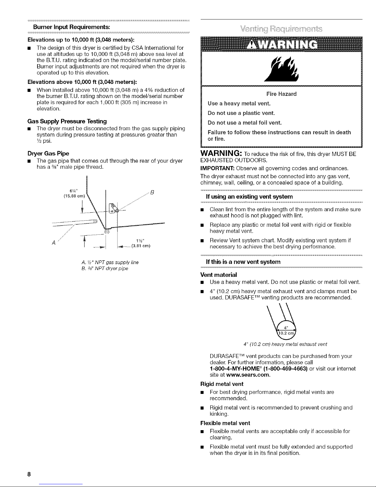
Dryer Gas Pipe
• The gas pipe that comes out through the rear of your dryer
has a %" male pipe thread.
A. _2"NPT gas supply line
B. _" NPT dryer pipe
Fire Hazard
Use a heavy metam vent.
Do not use a pmastic vent.
Do not use a metamfoil vent.
FaUure to follow these instructions can result in death
or fire.
WARNING; To reduce the risk of fire, this dryer MUST BE
EXHAUSTED OUTDOORS.
IMPORTANT: Observe all governing codes and ordinances.
The dryer exhaust must not be connected into any gas vent,
chimney, wail, ceiling, or a concealed space of a building.
If using an existing vent system
• Clean lint from the entire length of the system and make sure
exhaust hood is not plugged with lint.
• Replace any plastic or metal foil vent with rigid or flexible
heavy metal vent.
• Review Vent system chart. Modify existing vent system if
necessary to achieve the best drying performance.
If this is a new vent system
Vent material
• Use a heavy metal vent. Do not use plastic or metal foil vent.
• 4" (10.2 cm) heavy metal exhaust vent and clamps must be
used. DURASAFE TM venting products are recommended.
4" (10.2cm) heavymetal exhaust vent
DURASAFE TM vent products can be purchased from your
dealer. For further information, please call
1-800-4-MY-HOME ®(1-800-469-4663) or visit our internet
site at www.sears.com.
Rigid metal vent
• For best drying performance, rigid metal vents are
recommended.
• Rigid metal vent is recommended to prevent crushing and
kinking,
Flexible metal vent
• Flexible metal vents are acceptable only if accessible for
cleaning.
• Flexible metal vent must be fully extended and supported
when the dryer is in its final position.

• Removeexcessflexiblemetalventtoavoidsaggingand
kinkingthatmayresultinreducedairflowandpoor
performance.
• Donotinstallflexiblemetalventinenclosedwalls,ceilingsor
floors.
Elbows
45° elbows provide better airflow than 90 ° elbows.
Clamps
J/
Good Better
Use clamps to seal all joints.
Exhaust vent must not be connected or secured with screws
or other fastening devices that extend into the interior of the
duct. Do not use duct tape.
Clamp
Exhaust
Recommended hood styles are shown here.
B
(10_2cm)
A. Louvered hood style
B.Box hood style
The angled hood style (shown here) is acceptable.
(6.4 cm)
An exhaust hood should cap the vent to prevent rodents and
insects from entering the home.
Exhaust hood must be at least 12" (30.5 cm) from the ground
or any object that may be in the path of the exhaust (such as
flowers, rocks or bushes, snow line, etc.).
• Do not use an exhaust hood with a magnetic latch.
_mproper venting can cause moisture and mintto co_mect
indoors, which may resumt in:
[] Moisture damage to woodwork, furniture, paint,
wallpaper, carpets, etc=
[] Housecleaning problems and health problems.
Choose your exhaust installation type
Recommended exhaust installations
Typical installations vent the dryer from the rear of the dryer.
Other installations are possible.
B
A
A. Dryer
B. Elbow
C. Wall
D. Exhaust hood
E.Clamps
E Rigid metal or flexible metal vent
G. Vent length necessary to connect elbows
H. Exhaust outlet
Optional exhaust installations
This dryer can be converted to exhaust out the right side, left
side, or through the bottom. If you prefer, you may contact your
local dealer to have the dryer converted.
Fire Hazard
Cover unused exhaust holes with one of the following
kits:
279818 (white)
279819 (almond)
279915 (graphite}
279925 (biscuit)
Contact your Ioca_ dealer.
Failure to follow these instructions can result in death,
fire, e_ectrical shock, or serious injury.
A C
A. Standard rear offset exhaust installation
B. Left or right side exhaust installation
C. Bottom exhaust installation

Alternate installations for close clearances
Venting systems come in many varieties. Select the type best for
your installation. Two close-clearance installations are shown.
Refer to the manufacturer's instructions.
F.......
[ .......
A B
A. Over-The-Topinstallation (alsoavailablewith one
offset elbow)
B.Periscope installation
NOTE: The following kits for close clearance alternate
installations are available for purchase. For further information,
please call 1-800-4-MY-HOME ®(1-800-469-4663).
• Over-The-Top Installation:
Part Number 26-49900
• Periscope Installation (For use with dryer vent to wall vent
mismatch):
Part Number 26-49901 - Less than 5" (12.7 cm) mismatch
Part Number 26-49908 - 5" (12.7 cm) to 18" (45.72 cm)
mismatch
Part Number 26-49904 - 18" (45.72 cm) to 29" (73.66 cm)
mismatch
Part Number 26-49905 - 29" (73.66 cm) to 50" (127 cm)
mismatch
Special provisions for mobile home installations
The exhaust vent must be securely fastened to a noncombustible
portion of the mobile home structure and must not terminate
beneath the mobile home. Terminate the exhaust vent outside.
Determine vent length and elbows needed for best
drying performance
• Use the Vent system chart below to determine type of vent
material and hood combinations acceptable to use.
NOTE: Do not use vent runs longer than specified in the Vent
System Chart. Exhaust systems longer than specified will:
• Shorten the life of the dryer.
• Reduce performance, resulting in longer drying times and
increased energy usage.
The Vent system chart provides venting requirements that will
help to achieve the best drying performance.
Vent system chart
NOTE: Side and bottom exhaust installations have a 90° turn
inside the dryer. To determine maximum exhaust length, add one
90° turn to the chart.
Number of Type of Box or Angled
90° turns vent Iouvered hoods
or elbows hoods
0 Rigid metal 64 ft (20 m) 58 ft (17.7 m)
Flexible metal 36 ft (11 m) 28 ft (8.5 m)
1 Rigid metal 54 ft (16.5 m) 48 ft (14.6 m)
Flexible metal 31 ft (9.4 m) 23 ft (7 m)
2 Rigid metal 44 ft (13.4 m) 38 ft (11.6 m)
Flexible metal 27 ft (8.2 m) 19 ft (5.8 m)
3 Rigid metal 35 ft (10.7 m) 29 ft (8.8 m)
Flexible metal 25 ft (7.6 m) 17 ft (5.2 m)
4 Rigid metal 27 ft (8.2 m) 21 ft (6.4 m)
Flexible metal 23 ft (7 m) 15 ft (4.6 m)
/"
Determine vent path
• Select the route that will provide the straightest and most
direct path outdoors.
• Plan the installation to use the fewest number of elbows and
turns.
• When using elbows or making turns, allow as much room as
possible.
• Bend vent gradually to avoid kinking.
• Use the fewest 90 ° turns possible.
1. Install exhaust hood. Use caulking compound to seal exterior
wall opening around exhaust hood.
2. Connect vent to exhaust hood. Vent must fit inside exhaust
hood. Secure vent to exhaust hood with 4" (10.2 cm) clamp.
3. Run vent to dryer location. Use the straightest path possible.
See "Determine vent path." Avoid 90° turns. Use clamps to
seal all joints. Do not use duct tape, screws or other fastening
devices that extend into the interior of the vent to secure
vent.
10
Excessive Weight Hazard
Use two or more people to move and install dryer.
Failure to do so can result in back or other injury.
1. To protect the floor, use a large flat piece of cardboard from
the dryer carton. Place cardboard under the entire back edge
of the dryer.
2. Firmly grasp the body of the dryer (not the top or console
panel). Gently lay the dryer on the cardboard. See illustration.
Examine the leveling legs. Find the diamond marking.
4. Screw the legs into the leg holes by hand. Use a wrench to
finish turning the legs until the diamond marking is no longer
visible.
5. Place a carton corner post from dryer packaging under each
of the 2 dryer back corners. Stand the dryer up. Slide the
dryer on the corner posts until it is close to its final location.
Leave enough room to connect the exhaust vent.
For mobile home use
Gas dryers must be securely fastened to the floor.
Mobile home installations require a Mobile Home Installation Kit.
See "Tools and Parts" section for ordering information.
1=
2.
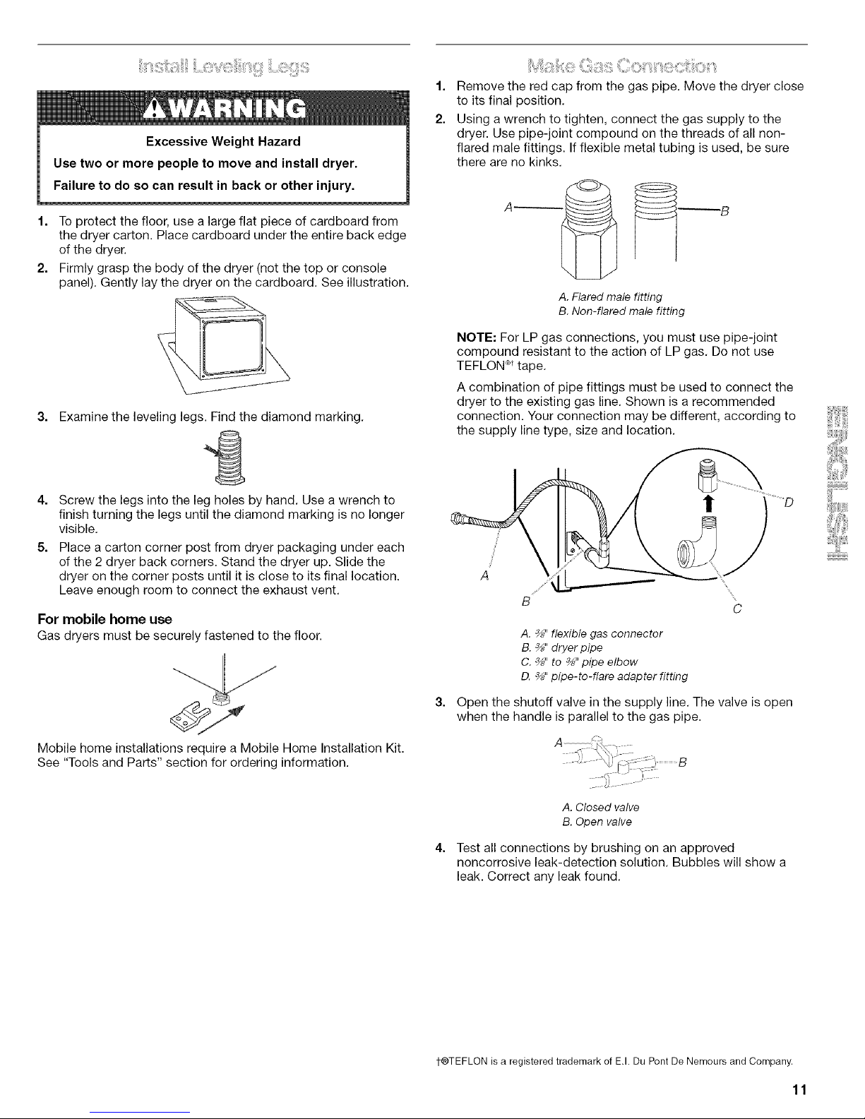
Remove the red cap from the gas pipe. Move the dryer close
to its final position.
Using a wrench to tighten, connect the gas supply to the
dryer. Use pipe-joint compound on the threads of all non-
flared male fittings. If flexible metal tubing is used, be sure
there are no kinks.
A _
A. Flared male fitting
B. Non-flared male fitting
NOTE: For LP gas connections, you must use pipe-joint
compound resistant to the action of LP gas. Do not use
TEFLON _t tape.
A combination of pipe fittings must be used to connect the
dryer to the existing gas line. Shown is a recommended
connection. Your connection may be different, according to
the supply line type, size and location.
!
J
J
A
A. %" flexible gas connector
B. %" dryer pipe
C. %" to %" pipe elbow
D. _" pipe-to-flare adapter fitting
Open the shutoff valve in the supply line. The valve is open
when the handle is parallel to the gas pipe.
A. Closed valve
B.Open valve
Test all connections by brushing on an approved
noncorrosive leak-detection solution. Bubbles will show a
leak. Correct any leak found.
t®TEFLON is a registered trademark of E.I. Du Pont De Nemours and Company.
11
1. Using a 4" (10.2 cm) clamp, connect vent to exhaust outlet in
dryer. If connecting to existing vent, make sure the vent is
clean. The dryer vent must fit over the dryer exhaust outlet
and inside the exhaust hood. Make sure the vent is secured
to exhaust hood with a 4" (10.2 cm) clamp.
2. Move dryer into its final position. Do not crush or kink vent.
Make sure dryer is level.
3. (On gas models) Check to be sure there are no kinks in the
flexible gas line.
4. Once the exhaust vent connection is made, remove the
corner posts and cardboard.
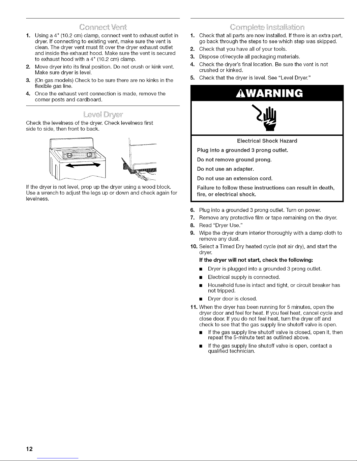
Check the levelness of the dryer. Check levelness first
side to side, then front to back.
If the dryer is not level, prop up the dryer using a wood block.
Use a wrench to adjust the legs up or down and check again for
levelness.
1. Check that all parts are now installed. If there is an extra part,
go back through the steps to see which step was skipped.
2. Check that you have all of your tools.
3. Dispose of/recycle all packaging materials.
4. Check the dryer's final location. Be sure the vent is not
crushed or kinked.
5. Check that the dryer is level. See "Level Dryer."
Emectricat Shock Hazard
Plug into a grounded 3 prong outlet.
Do not remove ground prong.
Do not use an adapter.
Do not use an extension cord.
Faimureto follow these instructions can result in death,
fire, or emectrical shock.
6. Plug into a grounded 3 prong outlet. Turn on power.
7. Remove any protective film or tape remaining on the dryer.
8. Read "Dryer Use."
9. Wipe the dryer drum interior thoroughly with a damp cloth to
remove any dust.
10. Select a Timed Dry heated cycle (not air dry), and start the
dryer.
If the dryer will not start, check the following:
• Dryer is plugged into a grounded 3 prong outlet.
• Electrical supply is connected.
• Household fuse is intact and tight, or circuit breaker has
not tripped.
• Dryer door is closed.
1f. When the dryer has been running for 5 minutes, open the
dryer door and feel for heat. If you feel heat, cancel cycle and
close door. If you do not feel heat, turn the dryer off and
check to see that the gas supply line shutoff valve is open.
• Ifthe gas supply line shutoff valve is closed, open it, then
repeat the 5-minute test as outlined above.
• Ifthe gas supply line shutoff valve is open, contact a
qualified technician.
12
DRYER USE
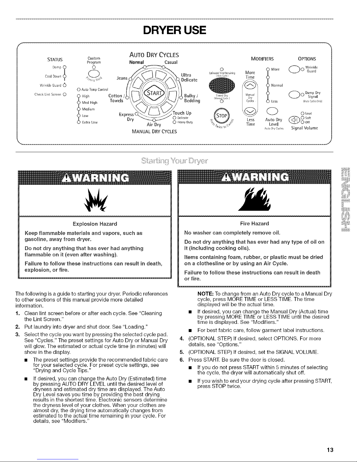
STATUS
Damp !Cool Down
Wrink[_ Guard 0
Check Lint Screen 0
AUTO DRY CYCLES
Custom MODIFIERS OPTIONS
Program NormsI CasuaB
WrinMe
0 0 0 Guard
o
Est ,qsted Trn¢ Remaining
[ AJr,, C/_l_ ]
Jean_ \ UBtra
_-_D_Delieate
Air Dry 0 HeavyDuty
MANUALDRYCYCLES
0 Auto Temp Control
Med High
Medium 0 Loud
LOW _ 0 Soft
Extra Low _._/' O Off
%ice _°c SignaU VoUume
More I More
Time
Normal
(_) Less
(2)
Less Auto Dr},
Time LeveB
AIO D!y Cycles
Explosion Hazard
Keep flammable materials and vapors, such as
gasoline, away from dryer.
Do not dry anything that has ever had anything
flammable on it (even after washing).
Failure to folmow these instructions can result in death,
explosion, or fire,
The following is a guide to starting your dryer. Periodic references
to other sections of this manual provide more detailed
information.
1. Clean lint screen before or after each cycle. See "Cleaning
the Lint Screen."
2. Put laundry into dryer and shut door. See "Loading."
3. Select the cycle you want by pressing the selected cycle pad.
See "Cycles." The preset settings for Auto Dry or Manual Dry
will glow. The estimated or actual cycle time (in minutes) will
show in the display.
• The preset settings provide the recommended fabric care
for your selected cycle. For preset cycle settings, see
"Drying and Cycle Tips."
• If desired, you can change the Auto Dry (Estimated) time
by pressing AUTO DRY LEVEL until the desired level of
dryness and estimated dry time are displayed. The Auto
Dry Level saves you time by providing the best drying
results in the shortest time. Electronic sensors determine
the dryness level of your clothes. When your clothes are
almost dry, the drying time automatically changes from
estimated to the actual time remaining in your cycle. For
details, see "Modifiers."
Fire Hazard
No washer can completely remove oil
Do not dry anything that has ever had any type of oil on
it (including cooking oils).
Items containing foam, rubber, or plastic must be dried
on a clothesline or by using an Air Cycle.
Failure to follow these instructions can result in death
or fire.
4.
5.
6.
NOTE: To change from an Auto Dry cycle to a Manual Dry
cycle, press MORE TIME or LESS TIME. The time
displayed will be the actual time.
• If desired, you can change the Manual Dry (Actual) time
by pressing MORE TIME or LESS TIME until the desired
time is displayed. See "Modifiers."
• For best fabric care, follow garment label instructions.
(OPTIONAL STEP) If desired, select OPTIONS. For more
details, see "Options."
(OPTIONAL STEP) If desired, set the SIGNAL VOLUME.
Press START. Be sure the door is closed.
• If you do not press START within 5 minutes of selecting
the cycle, the dryer will automatically shut off.
• If you wish to end your drying cycle after pressing START,
press STOP twice.
13
How Auto Moisture Sensing Plus works
EvenHeat TM improves drying performance with Auto Moisture
Sensing Plus, which advances the cycle as moisture is
extracted from clothing. A thermistor (electronic temperature
sensor) and moisture sensing strips in the dryer drum help
measure the amount of moisture in the clothes as they pass.
An electronic control determines the load type to help save
time, prevent overdrying, and increase the accuracy of the
end dryness level. After the first 5 minutes of an automatic
cycle, the estimated time display will adjust based on the
approximate load size, cycle, dryness level selected and
amount of moisture left in the clothes. When the clothes have
reached approximately 80% of the dryness level selected, the
estimated time display will adjust again, showing the final
drying time. Auto Moisture Sensing Plus takes the guesswork
out of drying time and enhances fabric care.
To stop your dryer at any time
Press STOP twice or open the door.
To pause the dryer at any time
Open the door or press STOP once.
To restart the dryer
Close the door and press START.
NOTE: Drying will continue from where the cycle was interrupted
if you close the door and press START within 5 minutes. If the
cycle is interrupted for more than 5 minutes, the dryer will shut
off. You will need to select new cycle settings before restarting
the dryer.
Properly loading your dryer can lower your utility bill and prolong
the life of your garments.
Loading suggestions
• Load the dryer by the amount of space items take up, not by
their weight.
• Do not overload the dryer. This causes uneven drying and
wrinkling.
KING SIZE TM Capacity Dryers
Heavy Work Clothes
4 jeans 2 sweatpants
4 workpants 2 sweatshirts
4 workshirts
Towels
10 bath towels
10 hand towels
14 washcloths
Mixed Load
3 sheets (1 king, 2 twin) 9 T-shirts
4 pillowcases 9 shorts
3 shirts 10 handkerchiefs
3 blouses
Select the correct cycle and temperature for your load.
The display shows the estimated cycle time when your dryer is
automatically sensing the dryness level of your load. If a cycle is
using Manual Dry, the display shows the exact number of
minutes remaining in the cycle.
Cool Down tumbles the load without heat during the last few
minutes of all cycles. Cool Down makes the loads easier to
handle. The length of the Cool Down depends on the load size
and dryness level.
Drying tips
• Follow care label directions when they are available.
• If you use fabric softener sheets, follow the package
instructions.
• Remove the load from the dryer as soon as tumbling stops to
reduce wrinkling. This is especially important for permanent
press, knits, and synthetic fabrics.
Cycle tips
• Dry most loads using the presetcycle settings.
Use this chart as a guide to dry various loads. Drying
temperature and Auto Dry Level (Normal Dry) are preset when
you choose an Auto Dry cycle. You can select a different
dryness level, depending on your load (see "Modifiers").
• For a Timed cycle, drying temperature is preset, but the time
can be adjusted.
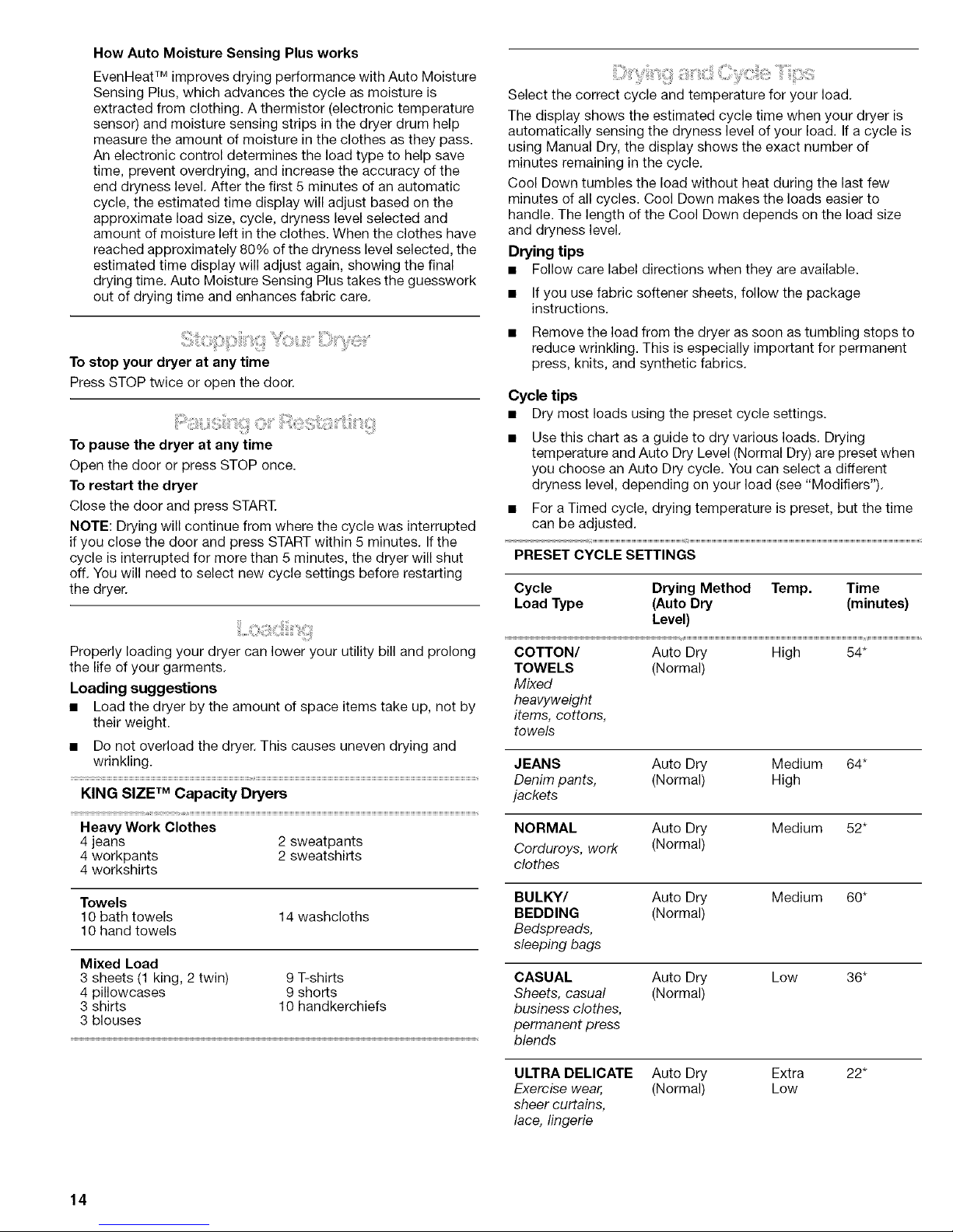
PRESET CYCLE SETTINGS
Cycle Drying Method Temp. Time
Load Type (Auto Dry (minutes)
Level)
COTTON/ Auto Dry High 54*
TOWELS (Normal)
Mixed
heavyweight
items, cottons,
towels
JEANS Auto Dry Medium 64*
Denim pants, (Normal) High
jackets
NORMAL Auto Dry
Corduroys, work (Normal)
clothes
Medium 52*
BULKY/ Auto Dry
BEDDING (Normal)
Bedspreads,
sleeping bags
Medium 60*
CASUAL Auto Dry
Sheets, casual (Normal)
business clothes,
permanent press
blends
Low 36*
ULTRA DELICATE Auto Dry
Exercise wear, (Normal)
sheer curtains,
lace, lingerie
Extra 22*
Low
14
 Loading...