

Page 1

Installation Instructions
Instrucciones de Instalación
Instructions d’Installation
English / Español / Français
Kenmore Elite
®
Front Load Washer
Lavadora a Cargo Frontal
Laveuse à Chargement Frontal
P/N 137412800 A (1012)
Sears Brands Management Corporation
Hoff man Estates, IL 60179 U.S.A.
www.kenmore.com
www.sears.com
Sears Canada Inc.
Toronto, Ontario, Canada M5B 2C3
www.sears.ca
TM
Page 2
Important Safety Instructions
WARNING
Please read all instructions before using this washer.
Recognize safety symbols, words and
labels
Safety items throughout this manual are labeled with
a WARNING or CAUTION based on the risk type as
described below:
Defi nitions
This is the safety alert symbol. It is used to alert you
to potential personal injury hazards. Obey all safety
messages that follow this symbol to avoid possible injury or
death.
DANGER
DANGER indicates an imminently hazardous situation
which, if not avoided, will result in death or serious injury.
WARNING
WARNING indicates a potentially hazardous situation
which, if not avoided, could result in death or serious
injury.
CAUTION
CAUTION indicates a potentially hazardous situation
which, if not avoided, may result in minor or moderate
injury.
Installation Checklist
Shipping Hardware
Foam shipping support (under wash tub)
removed and stored
Shipping bolts and spacers removed from rear
of appliance and stored
Hole plugs (shipped in bag in drum) installed in
holes in backsheet
Leveling
Washer is level, side-to-side and front-to-back
Cabinet is setting solid on all corners
Water Supply
HOT supply is connected to HOT inlet and
COLD supply is connected to COLD inlet
HOT and COLD water supply turned on
No leaks present at water supply connections
or appliance inlet connections recheck in 24 hours
Drain
Stand pipe or wall drain height minimum 24”
Drain hose snapped in “U” channel (shipped in
drum)
Drain hose secured in place with cable tie
(shipped in drum)
Electrical Power
House power turned on
Washer plugged in
IMPORTANT
IMPORTANT indicates installation, operation or
maintenance information which is important but not
hazard-related.
Table of Contents
Important Safety Instructions ............................................2-3
Installation Requirements ...................................................4-5
Washer Dimensions ................................................................6
Unpacking Washer .............................................................7-8
Installation Instructions ...................................................... 9-11
Reversing Door .................................................................12-14
Accessories ............................................................................ 15
Notes ...................................................................................... 16
Spanish ................................................................................... 17
Français ..................................................................................33
Final Checks
Installation Instructions
Guide
have been read thoroughly
Door locks and water enters drum when cycle
starts
2
and
Use and Care
Page 3
Important Safety Requirements
NOTE
The electrical service to the washer must conform with
local codes and ordinances and the latest edition of the
National Electrical Code, ANSI/NFPA 70, or in Canada,
the Canadian electrical code C22.1 part 1.
WARNING
SUFFOCATION HAZARD
Destroy the carton and plastic bags after the washer
is unpacked. Children might use them for play. Cartons
covered with rugs, bedspreads, or plastic sheets can
become airtight chambers causing suff ocation. Place
all materials in a garbage container or make materials
inaccessible to children.
CAUTION
EXCESSIVE WEIGHT HAZARD
To avoid back or other injury, have more than one person
move or lift the washer.
WARNING
WARNING
FIRE HAZARD
For your safety the information in this manual must be
followed to minimize the risk of fi re or explosion or to
prevent property damage, personal injury or loss of life.
Do not store or use gasoline or other fl ammable vapors
and liquids in the vicinity of this or any other appliance.
IMPORTANT
The instructions in this manual and all other literature
included with this washer are not meant to cover every
possible condition and situation that may occur. Good
safe practice and caution MUST be applied when
installing, operating and maintaining any appliance.
Maximum benefi ts and enjoyment are achieved when
all the Safety and Operating Instructions are understood
and practiced as a routine with your laundering tasks.
Save these instructions
for future reference.
FIRE HAZARD
Do not stack a dryer on top of washer already installed
on pedestal. Do not stack washer on top of dryer. Do not
stack washer on top of another washer.
Pre-Installation Requirements
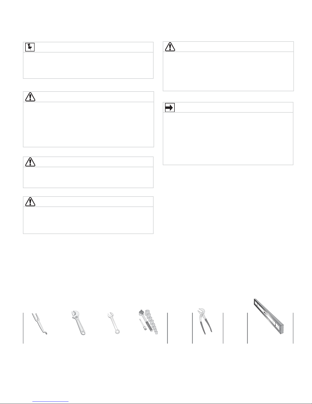
Tools and materials needed for installation:
OR OR OR AND AND
Universal wrench
supplied with
washer
Adjustable
wrench
3/8” or 10 mm
box wrench
Ratchet and
socket set
Adjustable
pliers
Carpenter’s level
3
Page 4

Grounding type
ll receptacle
wer cord with
3-prong grgr
ounded plug
Do not,
under
y cir
cumstances,
cut,
removeve,
or b
ypass the
ounding pr
ong.
Installation Requirements
Electrical system requirements
CIRCUIT - Individual, properly polarized and grounded 15
amp. branch circuit fused with 15 amp. time delay fuse
or circuit breaker.
POWER SUPPLY - 2 wire, with ground, 120 volt single
phase, 60 Hz, Alternating Current.
NOTE
Because of potentially inconsistent voltage capabilities,
the use of this washer with power created by gas
powered generators, solar powered generators, wind
powered generators or any other generator other than
the local utility company is not recommended.
OUTLET RECEPTACLE - Properly grounded 3-prong
receptacle to be located so the power supply cord is
accessible when the washer is in an installed position.
Grounding type
wawall receptacl
Do not,
under
anany cir
cumstances,
cut,
remo
or b
ypass th
grgrounding pr
ong.
2 Since your washer is equipped with a power supply
cord having an equipment-grounding conductor
and a grounding plug, the plug MUST be plugged
into an appropriate, copper wired receptacle that is
properly installed and grounded in accordance with
all local codes and ordinances or in the absence
of local codes, with the National Electrical Codes,
ANSI/NFPA 70 (latest edition). If in doubt, call
a licensed electrician. DO NOT cut off or alter
the grounding prong on the power supply cord. In
situations where a two-slot receptacle is present,
it is the owner’s responsibility to have a licensed
electrician replace it with a properly grounded three
prong grounding type receptacle.
Water supply requirements
Hot and cold water faucets MUST be installed within 42
inches (107 cm) of your washer’s water inlet. The faucets
MUST be 3/4 inch (1.9 cm) and have threading for laundry
hose connection. Water pressure MUST be between 30
and 120 psi. Pressure diff erence between hot and cold
cannot be more than 10 psi. Your water department can
advise you of your water pressure.
PoPower cord with
3-prong
ounded plug
NOTE
GFI (Ground Fault Interrupter) receptacle is not required.
Ground requirements
WARNING
ELECTRICAL SHOCK HAZARD
Improper connection of the equipment grounding
conductor can result in a risk of electrical shock. Check
with a licensed electrician if you are in doubt as to
whether the appliance is properly grounded.
1 The washer MUST be grounded. In the event of
malfunction or breakdown, grounding will reduce the
risk of electrical shock by providing a path of least
resistance for electrical current.
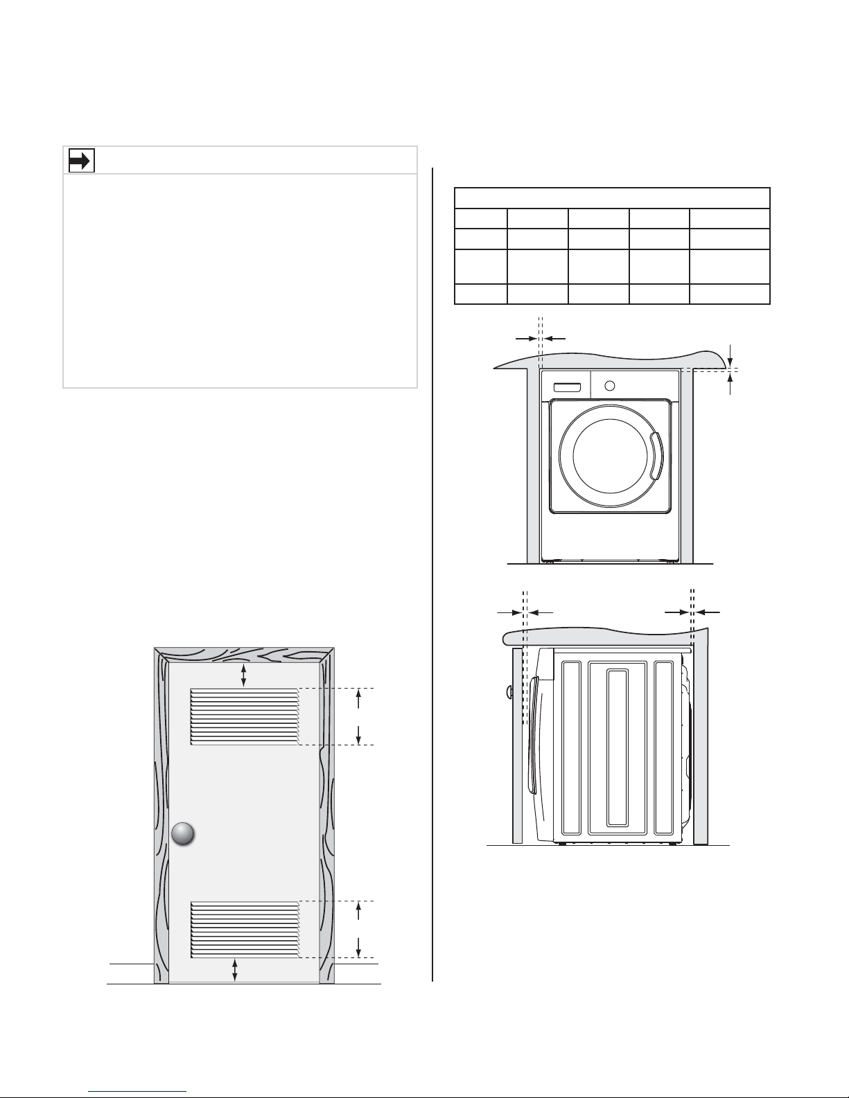
Drain system requirements
1 Drain capable of eliminating 17 gals (64.3 L) per
minute.
2 A standpipe diameter of 1-1/4 in. (3.18 cm)
minimum.
3 The standpipe height above the fl oor should be:
Minimum height: 24 in. (61 cm)
Maximum height: 96 in. (244 cm)
96”
(244cm)
max.
24”
(61cm)
min.
NOTE
Drain hose attached to the washer can reach a 74 in.
(188 cm) high standpipe. For higher standpipe, use hose
P/N 137098000, available from Sears Parts & Repair.
Call 1-800-4-MY-HOME.
4
Page 5
Clearance requirements
IMPORTANT
DO NOT INSTALL YOUR WASHER:
1 In an area exposed to dripping water or outside
weather conditions. The ambient temperature
should never be below 60° F (15.6° C) to maximize
detergent eff ectiveness.
2 In an area (garage or garage-type building)
where gasoline or other fl ammables (including
automobiles) are kept or stored.
3 On carpet. Floor MUST be solid with a maximum
slope of 1 inch (2.54 cm). To minimize vibration
or movement, reinforcement of the fl oor may be
necessary.
Installation in a Recess or Closet
If washer and dryer are installed in the same closet, door
ventilation is required: A minimum of 120 square inches
(774.2 cm²) of opening, equally divided at the top and
bottom of the door, is required. Louvered openings should
be located 3 inches (7.6 cm) from bottom and top of door.
Air openings are required to be unobstructed when a door
is installed. A louvered door with equivalent air openings
for the full length of the door is acceptable.
Installation Requirements
MINIMUM INSTALLATION CLEARANCES - Inches (cm)
SIDES REAR TOP FRONT
Alcove 0” (0 cm) 0” (0 cm)* 0” (0 cm) n/a
Under-
Counter
Closet 0” (0 cm) 0” (0 cm)* 0” (0 cm) 1” (2.5 cm)
0” (0 cm) 0” (0 cm)* 0” (0 cm) n/a
0”
(0cm)
1”
(2.5cm)
(0cm)
0”
(0cm)
0”
3”
(7.6cm)
3”
(7.6cm)
closet door
60 sq. in.
(387.1cm²)
60 sq. in.
(387.1cm²)
5
Page 6
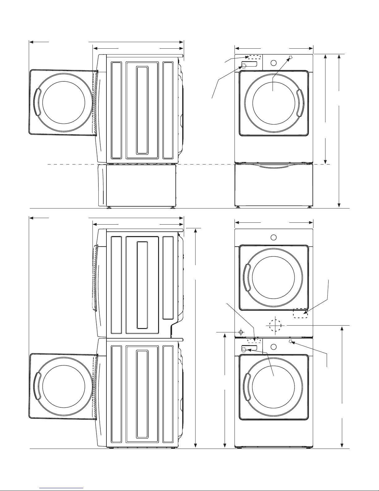
Washer Dimensions
53.5” (136 cm)
to clear open door
31.5” (79.5 cm)
to front of closed door
water supply
connection on
rear of unit
1
27.0”
(68.5 cm)
freestand
washer on fl oor
fl oor line
washer mounted on
optional pedestal
fl oor line
53.5” (136 cm)*
to clear open door
31.5” (79.5 cm)*
to front of closed door
drain hose on
rear of unit
75.75”
(192.5 cm)
power cord on
3
rear of unit
27.0”
(68.5 cm)
2
38.0”
(96.5 cm)
electrical
supply on
rear of unit
53.25”
(135.5 cm)
4
fl oor line
*Connection of water inlet hose on steam dryer adds 3/4 in. (2 cm) to installation depth.
1
Hot and cold inlet hose length on washer approximately 48.5 inches (123 cm).
2
Power supply cord length on washer approximately 60 inches (152.5 cm).
3
Drain hose length on washer approximately 59 inches (150 cm).
4
Power supply cord length on gas dryer approximately 60 inches (152.5 cm).
water supply
connection on
rear of unit
1
gas supply
pipe on rear
of gas unit
39.0”
(99 cm)
drain hose on
rear of unit
3
centerline
height for
rear vent
power cord on
rear of unit
2
(105 cm)
41.0”
6
Page 7

Removing foam packaging
WARNING
SUFFOCATION HAZARD
Destroy the carton and plastic bags after the washer
is unpacked. Children might use them for play. Cartons
covered with rugs, bedspreads, or plastic sheets can
become airtight chambers causing suff ocation. Place
all materials in a garbage container or make materials
inaccessible to children.
1 Temporarily remove door tape.
2 Open washer door and remove everything from the
drum.
3 Close door and reapply door tape.
4
Using a rug, blanket or piece of cardboard to protect
the fl oor, carefully lay the washer on its back.
Unpacking Washer
CAUTION
EXCESSIVE WEIGHT HAZARD
To avoid back or other injury, have more than one person
move or lift the washer.
5 Remove styrofoam base and shipping plug and set
them aside.
6 Carefully return the washer to an upright position.
7 Carefully move the washer to within 4 feet (1 m) of
its fi nal location.
IMPORTANT
Save styrofoam base and shipping plug for use to help
prevent washer damage during any future moves.
7
Page 8
Unpacking Washer
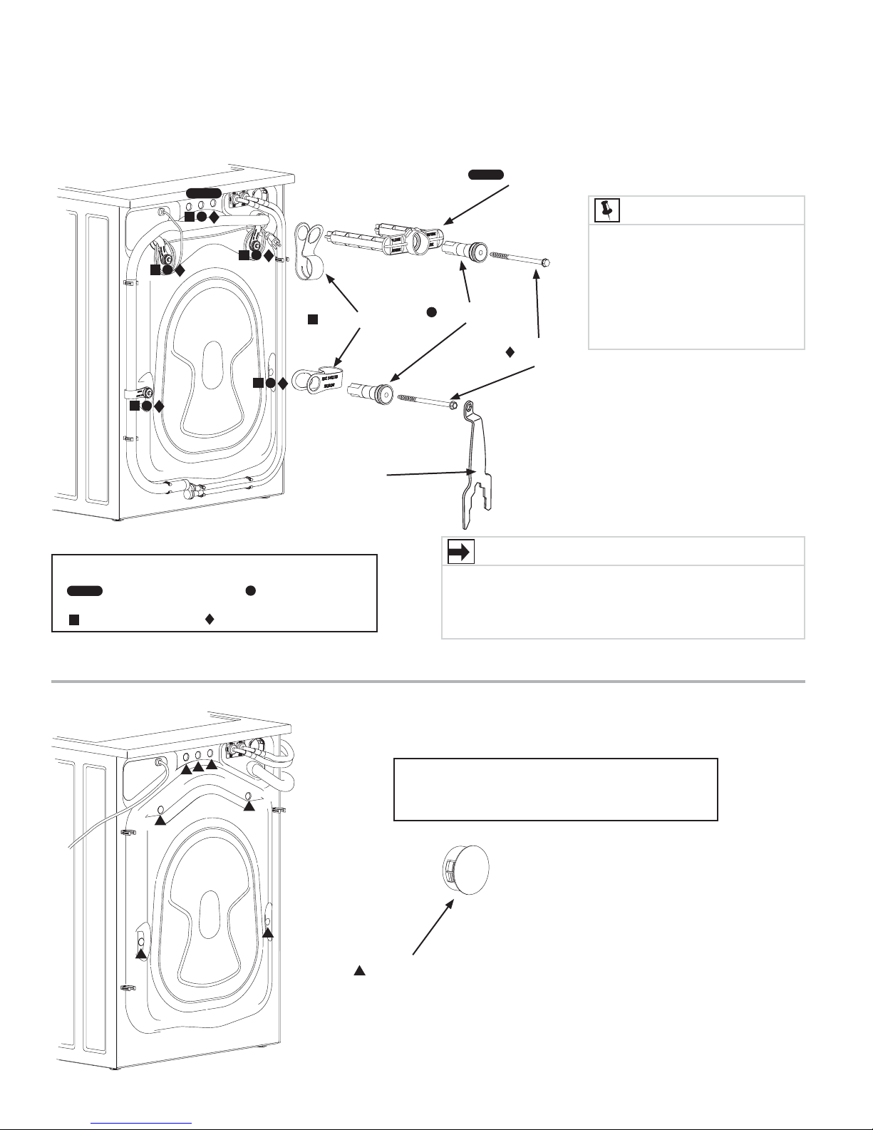
Removing shipping hardware
5 P CLAMPS
UNIVERSAL
WRENCH
(SUPPLIED)
5 SPACERS
1 SHIPPING FORK
NOTE
Rubber expansion material on
spacers may need time to relax
before they can be easily pulled
through shipping hole. You may
have to exert some force to pull
out if spacer material has not yet
fully relaxed.
5 BOLTS
Remove all of the following:
1 SHIPPING FORK
5 P CLAMPS
5 BOLTS
Installing hole plugs
5 SPACERS
IMPORTANT
Save all shipping bolts and spacers for future use. If the
washer is to be transported at a later date, the shipping
hardware must be reinstalled to help prevent shipping
damage.
Locate 7 hole plugs in the small bag supplied
with washer instruction guides. Insert them in the
holes in washer back panel.
7 HOLE PLUGS
(IN BAG)
8
Page 9

Leveling your washer
Excessive noise and vibration can be prevented by properly
leveling the washer.
1 For free standing installation and with the washer within
4 feet (1 m) of its fi nal location, place a level on top of
the washer.
2 Use adjustable pliers to adjust the leveling legs so the
washer is level front-to-rear and side-to-side, and stable
corner-to-corner.
3 Press down on alternate corners and sides and feel for
the slightest movement. Adjust the appropriate leg(s)
so the washer sits solidly on the fl oor on ALL four legs.
Keep the leveling leg extension at a minimum for best
performance of the washer.
NOTE
For pedestal installations, see additional installation
instructions included with the pedestal.
Installation Instructions
a
c
b
d
raise
lower
Connecting inlet water
1 Run some water from the hot and cold faucets to fl ush
the water lines and remove particles that might clog the
water valve screens and to determine which faucet is hot
and which is cold supply.
2 Look in the end of each water supply inlet hose and
verify that the rubber washers are in place.
RUBBER WASHERS
MUST BE PRESENT
NOTE
HOT and COLD water inlet hoses are color coded for
identifi cation. The HOT inlet hose is marked with a RED band
and the COLD inlet hose is marked with a BLUE band.
3 Connect the HOT inlet hose to the HOT water supply and
the COLD inlet hose to the COLD water supply. Tighten
by hand until snug. Then tighten each supply connection
another 2/3 turn with pliers. Do not bend, kink or pinch
water inlet hoses.
4 Turn on the water and check for leaks.
a
b
c
d
9
Page 10
Grounding type
ll receptacle
wer cord with
3-prong grgr
ounded plug
Do not,
under
y cir
cumstances,
cut,
removeve,
or b
ypass the
ounding pr
ong.
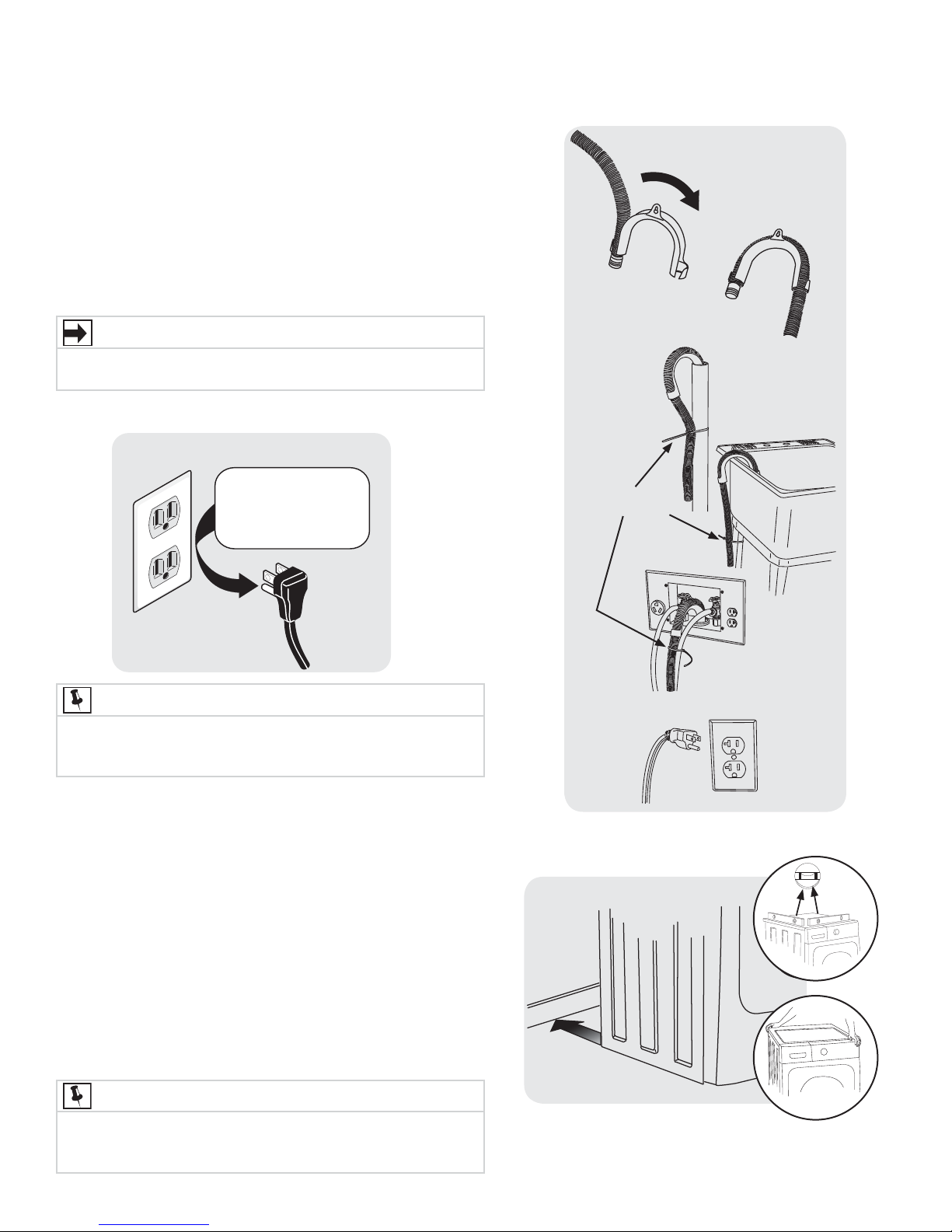
Installation Instructions
Connecting drain and electrical
1 Snap one end of the drain hose hanger (shipped in
washer drum) onto the drain hose. Continue wrapping it
around the hanger and snap it in place.
2 Place the hook end of the drain hose in the drain
opening. Secure the drain hose with the cable tie
(provided in the enclosure package) to the standpipe,
inlet hose, laundry tub, etc. so the hose does not pull out
from the force of the water.
IMPORTANT
Check to ensure the power is off at a circuit breaker/fuse
box before plugging the power cord into an outlet.
3 Plug the power cord into a grounded outlet.
Grounding type
wawall receptacl
Do not,
under
anany cir
cumstances,
cut,
remo
or b
ypass th
grgrounding pr
ong.
CABLE TIE
PoPower cord with
3-prong
ounded plug
NOTE
After you plug in the washer the fi rst time, the washer will
power up on its own. It will take approximately one minute
for the LCD to perform initial boot up procedures.
4 Turn on the power at a circuit breaker/fuse box.
5 Carefully slide the washer to its fi nal position. Recheck
for level and rock corners for stability. Remove and
discard door tape.
6 Read the
contains valuable and helpful information that will save
you time and money.
7 See the next page about performing a brief, helpful
“Installation Cycle” for your new washer.
8 If you have any questions during initial operation, please
review the “Avoid Service Checklist” in your
Guide
9 Place these instructions in a location near the washer for
future reference.
NOTE
A wiring diagram and technical data sheet are located under
the washer top panel, on top of the detergent dispenser
housing.
Use & Care Guide
before calling for service.
provided with the washer. It
Use & Care
10
Page 11

Installation Instructions - Performing Installation Cycle
With your washer in fi nal location, perform an Installation Cycle to assist in proper installation.
If your washer has this console:
2a
1
Empty washer’s drum and close door.1.
After you plug in the washer the fi rst time: wake up the washer by pressing the 2. POWER button (3), rotate cycle knob to
cycle one up from lower right position (1), and within 10 seconds, immediately and simultaneously press and hold both
the far right options button above the LED (2a) and the far right settings button under the LED (2b) for 5 seconds, or
until the LED display changes.
The LED window will display 3.
The Installation Cycle will automatically perform various diagnostic routines. At cycle completion, the LCD window may
display
an action such as
(“Call Service” - 1-800-4-MY-HOME), review the installation steps and make the necessary corrections
before you attempt to use the washer.
Your washer will exit the 4. Installation Cycle and return to normal operation the next time you wake it up.
(“Install Pass”), meaning your new washer is properly installed and ready for use. If it prompts
(“No Water”), (“Flip Hoses” - Reverse Hot and Cold Water Supply), or
(“Install”) and show estimated time of cycle completion. Press the START button (4).
2b
34
NOTE
Washer will stay awake for 3 minutes after the Installation Cycle. If you wish to immediately run the
washer through a washing cycle, press the POWER button to put the unit to sleep and then rewake it
immediately with the POWER button to continue the normal operating mode.
Please read the 5.
Use & Care Guide
and enjoy your new premium washer!
If your washer has this console:
After you plug in the washer the fi rst time, the washer will power up on its own. Then follow the prompts on the touch 1.
screen LCD, including language selection.
The 2. Installation Cycle will automatically perform various diagnostic routines. At cycle completion, the LCD window may
display INSTALL PASS!, meaning your new washer is properly installed and ready for use. If it prompts an action such as
NO WATER, CHECK HOSES or CALL SERVICE - 1-800-4-MY-HOME, review the installation steps and make the necessary corrections before you attempt to use the washer.
Your washer will exit the 3. Installation Cycle and return to normal operation the next time you wake it up.
NOTE
Washer will stay awake for 3 minutes after the Installation Cycle. If you wish to immediately run the
washer through a washing cycle, press the POWER button to put the unit to sleep and then rewake it
immediately with the POWER button to continue the normal operating mode.
Please read the 4.
Use & Care Guide
and enjoy your new premium washer!
11
Page 12
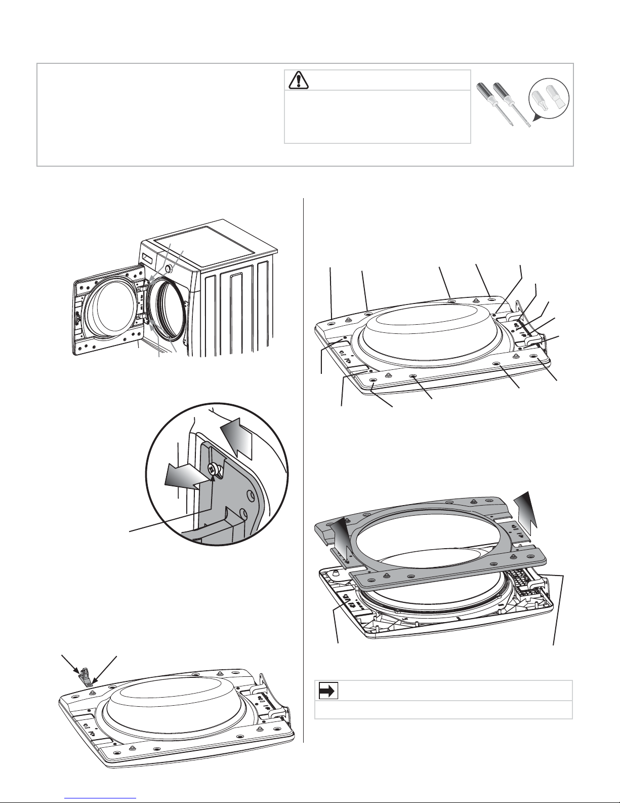
Reversing Door Swing
Be sure you have adequate swing area before 1.
reversing door.
You will need a screw driver with a #2 square and 2.
straight bit.
Protect fl at work surface, such as top of washer or 3.
fl oor near washer, with a soft cloth or towel.
Be sure washer is unplugged from power source!4.
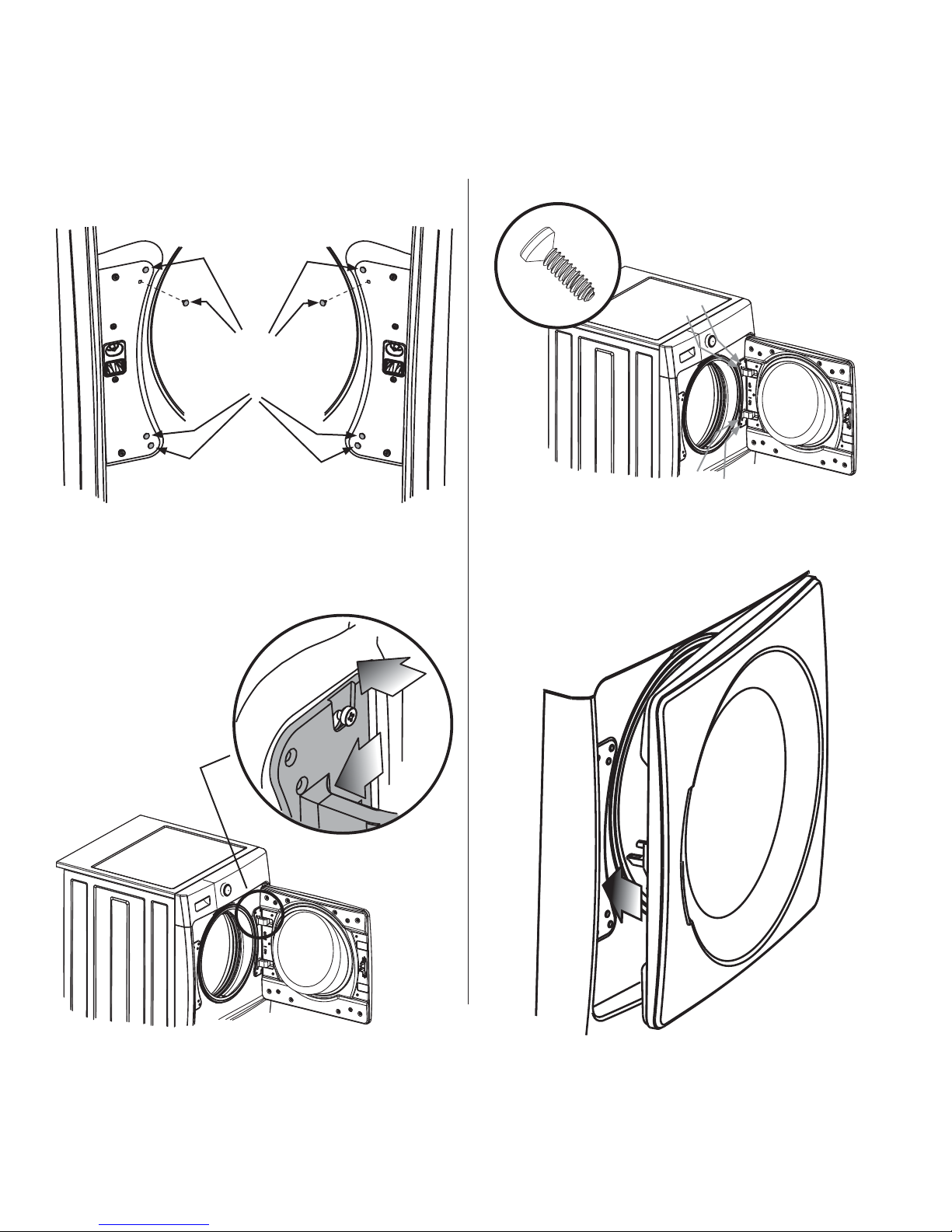
Removing the door
Open washer door and remove the 4 hinge screws.1.
1
2
3
4
Supporting door with both hands, squarely slide door 2.
and hinge outward approximately 3/8” (10 mm) so
hinge can be pulled from
shoulder bolts on front
panel.
WARNING
ELECTRICAL SHOCK HAZARD
Failure to disconnect power source
before servicing could result in personal
injury or even death.
Locate the 15 indented head screws - 8 in the small, 5.
circular recesses at top and bottom edge of the inner
door, 2 on the latch-side edge, and 5 on the hinge-side
edge. Remove and save these 15 screws.
3
12
15
1
14
2
13
Tools needed:
Screwdrivers with
#2 square &
straight bit
4
5
11
6
7
8
9
10
Do not attempt
to remove the 2
shoulder bolts.
Gently place washer door face down on fl at, covered 3.
work surface.
Remove 2 pan head screws and door strike from inner 4.
door.
12
Separate inner door assembly from outer door 6.
assembly.
STRIKE
SUPPORT
BLOCK
IMPORTANT
DO NOT remove the hinge or strike support block.
HINGE
12
Page 13
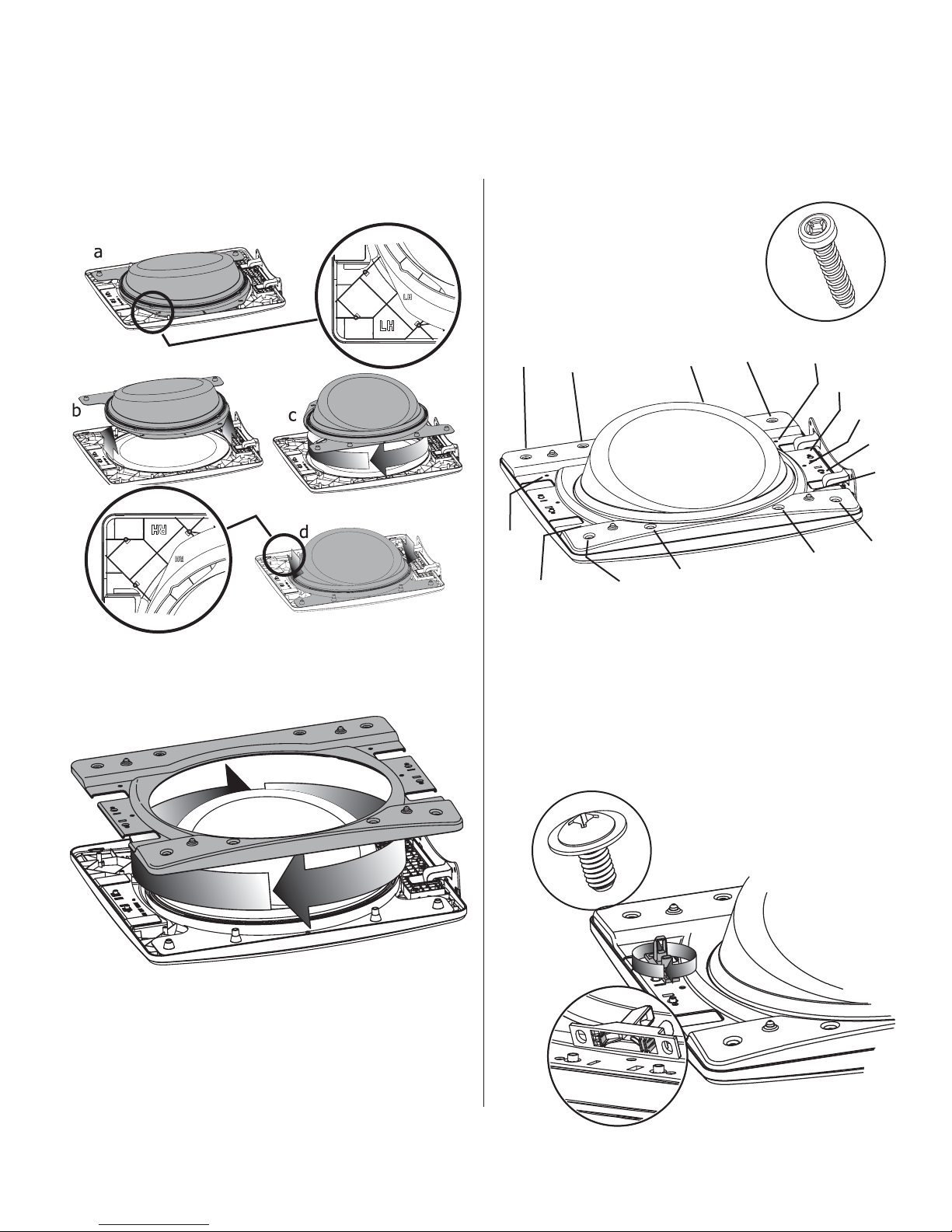
Reversing door assembly
Reversing Door Swing
Lift the inner glass and plastic ring. Rotate them 180 1.
degrees, reinstall on outer door, lining up indicators “LH” for left-hand hinge or “RH” for right-hand hinge.
Replace 15 indented head screws removed earlier. Take 3.
care not to strip out the plastic holes.
3
12
15
1
14
2
13
4
5
6
7
8
9
11
10
Rotate inner door 180 degrees and reinstall to outer 2.
door.
Rotate latch strike removed earlier 180 degrees, lining 4.
single tab to thin slot and double tab to thick slot.
Reinstall 2 pan head screws removed earlier. Take care
not to strip out the plastic holes.
13
Page 14
Reversing Door Swing
Reattaching the door
Carefully pull out the 4 small round hole plugs from the 1.
front panel and save. Move all 4 plugs to the opposite
side of the front panel and insert.
IN
MOVE
ROUND
PLUGS
Insert door and hinge assembly onto front panel 2.
shoulder bolts and slide inward to center of door
opening.
OUT
Install the 4 hinge screws removed earlier.3.
Close the door and test operation of hinge, strike and 4.
latch.
1
2
3
4
14
Page 15
Accessories
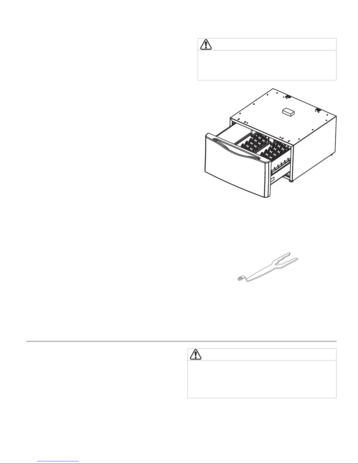
MATCHING STORAGE PEDESTAL*
White Pedestal - P/N 4175889200
Lemon Grass Pedestal - P/N 4175889100
Blackberry Pedestal - P/N 4175889000
A storage pedestal accessory, specifi cally designed for this washer
may be used to elevate the washer for ease of use. This pedestal
will add about 15.25” (39 cm) to the height of your unit for a total
height of 53.25” (135.5 cm).
*Other colors may be available. Contact the source where you
purchased your washer.
DRYER STACKING KIT
P/N 137385300
Depending on the model you purchased, a kit for stacking a
matching dryer on top of this washer may have been included in
the initial purchase of your dryer. If your model did not include a
stacking kit or you desire another stacking kit, you may order one.
DRAIN HOSE EXTENSION KIT
P/N 137098000
In order to reach standpipe heights or distances beyond the reach
of the drain hose supplied, order the DRAIN HOSE EXTENSION
KIT.
CAUTION
Failure to use accessories manufactured by (or
approved by) the manufacturer could result in
personal injury, property damage or damage to the
washer.
MOBILE HOME INSTALLATION KIT
P/N 137067200
Installation in a mobile home requires the use of a MOBILE HOME
INSTALLATION KIT.
UNIVERSAL APPLIANCE WRENCH
P/N 137019200
A UNIVERSAL APPLIANCE WRENCH is available to aid in dryer/
washer/pedestal feet adjustment.
TOUCH UP PAINT PENS*
White Touch Up Pen - P/N 5304468812
Lemon Grass Touch Up Pen - P/N 5304481253
Blackberry Touch Up Pen - P/N 5304481254
*Other colors may be available. Contact the source where you
purchased your washer.
Replacement parts:
If replacements parts are needed for your washer, contact
the source where you purchased your washer or refer to
your
Use and Care Guide
for more information.
Label all wires prior to disconnection when servicing
controls. Wiring errors can cause improper and
dangerous operation. Verify proper operation after
servicing.
WARNING
ELECTRICAL SHOCK HAZARD
15
Page 16

Notes
16
Page 17

Installation Instructions
Instrucciones de Instalación
Instructions d’Installation
English / Español / Français
Kenmore Elite
®
Front Load Washer
Lavadora a Cargo Frontal
Laveuse à Chargement Frontal
Sears Brands Management Corporation
Hoff man Estates, IL 60179 U.S.A.
www.kenmore.com
www.sears.com
Sears Canada Inc.
Toronto, Ontario, Canada M5B 2C3
www.sears.ca
TM
Page 18

Instrucciones Importantes de Seguridad
ADVERTENCIA
Lea todas las instrucciones antes de usar este secadora.
Identifi cación de los símbolos, palabras
y avisos de seguridad
Las indicaciones de seguridad incluidas en este manual
aparecen precedidas de un aviso titulado “ADVERTENCIA”
o “PRECAUCIÓN”, de acuerdo con el nivel de riesgo.
Defi niciones
Este es el símbolo de alerta de seguridad. Se usa para
alertar sobre peligros potenciales de lesiones personales.
Obedezca todos los mensajes de seguridad que tengan este
símbolo para evitar posibles lesiones personales o la muerte.
PELIGRO
PELIGRO indica una situación de peligro inminente que,
si no se evita, podría causar lesiones graves o la muerte.
ADVERTENCIA
ADVERTENCIA indica una situación potencialmente
peligrosa que, si no se evita, podría causar lesiones
personales graves o la muerte.
Lista de Verifi cación
de Instalación
Ferretería de envío y transporte
Se retiró y guardó el soporte de espuma de
empaque (debajo de la tina de lavado)
Se retiraron y guardaron los pernos y
espaciadores de la parte trasera del
electrodoméstico
Se instalaron los tapones (empacados en una
bolsa en el interior del tambor) en los agujeros de
la lámina trasera
Nivelación
La lavadora está nivelada de lado a lado y de
adelante hacia atrás
La lavadora descansa fi rmemente sobre sus
cuatro esquinas
Suministro de agua
Se conectó el suministro de agua CALIENTE a la
admisión de agua CALIENTE y el suministro de
agua FRÍA a la admisión de agua FRÍA
Se abrió el suministro de agua CALIENTE y FRÍA
No hay escapes en las conexiones del suministro
de agua o en las conexiones de admisión del
electrodoméstico vuelva a verifi car a las 24 horas
PRECAUCIÓN
PRECAUCIÓN indica una situación potencialmente
peligrosa que, si no se evita, podría causar lesiones
personales leves o moderadas.
IMPORTANTE
IMPORTANTE indica información de instalación,
funcionamiento o mantenimiento que es importante,
pero que no está relacionada con la seguridad.
ÍNDICE
Instrucciones Importantes de Seguridad ...................... 18-19
Requisitos de Instalación ............................................... 20-21
Dimensiones de la Lavadora...............................................22
Desembalaje de la Lavadora ...................................... 23-24
Instrucciones de Instalación ......................................... 25-27
Inversión de la Puerta ................................................... 28-30
Accesorios .............................................................................. 31
Notas ......................................................................................32
Drenaje
Tubo vertical o drenaje de pared a una altura
mínima de 24” (61 cm)
Manguera de drenaje enganchada en el canal en
“U” (empacado en el tambor)
Manguera de drenaje fi jada en su lugar con un
amarre para cables (empacado en el tambor)
Suministro eléctrico
El suministro eléctrico del hogar está
La lavadora está conectada
Inspección fi nal
Lea bien las
Guía de Uso y Cuidado
La puerta se bloquea y el agua entra al tambor
cuando se inicia el ciclo
Instrucciones de Instalación
y la
18
Page 19

Instrucciones Importantes de Seguridad
NOTA
La reparación eléctrica de la lavadora debe
cumplimentar los códigos y las ordenanzas locales y la
última edición del Código Eléctrico Nacional (National
Electrical Code), el ANSI/NFPA 70, o bien en Canadá,
el CSA C22.1 del Código Eléctrico de Canadá (Canadian
Electrical Code) Parte 1.
ADVERTENCIA
PELIGRO DE ASFIXIA
Después de desembalar la lavadora, destruya los
cartones y las bolsas de plástico. Los niños podrían
utilizarlos para jugar. Los cartones cubiertos con
alfombras, cubrecamas, o láminas de plástico pueden
convertirse en cámaras de aire herméticamente cerradas
y provocar asfi xia. Coloque todos los materiales en un
basurero o manténgalos fuera del alcance de los niños.
PRECAUCIÓN
PELIGRO DE EXCESO DE PESO
Para evitar lesiones en la espalda u otro tipo de lesiones,
procure levantar o mover la lavadora con la ayuda de
más de una persona.
ADVERTENCIA
ADVERTENCIA
PELIGRO DE INCENDIO
Para su seguridad, debe seguir la información de esta
guía para minimizar el riesgo de incendio o explosión o
para evitar daños a la propiedad, lesiones personales
o incluso la muerte. No almacene ni utilice gasolina ni
otros líquidos o vapores infl amables cerca de este o de
cualquier otro electrodoméstico.
IMPORTANTE
Las instrucciones de esta guía y todo el material que
se incluye con esta lavadora no tienen como propósito
cubrir todas las condiciones y situaciones que puedan
presentarse. Cuando instale, opere o repare cualquier
artefacto DEBE tener cuidado y hacer uso de buenas
prácticas de seguridad.
Se obtienen mayores benefi cios y se disfruta más del
artefacto cuando se comprenden y se practican de
manera rutinaria todas las Instrucciones de Seguridad y
Funcionamiento al realizar las tareas de lavado.
Conserve estas instrucciones
para referencia futura.
PELIGRO DE INCENDIO
No apile la secadora sobre la lavadora si ya está
instalada sobre un pedestal. No apile la lavadora sobre
la secadora. No apile la lavadora sobre otra lavadora.
Requisitos de preinstalación
Herramientas y materiales necesarios para la instalación:
OO Y Y
Llave
ajustable
Llave de cubo
de 3/8" o 10 mm
Juego de
manguito
y trinquete
Pinzas
ajustables
Nivel de carpintero
19
Page 20

Requisitos de Instalación
Tom
acorriente con
puesta a tierra
ninguna circunstancia.
No corte, retire ni
deshabilite la clavija de
conexión a tierra bajo
Cordón eléctrico de 3 clavijas
con puesta a tierra
Requisitos del sistema eléctrico
CIRCUITO - Circuito individual de bifurcación de 15 amp.,
correctamente polarizado y con conexión a tierra
con fusible de retardo de 15 amp. o con interruptor
automático.
SUMINISTRO ELÉCTRICO: corriente alterna de 2 cables,
con conexión a tierra, 120 voltios, monofásica, 60 Hz.
NOTA
Debido a posibles variaciones en el voltaje, no se
recomienda utilizar esta lavadora con electricidad
generada a partir de generadores a gas, solares, eólicos
ni de ninguna otra clase que no sean los empleados por
su empresa de electricidad local.
RECEPTÁCULO DEL TOMACORRIENTE - Receptáculo para
enchufes de 3 patas con conexión a tierra que debe
estar ubicado en un lugar que sea accesible para el
cable de alimentación eléctrica cuando la lavadora se
encuentre instalada.
Tom
acorriente con
puesta a tierr
No corte, retire ni
deshabilite la clavija de
conexión a tierra bajo
ninguna circunstancia.
Cordón eléctrico de 3 clavijas
con puesta a tierra
NOTA
No es necesario conectar un tomacorriente con GFI
(interruptor de falla de conexión a tierra).
estar conectado a un receptáculo adecuado con
cable de cobre correctamente instalado y con
conexión a tierra, de acuerdo con todos los códigos
y las ordenanzas locales o, ante la ausencia de
ordenanzas locales, con el Código Eléctrico Nacional
(National Electrical Codes), ANSI/NFPA 70 (última
edición). Ante cualquier duda, comuníquese con un
electricista autorizado. NO corte ni dañe la espiga
de conexión a tierra del cable de alimentación
eléctrica. En los casos en los que se dispone de un
receptáculo de dos ranuras, es responsabilidad del
usuario pedir a un electricista autorizado que lo
cambie por un receptáculo para enchufes de tres
patas con una adecuada conexión a tierra.
Requisitos de la entrada de agua
Los grifos de agua caliente y fría DEBEN instalarse a
una distancia no mayor de 107 cm (42 pulgadas) de la
entrada de agua de la lavadora. Los grifos DEBEN estar a
1,9 cm (3/4 pulgadas) con roscas para la conexión de la
manguera de lavado. La presión de agua DEBE ser de 30
a 120 psi. La diferencia de presión entre el agua caliente y
fría no debe superar los 10 psi. El departamento hidráulico
puede asesorarlo con respecto a la presión de agua con la
que usted cuenta.
Requisitos del sistema de desagüe
1 Desagüe con capacidad para eliminar 64,3 l (17
galones) por minuto.
2 Un tubo vertical con un diámetro mínimo de 3,18 cm
(1-1/4 pulg.).
3 La altura del tubo vertical por encima del suelo
debe ser:
Altura mínima: 61 cm (24 pulgadas)
Altura máxima: 244 cm (96 pulgadas)
Requisitos de conexión a tierra
ADVERTENCIA
PELIGRO DE DESCARGA ELÉCTRICA
Una conexión incorrecta del conductor de conexión
a tierra del equipo puede provocar un peligro de
descarga eléctrica. Si no está seguro de haber realizado
correctamente la conexión a tierra del artefacto,
consulte a un electricista autorizado.
1 La lavadora DEBE tener conexión a tierra. En el caso
2
de que la lavadora no funcione correctamente o se
descomponga, la conexión a tierra reduce el riesgo
de descarga eléctrica porque ofrece una trayectoria
de menor resistencia para la corriente eléctrica.
Debido a que la lavadora está equipada con un
cable de alimentación eléctrica que cuenta con un
conductor de conexión a tierra, el enchufe DEBE
96”
(244cm)
max.
24”
(61cm)
min.
NOTA
La manguera de drenaje conectada a la lavadora
puede alcanzar un tubo vertical de hasta 188 cm (74
pulgadas) de altura. Si el tubo vertical es más alto, debe
utilizar una manguera P/N 137098000, disponible en
Sears Parts & Repair. Llame al +1 8004MYHOME (+1
8004694663).
20
Page 21

Requisitos de despeje
Requisitos de Instalación
IMPORTANTE
NO INSTALE LA LAVADORA:
1 En una zona expuesta a la humedad o a las
condiciones climáticas externas. Para maximizar la
efi cacia del detergente, la temperatura ambiente
nunca debe ser menor a los 15,6° C (60° F).
2 En un área (garaje o construcción tipo garaje)
en la cual haya o se almacene gasolina u otros
productos infl amables (incluso automóviles).
3 Sobre una alfombra. El piso DEBE ser fi rme con
una pendiente máxima de 2,54 cm (1 pulgada).
Para reducir vibraciones o movimientos, puede que
sea necesario reforzar el piso.
Instalación en un Nicho o Armario
Si la lavadora y la secadora se instalan en el mismo
armario, será necesaria la ventilación en la puerta de este:
Se necesita un mínimo de 774,2 cm² (120 pulgadas²) de
abertura, dividido en partes iguales en la parte superior e
inferior de la puerta. Las aberturas de ventilación deben
estar ubicadas a 7,6 cm (3 pulgadas) de la parte superior
e inferior de la puerta. Es necesario que las aberturas de
aire no estén obstruidas cuando se instala una puerta. Se
acepta una puerta que tenga aberturas de ventilación
distribuidas uniformemente en toda la superfi cie.
MINIMUM INSTALLATION CLEARANCES - Inches (cm)
SIDES REAR TOP FRONT
Hueco 0” (0 cm) 0” (0 cm)* 0” (0 cm) n/d
Debajo
de la
0” (0 cm) 0” (0 cm)* 0” (0 cm) n/d
encimera
Armario 0” (0 cm) 0” (0 cm)* 0” (0 cm) 1” (2.5 cm)
0”
(0cm)
0”
(0cm)
1”
(2.5cm)
0”
(0cm)
3”
(7.6cm)
3”
(7.6cm)
puerta del armario
60 sq. in.
(387.1cm²)
60 sq. in.
(387.1cm²)
21
Page 22

Dimensiones de la Lavadora
53.5” (136 cm)
para destapar abra la puerta
31.5” (79.5 cm)
al frente de la puerta cerrada
conexión del
suministro de
agua en la
parte trasera de
la lavadora
1
27.0”
(68.5 cm)
lavadora independiente
sobre el piso
línea del piso
lavadora colocada sobre
pedestal opcional
línea del piso
53.5” (136 cm)*
para destapar abra la puerta
31.5” (79.5 cm)*
al frente de la puerta cerrada
manguera de drenaje
en la parte trasera de
la lavadora
75.75”
(192.5 cm)
3
conexión del
suministro de
agua en la
parte trasera de
la lavadora
suministro
eléctrico en la
parte trasera
de la unidad
1
27.0”
(68.5 cm)
2
53.25”
(135.5 cm)
38.0”
(96.5 cm)
suministro eléctrico
en la parte trasera
de la unidad
4
1
La longitud de la manguera de admisión de agua caliente y fría de la lavadora es de aproximadamente 123 cm (48,5 in).
2
La longitud del cable de alimentación de la lavadora es de aproximadamente 152,5 cm (60 in).
3
La longitud de la manguera de drenaje de la lavadora es de aproximadamente 150 cm (59 in).
4
La longitud del cable de alimentación de la secadora a gas es de aproximadamente 152,5 cm (60 in).
línea del piso
22
tubería de
suministro de gas en
la parte trasera de
la unidad de gas
39.0”
(99 cm)
manguera de drenaje
en la parte trasera de
la lavadora
3
altura de la línea
central para
ventilación trasera
suministro
eléctrico en la
parte trasera
de la unidad
(105 cm)
2
41.0”
Page 23

Retiro de la espuma de embalaje
ADVERTENCIA
PELIGRO DE ASFIXIA
Después de desembalar la lavadora, destruya los
cartones y las bolsas de plástico. Los niños podrían
utilizarlos para jugar. Los cartones cubiertos con
alfombras, cubrecamas, o láminas de plástico pueden
convertirse en cámaras de aire herméticamente cerradas
y provocar asfi xia. Coloque todos los materiales en un
basurero o manténgalos fuera del alcance de los niños.
1 Retire la cinta de la puerta momentáneamente.
2 Abra la puerta de la lavadora y retire todo lo que
haya en el tambor.
3 Cierre la puerta y vuelva a colocar la cinta sobre
esta.
4
Utilizando una alfombra, frazada o trozo de
cartón para proteger el piso, recueste la lavadora
cuidadosamente sobre su parte trasera.
Desembalaje de la Lavadora
PRECAUCIÓN
PELIGRO DE EXCESO DE PESO
Para evitar lesiones en la espalda u otro tipo de lesiones,
procure levantar o mover la lavadora con la ayuda de
más de una persona.
5 Retire la espuma de poliestireno y el tapón de
embalaje, y déjelos a un lado.
6 Vuelva a colocar la lavadora en posición vertical
cuidadosamente.
7 Traslade la lavadora con cuidado a fi n de colocarla
a aproximadamente 1 m (4 pies) de la ubicación
fi nal.
IMPORTANTE
Guarde la espuma de poliestireno y el tapón de embalaje
para utilizarlos para evitar daños a la lavadora en futuros
traslados.
23
Page 24

Desembalaje de la Lavadora
Retiro del embalaje de protección
5 P ABRAZADERAS “P”
LLAVE
UNIVERSAL
(INCLUIDA)
1 HORQUILLA PARA TRANSPORTE
5 ESPACIADORES
5 PERNOS
NOTA
Es posible que el material de goma
en los espaciadores necesite tiempo
para suavizarse antes de poder
tirar de él a través de los agujeros
del empaque. Es posible que tenga
que ejercer fuerza para retirar el
material espaciador si éste no se ha
suavizado aún.
Retire lo siguiente:
1 HORQUILLA PARA TRANSPORTE
5 ESPACIADORES 5 ABRAZADERAS “P”
5 PERNOS
Instalación de los tapones para agujeros
Ubique los 7 tapones para agujeros en la pequeña
bolsa que viene con las guías de instrucciones de
la lavadora. Insértelos en los agujeros del panel
trasero de la lavadora.
7 TAPONES PARA AGUJEROS
(EN BOLSA)
IMPORTANTE
Guarde todos los pernos y espaciadores de embalaje para su
uso posterior. Si se va a transportar la lavadora más adelante,
deberá colocar el embalaje de protección nuevamente para
evitar que se produzcan daños durante el traslado.
24
Page 25

Nivelación de la lavadora
Las vibraciones y el ruido excesivo se pueden evitar nivelando
la lavadora correctamente.
1
Para una instalación independiente de la unidad, con la
lavadora a aproximadamente 1 m (4 pies) de la ubicación
fi nal, coloque un nivel en la parte superior de esta.
2 Utilice la pinzas ajustables para ajustar las patas
niveladoras de modo que la lavadora esté nivelada en
relación con todos sus lados, atrás/adelante y derecha/
izquierda, y estabilizada en las cuatro esquinas.
3 Presione hacia abajo las distintas esquinas y lados para
asegurarse de que no haya vibración alguna. Ajuste
las patas correspondientes de modo que la lavadora
descanse fi rmemente en el piso sobre las CUATRO patas.
Mantenga la extensión de las patas niveladoras al
mínimo para un mejor rendimiento de la lavadora.
NOTA
Para instalar un pedestal, consulte las instrucciones de
instalación adicionales que vienen con dicho producto.
Instrucciones de Instalación
a
c
b
levantar
d
bajar
Conexión del suministro de agua de entrada
Haga correr un poco de agua de los grifos de agua
1
caliente y fría para enjuagar los caños de agua y
eliminar las partículas que puedan obstruir los fi ltros de la
llave de paso y para determinar cuál canilla corresponde
al suministro de agua caliente y cuál al de agua fría.
2 Examine el extremo de cada manguera de entrada
de agua y verifi que que las arandelas de goma se
encuentran en su lugar.
ARANDELAS DE GOMA
DEBEN ESTAR PRESENTES
NOTA
Las mangueras de entrada de agua CALIENTE y FRÍA están
codifi cadas por colores para su identifi cación. La manguera
de entrada de agua CALIENTE está marcada con una cinta
ROJA y la de agua FRÍA, con una AZUL.
a
b
c
d
3 Conecte la manguera de entrada de agua CALIENTE al
suministro de agua CALIENTE y la manguera de entrada
de agua FRÍA al suministro de agua FRÍA. Ajústelas
con la mano hasta que queden fi rmes. Ajuste ambas
conexiones de suministro de agua 2/3 más de vuelta con
la pinza. No doble, tuerza o presione las mangueras de
admisión de agua.
4 Abra el grifo y verifi que que no haya fugas.
25
Page 26

Instrucciones de Instalación
Tom
acorriente con
puesta a tierra
ninguna circunstancia.
No corte, retire ni
deshabilite la clavija de
conexión a tierra bajo
Cordón eléctrico de 3 clavijas
con puesta a tierra
Conexión del desagüe y del suministro eléctrico
1 Enganche un extremo del gancho de la manguera de
drenaje (empacada en el tambor de la lavadora) en la
manguera de drenaje. Continúe deslizando la manguera
alrededor del soporte y encájela en su lugar.
2 Coloque el extremo con gancho de la manguera de drenaje
en la abertura de desagüe. Fije la manguera de drenaje con
el amarre para cables (que viene en la caja) al tubo vertical,
la manguera de entrada, la tina del lavadero, etc. para que
no se salga por la fuerza del agua.
IMPORTANTE
Revise la caja del interruptor automático/fusibles para
asegurarse de que la electricidad esté desconectada antes de
conectar el cable de alimentación al tomacorriente.
3 Conecte el cable de alimentación a un tomacorriente con
conexión a tierra.
Tom
acorriente con
puesta a tierr
No corte, retire ni
deshabilite la clavija de
conexión a tierra bajo
ninguna circunstancia.
AMARRE
PARA
CABLES
Cordón eléctrico de 3 clavijas
con puesta a tierra
NOTA
Después de conectarla por primera vez, la lavadora se
encenderá sola. La pantalla LCD tomará aproximadamente un
minuto en realizar los procedimientos de encendido inicial.
4 Conecte la electricidad desde la caja del interruptor
automático/fusibles.
5 Deslice la lavadora a su posición fi nal cuidadosamente.
Vuelva a verifi car que la lavadora esté nivelada y
estabilizada. Retire y deseche la cinta de la puerta.
6 Consulte la
la lavadora. Dicha guía contiene información útil y valiosa
que le ahorrará tiempo y dinero.
7 Consulte las instrucciones de la siguiente página para ejecutar
un “ciclo de instalación” breve y útil en su nueva lavadora.
8 Si tiene alguna pregunta durante el funcionamiento inicial,
repase la “Lista de control para evitar el servicio técnico” de
su
Guía de Uso y Cuidado
9 Coloque estas instrucciones cerca de la lavadora para
referencia futura.
NOTA
Debajo del panel superior de la lavadora, sobre el
compartimiento para distribución del detergente, encontrará una
hoja de información técnica y un diagrama de cableado.
Guía de Uso y Cuidado
antes de llamar al servicio técnico.
que se proporciona con
26
Page 27

Instrucciones de Instalación - Ejecución del ciclo de instalación
Una vez que la lavadora se encuentre en la ubicación defi nitiva, realice un ciclo de instalación para facilitar la instalación
adecuada.
2a
Si su lavadora tiene esta consola:
1
Vacíe el tambor de la lavadora.1.
Después de enchufar la lavadora por primera vez: presione el botón “2. POWER” (alimentación) [3] para encender la lava-
dora, gire la perilla de selección de ciclos hasta el primer ciclo desde la posición inferior derecha (1) y, dentro de los 10
segundos, inmediata y simultáneamente, oprima y mantenga oprimido el botón de opciones ubicado en el extremo derecho, arriba de la pantalla (2a), y el botón de ajustes ubicado en el extremo derecho, debajo de la pantalla (2b), durante
5 segundos o hasta que la pantalla cambie.
La pantalla LED mostrará 3. (“Install” - Instalar) y el tiempo estimado de duración del ciclo. Presione el botón
“START” (encender). El ciclo de instalación realizará varias rutinas de diagnóstico. Cuando termine el ciclo, la pantalla
de LCD mostrará (“Install Pass” - Instalación Aprobada), lo que signifi ca que su nueva lavadora está
correctamente instalada y lista para ser usada. If it prompts an action such as
Agua), (“Flip Hoses” - Invierta el suministro de agua caliente y fría), or
- Solicite Servicio al 800-469-4663), repase los pasos de instalación y realice las modifi caciones necesarias antes de
intentar hacer funcionar la lavadora.
La lavadora saldrá del ciclo de instalación y regresará al funcionamiento normal la próxima vez que la encienda.4.
(“No Water” - No Hay
2b
34
(“Call Service”
NOTA
La lavadora permanecerá encendida durante 3 minutos tras la ejecución del ciclo de instalación. Si desea ejecutar un
ciclo de lavado inmediatamente después de fi nalizado dicho ciclo, presione el botón “POWER” (alimentación) para
activar el modo suspendido y encienda la unidad enseguida para continuar con el modo de funcionamiento normal.
Consulte la 5.
Guía de Uso y Cuidado
y disfrute de su nueva lavadora de alta calidad.
Si su lavadora tiene esta consola:
Después de conectarla por primera vez, la lavadora se encenderá sola. Luego siga las instrucciones de la pantalla LCD 1.
táctil, incluyendo la selección del idioma.
El ciclo de instalación realizará varias rutinas de diagnóstico. Cuando termine el ciclo, la interfaz de usuario de la pan-2.
talla LCD mostrará INSTALACIÓN APROBADA, lo que signifi ca que su nueva lavadora está correctamente instalada y
lista para ser usada. Si la pantalla solicita una acción como NO HAY AGUA, INVIERTA LAS MANGUERAS o SOLICITE
SERVICIO al 1-800-469-4663, repase los pasos de instalación y realice las modifi caciones necesarias antes de intentar
hacer funcionar la lavadora.
La lavadora saldrá del ciclo de instalación y regresará al funcionamiento normal la próxima vez que la encienda.3.
NOTA
La lavadora permanecerá encendida durante 3 minutos tras la ejecución del ciclo de instalación. Si desea ejecutar un
ciclo de lavado inmediatamente después de fi nalizado dicho ciclo, presione el botón “POWER” (alimentación) para
activar el modo suspendido y encienda la unidad enseguida para continuar con el modo de funcionamiento normal.
Consulte la 4.
Guía de Uso y Cuidado
y disfrute de su nueva lavadora de alta calidad.
27
Page 28

Inversión de la Puerta
Asegúrese de que haya sufi ciente espacio de giro 1.
antes de invertir la puerta.
Necesitará un destornillador con punta cuadrada 2.
n.º 2.
Proteja las superfi cies de trabajo planas, como la 3.
parte superior de la lavadora o el piso cerca de
ésta utilizando un paño o toalla suave.
¡Asegúrese de que la lavadora esté desenchufada 4.
del suministro eléctrico!
Retiro de la puerta
Abra la puerta de la lavadora y retire los 4 tornillos de 1.
la bisagra.
1
2
3
4
Mientras sostiene la puerta con ambas manos, deslice 2.
la puerta y la bisagra hacia afuera, aproximadamente
10 mm (3/8”), de manera que
la bisagra se pueda retirar
de los pernos del panel
delantero.
ADVERTENCIA
PELIGRO DE DESCARGA ELÉCTRICA
El no desconectar el suministro eléctrico
antes de realizar cualquier reparación
puede ocasionar lesiones personales o
incluso la muerte.
Ubique los 15 tornillos de cabeza corrugada: 8 en las 5.
cavidades pequeñas y circulares en el borde superior e
inferior de la puerta interna, 2 en el borde del lado del
gancho y 5 en el borde del lado de la bisagra. Retire y
guarde estos 15 tornillos.
3
12
15
1
14
2
13
Herramientas
necesarias:
Destornilladores
con punta recta
y plana #2
4
5
6
7
8
9
11
10
No intente retirar
los 2 pernos.
Coloque cuidadosamente la puerta de la lavadora hacia 3.
abajo sobre una superfi cie de trabajo plana y protegida.
Retire los 2 tornillos de cabeza plana y la cerradura de 4.
la puerta interior.
12
Separe el conjunto de la puerta interior del conjunto de 6.
la puerta exterior.
BLOQUE DE
SOPORTE DEL
PESTILLO
BISAGRA
IMPORTANTE
NO retire la bisagra ni el bloque de soporte del pestillo.
28
Page 29

Inversión del conjunto de la puerta
Inversión de la Puerta
Levante el anillo interior de vidrio y plástico. Gírelos 1.
180 grados y vuelva a instalarlos en la puerta exterior
alineando los indicadores: “LH” para la bisagra
izquierda o “RH” para la bisagra derecha.
Coloque los 15 tornillos de cabeza corrugada que se 3.
retiraron anteriormente. Tenga cuidado de no dañar la
rosca de los agujeros de plástico.
15
1
14
2
13
3
12
4
5
6
11
7
8
9
10
Gire la puerta interior 180 grados y vuelva a instalarla 2.
en la puerta exterior.
Gire el pestillo gancho que se retiró anteriormente 180 4.
grados, alineando la lengüeta simple con la ranura
fi na y la lengüeta doble con la ranura gruesa. Vuelva
a colocar los 2 tornillos de cabeza corrugada que se
retiraron anteriormente. Tenga cuidado de no dañar la
rosca de los agujeros de plástico.
29
Page 30

Inversión de la Puerta
Reinstalación de la puerta
Retire cuidadosamente los 4 tapones redondos del 1.
panel delantero y guárdelos. Mueva los 4 tapones al
lado opuesto del panel delantero e insértelos.
COLOCAR
MUEVA LOS
TAPONES
REDONDO
Inserte el conjunto de la puerta y la bisagra en los 2.
pernos del panel delantero, y deslícelo hacia adentro,
hacia el centro de la apertura de la puerta.
RETIRAR
Instale los 4 tornillos de las bisagras que se retiraron 3.
anteriormente.
Cierre la puerta y verifi que que el pestillo funcione 4.
correctamente.
1
2
3
4
30
Page 31

PEDESTAL DE ALMACENAMIENTO CONCORDANTE*
Pedestal de color blanco - Pieza No. 4175889200
Pedestal de color “Lemon Grass” - Pieza No. 4175889100
Pedestal de color “Blackberry” - Pieza No. 4175889000
Un accesorio de pedestal de almacenamiento, especialmente
diseñado para esta lavadora, se puede utilizar para elevar
la lavadora y facilitar su uso. Dicho pedestal agregará
aproximadamente 39 cm (15.25 pulgadas) a la altura de su unidad
para una altura total de 135.5 cm (53.25 pulgadas).
*Es posible que hayan otros colores disponibles. Póngase en contacto
con el distribuidor donde adquirió la lavadora.
KIT DE SECADORA PARA CENTRO DE LAVADO
Pieza No. 137385300
Dependiendo del modelo que haya comprado, es posible que esta
secadora correspondiente incluya un kit para instalarla sobre la
lavadora. Si el modelo que adquirió no incluye un kit de instalación
sobre la lavadora o desea un kit diferente, puede pedir uno.
KIT DE EXTENSIÓN DE LA MANGUERA DE DRENAJE
Pieza No. 137098000
Para alcanzar alturas o distancias del tubo vertical que superen
la longitud de la manguera de drenaje provista, solicite el KIT DE
EXTENSIÓN DE LA MANGUERA DE DRENAJE.
Accesorios
PRECAUCIÓN
El no utilizar accesorios fabricados (o
aprobados) por el fabricante puede ocasionar
lesiones personales, daños a la propiedad o
daños a la lavadora.
KIT DE INSTALACIÓN EN UNA CASA RODANTE
Pieza No. 137067200
La instalación en una casa rodante requiere utilizar el KIT DE
INSTALACIÓN EN UNA CASA RODANTE.
LLAVE UNIVERSAL PARA ELECTRODOMÉSTICOS
Pieza No. 137019200
También puede pedir una LLAVE UNIVERSAL PARA
ELECTRODOMÉSTICOS para ayudarlo a ajustar las patas de las
secadoras, lavadoras o pedestales.
MARCADORES DE PINTURA DE RETOQUE*
Marcador de retoque de pintura blanca - Pieza No. 5304468812
Marcador de retoque de pintura “Lemmon Grass” - Pieza No. 5304481253
Marcador de retoque de pintura “Blackberry” - Pieza No. 5304481254
*Es posible que haya n otros colores disponibles. Póngase en contacto con el
distribuidor donde adquirió la lavadora.
Piezas de repuesto:
Si su lavadora necesita piezas de repuesto,
comuníquese con el sitio donde la adquirió, o
consulte la
más información.
Guía de Uso y Cuidado
para obtener
ADVERTENCIA
PELIGRO DE DESCARGA ELÉCTRICA
Cuando se reparen los controles, rotule todos los cables antes
de desconectarlos. Los errores de cableado pueden producir
un funcionamiento incorrecto y peligroso. Verifi que que el
funcionamiento es correcto después de realizar las reparaciones.
31
Page 32

Notas
32
Page 33

Installation Instructions
Instrucciones de Instalación
Instructions d’Installation
English / Español / Français
Kenmore Elite
®
Front Load Washer
Lavadora a Cargo Frontal
Laveuse à Chargement Frontal
Sears Brands Management Corporation
Hoff man Estates, IL 60179 U.S.A.
www.kenmore.com
www.sears.com
Sears Canada Inc.
Toronto, Ontario, Canada M5B 2C3
www.sears.ca
TM
33
Page 34

Mesures de Sécurité Importantes
AVERTISSEMENT
Veuillez lire ces instructions au complet avant d’utiliser la
laveuse.
Sachez reconnaître les symboles, les avertissements et les étiquettes de sécurité.
Les mesures de sécurité présentées dans ce guide sont
identifi ées par le mot AVERTISSEMENT ou ATTENTION
selon le type de risque présenté ci-dessous.
Défi nitions
Voici le symbole d’avertissement concernant la sécurité.
Il est utilisé pour vous avertir des risques de blessures
potentiels. Respectez tous les messages qui suivent ce
symbole afi n de prévenir les blessures ou la mort.
DANGER
La mention DANGER indique un risque imminent qui
causera la mort ou de graves blessures, s’il n’est pas évité.
AVERTISSEMENT
La mention AVERTISSEMENT indique une situation
potentiellement dangereuse qui, si elle n’est pas évitée,
pourrait entraîner des blessures graves ou même la mort.
ATTENTION
La mention ATTENTION signale la présence d’une
situation potentiellement dangereuse susceptible de
causer des blessures mineures ou moyennement graves si
elle n’est pas évitée.
IMPORTANT
IMPORTANT - Cette mention précède des renseignements
importants relatifs à l’installation, au fonctionnement ou
à l’entretien. Toutefois, ceux-ci n’impliquent aucune notion
de danger.
Liste de vérifi cation
d’installation
Matériel d’expédition
Le support d’expédition en mousse (sous la cuve
de lavage) a été enlevé et remisé
Les boulons d’expédition situés à l’arrière de
l’appareil ont été enlevés et remisés
Les bouchons (inclus dans le sac situé dans la
cuve) ont été insérés dans les trous situés dans
la paroi arrière de la laveuse
Mise à niveau
La laveuse est au niveau latéralement et de
l’avant vers l’arrière
Les quatre coins de la caisse reposent
fermement sur le plancher
Alimentation en eau
Le tuyau d’entrée d’eau CHAUDE est raccordé
au robinet d’eau CHAUDE et le tuyau d’entrée
d’eau FROIDE est raccordé au robinet d’eau
FROIDE
Les robinets d’eau CHAUDE et d’eau FROIDE
sont ouverts
Les raccords d’alimentation en eau ou les
raccords d’arrivée d’eau de l’appareil ne
présentent aucune fuite refaites une vérifi cation 24 heures plus tard
Tuyau de vidange
La colonne montante ou le drain de mur est à
une hauteur d’au moins 61 cm (24 po)
Le tuyau de vidange est fi xé dans le canal en «
U » (inclus dans la cuve)
Le tuyau de vidange est fi xé avec l’attache
(incluse dans la cuve)
Alimentation en électricité
Le système électrique de la maison est sous
tension
La laveuse est branchée
Table des Matières
Mesures de Sécurité Importantes ................................ 34-35
Exigences d’Installation ................................................ 36-37
Dimensions de Laveuse ........................................................38
Déballage de la Laveuse .............................................. 39-40
Instructions d’Installation ...............................................41-43
Inversion de la Porte ......................................................44-46
Accessoires ............................................................................47
Vérifi cations fi nales
Vous avez lu entièrement les
d’Installation
d’Entretien
La carte d’enregistrement est envoyée
34
et le
Guide d’Utilisation et
Instructions
Page 35

Mesures de Sécurité Importantes
REMARQUE
L’installation électrique de la laveuse doit être conforme
aux codes et aux règlements locaux ainsi qu’à la toute
dernière édition du National Electrical Code (ANSI/
NFPA 70), ou au Canada, au Code canadien de
l’électricité (C22.1, article 1).
AVERTISSEMENT
RISQUE D’ÉTOUFFEMENT
Détruisez le carton d’emballage et les sacs en plastique
après avoir déballé l’appareil. Les enfants pourraient
les utiliser pour jouer. Le carton recouvert de tapis, les
couvertures et les feuilles de plastique peuvent être
étanches à l’air et provoquer la suff ocation. Déposez tous
les matériaux d’emballage dans un conteneur à déchets ou
faites en sorte que les enfants ne puissent y avoir accès.
ATTENTION
DANGER DE POIDS EXCESSIF
Pour éviter les blessures au dos ou d’autres types de
blessure, demandez l’aide d’autres personnes pour
déplacer ou soulever la laveuse.
AVERTISSEMENT
RISQUE D’INCENDIE
Pour votre sécurité, l’information contenue dans ces
instructions doit être suivie afi n de réduire les risques
d’incendie ou d’explosion ou pour prévenir les dommages
matériels, les blessures ou la mort. Vous ne devez ni
entreposer, ni utiliser d’essence ou d’autres vapeurs ou
liquides infl ammables à proximité de cet appareil ou de
tout autre appareil électroménager.
IMPORTANT
Les instructions comprises dans ce guide et toute autre
documentation fournie avec cet appareil ne sont pas
conçues pour couvrir toutes les éventualités ou situations
qui pourraient survenir. Vous DEVEZ faire preuve de bon
sens et de prudence durant l’installation, l’utilisation et
l’entretien de tout appareil ménager.
Vous tirerez le maximum de votre appareil lorsque
toutes les instructions relatives à la sécurité et à son
fonctionnement auront été bien assimilées et mises en
pratique de façon routinière.
Conservez ces instructions pour
AVERTISSEMENT
RISQUE D’INCENDIE
Ne superposez pas une sécheuse sur une laveuse déjà
installée sur un socle. Ne superposez pas une laveuse sur
une sécheuse. Ne superposez pas une laveuse sur une
autre laveuse.
Exigences avant l’installation
Outils et matériel nécessaires à l’installation :
OU OU ET ET
Clé à
molette
Clé polygonale
de 3/8 po
ou de 10 mm
Cliquet et
ensemble
de douilles
vous y reporter ultérieurement.
Pince
réglable
Niveau de charpentier
35
Page 36

Exigences d’Installation
Prise murale avec
mise à la terre
à la terre de cette che.
Ne coupez pas, n'enlevez
pas et ne mettez pas hors
circuit la broche de mise
Cordon électrique muni
avec mise à la terre
d’une che à trois broches
Exigences des systèmes électriques
CIRCUIT - Circuit indépendant de 15 ampères, polarisé et
mis à la terre, avec fusible temporisé ou disjoncteur de
15 A.
ALIMENTATION ÉLECTRIQUE - Câble monophasé à deux
fi ls mis à la terre, 120 volts, 60 Hz; courant alternatif.
REMARQUE
Étant donné les variations de tension possibles, l’utilisation
de cette laveuse avec une source d’alimentation produite
par une génératrice à essence, solaire ou éolienne ou
par toute autre source d’alimentation diff érente de celle
fournie par les services publics n’est pas recommandée.
PRISE - Prise à trois alvéoles et mise à la terre située à
un endroit où il est possible de raccorder le cordon
d’alimentation de la laveuse une fois que cette dernière
est installée.
Prise murale avec
mise à la terre
Ne coupez pas, n'enlevez
pas et ne mettez pas hors
circuit la broche de mise
à la terre de cette che.
Cordon électrique muni
d’une che à trois broches
avec mise à la terre
REMARQUE
Une prise GFI (disjoncteur de fuite de terre) n’est pas
nécessaire.
règlements locaux ou, si aucun code local ne régit
ce type d’installation, à la plus récente édition du
National Electrical Code (ANSI/NFPA 70). En cas
de doute, faites appel à un électricien qualifi é. NE
COUPEZ PAS et NE MODIFIEZ PAS la broche de
mise à la terre du cordon d’alimentation. Si votre
prise murale n’est pourvue que de deux fentes,
il incombe au propriétaire de faire appel à un
électricien qualifi é pour la remplacer par une prise à
trois alvéoles et mise à la terre de façon adéquate.
Exigences relatives à l’alimentation en
eau
Les robinets d’eau chaude et d’eau froide DOIVENT être
installés à une distance de 107 cm (42 po) ou moins de
l’arrivée d’eau de votre laveuse. Les robinets DOIVENT être
de 1,9 cm (3/4 po) et fi letés en fonction d’un raccordement
de tuyau de laveuse. La pression de l’eau DOIT se situer
entre 206,8 et 827,4 kPa (30 et 120 lb/po²). La diff érence
de pression entre l’eau chaude et l’eau froide ne doit pas
dépasser 68,9 kPa (10 lb/po²). Le service des eaux de
votre localité peut vous informer sur la pression de votre
alimentation en eau.
Exigences relatives au système d’évacuation
1 Le drain doit pouvoir évacuer 64,3 L (17 gal) d’eau à
la minute.
2 Tuyau d’évacuation d’au moins 3,18 cm (1-1/4 po) de
diamètre.
3 Le tuyau d’évacuation doit être situé entre une
hauteur minimale de 61 cm (24 po) et une hauteur
maximale de 244 cm (96 po)
Exigences relatives à la mise à la terre
AVERTISSEMENT
RISQUE DE CHOC ÉLECTRIQUE
Un raccordement inadéquat du conducteur de terre
de l’équipement peut accroître les risques de choc
électrique. En cas de doute quant à la mise à la terre de
l’appareil, consultez un électricien qualifi é.
1 Cet appareil DOIT être mis à la terre. En cas de
mauvais fonctionnement ou de panne, la mise à
la terre diminue les risques de choc électrique en
fournissant au courant électrique une trajectoire de
moindre résistance.
2 Étant donné que votre laveuse est équipée d’un
cordon d’alimentation pourvu d’un conducteur de
mise à la terre et d’une fi che de mise à la terre, la
fi che DOIT être raccordée à une prise appropriée
(avec conducteurs en cuivre) correctement installée
et mise à la terre conformément aux codes et
96”
(244cm)
max.
24”
(61cm)
min.
REMARQUE
Le tuyau de vidange raccordé à la laveuse peut convenir
à un tuyau d’évacuation de 188 cm (74 po) de hauteur.
Pour des tuyaux d’évacuation plus hauts, utilisez le tuyau
portant le numéro de pièce 137098000, disponible
auprès des centres de réparation et de pièces Sears.
Placer un appel de service au 1-800-LE-FOYER.
36
Page 37

Exigences de dégagement
IMPORTANT
N’INSTALLEZ PAS VOTRE LAVEUSE :
1 À un endroit exposé aux écoulements d’eau
ou aux aléas des conditions météorologiques
extérieures. La température ambiante ne devrait
jamais tomber sous 15,6 °C (60 °F) afi n d’optimiser
l’effi cacité du détergent.
2 À un endroit (garage ou bâtiment similaire) où de
l’essence ou d’autres substances infl ammables sont
entreposées (incluant des automobiles).
3 Sur un tapis. Le plancher DOIT être solide et
présenter une pente inférieure à 2,54 cm (1 po).
Afi n d’éviter les vibrations et le déplacement de
l’appareil, il peut être nécessaire de renforcer le
plancher.
Installation dans un Endroit en Retrait
ou une Armoire
Si la laveuse et la sécheuse sont installées dans le même
placard, une ventilation est requise dans la porte : Une
ouverture d’au moins 774,2 cm2 (120 po2), divisée
également au-dessus et au-dessous de la porte, est requise.
Les ouvertures à persiennes doivent être situées à 7,6 cm
(3 po) du haut et du bas de la porte. Les ouvertures
d’aération ne doivent pas être obstruées lorsqu’une
porte est installée. Une porte à persiennes dont les
ouvertures sur l’ensemble de la porte sont équivalentes aux
recommandations peut être utilisée.
Exigences d’Installation
DÉGAGEMENTS MINIMAUX - Pouces (Centimètres)
CÔTÉS ARRIÈRE DESSUS AVANT
Alcôve 0” (0 cm) 0” (0 cm)* 0” (0 cm) n/a
Sous le
comptoir
Placard 0” (0 cm) 0” (0 cm)* 0” (0 cm) 1” (2.5 cm)
(2.5cm)
0” (0 cm) 0” (0 cm)* 0” (0 cm) n/a
0”
(0cm)
1”
0”
(0cm)
0”
(0cm)
3”
(7.6cm)
3”
(7.6cm)
Porte de placard
60 sq. in.
(387.1cm²)
60 sq. in.
(387.1cm²)
37
Page 38

Dimensions de Laveuse
53.5” (136 cm)
Avec la porte
grande ouverte
Sécheuse autonome
sur le plancher
Sécheuse montée sur
le socle optionnel
53.5” (136 cm)*
Avec la porte
grande ouverte
Plancher
Plancher
31.5” (79.5 cm)
À partir de l’avant de la porte
lorsqu’elle est fermée
31.5” (79.5 cm)*
À partir de l’avant de la porte
lorsqu’elle est fermée
Raccord de
l’alimentation
en eau à l’arrière
de la laveuse
drain hose on
rear of unit
1
3
27.0”
(68.5 cm)
power cord on
rear of unit
27.0”
(68.5 cm)
2
38.0”
(96.5 cm)
53.25”
(135.5 cm)
75.75”
(192.5 cm)
Raccord de
l’alimentation
en eau à l’arrière
de la laveuse
1
Alimentation en
gaz à l’arrière
de l’appareil
à gaz
39.0”
(99 cm)
Tuyau de vidange
à l’arrière de la
3
laveuse
Alimentation
électrique à
l’arrière de
la sécheuse
Hauteur de la
ligne centrale
de l’évent arrière
Cordon
d’alimentation
à l’arrière de
2
la laveuse
(105 cm)
4
41.0”
1
Longueur des tuyaux d’entrée d’eau chaude et d’eau froide de la laveuse, environ 123 cm (48,5 po).
2
Longueur du cordon d’alimentation de la laveuse, environ 152,5 cm (60 po).
3
Longueur du tuyau de vidange de la laveuse, environ 150 cm (59 po).
4
Longueur du cordon d’alimentation de la sécheuse à gaz, environ 152,5 cm (60 po).
Plancher
38
Page 39

Retrait de l’emballage en mousse
AVERTISSEMENT
RISQUE D’ÉTOUFFEMENT
Détruisez le carton d’emballage et les sacs en plastique
après avoir déballé l’appareil. Les enfants pourraient
les utiliser pour jouer. Le carton recouvert de tapis, les
couvertures et les feuilles de plastique peuvent être
étanches à l’air et provoquer la suff ocation. Déposez
tous les matériaux d’emballage dans un conteneur à
déchets ou faites en sorte que les enfants ne puissent y
avoir accès.
1 Retirez temporairement le ruban de la porte.
2 Ouvrez la porte de la laveuse et retirez tout ce qui
se trouve dans le tambour.
3 Fermez la porte et posez le ruban de porte à
nouveau.
4
Pour protéger le plancher, utilisez un tapis, une
couverture ou une pièce de carton et couchez la
laveuse sur le côté arrière.
Déballage de la Laveuse
ATTENTION
DANGER DE POIDS EXCESSIF
Pour éviter les blessures au dos ou d’autres types de
blessure, demandez l’aide d’autres personnes pour
déplacer ou soulever la laveuse.
5 Retirez la base en styromousse et le bouchon
d’expédition; mettez-les de côté.
6 Remettez soigneusement la laveuse en position
verticale.
7 Déplacez soigneusement la laveuse à moins de 1,2 m
(4 pi) de son emplacement défi nitif.
IMPORTANT
Conservez la base en styromousse et le bouchon
d’expédition afi n d’éviter d’endommager l’appareil dans
le cas d’un déplacement éventuel.
39
Page 40

Déballage de la laveuse
Retrait de la quincaillerie d’expédition
5 SERRES EN P
CLÉ
UNIVERSELLE
(FOURNIE)
1 FOURCHE D’EXPÉDITION
5 CALES
D’ESPACEMENT
5 BOULONS
REMARQUE
Il se peut que le matériel de
caoutchouc utilisé pour les espaceurs
nécessite quelque temps pour se
relâcher afi n de pouvoir être retiré
des trous d’expédition. Vous devrez
peut-être exercer une certaine force
pour tirer l’espaceur si celui-ci n’a pas
été entièrement relâché.
Retirez les composants suivants :
1 FOURCHE D’EXPÉDITION
5 SERRES EN P
5 BOULONS
Pose des bouchons
5 CALES D’ESPACEMENT
Trouvez les 7 bouchons du petit sac fourni avec
les guides de votre laveuse. Insérez-les dans les
trous du panneau arrière de la laveuse.
IMPORTANT
Conservez les boulons et cales d’espacement
d’expédition pour un usage ultérieur. Si la
laveuse doit être transportée plus tard, ces
pièces d’expédition doivent être installées
pour éviter de l’endommager.
7 BOUCHONS
(DANS UN SAC)
40
Page 41

Mise à niveau de votre appareil
Les bruits excessifs et les vibrations peuvent être évités en
mettant correctement la laveuse à niveau.
1 Pour une installation autonome où la laveuse est à moins
de 1,2 m (4 pi) de son emplacement défi nitif, placez un
niveau sur le dessus de l’appareil.
2 Utilisez la clé universelle pour ajuster les pieds de mise
à niveau de façon à ce que la laveuse soit de niveau
d’avant en arrière et latéralement, et qu’elle soit stable
aux quatre coins.
3 Appuyez sur chaque coin et chaque côté pour
déterminer les endroits qui nécessitent un réglage.
Ajustez les pieds de mise à niveau appropriés de
manière à ce que la laveuse repose solidement sur ses
QUATRE pieds. Gardez les pieds de mise à niveau
le plus près possible de la laveuse afi n d’optimiser le
rendement de la laveuse.
REMARQUE
Pour une installation sur socle, reportez-vous aux instructions
d’installation complémentaires incluses avec le socle.
Instructions d’Installation
a
c
b
soulever
d
abaisser
Branchement de l’entrée d’eau
1 Faites couler de l’eau chaude et froide des robinets pour
purger les tuyaux d’eau, pour éliminer toute particule
qui pourrait obstruer les grillages des robinets, et pour
déterminer quels robinets fournissent l’eau chaude et
l’eau froide.
2 Regardez dans l’extrémité de chaque tuyau d’entrée
d’eau pour confi rmer la présence de rondelles en
caoutchouc.
LES RONDELLES EN
CAOUTCHOUC
DOIVENT ÊTRE
PRÉSENTES
REMARQUE
Les tuyaux d’entrée d’eau CHAUDE et FROIDE sont dotés
d’un code de couleur. Le tuyau d’entrée d’eau CHAUDE est
marqué d’une bande ROUGE et le tuyau d’entrée d’eau
FROIDE est marqué d’une bande BLEUE.
3 Branchez le tuyau d’entrée d’eau CHAUDE au robinet
d’eau CHAUDE, et le tuyau d’eau d’entrée d’eau FROIDE
au robinet d’eau FROIDE. Serrez fermement à la main.
Avec des pinces, serrez chaque raccord de 2/3 de tour.
Ne pliez pas, n’entortillez pas et ne coincez pas les
tuyaux d’alimentation en eau.
4 Ouvrez les robinets et vérifi ez la présence de fuites.
a
b
c
d
41
Page 42

Instructions d’Installation
Prise murale avec
mise à la terre
à la terre de cette che.
Ne coupez pas, n'enlevez
pas et ne mettez pas hors
circuit la broche de mise
Cordon électrique muni
avec mise à la terre
d’une che à trois broches
Branchement électrique et branchement du
tuyau de vidange
1
Fixez l’une des extrémités du crochet du tuyau de vidange
(inclus dans la cuve) au tuyau de vidange. Continuez de
l’enrouler autour du crochet et pincez-le en position.
2 Placez le côté du tuyau de vidange en forme de crochet dans
l’ouverture du tuyau d’évacuation. Fixez le tuyau de vidange
au moyen d’une attache (incluse dans la trousse d’installation
fournie) au tuyau d’évacuation, au tuyau d’entrée, à la cuve à
lessive, etc. de façon à ce que le tuyau ne puisse être arraché
sous la force de l’eau.
IMPORTANT
Assurez-vous que l’alimentation électrique est coupée au
disjoncteur ou au boîtier de fusibles avant de brancher le cordon
d’alimentation dans une prise électrique.
3 Branchez le cordon d’alimentation à la prise électrique mise
à la terre.
Prise murale avec
mise à la terre
Ne coupez pas, n'enlevez
pas et ne mettez pas hors
circuit la broche de mise
à la terre de cette che.
ATTACHE
Cordon électrique muni
d’une che à trois broches
avec mise à la terre
REMARQUE
Après avoir branché la laveuse pour la première fois, elle
s’allumera d’elle-même. Il faudra environ une minute pour que
l’écran ACL eff ectue son processus d’initialisation initial.
4 Ouvrez l’alimentation électrique au disjoncteur ou au boîtier
de fusibles.
5 Faites glisser soigneusement la laveuse à son emplacement
défi nitif. Vérifi ez à nouveau la stabilité de l’appareil. Retirez
et jetez le ruban de la porte..
6 Reportez-vous au
avec la laveuse. Il contient des renseignements très utiles qui
vous permettent d’économiser temps et argent.
7 Reportez-vous à la page suivante pour savoir comment
eff ectuer un « programme d’installation » rapide et pratique
pour votre nouvelle laveuse.
8 Pour toute question relative à l’utilisation initiale, veuillez
revoir la section intitulée « Liste de vérifi cation avant
service » de votre
d’eff ectuer une demande de service.
9 Laissez ces instructions à proximité de la laveuse pour vous y
reporter ultérieurement.
Guide d’Utilisation et d’Entretien
Guide d’Utilisation et d’Entretien
fourni
avant
REMARQUE
Un schéma électrique et une fi che technique sont
situés sous le panneau supérieur de la laveuse, audessus du logement de distributeur de détergent.
42
Page 43

Instructions d’Installation - Programme d’installation
En disposant la laveuse dans son emplacement défi nitif, faites démarrer le programme d’installation pour procéder à une
installation adéquate.
2a
Si votre laveuse est munie
de cette console :
1
Videz la cuve de la laveuse, puis fermez la porte.1.
Après avoir branché la laveuse pour la première fois : réactivez la laveuse en appuyant sur le bouton 2. « POWER » (alimentation) [3], tournez le bouton des programmes à partir de la position inférieure droite (1); après 10 secondes, appuyez
et maintenez enfoncés immédiatement et simultanément le bouton d’options situé à l’extrême droite au-dessus de l’affi -
cheur à DEL (2a) et le bouton des paramètres situé à l’extrême droite sous l’affi cheur à DEL (2b) pendant 5 secondes, ou
jusqu’à ce que l’affi chage du DEL change.
L’affi cheur ACL indiquera le message 3. (« Install » - Installer) suivi du temps approximatif de la durée du program-
me. Appuyez sur le bouton START (mise en marche). Le cycle d’installation va eff ectuer diverses routines de diagnostic.
À la fi n du programme, l’écran ACL affi chera peut-être le message (« Install Pass » - Installation Réus-
sie), ce qui signifi e que votre nouvelle sécheuse est bien installée et prête à être utilisée. Si l’écran affi che un message
comme
et d’eau froide), ou (« Call Service » - Placer un appel de service au 1-800-LE-FOYER), vérifi ez chaque
étape d’installation et apportez les correctifs nécessaires avant d’utiliser votre appareil.
La laveuse quittera le Programme d’Installation et reviendra à son mode de fonctionnement normal la prochaine fois que 4.
vous la réactiverez.
(« No Water » - Pas d’Eau), (« Flip Hoses » - Alimentation inversée d’eau chaude
2b
34
REMARQUE
La laveuse demeurera activée pendant 3 minutes après la fi n du programme d’installation. Si vous souhaitez
utiliser la laveuse pour un cycle de lavage, appuyez sur le bouton « POWER » (alimentation) pour mettre
l’appareil en mode de veille, puis réactivez-le immédiatement pour continuer au mode de fonctionnement normal.
Veuillez lire le 5.
Si votre laveuse est munie
de cette console :
Guide d’Utilisation et d’Entretien
et profi tez de votre nouvelle laveuse de qualité!
Après avoir branché la laveuse pour la première fois, elle s’allumera d’elle-même. Ensuite, suivez les directives qui s’affi -1.
chent sur l’écran tactile ACL pour sélectionner, entre autres, la langue d’affi chage.
Le cycle d’installation va eff ectuer diverses routines de diagnostic. Après la fi n du programme, l’interface utilisateur ACL 2.
peut affi cher INSTALLATION RÉUSSIE, ce qui signifi e que votre nouvelle sécheuse est bien installée et prête à l’emploi.
Si l’écran affi che un message comme PAS d’EAU, TUYAUX INVERSÉS ou PLACER UN APPEL DE SERVICE AU 1-800-LE-
FOYER, vérifi ez chaque étape d’installation et apportez les correctifs nécessaires avant d’utiliser votre appareil.
La laveuse quittera le 3. Programme d’Installation et reviendra à son mode de fonctionnement normal la prochaine fois
que vous la réactiverez.
REMARQUE
La laveuse demeurera activée pendant 3 minutes après la fi n du programme d’installation. Si vous souhaitez
utiliser la laveuse pour un cycle de lavage, appuyez sur le bouton « POWER » (alimentation) pour mettre
l’appareil en mode de veille, puis réactivez-le immédiatement pour continuer au mode de fonctionnement normal.
Veuillez lire le Guide d’Utilisation et d’Entretien et profi tez de votre nouvelle laveuse de qualité!4.
43
Page 44

Inversion de la Porte
Assurez-vous qu’il y a suffi samment d’espace avant 1.
d’inverser la porte.
Vous aurez besoin d’un tournevis à pointe carrée n° 2.2.
Protégez la surface de travail, comme le dessus de 3.
la laveuse ou le plancher près de la laveuse, avec un
chiff on doux ou une serviette.
Assurez-vous que la laveuse n’est pas branchée à 4.
une source d’alimentation!
Dépose de la porte
Ouvrez la porte de la laveuse et retirez les quatre vis de 1.
la charnière.
1
2
3
4
En soutenant la porte à deux mains, soulevez 2.
complètement cette dernière ainsi que la charnière
d’environ 10 mm (3/8 po),
de sorte que la charnière
puisse être tirée sur les
boulons à épaulement
sur le panneau avant.
AVERTISSEMENT
RISQUE DE CHOC ÉLECTRIQUE
Le fait de ne pas débrancher
l’appareil de sa source d’alimentation
en électricité avant son entretien peut
causer des blessures, voire la mort.
Repérez les 15 vis à tête dentelée : 8 dans les petits 5.
enfoncements circulaires au-dessus et au-dessous de
l’intérieur de la porte, 2 sur le loquet-côté et 5 sur la
garniture-côté. Retirez les 15 vis et conservez-les.
1
15
Séparez la partie interne de la porte de la partie 6.
externe.
14
2
13
3
12
Outils nécessaires :
Tournevis avec
embouts carré
no 2 et droit
4
5
6
11
7
8
9
10
N’essayez pas
de retirer les
deux boulons à
épaulement.
Placez soigneusement la porte de la laveuse face contre 3.
terre sur la surface de travail protégée.
Retirez les 2 vis à tête cylindrique et la gâche de la 4.
partie interne de la porte.
12
BLOC DE
SUPPORT
DE GÂCHE
CHARNIÈRE
IMPORTANT
NE RETIREZ PAS la charnière ou le bloc de support de la
gâche.
44
Page 45

Inversion de la porte
Inversion de la Porte
Soulevez l’anneau de plastique et de vitre interne. 1.
Faites-les tourner de 180 degrés, réinstallez-les sur
la porte externe, alignez les marques « LH » (pour la
charnière de poignée à gauche) ou « RH » (pour la
charnière de poignée à droite).
Replacez les 15 vis à tête dentelée retirées 3.
antérieurement. Prenez garde de ne pas endommager le
fi let des trous en plastique.
15
1
14
2
13
3
12
4
5
6
7
11
8
9
10
Tournez la partie interne de la porte de 180 degrés et 2.
réinstallez-la sur la partie externe.
Tournez la gâche du loquet retirée antérieurement. 4.
Faites-la tourner de 180 degrés, en positionnant l’onglet
unique dans la fente mince et l’onglet double dans la
fente épaisse. Réinstallez les 2 vis à tête cylindrique
retirées antérieurement. Prenez garde de ne pas
endommager le fi let des trous en plastique.
45
Page 46

Inversion de la Porte
Remise en place de la porte
Enlevez délicatement les 4 petits bouchons circulaires 1.
qui se trouvent sur le panneau avant et conservez-les.
Ensuite, insérez les 4 protecteurs sur le côté opposé du
panneau avant.
INSÉRER RETIRER
DÉPLACER
BOUCHONS
RONDES
Insérez la porte et la charnière sur les boulons à 2.
épaulement du panneau avant et glissez-les vers le
centre de l’ouverture de la porte.
Installez les 4 vis de charnière retirées antérieurement.3.
1
2
3
4
Fermez la porte et vérifi ez le fonctionnement du loquet.4.
46
Page 47

Accessoires
SOCLE DE RANGEMENT ASSORTI*
Socle Blanc - PIÈCE N° 4175889200
Socle « Lemon Grass » - PIÈCE N° 4175889100
Socle « Blackberry » - PIÈCE N° 4175889000
Un socle de rangement, conçu expressément pour cette laveuse,
peut être utilisé afi n de soulever votre appareil, facilitant ainsi
son utilisation. Le socle ajoute environ 39 cm (15.25 po) à votre
laveuse, pour une hauteur totale de 135.5 cm (53.25 po).
*Il se peut que d’autres couleurs soient disponibles. Communiquez
avec le marchand qui vous a vendu votre laveuse.
NÉCESSAIRE DE SUPERPOSITION DE SÉCHEUSE
PIÈCE N° 137385300
Selon le modèle que vous avez acheté, il se peut qu’un nécessaire
pour superposer cette sécheuse sur une laveuse assortie ait été
inclus dans l’achat initial de votre sécheuse. Si votre modèle ne
comprenait pas de nécessaire de superposition ou que vous en
désirez un autre, il vous est possible d’en commander un.
NÉCESSAIRE DE RALLONGE DE TUYAU DE VIDANGE
PIÈCE N° 137098000
Pour atteindre un tuyau d’évacuation qui est trop haut ou trop loin
pour la longueur de tuyau fournie, commandez le NÉCESSAIRE DE
RALLONGE DE TUYAU DE VIDANGE.
TROUSSE D’INSTALLATION DE MAISON MOBILE
PIÈCE N° 137067200
Toute installation dans une maison mobile nécessite l’utilisation
d’une TROUSSE D’INSTALLATION DE MAISON MOBILE.
ATTENTION
Tout défaut d’utiliser les accessoires fabriqués
ou certifi és par le fabricant pourrait entraîner
des blessures, des dommages aux biens ou à la
laveuse.
CLÉ D’APPAREIL UNIVERSELLE
PIÈCE N° 137019200
UNE CLÉ D’APPAREIL UNIVERSELLE est off erte pour faciliter le
réglage des pieds de sécheuse/laveuse/socle.
CRAYONS DE PEINTURE DE RETOUCHE*
Crayon de retouche Blanc - PIÈCE N° 5304468812
Crayon de retouche « Lemon Grass » - PIÈCE N° 5304481253
Crayon de retouche « Blackberry » - PIÈCE N° 5304481254
*Il se peut que d’autres couleurs soient disponibles. Communiquez
avec le marchand qui vous a vendu votre laveuse.
Pièces de rechange :
Si vous devez commander des pièces de rechange
pour votre sécheuse, communiquez avec le
marchand qui vous a vendu votre appareil, ou
reportez-vous au
pour obtenir plus de détails.
Guide d’Utilisation et d’Entretien
AVERTISSEMENT
Étiquetez tous les fi ls avant de les débrancher pendant l’entretien
des commandes. Des erreurs de câblage pourraient nuire au bon
fonctionnement de l’appareil, et même être dangereuses. Vérifi ez
le bon fonctionnement de l’appareil après tout entretien.
RISQUE ÉLECTRIQUE
47
Page 48

 Loading...