

Page 1

®
Installation Instructions
Instrucciones de Instalación
Instructions d’Installation
English / Español / Français
Kenmore
®
Front Load Dryer
Secadora a Cargo Frontal
Sécheuse à Chargement Frontal
P/N 137631400 A (1308)
Sears Brands Management Corporation
Hoff man Estates, IL 60179 U.S.A.
www.kenmore.com
www.sears.com
Sears Canada Inc.
Toronto, Ontario, Canada M5B 2C3
www.sears.ca
Page 2

Important Safety Instructions
WARNING
For your safety the information in this manual must be followed to minimize the risk of fi re or explosion or to prevent
property damage, personal injury or loss of life. Do not store or use gasoline or other fl ammable vapors and liquids in
the vicinity of this or any other appliance.
WARNING - RISK OF FIRE
Read all of the following instructions before installing and using this appliance:
• Destroy the carton and plastic bags after the dryer is unpacked. Children might use them for play. Cartons covered
with rugs, bedspreads, or plastic sheets can become airtight chambers causing suff ocation. Place all materials in a
garbage container or make materials inaccessible to children.
• Clothes dryer installation and service must be performed by a qualifi ed installer, service agency or the gas supplier.
• Install the clothes dryer according to the manufacturer’s instructions and local codes.
• The electrical service to the dryer must conform with local codes and ordinances and the latest edition of the National Electrical Code, ANSI/NFPA 70, or in Canada, the Canadian electrical code C22.1 part 1.
• The gas service to the dryer must conform with local codes and ordinances and the latest edition of the National Fuel
Gas Code ANSI Z223.1, or in Canada, CAN/ACG B149.1-2000.
• The dryer is designed under ANSI Z 21.5.1 or ANSI/UL 2158 - CAN/CSA C22.2 No. 112 (latest editions) for HOME
USE only. This dryer is not recommended for commercial applications such as restaurants, beauty salons, etc.
• Do not install a clothes dryer with fl exible plastic or fl exible foil venting material. Flexible venting materials are
known to collapse, be easily crushed and trap lint. These conditions will obstruct clothes dryer airfl ow and increase
the risk of fi re.
• Do not stack a dryer on top of washer already installed on pedestal. Do not stack dryer on top of another dryer. Do
not stack washer on top of dryer. Do not stack washer on top of another washer.
• The instructions in this manual and all other literature included with this dryer are not meant to cover every possible
condition and situation that may occur. Good safe practice and caution MUST be applied when installing, operating
and maintaining any appliance.
WHAT TO DO IF YOU SMELL GAS:
• Do not try to light any appliance.
• Do not touch any electrical switch; do not use any
phone in your building.
• Clear the room, building or area of all occupants.
• Immediately call your gas supplier from a neighbor’s
phone. Follow the gas supplier’s instructions.
• If you cannot reach your gas supplier, call the fi re
department.
Pre-Installation Requirements
Tools and materials needed for installation:
Adjustable
pliers
Phillips, straight, &
square bit screwdrivers
4 inch, rigid metal or
semi-rigid metal exhaust duct work
Adjustable
wrench
Universal wrench
supplied with
matching washer
3-wire or 4-wire
240 volt cord kit
(electric dryer)
CAUTION
EXCESSIVE WEIGHT HAZARD
To avoid back or other injury, have more than one
person move or lift the appliance.
Save these instructions
for future reference.
or
Pipe wrench
for gas
supply
4 in.
(10.2 cm)
clamp
LP-resistant
thread tape
(for natural gas
or LP supply)
gas line
shuto valve
(gas dryer)
Carpenter’s level
½” NPT union are
adapters (x2) and
exible gas supply line
(gas dryer)
or
External
vent hood
Metal foil tape
(not duct tape)
2
Page 3

Important Safety Instructions
WARNING
Please read all instructions before using this dryer.
Recognize safety symbols, words and
labels
Safety items throughout this manual are labeled with
a WARNING or CAUTION based on the risk type as
described below:
Defi nitions
This is the safety alert symbol. It is used to alert you
to potential personal injury hazards. Obey all safety
messages that follow this symbol to avoid possible injury
or death.
DANGER
DANGER indicates an imminently hazardous situation
which, if not avoided, will result in death or serious
injury.
WARNING
WARNING indicates a potentially hazardous situation
which, if not avoided, could result in death or serious
injury.
CAUTION
CAUTION indicates a potentially hazardous situation
which, if not avoided, may result in minor or moderate
injury.
IMPORTANT
IMPORTANT indicates installation, operation or
maintenance information which is important but not
hazard-related.
Installation Checklist
Exhaust Venting
Free-fl owing, clear of lint buildup
4 inch (102 mm) rigid or semi-rigid ducting of
minimal length and turns
NO foil or plastic venting material
Approved vent hood exhausted to outdoors
Leveling
Dryer is level, side-to-side and front-to-back
Cabinet is setting solid on all corners
Water Supply (steam models only)
Rubber washer (shipped in drum) is installed in
NEW inlet hose (shipped in drum)
Inlet hose connected to “Y” connector on COLD
supply
Water supply turned on
No leaks present at water supply connections
or appliance inlet connection recheck in 24 hours
Gas Supply (Gas Dryer)
Manual shutoff valve present in supply
All connections sealed with approved sealer
and wrench tight
Conversion kit for LP system
Gas supply turned on
No leaks present at all connections -
check with soapy water, NEVER check with fl ame
240v Electric Supply (Electric Dryer)
Approved NEMA 10-30R or 14-30R service cord
with all screws tight on terminal block
Approved strain relief installed
Terminal access cover installed before initial
operation
Table of Contents
Important Safety Instructions ............................................ 2-3
Installation Requirements ................................................. 4-10
Dryer Dimensions ................................................................... 11
Installation Instructions ................................................... 12-20
Reversing Door ................................................................ 21-23
Accessories ........................................................................... 24
Español ...................................................................................25
Français ................................................................................. 48
Door Reversal
Follow detailed instructions in this guide
Test hinge and latch for function
Electrical Power
House power turned on
Dryer plugged in
Final Checks
Installation Instructions
Guide
have been read thoroughly
Door latches and drum tumbles when cycle
starts
3
and
Use and Care
Page 4

Installation Requirements
NOTE
Because of potentially inconsistent voltage capabilities, the use of this dryer with power created by gas powered
generators, solar powered generators, wind powered generators or any other generator other than the local utility
company is not recommended.
Electrical requirements for electric dryer
CIRCUIT - Individual 30 amp. branch circuit fused with 30 amp. time delay fuses or circuit breakers. Use separately fused
circuits for washer and dryer. DO NOT operate a washer and a dryer on the same circuit.
POWER SUPPLY - 3-wire or 4-wire, 240 volt, single phase, 60 Hz, Alternating Current.
IMPORTANT
This dryer is internally grounded to neutral unless it was manufactured for sale in Canada.
Only a 4-conductor cord shall be used when the appliance is installed in a location where grounding through the neutral
conductor is prohibited. Grounding through the neutral link is prohibited for: (1) new branch circuit installations, (2)
mobile homes, (3) recreational vehicles, and (4) areas where local codes do not permit grounding through the neutral.
OUTLET RECEPTACLE - NEMA 10-30R or NEMA 14-30R receptacle to be located so the power supply cord is accessible
when the dryer is in the installed position.
GROUNDING CONNECTION - See “Grounding requirements” in Electrical Installation section.
3-WIRE POWER SUPPLY CORD KIT (not supplied)
3-wire receptacle
(NEMA type 10-30R)
The dryer MUST employ a 3-conductor power
supply cord NEMA 10-30 type SRDT rated at 240
volt AC minimum, 30 amp, with 3 open end spade
lug connectors with upturned ends or closed loop
connectors and marked for use with clothes dryers. For
3-wire cord connection instructions see ELECTRICAL
CONNECTIONS FOR A 3-WIRE SYSTEM.
4-WIRE POWER SUPPLY CORD KIT (not supplied)
4-wire receptacle
(NEMA type 14-30R)
The dryer MUST employ a 4-conductor power supply
cord NEMA 14-30 type SRDT or ST (as required) rated
at 240 volt AC minimum, 30 amp, with 4 open end
spade lug connectors with upturned ends or closed loop
connectors and marked for use with clothes dryers. For
4-wire cord connection instructions see ELECTRICAL
CONNECTIONS FOR A 4-WIRE SYSTEM.
NOTE
Dryers manufactured for sale in Canada have factoryinstalled, 4-wire power supply cord (NEMA 14-30R).
4
Page 5

Grounding type
ll receptacle
wer cord with
3-prong grgr
ounded plug
Do not,
under
y cir
cumstances,
cut,
removeve,
or b
ypass the
ounding pr
ong.
Installation Requirements
Electrical requirements for gas dryer
CIRCUIT - Individual, properly polarized and grounded 15
amp. branch circuit fused with 15 amp. time delay fuse
or circuit breaker.
POWER SUPPLY - 2-wire, with ground, 120 volt, single
phase, 60 Hz, Alternating Current.
POWER SUPPLY CORD - The dryer is equipped with a 120
volt 3-wire power cord.
GROUNDING CONNECTION - See “Grounding
requirements” in Electrical Installation section.
Gas supply requirements
WARNING
EXPLOSION HAZARD
Uncoated copper tubing will corrode when subjected
to natural gas, causing gas leaks. Use ONLY black iron,
stainless steel, or plastic-coated brass piping for gas
supply.
1 Installation MUST conform with local codes, or in
the absence of local codes, with the National Fuel
Gas Code, ANSI Z223.1 (latest edition).
2 The gas supply line should be 1/2 inch (1.27 cm)
pipe.
3 If codes allow, fl exible metal tubing may be used to
connect your dryer to the gas supply line. The tubing
MUST be constructed of stainless steel or plasticcoated brass.
Grounding type
wawall receptacl
Do not,
under
anany cir
cumstances,
cut,
remo
or b
ypass th
PoPower cord with
3-prong
ounded plug
grgrounding pr
ong.
4 The gas supply line MUST have an individual shutoff
valve installed in accordance with the B149.1,
Natural Gas and Propane Installation Code.
5 A 1/8 inch (0.32 cm) N.P.T. plugged tapping,
accessible for test gauge connection, MUST be
installed immediately upstream of the gas supply
connection to the dryer.
6 The dryer MUST be disconnected from the gas
supply piping system during any pressure testing
of the gas supply piping system at test pressures in
excess of 1/2 psig (3.45 kPa).
7 The dryer MUST be isolated from the gas supply
piping system during any pressure testing of the gas
supply piping system at test pressures equal to or
less than 1/2 psig (3.45 kPa).
8 Connections for the gas supply must comply with the
Standard for Connectors for Gas Appliances, ANSI
Z21.24.
5
Page 6
Installation Requirements
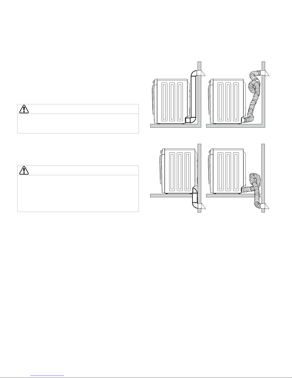
Exhaust system requirements
Use only 4 inch (102 mm) diameter rigid or fl exible
metal duct and approved vent hood which has a swingout damper(s) that open when the dryer is in operation.
When the dryer stops, the dampers automatically close
to prevent drafts and the entrance of insects and rodents.
To avoid restricting the outlet, maintain a minimum of 12
inches (30.5 cm) clearance between the vent hood and the
ground or any other obstruction.
WARNING
FIRE HAZARD
Failure to follow these instructions can create excessive
drying times and fi re hazards.
The following are specifi c requirements for
proper and safe operation of your dryer.
Correct Incorrect
WARNING
FIRE HAZARD
Do not install a clothes dryer with fl exible plastic or
metal foil venting materials. Flexible venting materials
are known to collapse, be easily crushed and trap lint.
These conditions will obstruct clothes dryer airfl ow and
increase the risk of fi re.
If your present system is made up of plastic duct or metal
foil duct, replace it with a rigid or semi-rigid metal duct.
Also, ensure the present duct is free of any lint prior to
installing dryer duct.
Correct Incorrect
6
Page 7

Exhaust system requirements, continued
Installation Requirements
WARNING
FIRE HAZARD
A clothes dryer must be exhausted outdoors. Do not
exhaust dryer into a chimney, a wall, a ceiling, an attic,
a crawl space or any concealed space of a building. A
clothes dryer produces combustible lint. If the dryer is
not exhausted outdoors, some fi ne lint will be expelled
into the laundry area. An accumulation of lint in any
area of the home can create a health and fi re hazard.
The dryer must be connected to an exhaust outdoors.
Regularly inspect the outdoor exhaust opening and remove
any accumulation of lint around the outdoor exhaust
opening and in the surrounding area.
WARNING
FIRE HAZARD
• Do not allow combustible materials (for example:
clothing, draperies/curtains, paper) to come in
contact with exhaust system. The dryer MUST NOT
be exhausted into a chimney, a wall, a ceiling, or any
concealed space of a building which can accumulate
lint, resulting in a fi re hazard.
• Do not screen the exhaust ends of the vent system, or
use any screws, rivets or other fasteners that extend
into the duct to assemble the exhaust system. Lint can
become caught in the screen, on the screws or rivets,
clogging the duct work and creating a fi re hazard
as well as increasing drying times. Use an approved
vent hood to terminate the duct outdoors, and seal
all joints with metal foil duct tape. All male duct pipe
fi ttings MUST be installed downstream with the fl ow
of air.
WARNING
FIRE HAZARD
Exceeding the length of duct pipe or number of elbows
allowed in the “MAXIMUM LENGTH” charts can cause
an accumulation of lint in the exhaust system. Plugging
the system could create a fi re hazard, as well as
increase drying times.
MAXIMUM LENGTH
Number of 90° turns
0 64 ft. (19.5 m) 48 ft. (14.6 m)
1 52 ft. (15.9 m) 40 ft. (12.2 m)
2 44 ft. (13.5 m) 32 ft. (9.8 m)
3 36 ft. (11 m) 24 ft. (7.3 m)
4 28 ft. (9.5 m) 16 ft. (4.9 m)
of 4” (102 mm) Rigid Metal Duct
VENT HOOD TYPE
(Preferred)
4”
(10.2 cm)
louvered
2.5”
(6.35cm)
WARNING
FIRE HAZARD
• Do not install fl exible plastic or fl exible foil venting
material.
• If installing semi-rigid venting, do not exceed 8 ft.
(2.4 m) duct length.
7
Page 8

Installation Requirements
Exhaust system requirements, continued
Install male fi ttings in correct direction:
CORRECT
In installations where the exhaust system has not described
in the previous pages, the following method must be used
to determine if the exhaust system is acceptable:
1 Connect an inclined or digital manometer between
the dryer and the point the exhaust connects to the
dryer.
2 Set the dryer timer and temperature to air fl uff (cool
down) and start the dryer.
3 Read the measurement on the manometer.
4 The system back pressure MUST NOT be higher than
0.75 inches of water column. If the system back
pressure is less than 0.75 inches of water column, the
system is acceptable. If the manometer reading is
higher than 0.75 inches of water column, the system
is too restrictive and the installation is unacceptable.
Although vertical orientation of the exhaust system is
acceptable, the performance of this dryer could be
adversely aff ected by the following conditions:
• The use of non-rigid metal duct work.
• Venting vertically through a roof may expose the
exhaust system to down drafts causing an increase in
vent restriction.
• Running the exhaust system through an uninsulated
area may cause condensation and faster
accumulation of lint.
• Accelerated accumulation of lint buildup in dryer
exhaust system, compression or crimping of the
exhaust system will cause an increase in vent
restriction.
• The exhaust system should be inspected and cleaned
a minimum of every 18 months with normal usage.
The more the dryer is used, the more often you should
check the exhaust system and vent hood for proper
operation.
INCORRECT
Exhaust direction
Directional exhausting can be accomplished by installing
a quick-turn 90° dryer vent elbow directly to the exhaust
outlet of dryer. Dryer vent elbows are available through
your local parts distributor or hardware store.
See also Clearance Requirements on the next page.
NOTE
Use of 90° quick-turn elbow
is required to meet minimum
installation depth of freestanding dryer.
8
Page 9
Manufactured or mobile home installation
Installation Requirements
1 Installation MUST conform to current Manufactured
Home Construction & Safety Standard, Title 24
CFR, Part 32-80 (formerly the Federal Standard for
Mobile Home Construction and Safety, Title 24, HUD
Part 280) or Standard CAN/CSAZ240 MH.
2 Dryer MUST be exhausted outside (outdoors, not
beneath the mobile home) using metal ducting that
will not support combustion. Metal ducting must be
4 inches (10.2 cm) in diameter with no obstructions.
Rigid metal duct is preferred.
3 If dryer is exhausted through the fl oor and area
beneath the mobile home is enclosed, the exhaust
Clearance requirements
WARNING
EXPLOSION HAZARD
Do not install the dryer where gasoline or other
fl ammables are kept or stored. If the dryer is installed
in a garage, it must be a minimum of 18 inches (45.7
cm) above the fl oor. Failure to do so can result in death,
explosion, fi re or burns.
system MUST terminate outside the enclosure with
the termination securely fastened to the mobile
home structure.
4 Refer to previous sections in this guide for other
important exhaust venting system requirements.
5 When installing a gas dryer into a mobile home, a
provision must be made for outside make up air. This
provision is to be not less than twice the area of the
dryer exhaust outlet.
6 Installer MUST anchor this (1) dryer or (2) dryer
mounted on pedestal to the fl oor with approved
Mobile Home Installation Kit - P/N 137067200.
IMPORTANT
DO NOT INSTALL YOUR DRYER:
1 In an area exposed to dripping water or outside
weather conditions.
2 In an area where it will come in contact with
curtains, drapes, or anything that will obstruct the
fl ow of combustion and ventilation air.
3 On carpet. Floor MUST be solid with a maximum
slope of 1 inch (2.5 cm).
9
Page 10
Installation Requirements
Clearance requirements, continued
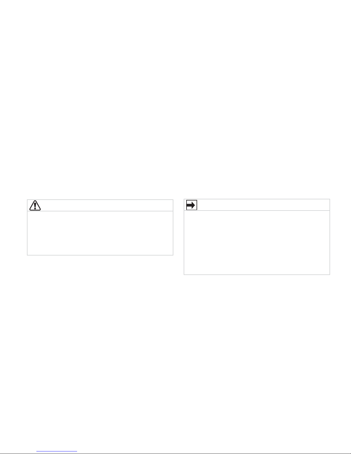
Installation in a Recess or Closet
1 A dryer installed in a bedroom, bathroom, recess or
closet, MUST be exhausted outdoors.
2 No other fuel burning appliance shall be installed in
the same closet as the gas dryer.
3 Your dryer needs the space around it for proper
ventilation.
DO NOT install your dryer in a closet with a solid door.
4 Closet door ventilation required: A minimum of
120 square inches (774.2 cm²) of opening, equally
divided at the top and bottom of the door, is
required. Openings should be located 3 inches (7.6
cm) from bottom and top of door. Openings are
required to be unobstructed when a door is installed.
A louvered door with equivalent air openings for the
full length of the door is acceptable.
3”
(7.6cm)
60 sq. in.
(387.1cm²)
MINIMUM INSTALLATION CLEARANCES - Inches (cm)
SIDES REAR TOP FRONT
Alcove 0” (0 cm) 0” (0 cm)* 0” (0 cm) n/a
Under-
Counter
0” (0 cm) 0” (0 cm)* 0” (0 cm) n/a
Closet 0” (0 cm) 0” (0 cm)* 0” (0 cm) 1” (2.5 cm)
* For other than straight back venting, a quick-turn
90° dryer vent elbow (vented right or down in freestanding dryer or right on pedestal-mounted dryer)
must be installed to achieve 0” (0 cm) installation.
0”
(0cm)
0”
(0cm)
3”
(7.6cm)
closet door
60 sq. in.
(387.1cm²)
1”
(2.54cm)
0”
(0cm)
10
Page 11
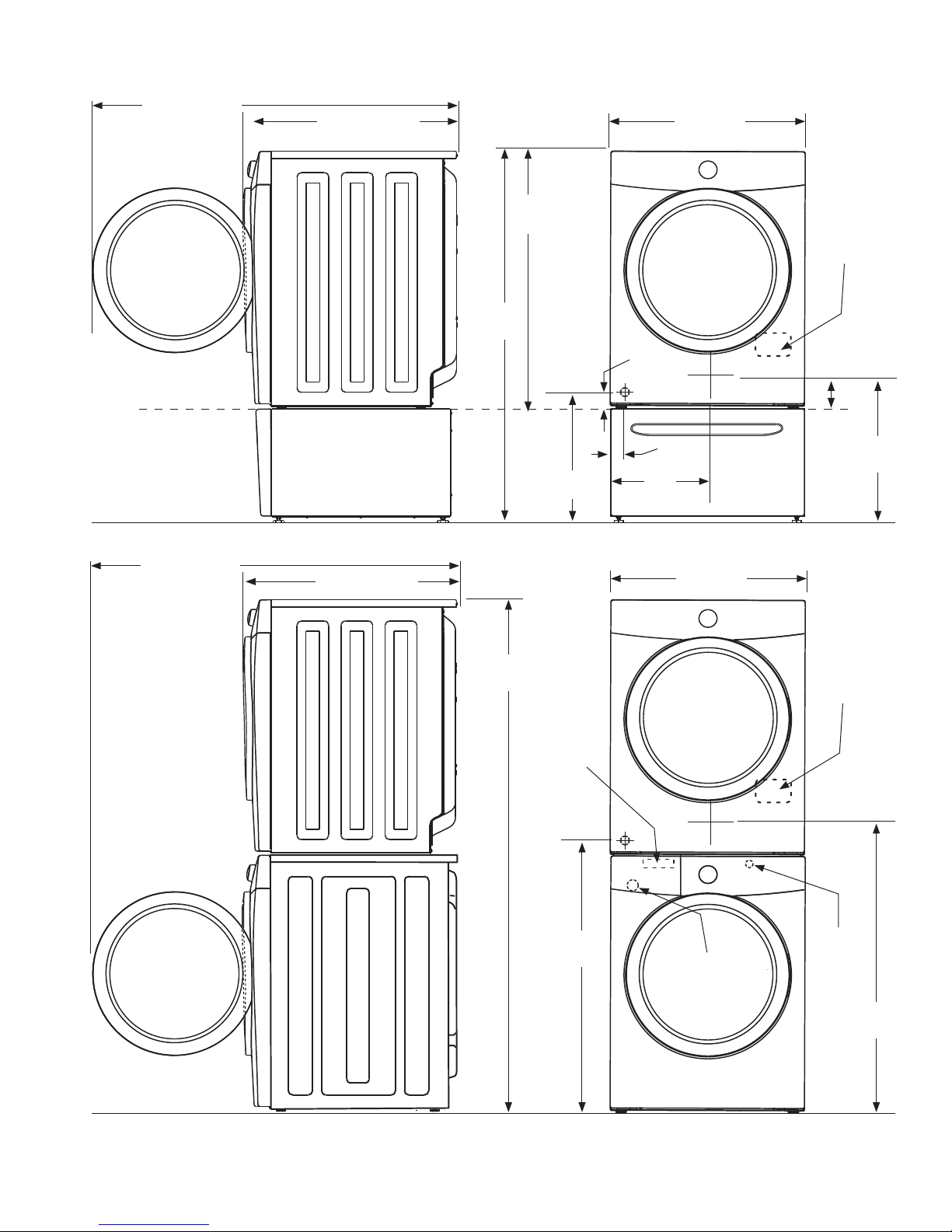
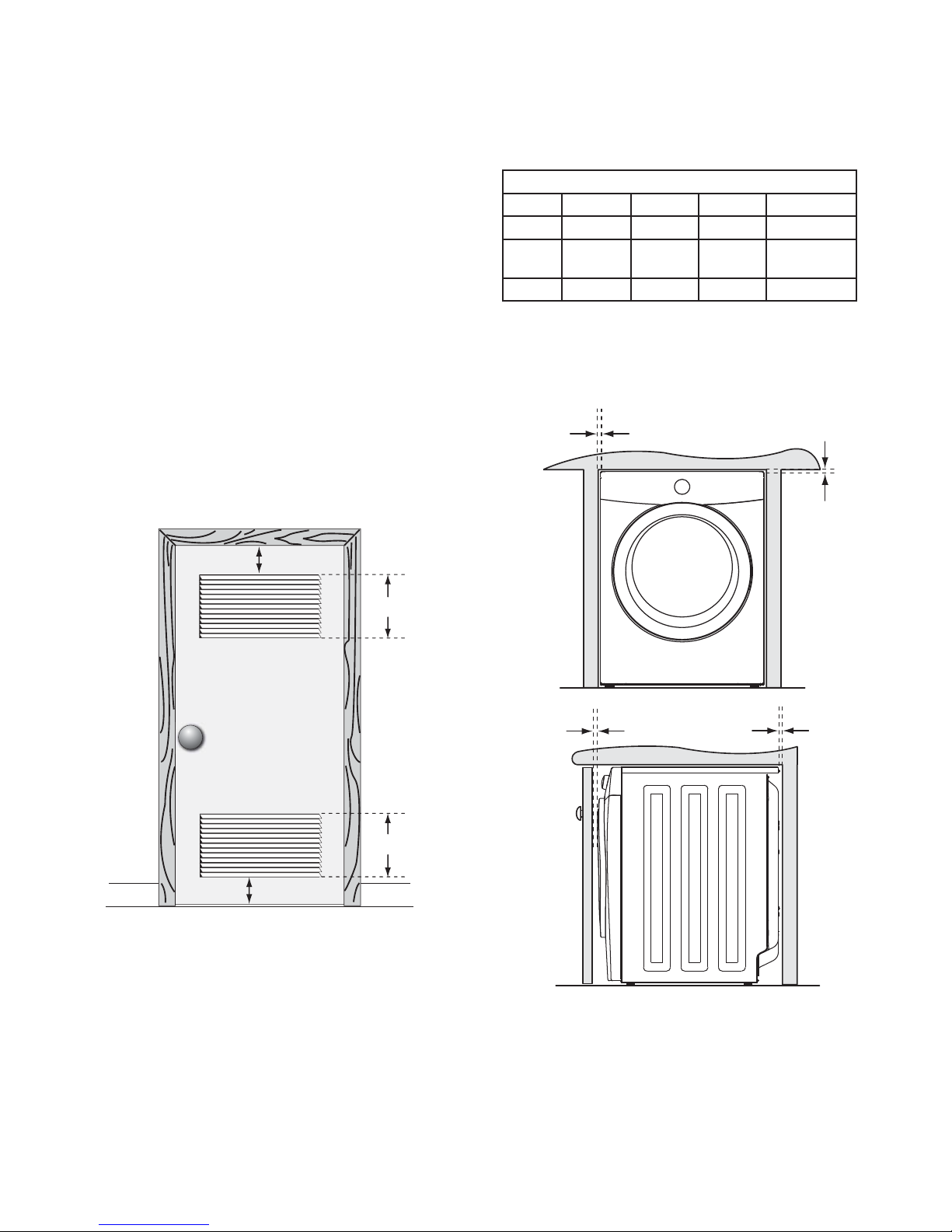
51.4” (131 cm)*
to clear open door
30.3” (77 cm)*
to front of closed door
51.25”
(130 cm)
36.0”
(91.5 cm)
Dryer Dimensions
27.0”
(68.5 cm)
electrical
supply on
rear of unit
1
freestand dryer
fl oor line
dryer mounted on
optional pedestal
fl oor line
51.4” (131 cm)*
to clear open door
on fl oor
30.3” (77 cm)*
to front of closed door
71.5”
(182 cm)
pipe on rear
of gas unit
17.0”
(43 cm)
water supply
connection on
rear of unit
gas supply
pipe on rear
of gas unit
1.6”
(4 cm)gas supply
3.75”
(9.5 cm)
13.50”
(34.5 cm)
to center of rear vent
(68.5 cm)
27.0”
centerline height
for rear vent
3.7”
(9.5 cm)
19.0”
(48 cm)
electrical
supply on
rear of unit
centerline
height for
rear vent
1
fl oor line
*Connection of water inlet hose on steam dryer adds 3/4 in. (2 cm) to installation depth.
1
Power supply cord length on gas dryer approximately 60 inches (152.5 cm).
2
Drain hose length on washer approximately 59 inches (150 cm).
3
Power supply cord length on washer approximately 60 inches (152.5 cm).
37”
(94 cm)
drain hose on
rear of unit
2
power cord on
rear of unit
3
(99 cm)
39”
11
Page 12
Installation Instructions
Electrical installation
The following are specifi c requirements for proper and
safe electrical installation of your dryer. Failure to follow
these instructions can create electrical shock and/or a fi re
hazard.
WARNING
ELECTRICAL SHOCK HAZARD
• This appliance MUST be properly grounded.
Electrical shock can result if the dryer is not properly
grounded. Follow the instructions in this manual for
proper grounding.
• Do not use an extension cord with this dryer. Some
extension cords are not designed to withstand the
amounts of electrical current this dryer utilizes
and can melt, creating electrical shock and/
or fi re hazard. Locate the dryer within reach of
the receptacle for the length power cord to be
purchased, allowing some slack in the cord. Refer to
the pre-installation requirements in this manual for
the proper power cord to be purchased.
WARNING
ELECTRICAL SHOCK HAZARD
• A U.L.-approved strain relief must be installed onto
power cord. If the strain relief is not attached, the
cord can be pulled out of the dryer and can be cut
by any movement of the cord, resulting in electrical
shock.
• Do not use an aluminum wired receptacle with a
copper wired power cord and plug (or vice versa).
A chemical reaction occurs between copper and
aluminum and can cause electrical shorts. The proper
wiring and receptacle is a copper wired power cord
with a copper wired receptacle.
NOTE
Dryers operating on 208 volt power supply will have
longer drying times than dryers operating on 240 volt
power supply.
Grounding requirements - Electric dryer (USA)
WARNING
ELECTRICAL SHOCK HAZARD
Improper connection of the equipment grounding
conductor can result in a risk of electrical shock. Check
with a licensed electrician if you are in doubt as to
whether the appliance is properly grounded.
For a grounded, cord-connected dryer:
1 The dryer MUST be grounded. In the event of a
malfunction or breakdown, grounding will reduce
the risk of electrical shock by a path of least
resistance for electrical current.
2 After you purchase and install a 3 wire or 4 wire
power supply cord having an equipment-grounding
conductor and a grounding plug that matches your
3 DO NOT modify the plug you’ve installed on this
For a permanently connected dryer:
1 The dryer MUST be connected to a grounded
wiring system, the plug MUST be plugged into
an appropriate, copper wired receptacle that is
properly installed and grounded in accordance with
all local codes and ordinances. If in doubt, call a
licensed electrician.
appliance. If it will not fi t the outlet, have a proper
outlet installed by a qualifi ed electrician.
metal, permanent wiring system; or an equipment
grounding conductor must be run with the circuit
conductors and connected to the equipmentgrounding terminal or lead on the appliance.
12
Page 13

Grounding type
ll receptacle
wer cord with
3-prong grgr
ounded plug
Do not,
under
y cir
cumstances,
cut,
removeve,
or b
ypass the
ounding pr
ong.
Grounding requirements - Electric dryer (Canada)
Installation Instructions
WARNING
ELECTRICAL SHOCK HAZARD
Improper connection of the equipment grounding
conductor can result in a risk of electrical shock. Check
with a licensed electrician if you are in doubt as to
whether the appliance is properly grounded.
the risk of electrical shock by providing a path of
least resistance for electrical current.
2 Since your dryer is equipped with a power supply
cord having an equipment-grounding conductor and
a grounding plug, the plug must be plugged into
an appropriate outlet that is properly installed and
grounded in accordance with all local codes and
ordinances. If in doubt, call a licensed electrician.
For a grounded, cord-connected dryer:
1 The dryer MUST be grounded. In the event of a
malfunction or breakdown, grounding will reduce
3 DO NOT modify the plug provided with this
appliance. If it will not fi t the outlet, have a proper
outlet installed by a qualifi ed electrician.
Grounding requirements - Gas dryer (USA and Canada)
1 The dryer is equipped with a three-prong
(grounding) plug for your protection against shock
hazard and should be plugged directly into a
properly grounded three-prong receptacle.
2 The plug must be plugged into an appropriate
outlet that is properly installed and grounded in
accordance with all local codes and ordinances. If
in doubt, call a licensed electrician.
3 DO NOT modify the plug provided with this
appliance. If it will not fi t the outlet, have a proper
outlet installed by a qualifi ed electrician.
Grounding type
wawall receptacl
Do not,
under
anany cir
cumstances,
cut,
remo
or b
ypass th
grgrounding pr
ong.
13
PoPower cord with
3-prong
ounded plug
Page 14
Installation Instructions
Gas connection
1 Remove the shipping cap from gas pipe at the rear
of the dryer.
IMPORTANT
DO NOT connect the dryer to L.P. gas service without
converting the gas valve. An L.P. conversion kit must be
installed by a qualifi ed gas technician.
2 Connect a 1/2 inch (1.27 cm) I.D. semi-rigid or
approved pipe from gas supply line to the 3/8 inch
(0.96 cm) pipe located on the back of the dryer. Use
a 1/2 inch to 3/8 inch (1.27 cm to 0.96 cm) reducer
for the connection. Apply an approved thread sealer
that is resistant to the corrosive action of liquefi ed
gases on all pipe connections.
Closed
Manual
Shuto
Valve
Open
Flare
Union
All connections must be wrench-tightened
elppiN
GAS FLOW
Flexible
Connector
Flare
Union
Inlet Pipe on
Back of Dryer
3 Open the shutoff valve in the gas supply line to
allow gas to fl ow through the pipe. Wait a few
minutes for gas to move through the gas line.
to dryer
from gas supply
Shuto Valve -
Open position
4 Check for gas system leaks with a manometer. If a
manometer is not available, test all connections by
brushing on a soapy water solution.
WARNING
EXPLOSION HAZARD
NEVER test for gas leaks with an open fl ame.
IMPORTANT
The supply line must be equipped with an approved
manual shutoff valve. This valve should be located in the
same room as the dryer and should be in a location that
allows ease of opening and closing. Do not block access
to the gas shutoff valve.
14
Page 15

Installation Instructions
Water connection for Add Steam function (steam models only)
WATER SUPPLY REQUIREMENTS
Cold water faucet MUST be installed within 42 inches
(107 cm) of your dryer’s water inlet. The faucet MUST be
3/4 inch (1.9 cm) and have threading for laundry hose
connection. Water pressure MUST be between 30 and 120
psi. Your water department can advise you of your water
pressure.
1 Turn off COLD water supply to washer.
2 Remove COLD inlet hose from COLD water supply
and inspect for rubber washer. Replace washer if it
is torn or worn out.
RUBBER WASHER
MUST BE PRESENT
AND UNDAMAGED
COLD INLET HOSE
TO WASHER
3 Momentarily turn on COLD supply and run some
water into a bucket or container to clear any
contaminants in the line.
4 Remove hose kit from dryer drum and inspect hose
couplings for proper placement of rubber washers.
RUBBER WASHERS
MUST BE PRESENT
15
Page 16

Installation Instructions
Water connection, continued
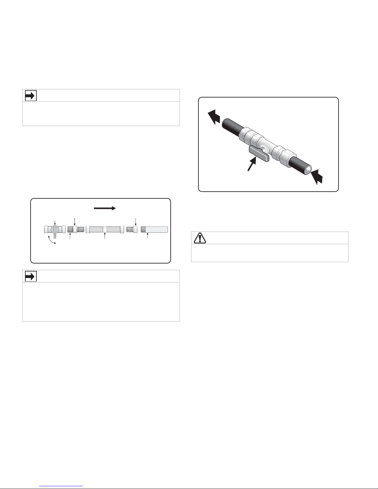
5 If your installation has room for the COLD water
supply to accept the “Y” connector directly, thread
the “Y” connector to the COLD water supply and
tighten it by hand until snug; then tighten it another
2/3 turn with pliers.
NOTE
If you were able to install the “Y” connector directly to
the COLD water supply, please skip to step 8.
6 If there is not enough room to install the “Y”
connector directly, thread a short extension hose
onto the COLD water supply and tighten it by hand
until snug; then tighten it another 2/3 turn with
pliers.
NOTE
Short extension available from your local hardware
supplier. Extension hose must meet qualifi cations for use
in laundry installation.
7 Thread the “Y” connector to the short extension hose
and tighten it by hand until snug; then tighten it
another 2/3 turn with pliers.
8 Connect the COLD inlet hose for the washer to the
“Y” connector and tighten it by hand until snug; then
tighten it another 2/3 turn with pliers.
9 Connect the straight end of the long hose from the
kit to the other outlet on the “Y” connector and
snug it by hand. Connect the hose’s 90° coupling
to the brass water inlet on the back of the dryer
and tighten it by hand until snug. Tighten each
connection of the dryer inlet hose another 2/3 turn
with pliers.
10 Turn on the water and check for leaks at all
connections.
DIRECT CONNECTION
OR WITH EXTENSION*
WATER INLET
ON DRYER
COLD WATER SUPPLY
HOSE TO WASHER
*Laundry hose extension not included with dryer.
16
Page 17

Electrical connection (non-Canada) - 3 wire cord
Internal ground
(GREEN screw)
Install
UL-approved
strain relief here
Terminal screw
recovery slot
Line 1
(BRASS terminal)
Neutral
(SILVER terminal)
Line 2
(BRASS terminal)
Access cover
screw
Terminal
block
Neutral
(center wire)
30 AMP
NEMA 10-30
DO NOT remove
internal ground in
a 3-wire system!!
Neutral
terminal
Failure to disconnect power source before servicing
could result in personal injury or even death.
1 Turn off power supply to outlet.
2 Remove the screw securing the terminal block access
3 Install a UL-approved strain relief according to the
4 Thread an UNPLUGGED, UL-approved, 30 amp.
5 Attach the power cord neutral (center wire)
6 Attach the remaining two power cord outer
• Do not make a sharp bend or crimp wiring/conductor
• DO NOT remove the internal ground from the GREEN
7 Follow manufacturer’s guidelines for fi rmly securing
8 Reinstall the terminal block cover.
If moving dryer from a 4-wire system and installing it
in a 3-wire system, move the internal ground from the
center terminal back to the GREEN screw next to the
terminal block.
3-wire receptacle
(NEMA type 10-30R)
WARNING
ELECTRICAL SHOCK HAZARD
cover in the lower corner on the back of the dryer.
power cord/strain relief manufacturer’s instructions
in the power cord entry hole below the access panel.
At this time, the strain relief should be loosely in
place.
power cord, NEMA 10-30 type SRDT, through the
strain relief.
conductor to the SILVER colored center terminal on
the terminal block. Tighten the screw securely.
conductors to the outer, BRASS colored terminals on
the terminal block. Tighten both screws securely.
WARNING
ELECTRICAL SHOCK HAZARD
at connections.
screw next to the terminal block.
the strain relief and power cord.
IMPORTANT
Installation Instructions
30 AMP
NEMA 10-30
NOTE
If a terminal screw falls during cord installation, it can
be retrieved in the terminal screw recovery slot below
the access panel.
DO NOT remove
internal ground in
a 3-wire system!!
Neutral
(center wire)
Access cover
screw
Terminal
block
Line 2
(BRASS terminal)
Neutral
(SILVER terminal)
Line 1
(BRASS terminal)
Internal ground
(GREEN screw)
Install
UL-approved
strain relief here
Terminal screw
recovery slot
Neutral
terminal
17
Page 18

Neutral
(WHITE wire)
30 AMP
NEMA 14-30
Ground
(GREEN wire)
Move internal ground (WHITE)
wire to neutral (SILVER)
terminal for 4-wire system.
Neutral
terminal
GREEN
ground screw
BLACK or
RED power wire
BLACK
or RED
power wire
GREEN
ground wire
WHITE
neutral wire
Internal ground
(GREEN screw)
Install
UL-approved
strain relief here
Terminal screw
recovery slot
Line 1
(BRASS terminal)
Neutral
(SILVER terminal)
Line 2
(BRASS terminal)
Access cover
screw
Terminal
block
Installation Instructions
Electrical connection (non-Canada) - 4 wire cord
4-wire receptacle
(NEMA type 14-30R)
WARNING
ELECTRICAL SHOCK HAZARD
Failure to disconnect power source before servicing
could result in personal injury or even death.
1 Turn off power supply to outlet.
2 Remove the screw securing the terminal block access
cover in the lower corner on the back of the dryer.
3 Install a UL-approved strain relief according to the
power cord/strain relief manufacturer’s instructions
in the power cord entry hole below the access panel.
At this time, the strain relief should be loosely in
place.
4 Thread an UNPLUGGED, UL-approved, 30 amp.
power cord, NEMA 14-30 type ST or SRDT, through
the strain relief.
5 Disconnect the dryer internal ground wire (WHITE)
from the ground screw (GREEN) next to the terminal
block.
6 Attach the power cord ground wire (GREEN) to the
ground screw (GREEN) next to the terminal block.
Tighten the screw securely.
7 Move the dryer internal ground wire (WHITE) to the
terminal block and attach it along with the neutral
(WHITE) power cord wire conductor to the center,
SILVER colored terminal on the terminal block.
Tighten the screw securely.
8 Attach the RED and BLACK power cord conductors
to the outer, BRASS colored terminals on the terminal
block. Tighten both screws securely.
NOTE
If a terminal screw falls during cord installation, it can
be retrieved in the terminal screw recovery slot below
the access panel.
Move internal ground (WHITE)
wire to neutral (SILVER)
terminal for 4-wire system.
30 AMP
NEMA 14-30
Ground
(GREEN wire)
Access cover
(BRASS terminal)
(SILVER terminal)
(BRASS terminal)
Internal ground
(GREEN screw)
UL-approved
strain relief here
Terminal screw
recovery slot
Neutral
terminal
Neutral
(WHITE wire)
screw
Terminal
block
Line 2
Neutral
Line 1
Install
WARNING
Do not make a sharp bend or crimp wiring/conductor at
connections.
ELECTRICAL SHOCK HAZARD
9 Follow manufacturer’s guidelines for fi rmly securing
the strain relief and power cord.
10 Reinstall the terminal block cover.
18
GREEN
ground screw
ground wire
GREEN
RED power wire
WHITE
neutral wire
BLACK
or RED
power wire
BLACK or
Page 19
General installation
Grounding type
ll receptacle
wer cord with
3-prong grgr
ounded plug
Do not,
under
y cir
cumstances,
cut,
removeve,
or b
ypass the
ounding pr
ong.
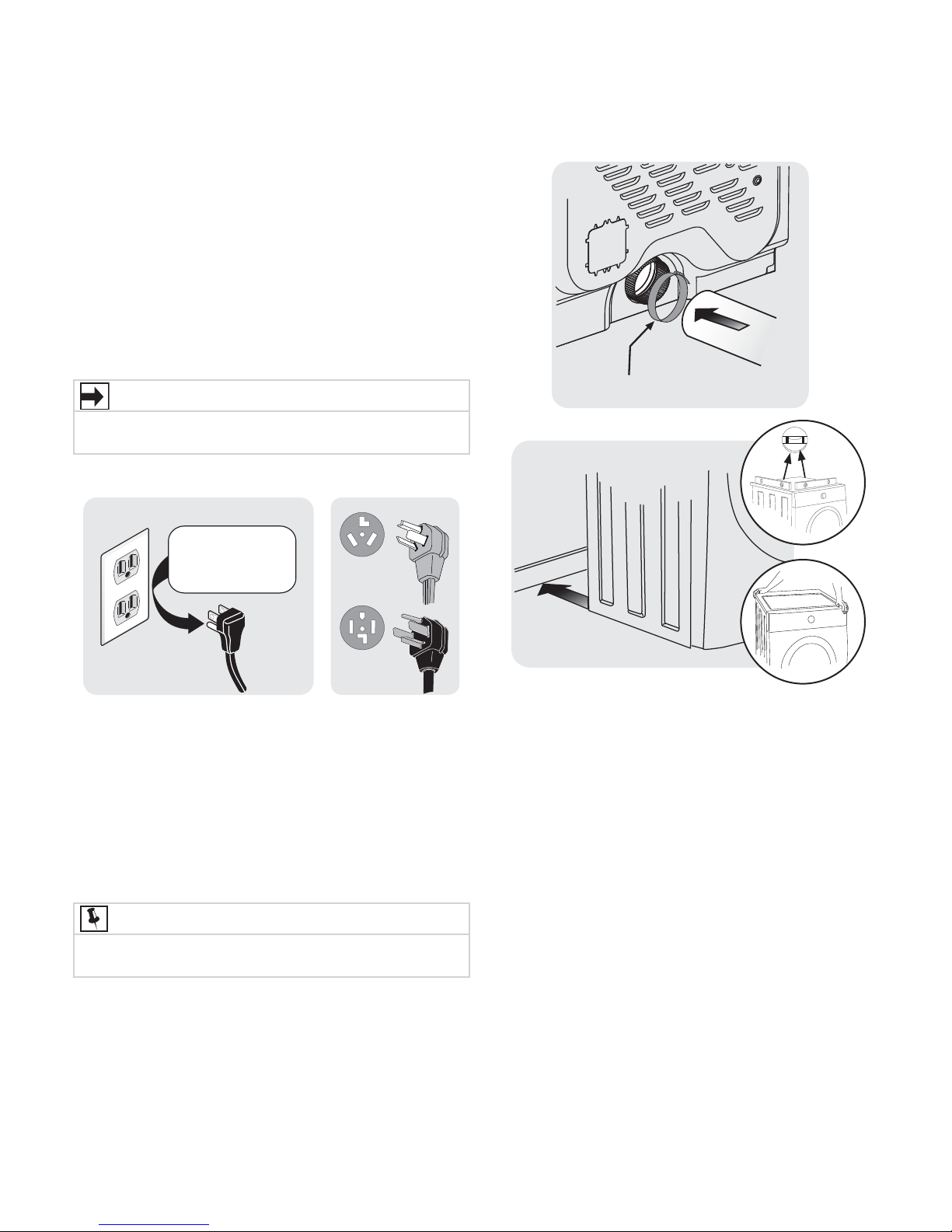
1 Connect the exhaust duct to the outside exhaust
system. Use of a 4” (102 mm) clamp (item A) is
recommended to connect the dryer to the exhaust
vent system. Use metal foil tape to seal all other
joints.
2 Carefully slide the dryer to its fi nal position. Adjust
one or more of the legs until the dryer is resting
solidly on all four legs. Place a level on top of the
dryer. The dryer MUST be level and resting solidly
on all four legs. Rock alternating corners to check
for stability. Remove and discard door tape.
Installation Instructions
IMPORTANT
Be sure the power is off at a circuit breaker/fuse box
before plugging the power cord into an outlet.
3 Plug the power cord into a grounded outlet.
Grounding type
wawall receptacl
PoPower cord with
3-prong
4 Turn on the power at the circuit breaker/fuse box.
5 Read the
It contains valuable and helpful information that will
save you time and money.
6 If you have any questions during initial operation,
please review the “Avoid Service Checklist” in your
Use & Care Guide
7 Place these instructions in a location near the dryer
for future reference.
Do not,
under
anany cir
cumstances,
cut,
remo
or b
ypass th
grgrounding pr
ounded plug
Use & Care Guide
before calling for service.
ong.
provided with the dryer.
A
NOTE
A wiring diagram and technical data sheet are located
under the dryer top panel.
19
Page 20

Reversing Door Swing
1. Be sure you have adequate swing area before
reversing door.
2. You will need a screw driver with a #2 square
and straight bit.
3. Protect fl at work surface, such as top of dryer or
fl oor near dryer, with a soft cloth or towel.
4. Be sure dryer is unplugged from power source!
Removing the door
1. Protect fl at work surface, such as top of dryer or fl oor
near dryer, with a soft cloth or towel.
2. Open dryer door and remove the two hinge screws.
Remove lower screw fi rst, then upper screw.
WARNING
ELECTRICAL SHOCK HAZARD
Failure to disconnect power source
before servicing could result in personal
injury or even death.
4. Gently place dryer door face down on fl at, covered
work surface.
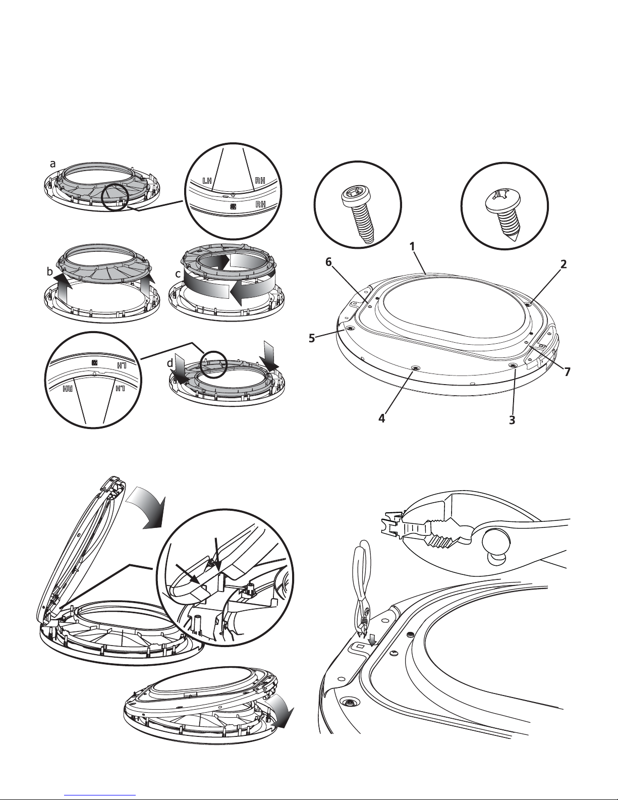
5. Locate the 5 indented head screws (no. 1-5) in the small,
circular recesses (at 11, 1, 4, 6, and 8 o’clock positions)
of the inner door. Remove and save these 5 screws.
Tools needed:
Screwdrivers with
#2 square &
straight bit
3. Supporting door with both hands, squarely lift door and
hinge upward approximately 3/8” (10 mm) so “T” post
on back of hinge can slide out through “T” slot on front
panel.
“T” SLOT IN
FRONT PANEL
“T” POST ON
DOOR HINGE
IMPORTANT
Do not attempt to remove the 2 “tamper-resistant”
screws that hold the inner glass in place.
6. Locate the 2 pan head screws (no. 6-7) on the inner
door nearest the metal strike and center of hinge (9
and 3 o’clock positions). Remove and save these 2
screws.
7. Separate inner door assembly from outer door
assembly.
20
Page 21

Reversing the hinge
Reversing Door Swing
1. Carefully pull out the 2 small round hole plugs from the
front panel and save. Remove and save the square “T”
slot cover by sliding it up and pulling it out. Move all 3
plugs to the opposite side of the front panel and insert.
ROUND PLUG
SQUARE PLUG
ROUND PLUG
2. Turn inner door assembly over to expose retaining tabs
of metal strike. Grip tabs fully with pliers to remove.
Discard old metal strike.
4. From the back side of the inner door, pinch the
retaining tabs of the plastic square plug to release it.
Save square plug for reinstallation.
5. Carefully remove the 2 round plugs from the inner door
and move them to the opposite holes and reinstall.
OUT
3. Turn the inner door assembly back over and locate
the 2 pan head hinge screws. Remove and save the
2 screws and separate the hinge from inner door
assembly.
HINGE SCREWS
IN
6. Rotate the hinge and move it to the opposite side of
the inner door. Attach it with the 2 pan head screws
removed previously. Reinstall plastic plug in the square
hole next to the hinge.
21
Page 22
Reversing Door Swing
Reassembling the door
1. Lift the inner glass ring. Rotate it 180 degrees, reinstall
on outer door, lining up indicators - “LH” for left-hand
hinge or “RH” for right-hand hinge.
3. Replace indented head screws (no. 1-5) removed earlier.
Take care not to strip out the plastic holes.
4. Replace pan head screws (no. 6-7) removed earlier.
Take care not to strip out the plastic holes.
no. 1-5
no. 6-7
2. Rest the opening of the inner door at a 90 degree
angle on the supports for the hinge cutout cover. Pivot
the inner door down onto the outer door.
5. Locate new metal strike supplied with dryer manuals.
Grip new strike with pliers as shown below. Firmly insert
the strike so it is oriented vertically.
22
Page 23

Reattaching the door
Reversing Door Swing
1. Holding the door in both hands, squarely insert the “T”
post on the back of the hinge into the “T” slot on the
front panel and lower it to align the mounting holes.
“T” SLOT IN
“T” POST ON
DOOR HINGE
FRONT PANEL
3. Close the door and test operation of hinge, strike and
latch.
2. While supporting the door, install the upper pan head
screw fi rst and then the lower one.
NOTE
Correctly installed hinge screws will press hinge fl ush to
front panel. Any gap between hinge and front panel will
cause misalignment of strike to latch.
23
Page 24

Accessories
26.5”
(67 cm)
15.0”
(38 cm)
27.0”
(68.5 cm)
MATCHING STORAGE PEDESTAL*
White Pedestal - ITEM# 90092
Silver Pedestal - ITEM# 90097
A storage pedestal accessory, specifi cally designed for this
dryer may be used to elevate the washer for ease of use. This
pedestal will add about 15.25” (39 cm) to the height of your
unit for a total height of 51.25” (130 cm).
*Other colors may be available. Contact the source where you
purchased your dryer.
DRYER STACKING KIT
ITEM# 10050
Depending on the model you purchased, a kit for stacking this
dryer on top of matching washer may have been included in
the initial purchase of your dryer. If your model did not include
a stacking kit or you desire another stacking kit, you may order
one.
LP CONVERSION KIT
ITEM# 38239
Gas dryers intended for use in a location supplied with LP must
use a conversion kit prior to installation.
MOBILE HOME INSTALLATION KIT
P/N 137067200
Installation in a mobile home requires the use of a MOBILE
HOME INSTALLATION KIT.
CAUTION
Failure to use accessories manufactured by (or
approved by) the manufacturer could result in personal
injury, property damage or damage to the dryer.
27.0”
(68.5 cm)
15.0”
(38 cm)
26.5”
(67 cm)
DRYING RACK
P/N 137067300
Depending on the model you purchased, a drying rack may
have been included in the initial purchase of your dryer. If
your model did not include a drying rack or you desire another
drying rack, you may order one.
UNIVERSAL APPLIANCE WRENCH
P/N 137019200
A UNIVERSAL APPLIANCE WRENCH is available to aid in
dryer/washer/pedestal feet adjustment.
TOUCH UP PAINT PENS*
White Touch Up Pen - P/N 5304468812
Silver Touch Up Pen - P/N 5304471228
*Other colors may be available. Contact the source where you
purchased your dryer.
Replacement parts:
If replacements parts are needed for your dryer,
contact the source where you purchased your washer or
refer to your
Use and Care Guide
for more information.
WARNING
ELECTRICAL SHOCK HAZARD
Label all wires prior to disconnection when servicing controls.
Wiring errors can cause improper and dangerous operation.
Verify proper operation after servicing.
24
Page 25

Instrucciones Importantes de Seguridad
ADVERTENCIA
Para su seguridad, debe seguir la información de esta guía para minimizar el riesgo de incendio o explosión o para
evitar daños a la propiedad, lesiones personales o incluso la muerte. No almacene ni utilice gasolina ni otros líquidos o
vapores infl amables cerca de este o de cualquier otro electrodoméstico.
ADVERTENCIA - PELIGRO DE INCENDIO
Lea las siguientes instrucciones antes de instalar y utilizar este electrodoméstico:
• Después de desembalar la secadora, destruya los cartones y las bolsas de plástico. Los niños podrían utilizarlos para
jugar. Los cartones cubiertos con alfombras, cubrecamas, o láminas de plástico pueden convertirse en cámaras de
aire herméticamente cerradas y provocar asfi xia. Coloque todos los materiales en un basurero o manténgalos fuera
del alcance de los niños.
• La instalación y el servicio de la secadora de ropa deben ser llevados a cabo por un instalador califi cado, agencia
de servicios o proveedor de gas.
• Instale la secadora de ropa de acuerdo con las instrucciones del fabricante y los códigos locales.
• La reparación eléctrica de la secadora debe cumplir con los códigos y las ordenanzas locales y la última edición del
Código Eléctrico Nacional (National Electrical Code), el ANSI/NFPA 70, o bien en Canadá, el CSA C22.1 del Código
Eléctrico de Canadá (Canadian Electrical Code) Parte 1.
• El servicio de gas de la secadora debe cumplir con los códigos y las ordenanzas locales, y la última edición del Código de Gas Nacional (National Fuel Gas Code), el ANSI Z223.1, o bien en Canadá, el CAN/CGA B149,1-2000.
• La secadora se diseñó conforme a los códigos ANSI Z 21.5.1 o ANSI/UL 2158 - CAN/CSA C22.2 N.º 112 (últimas
ediciones) solo para USO DOMÉSTICO. No se recomienda esta secadora para uso comercial, como por ejemplo, en
restaurantes, salones de belleza, etc.
• No utilice materiales de ventilación de plástico ni de papel de aluminio fl exibles para instalar la secadora de ropa.
Por lo general, dichos materiales se desarman, se deterioran con facilidad y acumulan pelusa. Estas condiciones obstruyen el fl ujo de aire de la secadora y aumentan el riesgo de incendio.
• No apile la secadora sobre la lavadora si ya está instalada sobre un pedestal. No apile la lavadora sobre la secadora. No apile la lavadora sobre otra lavadora.
• Las instrucciones de esta guía y todo el material que se incluye con esta secadora no tienen como propósito cubrir
todas las condiciones y situaciones que puedan presentarse. Cuando instale, opere o repare cualquier artefacto DEBE
tener cuidado y hacer uso de buenas prácticas de seguridad.
QUÉ HACER SI SIENTE OLOR A GAS:
• No intente encender ningún electrodoméstico.
• No toque ningún interruptor eléctrico; no utilice ningún
teléfono en la vivienda.
• Despeje la habitación, el edifi cio o el área de todos
los ocupantes.
• Llame inmediatamente a su proveedor de gas desde el
teléfono de un vecino. Siga las instrucciones del proveedor de gas.
• Si no puede ponerse en contacto con el proveedor de
gas, llame a los bomberos.
Requisitos de preinstalación
Herramientas y materiales necesarios para la instalación:
• Pinzas ajustables
• Destornilladores Philips con punta
derecha y cuadrada
• Llave ajustable
• Llave para tubos de suministro de
gas
• Cinta aislante resistente al gas LP
(para suministro de gas natural o LP)
• Nivel de carpintero
• Capucha de ventilación externa
• Conducto de escape de metal rígido
o semirígido de 4 pulgadas (102 mm)
• Kit de cables de alimentación trifi lar
o tetrafi lar de 240 voltios (secadora
eléctrica)
• Abrazadera de 4” (10,2 cm)
PRECAUCIÓN
PELIGRO DE EXCESO DE PESO
Para evitar lesiones en la espalda u otro tipo de lesiones,
procure levantar o mover la secadora con la ayuda de
más de una persona.
Conserve estas instrucciones
para referencia futura.
• Válvula de cierre de línea de gas
(secadora a gas)
• Adaptadores NPI de unión acampanada (x2) y línea fl exible de suminis-
tro de gas (secadora a gas) de ½’
(15,2 cm)
• Cinta de papel aluminio (no cinta
adhesiva aislante)
Page 26

Instrucciones Importantes de Seguridad
ADVERTENCIA
Lea todas las instrucciones antes de usar este secadora.
Identifi cación de los símbolos, palabras
y avisos de seguridad
Las indicaciones de seguridad incluidas en este manual
aparecen precedidas de un aviso titulado “ADVERTENCIA”
o “PRECAUCIÓN”, de acuerdo con el nivel de riesgo.
Defi niciones
Este es el símbolo de alerta de seguridad. Se usa para
alertar sobre peligros potenciales de lesiones personales.
Obedezca todos los mensajes de seguridad que tengan este
símbolo para evitar posibles lesiones personales o la muerte.
PELIGRO
PELIGRO indica una situación de peligro inminente que,
si no se evita, podría causar lesiones graves o la muerte.
ADVERTENCIA
ADVERTENCIA indica una situación potencialmente
peligrosa que, si no se evita, podría causar lesiones
personales graves o la muerte.
PRECAUCIÓN
PRECAUCIÓN indica una situación potencialmente
peligrosa que, si no se evita, podría causar lesiones
personales leves o moderadas.
IMPORTANTE
IMPORTANTE indica información de instalación,
funcionamiento o mantenimiento que es importante,
pero que no está relacionada con la seguridad.
ÍNDICE
Instrucciones importantes de seguridad ......................25-26
Requisitos de instalación .............................................. 27-33
Dimensiones de la secadora .............................................. 34
Instrucciones de instalación ......................................... 35-43
Inversión de la puerta ...................................................44-46
Accesorios ............................................................................. 47
Lista de Verifi cación
de Instalación
Ventilación de escape
De fl ujo libre y sin acumulación de pelusa
Conductos rígidos o semirígidos de 4” (102 mm)
de distancias y giros mínimos
SIN materiales de ventilación de aluminio o de
plástico
El sistema de evacuación debe ventilar al
exterior y contar con una capucha de ventilación
aprobada
Nivelación
La secadora está nivelada de lado a lado y de
adelante hacia atrás
El secadora descansa fi rmemente sobre sus cuatro
esquinas
Suministro de agua (agregar vapor)
Se instalaron la arandela de goma (empacada
en el tambor) en manguera de admisión NUEVA
(empacada en el tambor)
La manguera de admisión debe estar conectada
al conector en “Y” del suministro de agua FRÍA.
Se abrió el suministro de agua
No hay escapes en las conexiones del suministro
de agua o en las conexiones de admisión del
electrodoméstico vuelva a verifi car a las 24 horas
Suministro de gas (secadora a gas)
Válvula de cierre manual instalada en la tubería
de suministro
Todas las conexiones selladas con un sellante
aprobado y bien apretadas con una llave
Kit de conversión para el sistema de gas LP
Suministro de gas abierto
No hay escapes en ninguna conexión:
verifi que con agua jabonosa, NUNCA con una
llama
Suministro eléctrico de 240V (secadora
eléctrica)
Cordón de servicio eléctrico 10-30R o 10-40R
aprobado por la NEMA con todos los tornillos
bien apretados en el tablero de terminales
Dispositivo de liberación de tensión aprobado
Tapa de acceso a los terminales instalada antes
del primer uso
Inversión de la puerta
Siga las instrucciones detalladas en esta guía
Pruebe la bisagra y el gancho para asegurarse de
que funcionen
Suministro eléctrico
El suministro eléctrico del hogar está activado
La secadora está enchufada
Inspección fi nal
Lea bien las instrucciones de instalación y la guía
de uso y cuidado
La puerta se cierra y el tambor gira cuando se
inicia el ciclo
26
Page 27

Requisitos de Instalación
NOTA
Debido a posibles variaciones en el voltaje, no se recomienda utilizar esta secadora con electricidad generada a
partir de generadores a gas, solares, eólicos ni de ninguna otra clase que no sean los empleados por su empresa de
electricidad local.
Requisitos eléctricos de la secadora eléctrica
CIRCUITO: circuito independiente individual de 30 amp. con fusibles de acción retardada o disyuntores. Use circuitos con
fusibles separados para la lavadora y la secadora. NO haga funcionar una lavadora y una secadora en el mismo
circuito.
SUMINISTRO ELÉCTRICO: trifi lar o tetrafi lar, 240 V, 1 fase, 60 Hz, corriente alterna.
IMPORTANTE
A menos que haya sido fabricada para la venta en Canadá, esta secadora está conectada a tierra internamente a
través de un enlace a un conductor neutro. La conexión a tierra a través del neutro está prohibida para: (1) instalaciones
de circuitos de bifurcación nuevos; (2) casas rodantes; (3) vehículos recreativos; y (4) áreas cuyas leyes locales no
permiten la puesta a tierra a través del neutro.
RECEPTÁCULO DEL TOMACORRIENTE - receptáculo NEMA 10-30 R o NEMA 14-30 R que debe estar ubicado en un
lugar al que pueda acceder el cable de alimentación eléctrica cuando la secadora esté instalada.
CONEXIÓN A TIERRA: consulte “Requisitos de conexión a tierra” en la sección Instalación eléctrica.
CABLE DE ALIMENTACIÓN ELÉCTRICA TRIFILAR (no
incluido)
Receptáculo trifi lar
(tipo NEMA 10-30R)
La secadora DEBE emplear un cable de alimentación
eléctrica de 3 conductores tipo NEMA 10-30, SRDT
califi cado para CA mínima de 240 voltios, 30
amp., con 3 conectores de terminal horquilla con
extremos doblados hacia arriba o de bucle cerrado
y califi cados para uso en secadoras de ropa. Para
obtener instrucciones sobre la conexión trifi lar, consulte
CONEXIONES ELÉCTRICAS PARA UN SISTEMA
TRIFILAR.
CABLE DE ALIMENTACIÓN ELÉCTRICA TETRAFILAR (no
incluido)
Receptáculo tetrafi lar
(tipo NEMA 14-30R)
La secadora DEBE emplear un cable de alimentación
eléctrica de 4 conductores tipo NEMA 14-30, SRDT o
ST (según se especifi que) califi cado para CA mínima
de 240 voltios, 30 amp., con 4 conectores de terminal
horquilla con extremos doblados hacia arriba o de
bucle cerrado y califi cados para uso en secadoras
de ropa. Para obtener instrucciones sobre la conexión
tetrafi lar, consulte CONEXIONES ELÉCTRICAS PARA
UN SISTEMA TETRAFILAR.
NOTA
Las secadoras fabricadas para la venta en Canadá
vienen con un cable de alimentación eléctrica tetrafi lar
(NEMA 14-30R) de fábrica.
27
Page 28

Requisitos de Instalación
Tom
acorriente con
puesta a tierra
ninguna circunstancia.
No corte, retire ni
deshabilite la clavija de
conexión a tierra bajo
Cordón eléctrico de 3 clavijas
con puesta a tierra
Requisitos eléctricos de la secadora a gas
CIRCUITO - Circuito individual de bifurcación de 15 amp.,
correctamente polarizado y con conexión a tierra con
fusible de retardo de 15 amp. o con interruptor automático.
SUMINISTRO ELÉCTRICO: corriente alterna de 2 cables, con
conexión a tierra, 120 voltios, monofásica, 60 Hz.
CABLE DE ALIMENTACIÓN ELÉCTRICA: la secadora está
equipada con un cable de alimentación trifi lar de 120
voltios.
CONEXIÓN A TIERRA: consulte “Requisitos de conexión a
tierra” en la sección Instalación eléctrica.
Requerimientos del suministro de gas
ADVERTENCIA
PELIGRO DE EXPLOSIÓN
Las tuberías de cobre sin recubrimiento se corroen al
exponerse al gas natural, lo que provoca pérdidas de
gas. Utilice SOLAMENTE tuberías de hierro negro, acero
inoxidable o latón plastifi cado para el suministro de gas.
1 La instalación DEBE realizarse de acuerdo con
los códigos locales o, en ausencia de ellos, con el
Código de Gas Nacional (National Fuel Gas Code),
ANSI Z223.1 (última edición).
2 La línea de suministro de gas debe ser un tubo de
1,27 cm (1/2 pulgada).
3 Si los códigos lo permiten, se puede utilizar un tubo
de metal fl exible para conectar la secadora a la
línea de suministro de gas. La tubería DEBE ser de
acero inoxidable o de latón plastifi cado.
Tom
acorriente con
puesta a tierr
No corte, retire ni
deshabilite la clavija de
conexión a tierra bajo
ninguna circunstancia.
Cordón eléctrico de 3 clavijas
con puesta a tierra
4 La línea de suministro de gas DEBE tener una válvula
de cierre individual instalada de conformidad con
el Código de Instalación de Gas Natural y Propano
B149.1.
5 Se DEBE instalar una derivación N.P.T de 0,32 cm
(1/8 pulgadas) con tapón roscado, que permita
conectar un medidor de prueba, inmediatamente
después de la conexión de suministro de gas a la
secadora, en contracorriente al fl ujo de gas.
6 La secadora DEBE estar desconectada de la tubería
de gas durante cualquier prueba en la que la
presión exceda los 3,45 kPa (1/2 psig).
7 La secadora DEBE estar aislada de la tubería de
gas durante cualquier prueba en la que la presión
sea igual o inferior a 3,45 kPa (1/2 psig).
8 Las conexiones del suministro de gas deben cumplir
con la norma de conexiones de electrodomésticos a
gas, ANSI Z21.24.
28
Page 29

Requisitos del sistema de escape
Utilice solo un conducto de metal fl exible o rígido
de 102 mm (4 pulgadas) de diámetro (mínimo) y una
capucha de ventilación aprobada que tenga uno o más
reguladores de tiro que se abran cuando la secadora esté
en funcionamiento. Cuando la secadora se detiene, el
regulador de tiro se cierra automáticamente para evitar
la corriente de aire y el ingreso de insectos y roedores.
Para evitar restringir la salida del conducto, mantenga un
espacio mínimo de 30,5 cm (12 pulgadas) entre la capucha
de ventilación y el suelo, o cualquier otra obstrucción.
ADVERTENCIA
PELIGRO DE INCENDIO
El no seguir estas instrucciones puede producir tiempos
de secado excesivos y peligro de incendio.
Los siguientes son requisitos necesarios
para el funcionamiento seguro y correcto
de su secadora.
Requisitos de Instalación
Correcto Incorrecto
ADVERTENCIA
PELIGRO DE INCENDIO
No utilice materiales de ventilación de plástico ni de
papel de aluminio fl exibles para instalar la secadora
de ropa. Por lo general, dichos materiales se desarman,
se deterioran con facilidad y acumulan pelusa. Estas
condiciones obstruyen el fl ujo de aire de la secadora y
aumentan el riesgo de incendio.
Si su sistema actual está compuesto de un conducto
de plástico o papel de aluminio, reemplácelo por un
conducto de metal rígido o semirígido. Asegúrese de que
el conducto existente no tenga pelusas antes de instalar el
conducto de la secadora.
Correcto Incorrecto
29
Page 30

Requisitos de Instalación
Requisitos del sistema de escape (continuación)
ADVERTENCIA
PELIGRO DE INCENDIO
Una secadora de ropa debe tener ventilación al exterior.
No ventile la secadora a una chimenea, pared, techo,
ático, pasajes entre pisos ni ningún espacio oculto de
la vivienda. Las secadoras de ropa producen pelusa
combustible. Si la secadora no tiene ventilación al
exterior, algunas pelusas fi nas se expulsarán en el área
de lavandería. La acumulación de pelusa en cualquier
área de la vivienda puede constituir un peligro sanitario
y un riesgo de incendio.
La secadora debe estar conectada a un sistema de escape
que termine en el exterior de la vivienda. Inspeccione la
abertura de escape al exterior con frecuencia y elimine
cualquier acumulación de pelusa en la abertura y en el
área que la rodea.
ADVERTENCIA
PELIGRO DE INCENDIO
• No permita que materiales combustibles (por ejemplo:
ropa, tapicería/cortinas, papel) entren en contacto
con el sistema de escape. La secadora NO DEBE
tener escape a una chimenea, una pared, un techo
ni ningún espacio cerrado de un edifi cio que pueda
acumular pelusa y constituir un peligro de incendio.
• No bloquee los extremos de escape del sistema
de ventilación, ni utilice tornillos, remaches ni otros
sujetadores que se extiendan hacia la parte interna
del conducto para ensamblarlo. Es posible que la
pelusa quede atrapada en el fi ltro, los tornillos o los
remaches, lo que puede obstruir la red de conductos
y constituir un peligro de incendio, así como también
aumentar los tiempos de secado. En la salida
del conducto al exterior, utilice una capucha de
ventilación aprobada y selle todas las uniones con
cinta de papel aluminio. Todos los accesorios macho
para tubos DEBEN instalarse teniendo en cuenta el
fl ujo de aire.
ADVERTENCIA
PELIGRO DE INCENDIO
Si se excede la longitud del tubo del conducto o
el número de codos permitidos en las tablas de
“LONGITUD MÁXIMA”, se pueden acumular pelusas en
el sistema de escape. La obstrucción del sistema podría
constituir un peligro de incendio, así como aumentar los
tiempos de secado.
Cantidad de codos de 90°
Conducto de metal rígido de 10,2 cm (4 pulgadas)
TIPO DE CAPUCHA DE VENTILACIÓN
4”
(10.2 cm)
0 64 ft. (19.5 m) 48 ft. (14.6 m)
1 52 ft. (15.9 m) 40 ft. (12.2 m)
2 44 ft. (13.5 m) 32 ft. (9.8 m)
3 36 ft. (11 m) 24 ft. (7.3 m)
4 28 ft. (9.5 m) 16 ft. (4.9 m)
LONGITUD MÁXIMA
(Recomendada)
aberturas de
ventilación
2.5”
(6.35cm)
ADVERTENCIA
PELIGRO DE INCENDIO
• No utilice material de ventilación fl exible de plástico
o aluminio.
• Si va a instalar conductos de ventilación semirrígidos,
no exceda una longitud de 8 pies (2,4 m).
30
Page 31

Requisitos del sistema de escape (continuación)
Requisitos de Instalación
Instale los accesorios macho en la dirección
correcta:
CORRECTO
En instalaciones en las que el sistema de escape no se
describa en las tablas, se debe utilizar el siguiente método
para determinar si dicho sistema es aceptable:
1 Conecte un manómetro inclinado o digital entre la
secadora y el punto donde el tubo de escape se
conecta con la secadora.
2 Coloque el temporizador y la temperatura de
la secadora en la opción Air fl uff - cool down
(Esponjado con aire, enfriamiento) y ponga en
marcha la secadora.
3 Lea la medición del manómetro.
4 La contrapresión del sistema NO DEBE ser mayor
que 19 mm (0.75 pulgada) de columna de agua. Si
la contrapresión del sistema es menor que 19 mm
(0.75 pulgada) de columna de agua, el sistema es
aceptable. Si la lectura del manómetro es mayor
que 19 mm (0.75 pulgada) de columna de agua, el
sistema es demasiado restrictivo y la instalación es
inaceptable.
Si bien la orientación vertical del sistema de escape es
aceptable, ciertas circunstancias atenuantes podrían
afectar el funcionamiento de la secadora:
• Sólo se debe utilizar una red de conductos de metal
rígido.
• Si la ventilación se efectúa en forma vertical a través
del techo, es posible que el sistema de escape se vea
expuesto a ráfagas descendentes que restringirán la
ventilación.
• Si el sistema de escape se extiende a través de
un área que no está aislada, puede producirse
condensación y una acumulación más rápida de
pelusa.
• La rápida acumulación de pelusa en la secadora
sistema de escape, compresión o los pliegues del
sistema de escape aumentarán la restricción de la
ventilación.
• Se debe inspeccionar y limpiar el sistema de escape
cada 18 meses como mínimo cuando se le da un
uso normal. Cuanto más utilice la secadora, más a
menudo deberá comprobar que el sistema de escape
y la capucha de ventilación funcionan correctamente.
INCORRECTO
Dirección del escape
El escape direccional se puede lograr mediante la
instalación de un codo de ventilación de giro rápido de
90° directamente en la salida de la secadora. Los codos
de ventilación de la secadora se encuentran disponibles a
través de su distribuidor de repuestos o ferretería local.
Consulte también los Requisitos de Despeje en la siguiente
página.
NOTA
Utilice un codo de giro
rápido de 90° para cumplir
con la profundidad mínima
de instalación de la
secadora independiente.
31
Page 32

Requisitos de Instalación
Instalación en Una Casa Rodante
1 La instalación DEBE cumplir con la actual Norma
de Seguridad y Construcción de Casas Rodantes,
título 24 CFR, Parte 32-80 (que anteriormente se
conocía como la Norma Federal de Seguridad y
Construcción de Casas Rodantes [Federal Standard
for Mobile Home Construction and Safety], título 24,
HUD parte 280) o la Norma CAN/CSAZ240 MH.
2 La secadora DEBE tener evacuación al exterior (no
a la parte de abajo de la casa rodante) mediante
conductos metálicos que no admitan combustión.
Los conductos metálicos deben tener un diámetro
de 10,2 cm (4 pulgadas) y no deben presentar
obstrucciones. Se recomiendan los conductos de
metal rígido.
3 Si la secadora tiene evacuación a través del piso,
y el área debajo de la casa rodante es cerrada,
el sistema de evacuación DEBE terminar fuera del
espacio cerrado y el extremo debe quedar sujetado
fi rmemente a la estructura de la casa rodante.
4 Para obtener información sobre otros requisitos
importantes del sistema de escape, consulte las
secciones anteriores de esta guía.
5 Cuando se instale una secadora a gas en una casa
rodante, se debe dejar espacio en el exterior para
la salida de aire. Este espacio debe ser por lo
menos el doble del área de la salida de escape de
la secadora.
6 El técnico de instalación DEBE anclar esta secadora
(1) o secadora sobre pedestal (2) al piso usando un
kit de instalación para casas rodantes, pieza número
137067200.
Requisitos de Despeje
ADVERTENCIA
PELIGRO DE EXPLOSIÓN
No instale la secadora en el mismo lugar en el que haya
o se almacene gasolina u otros productos infl amables.
Si la secadora se instala en un garaje, debe estar a una
altura mínima de 45,7 cm (18 pulgadas) por encima del
suelo. De lo contrario, podría producirse una explosión,
un incendio, quemaduras o incluso la muerte.
IMPORTANTE
NO INSTALE LA SECADORA:
1 En una zona expuesta a la humedad o a las
condiciones climáticas externas.
2 En un área en la que esté en contacto con
cortinas, telas colgantes o cualquier otra cosa que
pueda obstruir el fl ujo de aire de ventilación y
combustión.
3 Sobre una alfombra. El piso DEBE ser fi rme con
una pendiente máxima de 2,5 cm (1 pulgada).
32
Page 33

Requisitos de Despeje (continuación)
Requisitos de Instalación
Instalación en un Nicho o Armario
1 Una secadora instalada en un dormitorio, baño,
nicho o armario, DEBE tener ventilación al exterior.
2 No se debe instalar ningún otro artefacto de
combustión en el mismo armario que la secadora a
gas.
3 La secadora necesita espacio a su alrededor para
que la ventilación sea adecuada.
NO instale la secadora en un armario con puerta maciza.
4 Ventilación requerida en la puerta del armario: Se
necesita un mínimo de 774,2 cm² (120 pulgadas²)
de abertura, dividido en partes iguales en la parte
superior e inferior de la puerta. Las aberturas
de ventilación deben estar ubicadas a 7,6 cm (3
pulgadas) de la parte superior e inferior de la
puerta. Es necesario que las aberturas de aire no
estén obstruidas al instalar una puerta. Se acepta
una puerta que tenga aberturas de ventilación
distribuidas uniformemente en toda la superfi cie.
3”
(7.6cm)
60 sq. in.
(387.1cm²)
ESPACIOS MÍNIMOS PARA LA INSTALACIÓN: cm (pulgadas)
LATERALES
PARTE
TRASERA
PARTE
SUPERIOR
PARTE
DELANTERA
Hueco 0” (0 cm) 0” (0 cm)* 0” (0 cm) n/d
Debajo
de la
0” (0 cm) 0” (0 cm)* 0” (0 cm) n/d
encimera
Armario 0” (0 cm) 0” (0 cm)* 0” (0 cm) 1” (2.5 cm)
* Para otra que no sea la ventilación recta hacia
atrás, se debe instalar un codo de ventilación de
giro rápido de 90° para lograr una instalación de
0 cm (0”).
0”
(0cm)
0”
(0cm)
3”
(7.6cm)
puerta del armario
60 sq. in.
(387.1cm²)
33
1”
(2.54cm)
0”
(0cm)
Page 34

Dimensiones de la Secadora
51.4” (131 cm)*
para destapar
abra la puerta
30.3” (77 cm)*
al frente de la puerta cerrada
27.0”
(68.5 cm)
secadora independiente
sobre el piso
línea del piso
secadora independiente
sobre el piso
línea del piso
51.4” (131 cm)*
para destapar
abra la puerta
30.3” (77 cm)*
al frente de la puerta cerrada
51.25”
(130 cm)
36.0”
(91.5 cm)
tubería de
suministro de
gas en la parte
trasera de la
unidad de gas
17.0”
(43 cm)
1.6”
(4 cm)
3.75”
(9.5 cm)
13.50”
(34.5 cm)
hacia el centro de la
ventilación trasera
(68.5 cm)
27.0”
suministro
eléctrico en la
parte trasera
de la unidad
altura de la línea
central para
ventilación trasera
3.7”
(9.5 cm)
19.0”
(48 cm)
1
línea del piso
71.5”
(182 cm)
conexión del
suministro de
agua en la
parte trasera
de la lavadora
tubería de
suministro de
gas en la parte
trasera de la
unidad de gas
37”
(94 cm)
manguera de drenaje
en la parte trasera de
la lavadora
2
suministro
eléctrico en la
parte trasera
de la unidad
altura de la línea
central para
ventilación trasera
suministro
eléctrico en la
parte trasera
de la unidad
2
39”
(99 cm)
1
*La conexión de la manguera de entrada de agua en la secadora a vapor añade 3/4” (2 cm) a la profundidad de instalación.
1
La longitud del cable de alimentación de la secadora a gas es de aproximadamente 152.5 cm (60 in).
2
La longitud de la manguera de drenaje de la lavadora es de aproximadamente 150 cm (59 in).
3
La longitud del cable de alimentación de la lavadora es de aproximadamente 152,5 cm (60 in).
34
Page 35

Instalación eléctrica
Los siguientes son requisitos necesarios para la instalación
eléctrica segura y correcta de su secadora. El no seguir
estas instrucciones puede producir una descarga eléctrica
y/o incendio.
ADVERTENCIA
PELIGRO DE DESCARGA ELÉCTRICA
• Este electrodoméstico DEBE estar debidamente
conectado a tierra. Si la secadora no está conectada
a tierra correctamente, se pueden producir descargas
eléctricas. Siga las instrucciones de esta guía para
ver cómo se realiza una correcta conexión a tierra.
• No utilice un cable de extensión con esta secadora.
Algunos cables de extensión no están diseñados
para soportar la cantidad de corriente eléctrica
que utiliza esta secadora y pueden derretirse, lo
que constituye un peligro de descarga eléctrica y/o
incendio. Ubique la secadora en un lugar donde el
cable de alimentación que compre esté al alcance
del receptáculo, permitiendo que el cable quede
holgado. Consulte los requisitos de preinstalación de
esta guía para ver cuál es el cable de alimentación
correcto que se debe comprar.
Instrucciones de Instalación
ADVERTENCIA
PELIGRO DE DESCARGA ELÉCTRICA
• Debe instalarse, en el cable de alimentación, un
dispositivo de liberación de tensión aprobado por
U.L. Si no se coloca un dispositivo de liberación
de tensión, el cable podría desenchufarse de la
secadora y cortarse por cualquier movimiento, y
provocar así una descarga eléctrica.
• No utilice un receptáculo con cableado de aluminio
para un enchufe y cable de alimentación con cables
de cobre (o viceversa). La reacción química que
tiene lugar entre el cobre y el aluminio puede causar
cortocircuitos eléctricos. El receptáculo y el cableado
correcto consiste en un cable de alimentación con
alambres de cobre con un receptáculo de cables de
cobre.
NOTA
Las secadoras que funcionan con 208 voltios de
corriente eléctrica tendrán tiempos de secado más
prolongados que las que funcionan con 240 voltios de
corriente eléctrica.
Requisitos de conexión a tierra: secadora eléctrica (Estados Unidos)
ADVERTENCIA
PELIGRO DE DESCARGA ELÉCTRICA
Una conexión incorrecta del conductor de conexión
a tierra del equipo puede provocar un peligro de
descarga eléctrica. Si no está seguro de haber realizado
correctamente la conexión a tierra del artefacto,
consulte a un electricista autorizado.
Para una secadora conectada a tierra:
1 La secadora DEBE tener conexión a tierra. En el
caso de que la secadora no funcione correctamente
o se descomponga, la conexión a tierra reduce el
riesgo de descarga eléctrica porque ofrece una
trayectoria de menor resistencia para la corriente
eléctrica.
2 Después de comprar e instalar un cable de
alimentación trifi lar o tetrafi lar con un conductor de
conexión a tierra, el enchufe DEBE estar conectado
a un receptáculo adecuado con cable de cobre
correctamente instalado y con conexión a tierra,
de acuerdo con todos los códigos y las ordenanzas
locales. Ante cualquier duda, comuníquese con un
electricista autorizado.
3 NO realice modifi caciones al enchufe que se
proporciona con este artefacto. Si no calza en el
tomacorrientes, pídale a un electricista califi cado
que instale un tomacorrientes adecuado.
Para una secadora conectada de forma permanente:
1 La secadora DEBE estar conectada a un sistema de
cableado permanente de metal conectado a tierra,
o bien se debe colocar un conductor de conexión a
tierra con los conductores del circuito y debe estar
conectado al terminal de conexión a tierra del
equipo o al cable a tierra del artefacto.
35
Page 36

Instrucciones de Instalación
Tom
acorriente con
puesta a tierra
ninguna circunstancia.
No corte, retire ni
deshabilite la clavija de
conexión a tierra bajo
Cordón eléctrico de 3 clavijas
con puesta a tierra
Requisitos de conexión a tierra: secadora eléctrica (Canadá)
ADVERTENCIA
PELIGRO DE DESCARGA ELÉCTRICA
Una conexión incorrecta del conductor de conexión
a tierra del equipo puede provocar un peligro de
descarga eléctrica. Si no está seguro de haber realizado
correctamente la conexión a tierra del artefacto,
consulte a un electricista autorizado.
de menor resistencia para la corriente eléctrica.
2 Debido a que la secadora está equipada con un
cable de alimentación eléctrica que cuenta con un
conductor de conexión a tierra, el enchufe debe
estar conectado a un tomacorriente correctamente
instalado y con conexión a tierra, de acuerdo con
todos los códigos y las ordenanzas locales. Ante
cualquier duda, comuníquese con un electricista
autorizado.
de descarga eléctrica porque ofrece una trayectoria
Para una secadora conectada a tierra:
1
La secadora DEBE tener conexión a tierra. En el caso
de que la secadora no funcione correctamente o se
descomponga, la conexión a tierra reduce el riesgo
3 NO realice modifi caciones al enchufe que se
proporciona con este artefacto. Si no calza en el
tomacorrientes, pídale a un electricista califi cado
que instale un tomacorrientes adecuado.
Requisitos de conexión a tierra: secadora a gas (Estados Unidos y Canadá)
1 La secadora está equipada con un enchufe de tres
patas (conexión a tierra) para evitar el peligro de
electrocución y debe estar conectada directamente
a un receptáculo de enchufe de tres patas que
cuente con una conexión a tierra adecuada.
2 El enchufe debe estar conectado a un tomacorriente
correctamente instalado y con conexión a tierra,
de acuerdo con todos los códigos y las ordenanzas
locales. Ante cualquier duda, comuníquese con un
electricista autorizado.
3 NO realice modifi caciones al enchufe que se
proporciona con este artefacto. Si no calza en el
tomacorrientes, pídale a un electricista califi cado
que instale un tomacorrientes adecuado.
Tom
acorriente con
puesta a tierr
No corte, retire ni
deshabilite la clavija de
conexión a tierra bajo
ninguna circunstancia.
Cordón eléctrico de 3 clavijas
con puesta a tierra
36
Page 37

Conexión de gas
Instrucciones de Instalación
1 Quite el tapón del tubo de gas en la parte trasera
de la secadora.
IMPORTANTE
NO conecte la secadora al servicio de gas LP sin
convertir la válvula de gas. El kit de conversión a gas LP
debe ser instalado por un técnico califi cado.
2 Conecte un tubo aprobado o uno semi-rígido de
1,27 cm (1/2 pulgada) de diámetro interior desde
la línea de suministro de gas al tubo de 0,96 cm
(3/8 pulgada) ubicado en la parte trasera de la
secadora. Utilice un reductor de 1,27 cm a 0,96
cm (1/2 pulgada a 3/8 pulgada) para realizar la
conexión. Aplique un sellador para roscas que sea
resistente a la acción corrosiva de los gases licuados
en todas las conexiones de los tubos.
doble
FLUJO DE GAS
Conector
exible
Conector
doble
Tubo de admisión
en la parte posterior
de la secadora
Válvula
de cierre
manual
Cerrado
Abierto
Todas las conexiones deben estar ajustadas con llave
Conector
Conector
3 Abra la válvula de cierre de la línea de suministro
de gas para que el gas fl uya a través de la tubería.
Espere unos minutos a que el gas fl uya a través de
la línea de suministro de gas.
hacia la secadora
desde el suministro de gas
Válvula de cierre:
posición abierta
4 Utilice un manómetro para verifi car que no haya
fugas en el suministro de gas. Si no cuenta con un
manómetro, pruebe todas las conexiones aplicando
agua jabonosa en estas.
ADVERTENCIA
PELIGRO DE EXPLOSIÓN
NUNCA compruebe si hay fugas de gas con una llama
abierta.
IMPORTANTE
La línea de suministro de gas debe estar equipada con
una válvula de cierre manual aprobada. Esta válvula
debe estar ubicada en la misma habitación que la
secadora, en una ubicación que permita la facilidad de
apertura y cierre. No bloquee el acceso a la válvula de
cierre de gas.
37
Page 38

Instrucciones de Instalación
Conexión de agua (modelo al vapor solamente)
REQUISITOS DE LA ENTRADA DE AGUA
Los grifos de agua fría DEBEN instalarse a una distancia
no mayor de 107 cm (42 pulgadas) de la entrada de
agua de secadora. Los grifos DEBEN estar a 1,9 cm (3/4
pulgadas) con roscas para la conexión de la manguera de
lavado. La presión de agua DEBE ser de 30 a 120 psi. El
departamento hidráulico puede asesorarlo con respecto a
la presión de agua con la que usted cuenta.
1 Cierre el suministro de agua FRÍA a la lavadora.
2 Retire la manguera de admisión de agua FRÍA del
suministro e inspeccione la arandela de goma.
Reemplace la arandela si está rota o desgastada.
LAS ARANDELAS DE
GOMA DEBEN ESTAR
PRESENTES Y SIN DAÑO
MANGUERA DE ADMISIÓN DE
AGUA FRÍA A LA LAVADORA
3 Abra momentáneamente el suministro de agua FRÍA
y deje correr el agua en un balde o recipiente para
limpiar cualquier contaminante que esté presente en
la tubería.
4 Retire el kit de manguera del tambor de la secadora
e inspeccione los accesorios de la manguera para
asegurarse de que las arandelas de goma estén en
su lugar.
ARANDELAS DE GOMA
DEBEN ESTAR PRESENTES
38
Page 39

Instrucciones de Instalación
Conexión de agua (modelo a vapor solamente) (continuación)
5 Si es posible instalar la conexión en “Y”
directamente en el suministro de agua fría, enrosque
el conector en “Y” a la tubería de agua FRÍA y
apriételo bien a mano. Luego apriételo 2/3 de
vuelta más usando alicates.
NOTA
Si fuera a instalar el conector en “Y” directamente al
suministro de agua FRÍA, vaya directo al paso 8.
6 Si no es posible instalar la conexión en “Y”
directamente en el suministro de agua fría, enrosque
la manguera de extensión corta en la tubería de
agua FRÍA y apriétela bien a mano. Luego apriétela
2/3 de vuelta más usando alicates.
NOTA
Extensión corta disponible en su ferretería mas cercana.
La extensión debe estar certifi cada para instalaciones
de lavandería.
7 Enrosque el conector en “Y” en la manguera de
extensión corta. Luego apriételo 2/3 de vuelta más
usando alicates.
8 Conecte la manguera de admisión de agua FRÍA al
conector en “Y” y apriétela a mano. Luego apriétela
2/3 de vuelta más usando alicates
9 Conecte el extremo recto de la manguera larga del
kit a la otra salida del conector en “Y” y apriételo
a mano. Conecte el codo de 90° de la manguera a
la admisión de agua de latón en la parte trasera de
la secadora y apriételo a mano. Apriete todas las
conexiones de la manguera de admisión de agua de
la secadora 2/3 de vuelta más usando alicates.
10 Abra el grifo y verifi que que no haya fugas en
ninguna de las conexiones.
MANGUERA DE SUMINISTRO DE
AGUA FRÍA A LA LAVADORA
*Extensión de manguera no incluida con la secadora.
CONEXIÓN DIRECTA
O CON EXTENSIÓN*
ADMISIÓN DE AGUA
EN LA SECADORA
39
Page 40

Instrucciones de Instalación
Connexión
tierra interna
(tornillo VERDE)
Instale aquí un
dispositivo de
liberación de tensión
aprobado por U.L.
Ranura de
recuperación de
tornillos del terminal
Línea 1
(terminal de
LATÓN)
Neutro
(terminal
PLATEADA)
Línea 2
(terminal de
LATÓN)
Tornillo de
cubierto
de acceso
Tablero de
terminales
Neutro
(cable central)
30 AMP
NEMA 10-30
¡NO retire la conexión
interna a tierra
en los sistemas trilares!
Terminal
neutro
Conexión eléctrica (fuera de Canadá): trifi lar
Receptáculo trifi lar
(tipo NEMA 10-30R)
ADVERTENCIA
PELIGRO DE DESCARGA ELÉCTRICA
El no desconectar el suministro eléctrico antes de realizar
cualquier reparación puede ocasionar lesiones personales o
incluso la muerte.
1 Desconecte el suministro eléctrico del tomacorriente.
2 Extraiga el tornillo que sujeta la cubierta de acceso del
bloque terminal que se encuentra en la esquina inferior
de la parte trasera de la secadora.
3
Instale un dispositivo de liberación de tensión aprobado
por U.L., de acuerdo con las instrucciones relativas al
cable de alimentación/dispositivo de liberación de
tensión del fabricante, en el orifi cio de entrada del
cable de alimentación debajo del panel de acceso. En
este momento, el dispositivo de liberación de tensión
debe estar holgadamente en su lugar.
4 Pase un cable de alimentación aprobado por U.L.
DESENCHUFADO, de 30 amp. tipo NEMA 10-30, SRDT
a través del dispositivo de liberación de tensión.
5
Conecte el conductor neutro (cable del centro) del cable
de alimentación al terminal PLATEADO del centro del
bloque terminal. Ajuste el tornillo con fi rmeza.
6 Conecte los dos conductores externos restantes del
cable de alimentación a los terminales externos de
color LATÓN del bloque terminal. Ajuste los dos
tornillos con fi rmeza.
ADVERTENCIA
30 AMP
NEMA 10-30
Neutro
(cable central)
Tornillo de
cubierto
de acceso
Tablero de
terminale
Línea 2
(terminal de
LATÓN)
Neutro
(terminal
PLATEADA)
Línea 1
(terminal de
LATÓN)
Connexión
tierra interna
(tornillo VERDE)
Instale aquí un
dispositivo de
liberación de tensión
aprobado por U.L.
Ranura de
recuperación de
tornillos del terminal
NOTA
Si un tornillo del terminal se cae durante la instalación
del cable, se puede recuperar en la ranura de
recuperación de tornillos del terminal que se
encuentra debajo del panel de acceso.
PELIGRO DE DESCARGA ELÉCTRICA
• No forme un ángulo agudo con el cableado/conductor,
ni los doble en el punto de conexión.
• NO retire la conexión a tierra interna del tornillo VERDE
próximo al tablero de terminales.
el dispositivo de liberación de tensión y el cable de
alimentación.
8 Vuelva a instalar la cubierta del bloque terminal.
IMPORTANTE
Para mover la secadora desde un sistema tetrafi lar e
instalarla en un sistema trifi lar, mueva la conexión a tierra
interna del terminal central nuevamente hacia el tornillo
VERDE que se encuentra junto al bloque terminal.
7 Siga las pautas del fabricante para sujetar fi rmemente
40
¡NO retire la conexión
interna a tierra
en los sistemas trilares!
Terminal
neutro
Page 41

Conexión eléctrica (fuera de Canadá): tetrafi lar
Connexión
tierra interna
(tornillo VERDE)
Instale aquí un
dispositivo de
liberación de tensión
aprobado por U.L.
Ranura de
recuperación de
tornillos del terminal
Línea 1
(terminal de
LATÓN)
Neutro
(terminal
PLATEADA)
Línea 2
(terminal de
LATÓN)
Tornillo de
cubierto
de acceso
Tablero de
terminales
Neutro
(cable BLANCO)
30 AMP
NEMA 14-30
Tierra
(cable VERDE)
Mueva el cable de conexión
interna a tierra (BLANCO) al
terminal del neutro (PLATEADO)
para los sistemas tetralares.
Terminal
neutro
Tornillo VERDE
de conexión
a tierra
Cable de
alimentación
NEGRO o ROJO
Cable de
alimentación
NEGRO o ROJO
Cable VERDE
de conexión
a tierra
Cable BLANCO
neutro
Receptáculo tetrafi lar
(tipo NEMA 14-30R)
ADVERTENCIA
PELIGRO DE DESCARGA ELÉCTRICA
El no desconectar el suministro eléctrico antes de realizar
cualquier reparación puede ocasionar lesiones personales o
incluso la muerte.
1 Desconecte el suministro eléctrico del tomacorriente.
2 Extraiga el tornillo que sujeta la cubierta de acceso del
bloque terminal que se encuentra en la esquina inferior
de la parte trasera de la secadora.
3 Instale un dispositivo de liberación de tensión aprobado
por U.L., de acuerdo con las instrucciones relativas al
cable de alimentación/dispositivo de liberación de
tensión del fabricante, en el orifi cio de entrada del
cable de alimentación debajo del panel de acceso. En
este momento, el dispositivo de liberación de tensión
debe estar holgadamente en su lugar.
4 Pase un cable de alimentación aprobado por U.L.
DESENCHUFADO, de 30 amp. tipo NEMA 14-30, SRDT
o ST a través del dispositivo de liberación de tensión.
5 Desconecte el cable interno (BLANCO) de conexión a
tierra que integra el enchufe preformado de la secadora
del tornillo de conexión a tierra (VERDE) que está junto
al bloque terminal.
6 Conecte el cable de conexión a tierra (VERDE) del
cable de alimentación al gabinete utilizando el tornillo
(VERDE) de conexión a tierra. Ajuste el tornillo con
fi rmeza.
7 Mueva el cable interno (BLANCO) de conexión a tierra
que integra el enchufe preformado de la secadora al
bloque terminal y conéctelo junto con el conductor
neutro (BLANCO) del cable de alimentación al terminal
PLATEADO del centro del bloque terminal. Ajuste el
tornillo con fi rmeza.
8 Conecte los conductores ROJO y NEGRO del cable de
alimentación a los terminales externos de color LATÓN
del bloque terminal. Ajuste los dos tornillos con fi rmeza.
ADVERTENCIA
PELIGRO DE DESCARGA ELÉCTRICA
No forme un ángulo agudo con el cableado/conductor, ni
los doble en el punto de conexión.
9 Siga las pautas del fabricante para sujetar fi rmemente
el dispositivo de liberación de tensión y el cable de
alimentación.
10 Vuelva a instalar la cubierta del bloque terminal.
41
Instrucciones de Instalación
Neutro
30 AMP
NEMA 14-30
Tierra
(cable VERDE)
NOTA
Si un tornillo del terminal se cae durante la
instalación del cable, se puede recuperar en la ranura
de recuperación de tornillos del terminal que se
encuentra debajo del panel de acceso.
Mueva el cable de conexión
interna a tierra (BLANCO) al
terminal del neutro (PLATEADO)
para los sistemas tetralares.
Tornillo VERDE
de conexión
a tierra
Cable VERDE
de conexión
a tierra
Cable de
alimentación
NEGRO o ROJO
(cable BLANCO)
Tornillo de
cubierto
de acceso
Tablero de
terminale
Línea 2
(terminal de
LATÓN)
Neutro
(terminal
PLATEADA)
Línea 1
(terminal de
LATÓN)
Connexión
tierra interna
(tornillo VERDE)
Instale aquí un
dispositivo de
liberación de tensión
aprobado por U.L.
Ranura de
recuperación de
tornillos del terminal
Terminal
neutro
Cable BLANCO
neutro
Cable de
alimentación
NEGRO o ROJO
Page 42

Instrucciones de Instalación
Tom
acorriente con
puesta a tierra
ninguna circunstancia.
No corte, retire ni
deshabilite la clavija de
conexión a tierra bajo
Cordón eléctrico de 3 clavijas
con puesta a tierra
Instalación general
1 Conecte el tubo de escape al sistema de escape
exterior. Se recomienda usar una abrazadera (pieza
A) de 4” (10,2 cm) para conectar las secadora al
sistema de ventilación de escape. Utilice cinta de
papel de aluminio para sellar las demás uniones.
2 Deslice la secadora a su posición fi nal
cuidadosamente. Ajuste una o varias de las patas de
la secadora hasta que se encuentre fi rme sobre las
cuatro patas. Coloque un nivel en la parte superior
de la secadora. La secadora DEBE estar nivelada y
fi rme sobre las cuatro patas. Presione las distintas
esquinas para asegurarse de que la secadora está
estabilizada. Retire y deseche la cinta de la puerta.
IMPORTANTE
Revise la caja del interruptor automático/fusibles para
asegurarse de que la electricidad esté desconectada antes
de conectar el cable de alimentación al tomacorriente.
3 Conecte el cable de alimentación a un
tomacorriente con conexión a tierra.
Tom
acorriente con
puesta a tierr
No corte, retire ni
deshabilite la clavija de
conexión a tierra bajo
ninguna circunstancia.
A
Cordón eléctrico de 3 clavijas
con puesta a tierra
4 Conecte la electricidad desde la caja del interruptor
automático/fusibles.
5 Consulte la Guía de uso y cuidado que se proporciona
con la secadora. Dicha guía contiene información útil y
valiosa que le ahorrará tiempo y dinero.
6 Si tiene alguna pregunta durante el funcionamiento
inicial, repase la “Lista de control para evitar el
servicio técnico” de su Guía de uso y cuidado antes
de llamar al servicio técnico.
7 Guarde estas instrucciones cerca de la secadora
para referencia futura.
NOTA
Debajo del panel superior de la secadora, encontrará
una hoja de información técnica y un diagrama de
cableado.
42
Page 43

Inversión de la Puerta
1. Asegúrese de que haya sufi ciente espacio de giro
antes de invertir la puerta.
2. Necesitará un destornillador con punta cuadrada
n.º 2.
3. Proteja las superfi cies de trabajo planas, como la
parte superior de la secadora o el piso cerca de
ésta utilizando un paño o toalla suave.
4. ¡Asegúrese de que la secadora esté desenchufada
del suministro eléctrico!
Cómo extraer la puerta
1. Proteja las superfi cies de trabajo planas, como la
parte superior de la secadora o el piso cerca de ésta
utilizando un paño o toalla suave.
2. Abra la puerta de la secadora y retire los dos tornillos
de la bisagra. Retire el tornillo inferior primero y luego
el tornillo superior.
ADVERTENCIA
Herramientas
necesarias:
PELIGRO DE DESCARGA ELÉCTRICA
El no desconectar el suministro eléctrico
antes de realizar cualquier reparación
puede ocasionar lesiones personales o
incluso la muerte.
4. Coloque cuidadosamente la puerta de la secadora
sobre una superfi cie de trabajo plana y protegida con
la superfi cie exterior hacia abajo.
5. Ubique los 5 tornillos de cabeza corrugada (no. 1-5)
en las muescas circulares pequeñas (en las posiciones
relativas al reloj de las 11, 1, 4, 6, y 8) de la puerta
interior. Retire y guarde estos 5 tornillos.
Destornilladores
con punta recta
y plana #2
3. Mientras sostiene la puerta con ambas manos,
levante la puerta y la bisagra derecho hacia arriba
aproximadamente 3/8” (10 mm) de manera que la
pieza en forma de “T” pueda pasar por la ranura en
forma de “T” en el panel delantero.
RANURA EN FORMA DE "T"
EN EL PANEL DELANTERO
PIEZA EN FORMA DE "T" EN
LA BISAGRA DE LA PUERTA
IMPORTANTE
No intente retirar los 2 tornillos “irremovibles” que
sostienen el vidrio en su lugar.
6. Ubique los 2 tornillos de cabeza alomada (no. 6-7)
en la puerta interior cerca del pestillo de metal y del
centro de la bisagra (en las posiciones relativas al reloj
de las 9 y 3). Retire y guarde estos 2 tornillos.
7. Separe el conjunto de la puerta interior del conjunto de
la puerta exterior.
43
Page 44

Inversión de la Puerta
Inversión de la bisagra
1. Retire cuidadosamente los dos tapones redondos del
panel delantero y guárdelos. Retire y guarde la cubierta
cuadrada de la ranura en forma de “T” deslizándola
hacia arriba y tirando de ella para retirarla. Mueva los 3
tapones al lado opuesto del panel delantero.
TAPÓN
REDONDO
TAPÓN
CUADRADO
TAPÓN
REDONDO
2. Voltee el conjunto de la puerta para exponer las
lengüetas restantes del pestillo de metal. Sostenga las
lengüetas completamente con alicates para retirarlas.
Deseche el pestillo de metal viejo.
4. Desde la parte trasera de la puerta interior, presione
las lengüetas de retención del tapón de plástico
cuadrado para liberarlo. Guarde el tapón cuadrado
para volver a instalarlo más adelante.
5. Retire cuidadosamente los 2 tapones redondos de la
puerta interior y muévalos a los agujeros opuestos para
reinstalarlos.
ADMISIÓN
SALIDA
3. Vuelva a voltear el conjunto de la puerta interior
y ubique los 2 tornillos de cabeza alomada de la
bisagra. Retire y guarde estos 2 tornillos y separe la
bisagra del conjunto de la puerta interior.
TORNILLOS DE LA BISAGRA
6. Gire la bisagra y muévala al lado opuesto de la puerta
interior. Fíjela con los 2 tornillos de cabeza alomada
que retiró anteriormente. Vuelva a instalar el tapón
plástico en el agujero cuadrado junto a la bisagra.
44
Page 45

Reensamblaje de la puerta
Inversión de la Puerta
1. Levante el anillo interior de vidrio. Gírelo 180 grados,
vuelva a instalarlo en la puerta exterior alineando los
indicadores: “LH” para la bisagra izquierda o “RH”
para la bisagra derecha.
3. Vuelva a instalar los tornillos de cabeza corrugada
(no. 1-5) retirados anteriormente. Tenga cuidado de no
dañar la rosca de los agujeros de plástico.
4. Vuelva a instalar los tornillos de cabeza alomada (no.
6-7) retirados anteriormente. Tenga cuidado de no
dañar la rosca de los agujeros de plástico.
no. 1-5
no. 6-7
2. Recueste la abertura de la puerta interior a un ángulo
de 90 grados sobre los soportes de la compuerta de
la cubierta de la bisagra. Gire la puerta interior hacia
abajo sobre la puerta exterior.
5. Ubique el nuevo pestillo de metal proporcionado con
los manuales de la secadora. Sostenga el pestillo nuevo
con alicates como se muestra abajo. Inserte fi rmemente
el pestillo de manera que quede en posición vertical.
45
Page 46

Inversión de la Puerta
Reinstalación de la puerta
1. Mientras sostiene la puerta con ambas manos,
introduzca la pieza en forma de “T” que se encuentra
en la parte trasera de la bisagra en la ranura en forma
de “T” del panel delantero y baje la puerta para
alinear los agujeros de instalación.
PIEZA EN FORMA DE
"T" EN LA BISAGRA
DE LA PUERTA
RANURA EN FORMA
DE "T" EN EL PANEL
DELANTERO
3. Cierre la puerta y verifi que que la bisagra, el pestillo y
el gancho funcionan correctamente.
2. Mientras apoya la puerta, instale el tornillo de cabeza
alomada superior primero y luego el inferior.
NOTA
Los tornillos instalados correctamente presionarán la
bisagra hasta que quede al ras del panel delantero.
Cualquier espacio que quede entre la bisagra y el
panel delantero hará que el pestillo y el gancho queden
desalineados.
46
Page 47

26.5”
(67 cm)
15.0”
(38 cm)
27.0”
(68.5 cm)
Accesorios
PEDESTAL DE ALMACENAMIENTO CONCORDANTE*
Pedestal de color blanco - Pieza No.. 90092
Pedestal de color plateada - Pieza No.. 90097
Un accesorio de pedestal de almacenamiento,
especialmente diseñado para esta secadora, se puede
utilizar para elevar la secadora y facilitar su uso. Dicho
pedestal agregará aproximadamente 39 cm (15.25
pulgadas) a la altura de su unidad para una altura total
de 130 cm (51.25 pulgadas).
*Es posible que hayan otros colores disponibles. Póngase en
contacto con el distribuidor donde adquirió la secadora.
KIT DE SECADORA PARA CENTRO DE LAVADO
Pieza No.. 10050
Dependiendo del modelo que haya comprado, es posible
que esta secadora incluya un kit para instalarla sobre la
lavadora correspondiente. Si el modelo que adquirió no
incluye un kit de instalación sobre la lavadora o desea un
kit diferente, puede pedir uno.
KIT DE CONVERSIÓN A GAS LP
Pieza No.. 38239
Las secadoras a gas diseñadas para el uso en lugares con
suministro de LP requieren utilizar un kit de conversión
antes de la instalación.
PRECAUCIÓN
El no utilizar accesorios fabricados (o aprobados) por el
fabricante puede ocasionar lesiones personales, daños a
la propiedad o daños a la secadora.
27.0”
(68.5 cm)
15.0”
(38 cm)
26.5”
(67 cm)
KIT DE INSTALACIÓN EN UNA CASA RODANTE
Pieza No.. 137067200
La instalación en una casa rodante requiere utilizar el KIT
DE INSTALACIÓN EN UNA CASA RODANTE.
REJILLA DE SECADO
Pieza No.. 1370067300
Dependiendo del modelo que haya comprado, es posible
que esta secadora incluya una rejilla de secado. Si el
modelo que adquirió no incluye una rejilla de secado o
desea una rejilla adicional, puede pedir una
LLAVE UNIVERSAL PARA ELECTRODOMÉSTICOS
Pieza No.. 137019200
También puede pedir una LLAVE UNIVERSAL PARA
ELECTRODOMÉSTICOS para ayudarlo a ajustar las patas
de las secadoras, lavadoras o pedestales.
MARCADORES DE PINTURA DE RETOQUE*
Marcador de color blanca - Pieza Nº 5304468812
Marcador de color plateada - Pieza Nº 5304471228
*Es posible que hayan otros colores disponibles. Póngase en
contacto con el distribuidor donde adquirió la secadora.
Piezas de repuesto:
Si su secadora necesita piezas de repuesto,
comuníquese con el sitio donde la adquirió, o
consulte la
Guía de Uso y Cuidado
más información.
para obtener
ADVERTENCIA
PELIGRO DE DESCARGA ELÉCTRICA
Cuando se reparen los controles, rotule todos los cables antes
de desconectarlos. Los errores de cableado pueden producir
un funcionamiento incorrecto y peligroso. Verifi que que el
funcionamiento es correcto después de realizar las reparaciones.
47
Page 48

Mesures de Sécurité Importantes
AVERTISSEMENT
Pour votre sécurité, l’information contenue dans ces instructions doit être suivie afi n de réduire les risques d’incendie ou
d’explosion ou pour prévenir les dommages matériels, les blessures ou la mort. Vous ne devez ni entreposer, ni utiliser d’essence
ou d’autres vapeurs ou liquides infl ammables à proximité de cet appareil ou de tout autre appareil électroménager.
AVERTISSEMENT - RISQUE D’INCENDIE
Lisez toutes les instructions de sécurité suivantes avant d’installer et d’utiliser votre appareil :
• Détruisez le carton d’emballage et les sacs en plastique après avoir déballé l’appareil. Les enfants pourraient les utiliser pour jouer. Le carton recouvert de tapis, les couvertures et les feuilles de plastique peuvent être étanches à l’air et
provoquer la suff ocation. Déposez tous les matériaux d’emballage dans un conteneur à déchets ou faites en sorte que
les enfants ne puissent y avoir accès.
• L’installation et l’entretien de cette sécheuse doivent être réalisés par un installateur qualifi é, un technicien de service
ou le fournisseur de gaz.
• Installez l’appareil conformément aux instructions du fabricant et aux codes locaux.
• L’installation électrique de la sécheuse doit être conforme aux codes et aux règlements locaux ainsi qu’à la toute dernière
édition du National Electrical Code (ANSI/NFPA70), ou au Canada, au Code canadien de l’électricité (C22.1, article1).
• L’installation de gaz de la sécheuse doit être conforme aux codes et aux règlements locaux ainsi qu’à la toute dernière édition du Fuel Gas Code (ANSIZ223.1), ou au Canada, au CAN/ACG B149.1-2000.
• La sécheuse est classée, en vertu des règlements ANSIZ 21.5.1 ou ANSI/UL 2158- CAN/CSA C22.2 Nº112 (dernières
versions), pour un USAGE DOMESTIQUE uniquement. Il n’est pas recommandé d’utiliser cette sécheuse pour des usages commerciaux, comme des restaurants, des salons de coiff ure, etc.
• N’installez pas une sécheuse avec du matériel d’évacuation en plastique ou en feuille métallique fl exible. Le matériel
de ventilation fl exible peut s’écraser facilement et emprisonner la charpie. Ces conditions nuiraient à l’écoulement
d’air de votre sécheuse et pourraient accroître le risque d’incendie.
• Ne superposez pas une sécheuse sur une laveuse déjà installée sur un socle. Ne superposez pas une laveuse sur une
sécheuse. Ne superposez pas une laveuse sur une autre laveuse.
• Les instructions comprises dans ce guide et toute autre documentation fournie avec cet appareil ne sont pas conçues
pour couvrir toutes les éventualités ou situations qui pourraient survenir. Vous DEVEZ faire preuve de bon sens et de
prudence durant l’installation, l’utilisation et l’entretien de tout appareil ménager.
QUE FAIRE SI VOUS DÉTECTEZ UNE ODEUR DE GAZ :
• Ne mettez pas d’appareil en marche.
• Ne touchez à aucun commutateur électrique; n’utilisez
aucun téléphone de votre domicile.
• Évacuez la pièce, le bâtiment ou la zone touchée.
• En utilisant le téléphone d’un voisin, appelez immédiatement le fournisseur de gaz. Suivez ses instructions.
• Si vous ne pouvez joindre votre fournisseur de gaz,
appelez les pompiers.
Exigences avant l’installation
Outils et matériel nécessaires à l’installation :
• Pince réglable
• Tournevis Phillips à pointe plate et à
pointe carrée
• Clé à molette
• Clé à tuyau pour l’alimentation en gaz
• Ruban à fi letage résistant au GPL
(pour l’alimentation en gaz naturel
ou en GPL)
• Niveau de charpentier
• Évent extérieur
• Conduit d’évacuation de 102 mm (4
po) en métal rigide ou semi-rigide
• Ensemble pour cordon d’alimentation de 240 V à 3 ou 4 fi ls (sécheuse
électrique)
• Collier de 102 mm (4 po)
AVERTISSEMENT
DANGER DE POIDS EXCESSIF
Pour éviter les blessures au dos ou d’autres types de
blessure, demandez l’aide d’autres personnes pour
déplacer ou soulever la sécheuse.
Conservez ces instructions pour
vous y reporter ultérieurement.
• Robinet d’arrêt pour conduite de gaz
(sécheuse à gaz)
• Deux raccords-unions à évasement
de 1/2 po (1,3 cm) NPT et une
conduite fl exible d’alimentation en
gaz (sécheuse à gaz)
• Ruban métallique (et non du ruban à
conduits)
48
Page 49

Mesures de Sécurité Importantes
Liste de vérifi cation
AVERTISSEMENT
Veuillez lire ces instructions au complet avant d’utiliser le
sécheuse.
Sachez reconnaître les symboles, les avertissements et les étiquettes de sécurité.
Les mesures de sécurité présentées dans ce guide sont
identifi ées par le mot AVERTISSEMENT ou ATTENTION
selon le type de risque présenté ci-dessous.
Défi nitions
Voici le symbole d’avertissement concernant la sécurité.
Il est utilisé pour vous avertir des risques de blessures
potentiels. Respectez tous les messages qui suivent ce
symbole afi n de prévenir les blessures ou la mort.
DANGER
La mention DANGER indique un risque imminent qui
causera la mort ou de graves blessures, s’il n’est pas évité.
AVERTISSEMENT
La mention AVERTISSEMENT indique une situation
potentiellement dangereuse qui, si elle n’est pas évitée,
pourrait entraîner des blessures graves ou même la mort.
ATTENTION
La mention ATTENTION signale la présence d’une
situation potentiellement dangereuse susceptible de
causer des blessures mineures ou moyennement graves si
elle n’est pas évitée.
IMPORTANT
IMPORTANT - Cette mention précède des renseignements
importants relatifs à l’installation, au fonctionnement ou
à l’entretien. Toutefois, ceux-ci n’impliquent aucune notion
de danger.
Table des Matières
Mesures de Sécurité Importantes ................................48-49
Exigences d’Installation ................................................ 50-56
Dimensions de sécheuse ..................................................... 57
Instructions d’Installation .............................................. 58-65
Inversion de la porte ..................................................... 66-69
Accessoires ............................................................................70
d’installation
Conduit d’évacuation
L’air circule librement, il n’y a aucune
accumulation de charpie
Le conduit rigide ou semi-rigide de 102 mm (4
po) est le plus court et le plus direct possible
Il n’y a AUCUN matériel de ventilation en papier
d’aluminium ou en plastique
Le système d’échappement doit évacuer l’air a
l’extérieur a l’aide d’un évent approuve
Mise à niveau
La sécheuse est au niveau latéralement et de
l’avant vers l’arrière
Les quatre coins de la caisse reposent fermement
sur le plancher
Alimentation en eau (modèles à la vapeur uniquement)
Les rondelles en caoutchouc (inclus dans la cuve)
sont installées dans les tuyaux d’alimentation
NEUFS (inclus dans la cuve)
Tuyau d’entrée raccordé au raccord en Y de
l’alimentation en eau FROIDE
Les robinets d’eau sont ouverts
Les raccords d’alimentation en eau ou les
raccords d’arrivée d’eau de l’appareil ne
présentent aucune fuite refaites une vérifi cation 24 heures plus tard
Alimentation au gaz (sécheuse au gaz)
Le conduit d’alimentation comporte un robinet
d’arrêt manuel
Tous les raccords sont étanchéifi és à l’aide de
joints certifi és serrés avec une clé
Nécessaire de conversion pour système au GPL
L’alimentation en gaz est ouverte
Aucun raccord ne présente de fuite vérifi ez à l’aide d’eau savonneuse, ne faites
JAMAIS cette vérifi cation avec une fl amme
Alimentation électrique de 240 V
(sécheuse électrique)
Le cordon d’alimentation est certifi é NEMA 10-
30R ou 14-30R et il fi xé solidement avec toutes
les vis dans le bornier
Un réducteur de tension certifi é est installé
Le couvre-borne est installé avant la première
mise en marche
Inversion de la porte
Suivez les instructions détaillées contenues dans
ce guide
Vérifi ez que la charnière et le loquet fonctionnent
correctement
Alimentation en électricité
Le système électrique de la maison est sous tension
La sécheuse est branchée
Vérifi cations fi nales
Vous avez lu entièrement les I
d’Installation
La porte se verrouille et le tambour tourne
lorsqu’un cycle démarre
49
et le
Guide d’Utilisation et d’Entretien
nstructions
Page 50

Exigences d’installation
REMARQUE
Étant donné les variations de tension possibles, l’utilisation de cette sécheuse avec une source d’alimentation produite
par une génératrice à essence, solaire ou éolienne ou par toute autre source d’alimentation diff érente de celle fournie
par les services publics n’est pas recommandée.
Exigences électriques de la sécheuse électrique:
CIRCUIT- Circuit indépendant de 30ampères avec fusible temporisé ou disjoncteur de 30A. Utilisez des circuits
indépendants pour la laveuse et la sécheuse. NE BRANCHEZ PAS la laveuse et la sécheuse sur le même circuit.
ALIMENTATION ÉLECTRIQUE- Câble monophasé à trois ou quatre fi ls, 240volts, 60Hz; courant alternatif.
IMPORTANT
Cette sécheuse est mise à la terre par le fi l d’alimentation neutre, sauf si elle est destinée à la vente au Canada.
La mise à la terre par le fi l d’alimentation neutre est interdit pour: (1)un nouveau circuit de dérivation, (2)les maisons
mobiles, (3)les véhicules récréatifs, et (4)les régions où les codes locaux ne permettent pas la mise à la terre par le fi l
d’alimentation neutre.
PRISE- Prise NEMA10-30R ou NEMA14-30R située de manière à permettre l’accès au cordon d’alimentation lorsque la
sécheuse est à sa position de fonctionnement.
CONNEXION DE MISE À LA TERRE- Consultez la rubrique «Exigences de mise à la terre» dans la section d’installation
électrique.
TROUSSE DE CORDON D’ALIMENTATION À TROIS FILS
(non fournie)
Prise à 3alvéoles
(NEMA type 10-30R)
La sécheuse DOIT utiliser un cordon d’alimentation à
trois fi ls NEMA10-30 de type SRDT d’une capacité
de 240volts(c.a.) et d’au moins 30ampères,
avec trois connecteurs ouverts embrochables avec
extrémités renversées, ou connecteurs à boucle fermée,
spécialement indiqués pour une utilisation avec une
sécheuse. Pour les instructions de raccordement du
cordon à 3fi ls, consultez la section CONNEXIONS
ÉLECTRIQUES POUR UN SYSTÈME À TROIS FILS.
TROUSSE DE CORDON D’ALIMENTATION À QUATRE FILS
(non fournie)
Prise à 4alvéoles
(NEMA type 14-30R)
La sécheuse DOIT utiliser un cordon d’alimentation à
quatre fi ls NEMA14-30 de type SRDT d’une capacité
de 240volts(c.a.) et d’au moins 30ampères, avec
quatre connecteurs ouverts embrochables avec
extrémités renversées, ou connecteurs à boucle fermée,
spécialement indiqués pour une utilisation avec une
sécheuse. Pour les instructions de raccordement du
cordon à quatre fi ls, consultez la section CONNEXIONS
ÉLECTRIQUES POUR UN SYSTÈME À QUATRE FILS.
REMARQUE
Les sécheuses destinées à la vente au Canada sont munies
d’un cordon d’alimentation à 4fi ls (NEMA14-30R).
50
Page 51

Exigences d’installation
Prise murale avec
mise à la terre
à la terre de cette che.
Ne coupez pas, n'enlevez
pas et ne mettez pas hors
circuit la broche de mise
Cordon électrique muni
avec mise à la terre
d’une che à trois broches
Exigences électriques de la sécheuse à gaz:
CIRCUIT- Circuit indépendant de 15ampères, polarisé et
mis à la terre, avec fusible temporisé ou disjoncteur de
15A.
ALIMENTATION ÉLECTRIQUE- Câble monophasé à deux
fi ls mis à la terre, 120volts, 60Hz; courant alternatif.
CORDON D’ALIMENTATION- La sécheuse est dotée d’un
cordon d’alimentation de 120volts à trois fi ls.
CONNEXION DE MISE À LA TERRE- Consultez la rubrique
«Exigences de mise à la terre» dans la section
d’installation électrique.
Exigences relatives à l’alimentation en gaz
AVERTISSEMENT
RISQUE D’EXPLOSION
Un tuyau en cuivre sans revêtement se corrode lorsqu’il
entre en contact avec le gaz naturel, entraînant des
fuites. Utilisez SEULEMENT des tuyaux en fer noir, en
acier inoxydable ou encore en cuivre avec revêtement en
plastique pour l’alimentation en gaz.
1 L’installation DOIT être conforme aux codes locaux
ou au code national sur le combustible, ANSIZ223.1
(dernière version), s’il n’existe pas de codes locaux.
2 Le tuyau d’alimentation en gaz doit être d’un
diamètre intérieur de 1,27cm (1/2po).
3 Si les codes le permettent, un tuyau métallique
fl exible peut être utilisé pour raccorder votre
sécheuse au tuyau d’alimentation en gaz. Le tuyau
DOIT être fabriqué en acier inoxydable ou en laiton
avec revêtement en plastique.
4 Le tuyau d’alimentation en gaz DOIT être muni d’un
5 Un orifi ce taraudé de 0,32cm (1/8po) bouché,
6 Cette sécheuse DOIT être débranchée de la
7 Cette sécheuse DOIT être isolée de la canalisation
8
Prise murale avec
mise à la terre
Ne coupez pas, n'enlevez
pas et ne mettez pas hors
circuit la broche de mise
à la terre de cette che.
Cordon électrique muni
d’une che à trois broches
avec mise à la terre
robinet d’arrêt distinct conformément à la norme
B149.1, Code d’installation du gaz naturel et du
propane.
accessible pour le branchement de la jauge
d’essai, DOIT être installé directement en amont du
branchement du tuyau d’alimentation en gaz avec
la sécheuse.
canalisation de gaz pendant toute vérifi cation de
pression de la canalisation de gaz à des pressions
supérieures à 3,45kPa (1/2lb/po2).
de gaz pendant toute vérifi cation de pression de
la canalisation de gaz à des pressions égales ou
inférieures à 3,45kPa (1/2lb/po2).
Les branchements d’alimentation en gaz doivent être
conformes à la norme Connectors for Gas Appliances
(Raccords pour appareils au gaz) ANSI Z21.24.
51
Page 52

Exigences d’installation
Exigences du système d’évacuation
Utilisez seulement des conduites métalliques rigides ou
fl exibles d’au moins 102mm (4po) de diamètre, et une
bouche d’évacuation qui possède un ou des volets qui
s’ouvrent lorsque l’appareil est en fonction. Lorsque la
sécheuse s’arrête, les volets se ferment automatiquement
pour empêcher les infi ltrations d’air, d’insectes et de
rongeurs. Pour éviter de bloquer la sortie, gardez un
espace minimal de 30,5cm (12po) entre le bas de la
bouche d’évacuation et le sol ou toute autre obstruction.
AVERTISSEMENT
RISQUE D’INCENDIE
Le non-respect de ces instructions pourrait augmenter
démesurément les temps de séchage et entraîner des
risques d’incendie.
Vous trouverez ci-dessous les exigences
pour l’utilisation adéquate et sécuritaire de
votre appareil.
Correct Incorrect
AVERTISSEMENT
RISQUE D’INCENDIE
N’installez pas une sécheuse avec du matériel
d’évacuation en plastique ou en feuille métallique
fl exible. Le matériel de ventilation fl exible peut s’écraser
facilement et emprisonner la charpie. Ces conditions
nuiraient à l’écoulement d’air de votre sécheuse et
pourraient accroître le risque d’incendie.
Si votre système actuel utilise une conduite en plastique
ou en feuille métallique, remplacez-la par une conduite
métallique rigide ou semi-rigide. De plus, assurez-vous que
la conduite en place est libre de charpie avant d’installer
la conduite de sécheuse.
Correct Incorrect
52
Page 53

Exigences de système d’évacuation (suite)
Exigences d’installation
AVERTISSEMENT
RISQUE D’INCENDIE
Une sécheuse doit être évacuée vers l’extérieur.
N’évacuez pas une sécheuse dans une cheminée, un mur,
un plafond, un grenier, un vide sanitaire ou dans tout
espace clos d’un bâtiment. La sécheuse produit de la
charpie infl ammable. Si la sécheuse n’est pas évacuée
vers l’extérieur, de la charpie pourrait être évacuée dans
l’aire de buanderie. L’accumulation de charpie dans
toute pièce de la maison peut entraîner des risques pour
la santé et des risques d’incendie.
La sécheuse doit être branchée à une évacuation
extérieure. Inspectez régulièrement l’ouverture de
l’évacuation extérieure et retirez toute accumulation de
charpie près de l’ouverture et de la région avoisinante.
AVERTISSEMENT
RISQUE D’INCENDIE
• Ne laissez pas de matière combustible (par exemple:
des vêtements, des rideaux, du papier) entrer en
contact avec le système d’évacuation. La sécheuse
NE DOIT PAS être évacuée dans une cheminée,
un mur, un plafond, ou dans tout espace confi né
d’un bâtiment qui pourrait accumuler la charpie,
entraînant un risque d’incendie.
• Ne placez pas de grillage à l’extrémité du système
d’évacuation, ni de vis, de rivet ou autre fi xation de
manière à ce qu’ils se prolongent dans la conduite
du système d’évacuation. De la charpie pourrait
s’accumuler sur le grillage, les vis ou les rivets,
et obstruer l’écoulement d’air dans le système,
entraînant un risque d’incendie et l’augmentation des
temps de séchage. Utilisez une bouche d’évacuation
approuvée pour terminer la conduite à l’extérieur,
et scellez tous les joints avec du ruban métallique.
Toutes les extrémités mâles des conduites doivent
être installées en aval relativement au sens de
l’écoulement d’air.
AVERTISSEMENT
RISQUE D’INCENDIE
Le fait de dépasser la longueur de conduites ou le
nombre de coudes indiqués dans les tableaux de
«LONGUEUR MAXIMALE» peut entraîner l’accumulation
de charpie dans le système. Toute obstruction au système
d’évacuation peut entraîner un risque d’incendie, en plus
d’accroître le temps de séchage.
Nombre de tours à 90°
pour le conduit en métal rigide de 102mm (4po)
(10.2 cm)
0 64 ft. (19.5 m) 48 ft. (14.6 m)
1 52 ft. (15.9 m) 40 ft. (12.2 m)
2 44 ft. (13.5 m) 32 ft. (9.8 m)
3 36 ft. (11 m) 24 ft. (7.3 m)
4 28 ft. (9.5 m) 16 ft. (4.9 m)
LONGUEUR MAXIMALE
TYPE DE BOUCHE D’ÉVACUATION
(De préférence)
4”
À volets
2.5”
(6.35 cm)
AVERTISSEMENT
RISQUE D’INCENDIE
• N’installez pas de matériel de ventilation en plastique
ou en aluminium fl exible.
• Si vous installez du matériel de ventilation semirigide, il est nécessaire que la longueur du conduit
soit égale ou inférieure à 2,4 m (8 pi).
53
Page 54

Exigences d’installation
Exigences de système d’évacuation (suite)
Installez les raccords mâles dans le bon sens:
CORRECT
Pour une installation où le système d’évacuation n’est pas
décrit dans les tableaux, la méthode suivante doit être
utilisée pour vérifi er la conformité du système:
1 Branchez un manomètre à tube incliné ou un
manomètre numérique entre la sécheuse et le point
où l’évacuation est raccordée à la sécheuse.
2 Réglez la minuterie de la sécheuse, la température
à duvetage (refroidissement), et mettez l’appareil en
fonction.
3 Relevez le résultat du manomètre.
4 La contre-pression du système NE DOIT PAS être
supérieure à 19mm (0.75po) de colonne d’eau. Si
la contre-pression du système est inférieure à 19mm
(0.75po) de colonne d’eau, le système est conforme.
Si la lecture du manomètre indique une colonne
d’eau supérieure à 19mm (0.75po), le système est
trop restreignant et n’est pas conforme.
Bien que l’orientation verticale du système d’évacuation
soit acceptable, certaines circonstances pourraient infl uer
sur le rendement de l’appareil.
• Seule une conduite métallique rigide doit être utilisée.
• L’évacuation verticale par le toit peut entraîner
le phénomène de contre-tirage, ce qui accroît la
restriction du système d’évacuation.
• L’acheminement de la conduite d’évacuation dans un
endroit non isolé peut entraîner de la condensation et
l’accumulation plus rapide de charpie.
• L’accumulation accélérée de charpie dans le système
d’évacuation de la sécheuse, le fait de comprimer
ou de pincer le système d’évacuation entraînera
l’augmentation de la restriction dans le système.
• Le système d’évacuation doit être inspecté et vérifi é
au moins tous les 18mois avec un usage normal. Plus
l’appareil est utilisé, plus la période de vérifi cation
du système et de la bouche d’évacuation doit être
raccourcie.
INCORRECT
Direction d’évacuation
Il est possible de diriger l’évacuation en posant un coude
de 90° à courbe immédiate directement à la sortie
d’évacuation de la sécheuse. Les coudes pour évacuation
de sécheuse sont disponibles auprès du distributeur de
pièces de votre région ou à la quincaillerie.
Consultez également la section EXIGENCES DE
DÉGAGEMENT à la page suivante.
REMARQUE
L’utilisation d’un coude à
90° à courbe immédiate
est nécessaire pour
répondre aux exigences de
profondeur minimale de la
sécheuse autonome.
54
Page 55

Installation dans une maison usinée ou mobile
Exigences d’installation
1 L’installation DOIT être conforme à la norme
Manufactured Home Construction and Safety
Standard, titre24CFR, article32-80 (anciennement
désignée comme la Federal Standard for Mobile
Home Construction and Safety, titre24, HUD,
article280) ou à la norme CAN/CSAZ240MH.
2 La sécheuse DOIT être évacuée vers l’extérieur
(à l’air libre et non sous la maison mobile) avec
une gaine métallique ininfl ammable. La conduite
métallique doit posséder un diamètre de 10,2cm
(4po) et ne contenir aucune obstruction. De
préférence, utilisez une conduite métallique rigide.
3 Si la sécheuse est évacuée par le plancher et que
l’espace sous la maison mobile est cloisonné, le
système d’évacuation DOIT se terminer à l’extérieur
Exigences de dégagement
AVERTISSEMENT
RISQUE D’EXPLOSION
N’installez pas la sécheuse là où de l’essence ou autres
matières infl ammables sont entreposées. Si la sécheuse
est installée dans un garage, elle doit être placée au
moins à 45,7cm (18po) du sol. Le non-respect de cette
recommandation peut entraîner un choc électrique, une
explosion, un incendie ou même la mort.
de la cloison et être fi xé solidement à la structure de
la maison.
4 Reportez-vous aux sections précédentes de ce guide
relativement aux autres exigences d’évacuation
importantes.
5 Lors de l’installation d’une sécheuse à gaz dans une
maison mobile, des dispositions doivent être prises
pour permettre l’entrée d’air d’appoint de l’extérieur.
Cette installation ne doit pas mesurer moins de deux
fois la surface de la bouche d’évacuation.
6 L’installateur DOIT ancrer (1) cette sécheuse ou
(2) la monter sur un socle au sol avec une trousse
d’installation de maison mobile, nº de pièce
137067200.
IMPORTANT
N’INSTALLEZ PAS VOTRE SÉCHEUSE:
1 À un endroit exposé aux écoulements d’eau
ou aux aléas des conditions météorologiques
extérieures.
2 À un endroit où elle entrera en contact avec
des rideaux ou tout autre objet qui nuirait à
l’écoulement de l’air de combustion ou de
ventilation.
3 Sur un tapis. Le plancher DOIT être solide et
présenter une pente inférieure à 2,5cm (1po).
55
Page 56

Exigences d’installation
Exigences de dégagement (suite)
Installation dans un Endroit en Retrait
ou une Armoire
1 Une sécheuse installée dans une chambre à coucher,
une salle de bains, un renfoncement ou un placard
DOIT être évacuée vers l’extérieur.
2 Aucun autre appareil à combustion ne doit être
installé dans le même placard que la sécheuse.
3 Votre sécheuse a besoin d’espace pour assurer une
ventilation adéquate.
N’INSTALLEZ PAS votre sécheuse dans un placard muni
d’une porte pleine
4 Porte de placard assurant une ventilation requise:
Une ouverture d’au moins 774,2cm2 (120po2),
divisée également au-dessus et au-dessous de
la porte, est requise. Les ouvertures doivent être
situées à 7,6cm (3po) du haut et du bas de la
porte. Les ouvertures ne doivent pas être obstruées
lorsqu’une porte est installée. Une porte à persiennes
dont les ouvertures sur l’ensemble de la porte sont
équivalentes aux recommandations peut être utilisée.
3”
(7.6cm)
DÉGAGEMENTS MINIMAUX- Pouces (Centimètres)
CÔTÉS ARRIÈRE DESSUS AVANT
Alcôve 0” (0 cm) 0” (0 cm)* 0” (0 cm) n/a
Sous le
comptoir
0” (0 cm) 0” (0 cm)* 0” (0 cm) n/a
Placard 0” (0 cm) 0” (0 cm)* 0” (0 cm) 1” (2.5 cm)
* Pour toute installation autre qu’une évacuation
directe, un coude de 90° à courbe immédiate doit
être utilisé pour respecter l’exigence de 0cm (0po).
0”
(0cm)
0”
(0cm)
3”
(7.6cm)
Porte de placard
60 sq. in.
(387.1cm²)
60 sq. in.
(387.1cm²)
1”
(2.54cm)
0”
(0cm)
56
Page 57

51.4” (131 cm)*
Avec la porte
grande ouverte
30.3” (77 cm)*
À partir de l’avant de la porte
lorsqu’elle est fermée
Dimensions de Sécheuse
27.0”
(68.5 cm)
Sécheuse autonome
sur le plancher
Plancher
Sécheuse montée sur
le socle optionnel
Plancher
51.4” (131 cm)*
Avec la porte
grande ouverte
30.3” (77 cm)*
À partir de l’avant de la porte
lorsqu’elle est fermée
51.25”
(130 cm)
71.5”
(182 cm)
36.0”
(91.5 cm)
Alimentation en
gaz à l’arrière
de l’appareil
à gaz
17.0”
(43 cm)
1.6”
(4 cm)
3.75”
(9.5 cm)
13.5”
(34.5 cm)
Du côté jusqu’au
centre de l’évent arrière
(68.5 cm)
27.0”
Alimentation
électrique à
l’arrière de la
1
sécheuse
Hauteur de la
ligne centrale
de l’évent arrière
3.7”
(9.5 cm)
19.0”
(48 cm)
Alimentation
électrique à
l’arrière de
la sécheuse
1
Raccord de
l’alimentation
en eau à l’arrière
de la laveuse
Alimentation en
gaz à l’arrière
de l’appareil
à gaz
37”
(94 cm)
Plancher
*Le raccordement du tuyau d’arrivée d’eau sur les modèles à la vapeur ajoute 2 cm (3/4 po) à la profondeur d’installation.
1
Longueur du cordon d’alimentation de la sécheuse à gaz, environ 152,5 cm (60 po).
2
Longueur du tuyau de vidange de la laveuse, environ 150 cm (59 po).
3
Longueur du cordon d’alimentation de la laveuse, environ 152,5 cm (60 po).
Tuyau de vidange
à l’arrière de la
2
laveuse
Hauteur de la
ligne centrale
de l’évent arrière
Cordon
d’alimentation
à l’arrière de
3
la laveuse
(99 cm)
39”
57
Page 58

Instructions d’Installation
Installation électrique
Vous trouverez ci-dessous les exigences pour l’installation
électrique adéquate et sécuritaire de votre appareil. Le
non-respect de ces instructions pourrait entraîner le risque
de choc ou d’incendie.
AVERTISSEMENT
RISQUE DE CHOC ÉLECTRIQUE
• Cet appareil DOIT être adéquatement mis à la terre.
La mise à la terre inadéquate de la sécheuse pourrait
entraîner des risques de choc électrique. Suivez les
instructions de ce guide pour une mise à la terre
adéquate.
• N’utilisez pas de rallonge avec cet appareil.
Certains cordons prolongateurs ne sont pas conçus
pour la quantité de courant électrique utilisé par
cette sécheuse et pourraient fondre, entraînant des
risques de choc électrique ou d’incendie. Placez la
sécheuse à une distance de la prise convenant à la
longueur de la rallonge, permettant d’installer la
rallonge lâchement. Reportez-vous aux exigences de
préinstallation de ce guide pour savoir quel cordon
d’alimentation acheter.
AVERTISSEMENT
RISQUE DE CHOC ÉLECTRIQUE
• Un réducteur de tension certifi éUL doit être installé
sur le cordon d’alimentation. Si le réducteur de
tension n’est pas installé, le cordon peut être arraché
de l’appareil ou coupé par tout mouvement, ce qui
entraînerait un risque de choc électrique.
• N’utilisez pas une prise avec câblage en aluminium
avec un cordon d’alimentation et une fi che avec fi ls
en cuivre (ou l’inverse). Une réaction chimique se
produit entre l’aluminium et le cuivre, ce qui pourrait
entraîner un court-circuit. Il faut utiliser un cordon,
une fi che et une prise avec des fi ls en cuivre.
REMARQUE
Les sécheuses alimentées par une tension de 208V
posséderont des temps de séchage plus longs qu’une
sécheuse alimentée par une tension de 240V.
Exigences de mise à la terre- Sécheuse électrique (É.-U.)
AVERTISSEMENT
RISQUE DE CHOC ÉLECTRIQUE
Un raccordement inadéquat du conducteur de mise à la
terre de l’équipement peut accroître les risques de choc
électrique. En cas de doute quant à la mise à la terre de
l’appareil, consultez un électricien qualifi é.
Pour une sécheuse avec cordon, mise à la terre:
1 Cet appareil DOIT être mis à la terre. En cas de
mauvais fonctionnement ou de panne, la mise à
la terre diminue les risques de choc électrique en
fournissant au courant électrique une trajectoire de
moindre résistance.
2 Après l’achat et l’installation d’un cordon
d’alimentation à 3 ou 4fi ls doté d’un fi l de mise
à la terre et d’une fi che de mise à la terre qui
correspond à votre système de câblage, la fi che
DOIT être branchée dans un réceptacle cuivré
installé et mis à la terre conformément aux codes et
règlements locaux. En cas de doute, faites appel à
un électricien qualifi é.
3 NE MODIFIEZ PAS la fi che fournie avec cet
appareil. Si elle ne s’insère pas dans la prise,
demandez à un électricien qualifi é d’installer la
prise adaptée.
Pour une sécheuse avec branchement permanent:
1 La sécheuse DOIT être branchée à un système de
câbles métalliques permanents mis à la terre; ou un
conducteur de mise à la terre doit être installé avec
les conducteurs de circuit et branché à la borne ou
au fi l de mise à la terre de l’appareil.
58
Page 59

Instructions d’Installation
Prise murale avec
broches avec mise à la terre
mise à la terre
à la terre de cette che.
Ne coupez pas, n'enlevez
pas et ne mettez pas hors
circuit la broche de mise
Cordon électrique
muni d’une che à trois
Exigences de mise à la terre- Sécheuse électrique (Canada)
AVERTISSEMENT
RISQUE DE CHOC ÉLECTRIQUE
Un raccordement inadéquat du conducteur de mise à la
terre de l’équipement peut accroître les risques de choc
électrique. En cas de doute quant à la mise à la terre de
l’appareil, consultez un électricien qualifi é.
fournissant au courant électrique une trajectoire de
moindre résistance.
2 Puisque votre appareil est muni d’un cordon
d’alimentation avec fi l et fi che de mise à la terre,
la fi che doit être branchée dans un réceptacle
installé et mis à la terre conformément aux codes et
règlements locaux. En cas de doute, faites appel à
un électricien qualifi é.
Pour une sécheuse avec cordon, mise à la terre:
1 Cet appareil DOIT être mis à la terre. En cas de
mauvais fonctionnement ou de panne, la mise à
la terre diminue les risques de choc électrique en
3 NE MODIFIEZ PAS la fi che fournie avec cet
appareil. Si elle ne s’insère pas dans la prise,
demandez à un électricien qualifi é d’installer la
prise adaptée.
Exigences de mise à la terre- Sécheuse à gaz (É.-U. et Canada)
1 Cet appareil est muni d’une fi che à trois broches
(mise à la terre) pour assurer votre protection
contre les chocs électriques. Cette fi che doit être
branchée directement dans une prise à trois alvéoles
correctement mise à la terre.
2 La fi che doit être branchée dans un réceptacle
installé et mis à la terre conformément aux codes et
règlements locaux. En cas de doute, faites appel à
un électricien qualifi é.
3 NE MODIFIEZ PAS la fi che fournie avec cet
appareil. Si elle ne s’insère pas dans la prise,
demandez à un électricien qualifi é d’installer la
prise adaptée.
Prise murale avec
mise à la terre
Ne coupez pas, n'enlevez
pas et ne mettez pas hors
circuit la broche de mise
à la terre de cette che.
Cordon électrique
muni d’une che à trois
broches avec mise à la terre
59
Page 60

Instructions d’Installation
Connexion de gaz
1 Retirez le capuchon d’expédition de la conduite de
gaz à l’arrière de l’appareil.
IMPORTANT
NE RACCORDEZ PAS la sécheuse à une alimentation en
propane liquide sans avoir préalablement converti la
soupape de gaz. Le nécessaire de conversion au propane
liquide doit être installé par un technicien qualifi é.
2 Branchez un tuyau semi-rigide ou approuvé d’un
diamètre intérieur de 1,27cm (1/2po) de la
conduite d’alimentation de gaz au tuyau de 0,96cm
(3/8po) situé à l’arrière de l’appareil. Utilisez un
réducteur de 1,27cm à 0,96cm (1/2po à 3/8po)
pour eff ectuer le raccordement. Utilisez du ruban
d’étanchéité résistant à l’action corrosive des gaz à
l’état liquide à chaque raccord.
ÉCOULEMENT
Robinet
d'arrêt
manuel
Fermé
Ouvert
Tous les raccords doivent être serrés au moyen d'une clé
Raccord-
union à
évasement
Duse
DU GAZ
Raccord
exible
Raccord-
union à
évasement
Tuyau d'entrée
raccordé à l'arrière
de la sécheuse
3 Ouvrez le robinet d’arrêt dans la conduite
d’alimentation de gaz pour permettre au gaz de
s’écouler dans le tuyau. Attendez quelques minutes
pour que le gaz s’écoule dans la conduite.
Vers la sécheuse
Source d'alimentation en gaz
Robinet d'arrêt
en position ouverte
4 Vérifi ez le système avec un manomètre pour déceler
toute fuite. Si vous n’avez pas de manomètre,
vérifi ez les raccords en appliquant de l’eau
savonneuse sur les connexions.
AVERTISSEMENT
RISQUE D’EXPLOSION
Ne vérifi ez JAMAIS la présence de fuites à l’aide d’une
fl amme nue.
IMPORTANT
La conduite d’alimentation doit être munie d’un robinet
d’arrêt approuvé. Ce robinet doit être situé dans la
même pièce que la sécheuse et placé de manière à être
facilement accessible. Ne bloquez pas l’accès au robinet
d’arrêt de l’alimentation de gaz.
60
Page 61

Instructions d’Installation
Raccordement d’eau (modèles à la vapeur uniquement)
EXIGENCES RELATIVES A L’ALIMENTATION EN EAU
Les robinets d’eau froide DOIVENT être installés à une
distance de 107cm (42po) ou moins de l’arrivée d’eau
de votre sécheuse. Les robinets DOIVENT être de 1,9cm
(3/4po) et fi letés en fonction d’un raccordement de tuyau
de laveuse. La pression de l’eau DOIT se situer entre 206,8
et 827,4kPa (30 et 120lb/po²). Le service des eaux de
votre localité peut vous informer sur la pression de votre
alimentation en eau.
1 Fermez l’alimentation d’eau FROIDE de la laveuse.
2 Retirez le tuyau d’arrivée d’eau FROIDE de
l’alimentation en eau froide et vérifi ez la rondelle en
caoutchouc. Remplacez la rondelle si elle est usée.
LES RONDELLES EN
CAOUTCHOUC
DOIVENT ÊTRE PRÉSENTES
ET EN BON ÉTAT (AUCUN
DOMMAGE).
TUYAU D’ARRIVÉE
D’EAU À LA LAVEUSE
3 Tournez momentanément le robinet d’eau FROIDE
et laissez couler un peu d’eau dans un seau ou un
contenant pour éliminer les contaminants dans les
conduites.
4 Retirez le tuyau du tambour de la sécheuse et
inspectez le branchement des tuyaux pour vous
assurer du positionnement adéquat des rondelles de
caoutchouc.
LES RONDELLES EN CAOUTCHOUC
DOIVENT ÊTRE PRÉSENTES
61
Page 62

Instructions d’Installation
Raccordement d’eau, suite
5 Si votre installation off re suffi samment d’espace
pour installer directement un raccord en Y à votre
tuyau d’arrivée d’eau FROIDE, vissez le raccord en
Y à votre tuyau d’arrivée d’eau FROIDE et serrez-le
à la main; ensuite, serrez-le avec une pince en le
tournant de 2/3 de tour.
REMARQUE
Si vous n’avez pu installer le raccord en Y directement
à votre tuyau d’arrivée d’eau FROIDE, veuillez passer à
l’étape 8.
6 Si votre installation n’off re pas suffi samment
d’espace pour installer directement un raccord en Y,
vissez une petit tube-rallonge à votre tuyau d’arrivée
d’eau FROIDE et serrez-le à la main; ensuite, serrezle avec une pince en le tournant de 2/3 de tour.
BRANCHEMENT DIRECT OU
AVEC UNE RALLONGE*
ARRIVÉE EN EAU
DE LA SÉCHEUSE
REMARQUE
Le petit tube-rallonge peut être acheté chez le détaillant
d’articles de quincaillerie de votre région. Le tuberallonge doit répondre aux normes des installations des
appareils de buanderie.
7 Vissez le raccord en Y au petit tube-rallonge et
serrez-le à la main; ensuite, serrez-le au moyen
d’une pince en le tournant de 2/3 de tour.
8 Raccordez le tuyau d’arrivée d’eau FROIDE de la
laveuse au raccord en Y et serrez-le à la main;
ensuite, serrez-le au moyen d’une pince en le
tournant de 2/3 de tour.
9 Raccordez l’extrémité droite du grand tuyau compris
dans la trousse à l’autre sortie du raccord en Y,
puis serrez à la main. Raccordez le raccord à 90°
au tuyau d’arrivée d’eau en laiton à l’arrière de la
sécheuse, puis serrez-le à la main. Avec des pinces,
serrez tous les raccords de 2/3de tour.
10 Ouvrez les robinets et vérifi ez la présence de fuites.
TUYAU DE L’ALIMENTATION
D’EAU FROIDE À LA LAVEUSE
*Le tube-rallonge n’est pas inclus avec la sécheuse.
62
Page 63

Instructions d’Installation
Mise à la
terre interne
(Vis VERTE)
Installez un
réducteur de
tension certifié UL ici
Fente de
récupération pour
les vis des bornes
Fil 1
(Borne en LAITON)
Fil neutre
(Borne en ARGENT)
Fil 2
(Borne en LAITON)
Vis du panneau
d'accès
Bloc de
branchement
Fil neutre
(fil du centre)
30 AMP
NEMA 10-30
N'ENLEVEZ PAS la mise
à la terre interne dans
un système à trois ls!
Borne
neutre
Connexion électrique (sauf au Canada)- cordon à 3fi ls
Prise à 3alvéoles
(NEMA type 10-30R)
30 AMP
NEMA 10-30
AVERTISSEMENT
RISQUE DE CHOC ÉLECTRIQUE
Le fait de ne pas débrancher l’appareil de sa source
d’alimentation en électricité avant son entretien peut
causer des blessures, voire la mort.
1 Coupez l’alimentation à la prise.
2 Retirez la vis qui fi xe le couvercle d’accès du bornier
dans le coin inférieur du dos de la sécheuse.
3 Installez un réducteur de tension certifi éUL
conformément aux instructions du fabricant de
cordon d’alimentation ou de réducteur de tension
dans l’orifi ce de cordon d’alimentation sous le
panneau d’accès. À ce moment, le réducteur de
tension devrait être installé lâchement.
4 Passez un cordon de 30A certifi éUL NEMA10-30
de type SRDT, NON BRANCHÉ, dans le réducteur de
tension.
5 Fixez le fi l neutre du cordon d’alimentation (fi l du
centre) à la borne centrale ARGENT du bornier.
Serrez bien la vis.
6 Fixez les deux autres fi ls aux bornes externes en
LAITON du bornier. Serrez bien les deux vis.
Fil neutre
(fil du centre)
Vis du panneau
d'accès
Bloc de
branchement
Fil 2
(Borne en LAITON)
Fil neutre
(Borne en ARGENT)
Fil 1
(Borne en LAITON)
Mise à la
terre interne
(Vis VERTE)
Installez un
réducteur de
tension certifié UL ici
Fente de
récupération pour
les vis des bornes
WARNING
RISQUE DE CHOC ÉLECTRIQUE
• N’eff ectuez pas de courbe soudaine, et ne pincez pas
le câblage ou les conducteurs aux connexions.
• N’ENLEVEZ PAS la mise à la terre interne qui part de
la vis VERTE située près du bornier.
7 Suivez les consignes du fabricant pour fi xer
solidement le réducteur de tension et le cordon
d’alimentation.
8 Réinstallez le couvercle du panneau d’accès au
bornier.
IMPORTANT
Si vous passez d’un système à quatre fi ls à un système
à trois fi ls, déplacez le fi l de mise à la terre interne de
la borne centrale du bornier à la vis VERTE à côté du
bornier.
REMARQUE
Si une vis de borne tombe pendant l’installation du
cordon, elle peut être récupérée dans la fente de
récupération sous le panneau d’accès.
N'ENLEVEZ PAS la mise
à la terre interne dans
un système à trois ls!
63
Borne
neutre
Page 64

Instructions d’Installation
Mise à la
terre interne
(Vis VERTE)
Installez un
réducteur de
tension certifié UL ici
Fente de
récupération pour
les vis des bornes
Fil 1
(Borne en LAITON)
Fil neutre
(Borne en ARGENT)
Fil 2
(Borne en LAITON)
Vis du panneau
d'accès
Bloc de
branchement
Fils neutres
(Fils BLANCS)
30 AMP
NEMA 14-30
Mises à la terre
(Fils VERTS)
Dans un système à 4 ls, branchez
le l de mise à la terre interne (BLANC)
zsur la borne neutre (ARGENT).
Borne
neutre
Vis de mise
à la terre VERTE
Fil d'ali-
mentation
NOIR ou
ROUGE
Fil d'alimentation
NOIR ou ROUGE
Fil de mise
à la terre VERT
Fil neutre
BLANC
Connexion électrique (sauf au Canada)- cordon à 4fi ls
Prise à 4alvéoles
(NEMA type 14-30R)
30 AMP
NEMA 14-30
AVERTISSEMENT
RISQUE DE CHOC ÉLECTRIQUE
Le fait de ne pas débrancher l’appareil de sa source
d’alimentation en électricité avant son entretien peut
causer des blessures, voire la mort.
1 Coupez l’alimentation à la prise.
2 Retirez la vis qui fi xe le couvercle d’accès du bornier
dans le coin inférieur du dos de la sécheuse.
3 Installez un réducteur de tension certifi éUL
conformément aux instructions du fabricant de
cordon d’alimentation ou de réducteur de tension
dans l’orifi ce de cordon d’alimentation sous le
panneau d’accès. À ce moment, le réducteur de
tension devrait être installé lâchement.
4 Passez un cordon de 30A certifi éUL NEMA14-30
de type SRDT, NON BRANCHÉ, dans le réducteur de
tension.
5 Débranchez le fi l de mise à la terre du faisceau
électrique interne de la sécheuse (BLANC) de la vis
de mise à la terre (VERTE) près du bornier.
6 Fixez le fi l de mise à la terre (VERT) du cordon
d’alimentation à la caisse avec la vis de mise à la
terre (VERTE). Serrez bien la vis.
7 Déplacez le fi l de mise à la terre du faisceau
électrique interne (BLANC) au bornier et fi xez-le
avec le fi l neutre du cordon d’alimentation (BLANC)
à la borne centrale ARGENT du bornier. Serrez bien
la vis.
8 Fixez les fi ls ROUGE et NOIR du cordon
d’alimentation aux bornes externes en LAITON du
bornier. Serrez bien les deux vis.
REMARQUE
Si une vis de borne tombe pendant l’installation du
cordon, elle peut être récupérée dans la fente de
récupération sous le panneau d’accès.
Dans un système à 4 ls, branchez
le l de mise à la terre interne (BLANC)
zsur la borne neutre (ARGENT).
Mises à la terre
(Fils VERTS)
Vis du panneau
(Borne en LAITON)
(Borne en ARGENT)
(Borne en LAITON)
réducteur de
tension certifié UL ici
récupération pour
les vis des bornes
Borne
neutre
Fils neutres
(Fils BLANCS)
d'accès
Bloc de
branchement
Fil 2
Fil neutre
Fil 1
Mise à la
terre interne
(Vis VERTE)
Installez un
Fente de
AVERTISSEMENT
RISQUE DE CHOC ÉLECTRIQUE
N’eff ectuez pas de courbe soudaine, et ne pincez pas le
câblage ou les conducteurs aux connexions.
9 Suivez les consignes du fabricant pour fi xer
solidement le réducteur de tension et le cordon
d’alimentation.
10 Réinstallez le couvercle du panneau d’accès au
bornier.
64
Vis de mise
à la terre VERTE
Fil de mise
à la terre VERT
Fil neutre
BLANC
Fil d'ali-
mentation
NOIR ou
ROUGE
Fil d'alimentation
NOIR ou ROUGE
Page 65

Installation (générale)
Prise murale avec
mise à la terre
à la terre de cette che.
Ne coupez pas, n'enlevez
pas et ne mettez pas hors
circuit la broche de mise
Cordon électrique muni
avec mise à la terre
d’une che à trois broches
1 Branchez la conduite d’évacuation au système
d’évacuation extérieur. L’utilisation d’un collier
(pièce A) de 102 mm (4 po) est recommandée pour
raccorder la sécheuse au système d’évacuation.
Utilisez du ruban métallique pour sceller les autres
joints.
2 Faites glisser soigneusement la sécheuse à son
emplacement fi nal. Réglez les pattes jusqu’à ce que
la sécheuse soit bien appuyée sur chacune d’entre
elles. Placez un niveau sur le dessus de la sécheuse.
La sécheuse DOIT être de niveau et bien appuyée
sur chacune des pattes. Vérifi ez la stabilité de
l’appareil en appuyant sur les coins en alternance.
Retirez et jetez le ruban de la porte.
IMPORTANT
Assurez-vous que l’alimentation électrique est coupée au
disjoncteur ou au boîtier de fusibles avant de brancher
le cordon d’alimentation dans une prise électrique.
3 Branchez le cordon d’alimentation à la prise
électrique mise à la terre.
Instructions d’Installation
A
Prise murale avec
mise à la terre
Ne coupez pas, n'enlevez
pas et ne mettez pas hors
circuit la broche de mise
à la terre de cette che.
Cordon électrique muni
d’une che à trois broches
avec mise à la terre
4 Ouvrez l’alimentation électrique au disjoncteur ou
au boîtier de fusibles.
5 Reportez-vous au Guide d’utilisation et
d’entretien fourni avec la sécheuse. Il contient
des renseignements très utiles qui vous permettent
d’économiser temps et argent.
6 Pour toute question relative à l’utilisation initiale,
veuillez vous reporter à la section «Liste de
vérifi cation» de votre Guide d’utilisation et
d’entretien avant d’eff ectuer une demande de
service.
7 Laissez ces instructions à proximité de la sécheuse
pour vous y reporter ultérieurement.
REMARQUE
Un schéma électrique et une fi che technique sont situés
sous le panneau supérieur de la sécheuse.
65
Page 66

Inversion de la Porte
1. Assurez-vous qu’il y a suffi samment d’espace avant
d’inverser la porte.
2. Vous aurez besoin d’un tournevis à pointe carrée n°2.
3. Protégez la surface de travail, comme le dessus de
la sécheuse ou le plancher près de la sécheuse, avec
un chiff on doux ou une serviette.
4. Assurez-vous que la sécheuse n’est pas branchée à
une source d’alimentation!
Dépose de la porte
1. Protégez la surface de travail, comme le dessus de la
sécheuse ou le plancher près de la sécheuse, avec un
chiff on doux ou une serviette.
2. Ouvrez la porte de la sécheuse et retirez les deux vis
de la charnière. Enlevez d’abord la vis du bas, puis la
vis du haut.
AVERTISSEMENT
Outils nécessaires :
RISQUE DE CHOC ÉLECTRIQUE
Le fait de ne pas débrancher
l’appareil de sa source d’alimentation
en électricité avant son entretien peut
causer des blessures, voire la mort.
4. Placez soigneusement la porte de la sécheuse face
contre terre sur la surface de travail protégée.
5. Repérez les 5vis à tête dentelée (nos 1 à 5) dans les
petits enfoncements circulaires situés sur la partie
interne de la porte. (Ces petits enfoncements sont situés
à 11 h, 1h, 4h, 6h et 8h à l’intérieur de la porte.)
Retirez les 5vis et conservez-les.
Tournevis avec
embouts carré
no 2 et droit
3. En soutenant la porte à deux mains, soulevez
complètement cette dernière ainsi que la charnière
d’environ 10mm (3/8po), de sorte que la tige en «T»
se trouvant à l’arrière de la charnière puisse être glissée
à l’extérieur de la fente en «T» située sur le panneau
avant.
FENTE EN «T» DU
PANNEAU AVANT
TIGE EN «T» DE LA
CHARNIÈRE DE LA PORTE
IMPORTANT
Ne tentez pas d’enlever les 2vis inamovibles qui tiennent
la vitre interne en place.
6. Repérez les 2vis à tête cylindrique (nos 6 et 7)
situées sur la partie interne de la porte et se trouvant
le plus près de la gâche métallique et du centre de
la charnière. (Ces vis sont situées à 9h et à 3h à
l’intérieur de la porte.) Retirez les 2vis et conservez-les.
7. Séparez la partie interne de la porte de la partie
externe.
66
Page 67

Inversion de la charnière
Inversion de la Porte
1. Enlevez délicatement les 2petits bouchons circulaires
qui se trouvent sur le panneau avant et conservez-les.
Retirez le protecteur carré de la fente en «T» en le
faisant glisser vers le haut et en le tirant vers l’extérieur,
puis conservez-le. Ensuite, insérez les 3protecteurs sur
le côté opposé du panneau avant.
BOUCHONS
CIRCULAIRES
BOUCHONS
CARRÉS
BOUCHONS
CIRCULAIRES
2. Retournez la partie interne de la porte pour avoir accès
aux languettes de retenue de la gâche métallique.
Retirez les languettes au moyen de pinces. Jetez
l’ancienne gâche métallique.
4. À partir de l’arrière de la partie interne de la porte,
pincez les languettes de retenue du bouchon carré en
plastique pour le dégager. Conservez le bouchon en
vue d’une réinstallation.
5. Enlevez délicatement les 2bouchons circulaires se
trouvant dans la partie interne de la porte, puis insérezles dans les trous situés sur le côté opposé.
RETIRER
3. Retournez à nouveau la partie interne de la porte et
repérez les 2 vis à tête cylindrique de la charnière.
Retirez les 2 vis et conservez-les, puis enlevez la
charnière de la partie interne de la porte.
VIS DE LA CHARNIÈRE
INSÉRER
6. Installez la charnière sur le côté opposé de la partie
interne de la porte. Fixez la charnière à l’aide des 2vis
à tête cylindrique retirées précédemment. Réinstallez le
bouchon en plastique dans le trou carré se trouvant à
côté de la charnière.
67
Page 68

Inversion de la Porte
Remontage de la porte
1. Soulevez l’anneau de la vitre interne. Faites-le tourner
de 180 degrés, réinstallez-le sur la porte externe,
alignez les marques « LH » (pour la charnière de
poignée à gauche) ou « RH » (pour la charnière de
poignée à droite).
3. Réinstallez les vis à tête dentelée (nos 1 à 5) retirées
précédemment. Prenez garde de ne pas endommager
le fi let des trous en plastique.
4. Réinstallez les vis à tête cylindrique (nos 6 et 7) retirées
précédemment. Prenez garde de ne pas endommager
le fi let des trous en plastique.
no. 1-5
no. 6-7
2. Déposez l’ouverture de la partie interne de la porte
dans un angle de 90 degrés sur les supports de la
découpe de la charnière. Ensuite, faites pivoter la
partie interne de la porte dans la partie externe.
5. Repérez la nouvelle gâche métallique fournie avec les
manuels de la sécheuse. Tenez-la au moyen de pinces,
comme indiqué ci-dessous. Insérez fermement la gâche
de sorte qu’elle soit orientée verticalement.
68
Page 69

Remise en place de la porte
Inversion de la Porte
1. En tenant la porte à deux mains, insérez complètement
la tige en «T» située à l’arrière de la charnière dans
la fente en «T» se trouvant dans le panneau avant.
Ensuite, baissez la porte de sorte que les trous de
montage soient alignés.
FENTE EN «T» DU
TIGE EN «T» DE LA
CHARNIÈRE DE LA
PORTE
PANNEAU AVANT
3. Fermez la porte et vérifi ez le fonctionnement de la
charnière, de la gâche et du loquet.
2. Tout en tenant la porte, installez d’abord la vis à tête
cylindrique supérieure, puis la vis inférieure.
REMARQUE
Si elles sont installées correctement, les vis de la
charnière seront de niveau avec le panneau avant. Tout
espacement entre la charnière et le panneau avant
causera un mauvais alignement de la gâche et du loquet.
69
Page 70

Accessoires
26.5”
(67 cm)
15.0”
(38 cm)
27.0”
(68.5 cm)
SOCLE DE RANGEMENT ASSORTI*
Socle Blanc - PIÈCE N° 90092
Socle Argentés - PIÈCE N° 90097
Un socle de rangement, conçu expressément pour cette laveuse,
peut être utilisé afi n de soulever votre appareil, facilitant ainsi
son utilisation. Le socle ajoute environ 39cm (15.25po) à votre
sécheuse, pour une hauteur totale de 130cm (51.25po).
*Il se peut que d’autres couleurs soient disponibles. Communiquez
avec le marchand qui vous a vendu votre sécheuse.
NÉCESSAIRE DE SUPERPOSITION DE SÉCHEUSE
PIÈCE N° 10050
Selon le modèle que vous avez acheté, il se peut qu’un
nécessaire pour superposer cette sécheuse sur une laveuse
assortie ait été inclus dans l’achat initial de votre sécheuse.
Si votre modèle ne comprenait pas de nécessaire de
superposition ou que vous en désirez un autre, il vous est
possible d’en commander un.
NÉCESSAIRE DE CONVERSION AU GPL
PIÈCE N° 38239
Les sécheuses à gaz qui seront utilisées dans un endroit
alimenté par du propane liquide doivent recourir à un
nécessaire de conversion avant l’installation.
TROUSSE D’INSTALLATION DE MAISON MOBILE
PIÈCE N° 137067200
Toute installation dans une maison mobile nécessite l’utilisation
d’une TROUSSE D’INSTALLATION DE MAISON MOBILE.
ATTENTION
Tout défaut d’utiliser les accessoires fabriqués ou
certifi és par le fabricant pourrait entraîner des
blessures, des dommages aux biens ou à la sécheuse.
27.0”
(68.5 cm)
15.0”
(38 cm)
26.5”
(67 cm)
ÉTAGÈRE DE SÉCHAGE
PIÈCE N° 137067300
Selon le modèle que vous avez acheté, il se peut qu’une
étagère de séchage ait été incluse dans l’achat initial de votre
sécheuse. Si votre modèle ne comprenait pas d’étagère de
séchage ou que vous en désirez une autre, il vous est possible
d’en commander une.
CLÉ D’APPAREIL UNIVERSELLE
PIÈCE N° 137019200
UNE CLÉ D’APPAREIL UNIVERSELLE est off erte pour faciliter le
réglage des pieds de sécheuse/laveuse/socle.
CRAYONS DE PEINTURE DE RETOUCHE*
Crayon de retouche Blanc - PIÈCE N° 5304468812
Crayon de retouche Argentés - PIÈCE N° 5304471228
*Il se peut que d’autres couleurs soient disponibles. Communiquez
avec le marchand qui vous a vendu votre sécheuse.
Pièces de rechange :
Si vous devez commander des pièces de rechange
pour votre sécheuse, communiquez avec le
marchand qui vous a vendu votre appareil, ou
reportez-vous au
Guide d’Utilisation et d’Entretien
pour obtenir plus de détails.
AVERTISSEMENT
RISQUE ÉLECTRIQUE
Étiquetez tous les fi ls avant de les débrancher pendant l’entretien
des commandes. Des erreurs de câblage pourraient nuire au bon
fonctionnement de l’appareil, et même être dangereuses. Vérifi ez
le bon fonctionnement de l’appareil après tout entretien.
70
Page 71

Page 72

 Loading...