

Kenmore Elite Refrigerator Service manual
CAUTION
BEFORE SERVICING THE UNIT,
READ THE SAFETY PRECAUTIONS IN THIS MANUAL.
REFRIGERATOR
SERVICE MANUAL
R
Model #s:
795.77562600
795.77569600
795.77564600
795.77563600
795.77572600
795.77579600
795.77573600
P/No. 3828JL8091A (Last Revision: March. 28. 2008)

Safety Precautions
1. Specification.........................................................................................................................................................................
2. Parts Identification...............................................................................................................................................................
3. Operation ..............................................................................................................................................................................
3-1. Explanation of Each Function .........................................................................................................................................
3-2. Ice Maker Function..........................................................................................................................................................
4. Wiring Diagram.....................................................................................................................................................................
5. Adjustment............................................................................................................................................................................
5-1. Compressor.....................................................................................................................................................................
5-2. Positive Temperature Coefficient (PTC) – Starter...........................................................................................................
5-3. Over Load Protector (OLP).............................................................................................................................................
5-4. Remove the cover Positive Temperature Coefficient (PTC)
6. Troubleshooting...................................................................................................................................................................
6-1. Error Mode Summary......................................................................................................................................................
6-2. Troubleshooting With Error.............................................................................................................................................
6-3. Troubleshooting Else ......................................................................................................................................................
7. Component Testing Information.........................................................................................................................................
7-1. Defrost Controller Assembly ...........................................................................................................................................
7-2. Sheath Heater.................................................................................................................................................................
7-3. Door Heater Assembly....................................................................................................................................................
7-4. Switch (F, R)....................................................................................................................................................................
7-5. Solenoid..........................................................................................................................................................................
7-6. AC Motor Assembly ........................................................................................................................................................
7-7. Damper ...........................................................................................................................................................................
7-8. Lamp Socket...................................................................................................................................................................
8. Disassembly Instructions....................................................................................................................................................
9. PCB Assembly......................................................................................................................................................................
10. Exploded View....................................................................................................................................................................
CONTENTS
- 2 -
Please read the following instructions before servicing your
refrigerator.
1. Unplug the power before handling any elctrical
componets.
2. Check the rated current, voltage, and capacity.
3. Take caution not to get water near any electrical
components.
4. Use exact replacement parts.
5. Remove any objects from the top prior to tilting the
product.
SAFETY PRECAUTIONS
1. SPECIFICATIONS
- 3 -
1-1 DISCONNECT POWER CORD BEFORE
SERVICING
IMPORTANT – RECONNECT ALL
GROUNDING DEVICES
All parts of this appliance capable of conducting electrical
current are grounded. If grounding wires, screws, straps,
clips, nuts or washers used to complete a path to ground
are removed for service, they must be returned to their
original position and properly fastened.
1-2 IMPORTANT NOTICE
This information is intended for use by individuals
possessing adequate backgrounds of electrical, electronic
and mechanical experience. Any attempt to repair a major
appliance may result in personal injury and property
damage. The manufacturer or seller cannot be responsible
for the interpretation of this information, nor can it assume
any liability in connection with its use.
1-3 ELECTRICAL SPECIFICATIONS
Temperature Control (F )...-6°F to +8°F
Defrost Control...................Total Comp Running Time 7 hrs
Defrost Thermostat.......................................................46°F
Electrical Rating : 115VAC, 60Hz.................................1-5 A
Maximum Current Leakage.......................................0.5 mA
Maximum Ground Path Resistance....................0.14 Ohms
Energy Consumption .....25 cu.ft. 579 kWh/yr (Energy Star)
1-4 NO LOAD PERFORMANCE
CONTROL POSITION: MID/MID
And Ambient of: ..................70°F..................................90°F
Fresh Food, °F....................33°F to 41°F.........33°F to 41°F
Frozen Food, °F..................-4°F to +4°F..........-4°F to +4°F
Percent Running Time........35%-45%.................50°F-70°F
1-5 REFRIGERA TION SYSTEM
Minimum Compressor Capacity Vacuum ............... 21 MIN.
Minimum Equalized Pressure
@ 70°F ....................................................... 49 PSIG
@ 90°F ....................................................... 56 PSIG
Refrigerant R134a ................................................. 4.41 oz.
Compressor ..................................................... 956 BTU/hr
1-6 INSTALLATION
Clearance must be provided at top, sides and rear of the
refrigerator for air circulation.
AT TOP ......................................................................... 2 in
AT SIDES ...................................................................... 1 in
AT REAR ...................................................................... 1 in
1-7 REPLACEMENT PARTS
Relay..............................................................6748C-0004D
Overload........................................................6750C-0004R
Defrost Thermostat........................................6615JB2005H
Defrost Heater...............................................5300JK1005D
Evaporator Fan Motor....................................4681JK1004E
Capacitor (Running) .....................................0CZZJB2014B
*0CZZJB2012H
*0CZZJB2012K
Compressor (Hi-Side)...................................TCA31748001
Evaporator (Lo-Side)......................................5421JJ1007A
Condenser......................................................5403JJ1004B
Dryer..............................................................5851JA2002P
Condenser Fan Motor ...................................4681JB1029D
Temperature Control ..............................3551JA1132L(SW)
3551JA1132M(ST)
3551JA1132N(WB)
3551JA1132P(BI)
Main Control....................................................EBR3491102
Ice Fan Motor ................................................4681JB1029E
*OPTIONAL
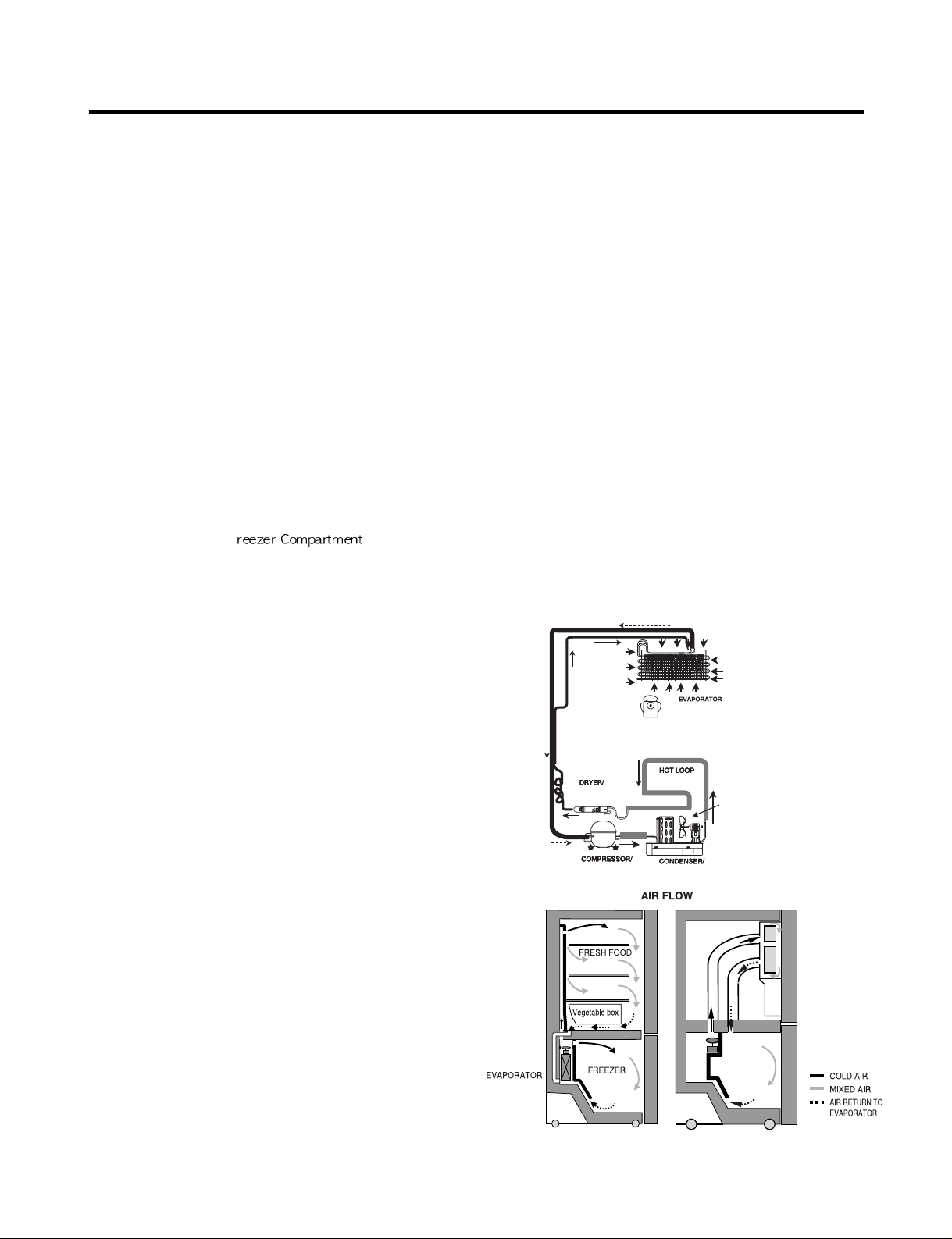
1-8 AIR FLOW / CIRCULATION D’AIR
EVAPORTOR FAN MOTOR
CONDENSER FAN MOTOR
ICE
ROOM
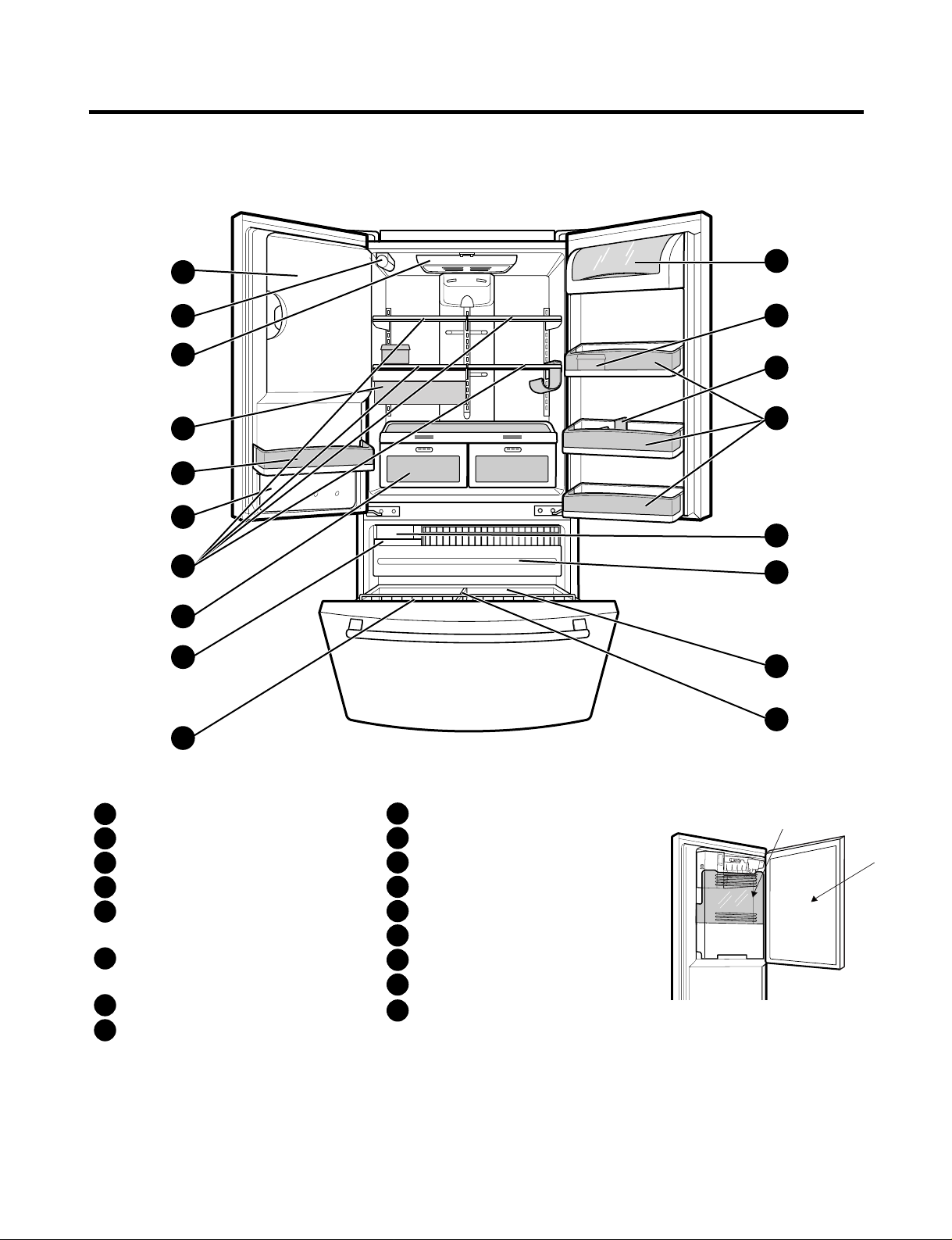
2. PARTS IDENTIFICATION
- 4 -
A
B
F
N
M
E
L
H
G
C
P
C
Q
O
D
I
K
J
Refrigerator Light
Filter (Inside)
Modular Door Bins
Refrigerator Shelves
Supra Fresh Crisper with
Tilt-Out Compartment
Ice Room
(ICEMAKER and ICE BIN)
Pull out Drawer
Turbo Motor
Tilt-Out Door Basket
Durabase
Divider
Ice Bin
Water Tank Cover
Snack Pan
Egg Box
Dairy Bin
Bottle Holder
A
B
C
D
E
F
G
H
I
J
K
L
M
N
O
P
Q
Ice Bank
Ice Door
3. OPERATION
- 5 -
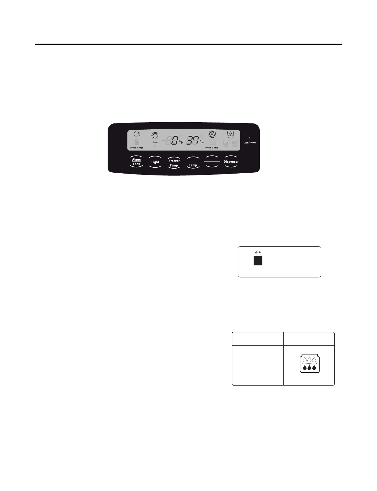
3-1. Explanation Of Each Function
1. Function
(1) When the appliance is plugged in, it is set to 37 °F for the refrigerator and 0 °F for the freezer.
You can adjust the refrigerator and the freezer control temperature by pressing the ADJUST button.
(2) When the power is initially applied or restored after a power failure, maintains its previously set temperature.
.
2 How to Toggle the Display between °F and °C
(1) The initial setting is °F and the display temperature mode can be changed from °F to °∆C or °∆C to °∆F by pressing and
holding the FRZ TEMP and the REF TEMP keys at the same time for over 5 seconds.
3. Lock function (dispenser and display button lock)
(1) When the refrigerator is first turned on, the buttons are not
locked. The display panel shows the padlock unlocked icon.
(2) To lock the display, the dispenser, and the control panel, press
and hold the LOCK button for 3 seconds. The locked pad lock
icon is displayed.
(3) The LOCK button is the only control feature that remains
active in the locked state. The buzzer sound, other control
buttons, and the dispenser are deactivated.
(4) To release from the locked state, press and hold the LOCK
button again for 3 seconds.
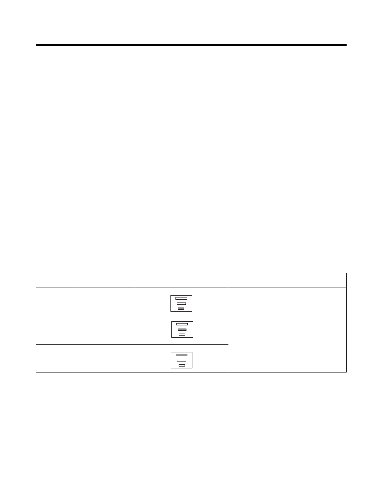
4. Filter condition display function
(1) There is a replacement indicator icon for the filter
cartridge on the dispenser.
(2)The water filter should be replaced approximately
every six months.
(3) The water filter icon will turn on every six months
to remind you to replace.
(4) After replacing the filter, press and hold the lock
button more than 3 seconds.
This will turn off the reminder icon and reset the timer.
Refrigerator
Ultra lce
Filter Reset
Ex) In selecting
"LOCK"
Ex) In selecting
"LOCK" again
Press & Hold Press & Hold
In initial Power On
/ Filter RESET
Replace indicator
light on
Classification
Filter Status
Display
Press & Hold Press & Hold
- 6 -
5. Ice Plus Selection
Please select this function for quick freezing.
(1) The ICE PLUS option starts counting its 24-hours period every time the
button is pressed.
(2) The ICE PLUS function automatically turns off after twenty-four hours pass.
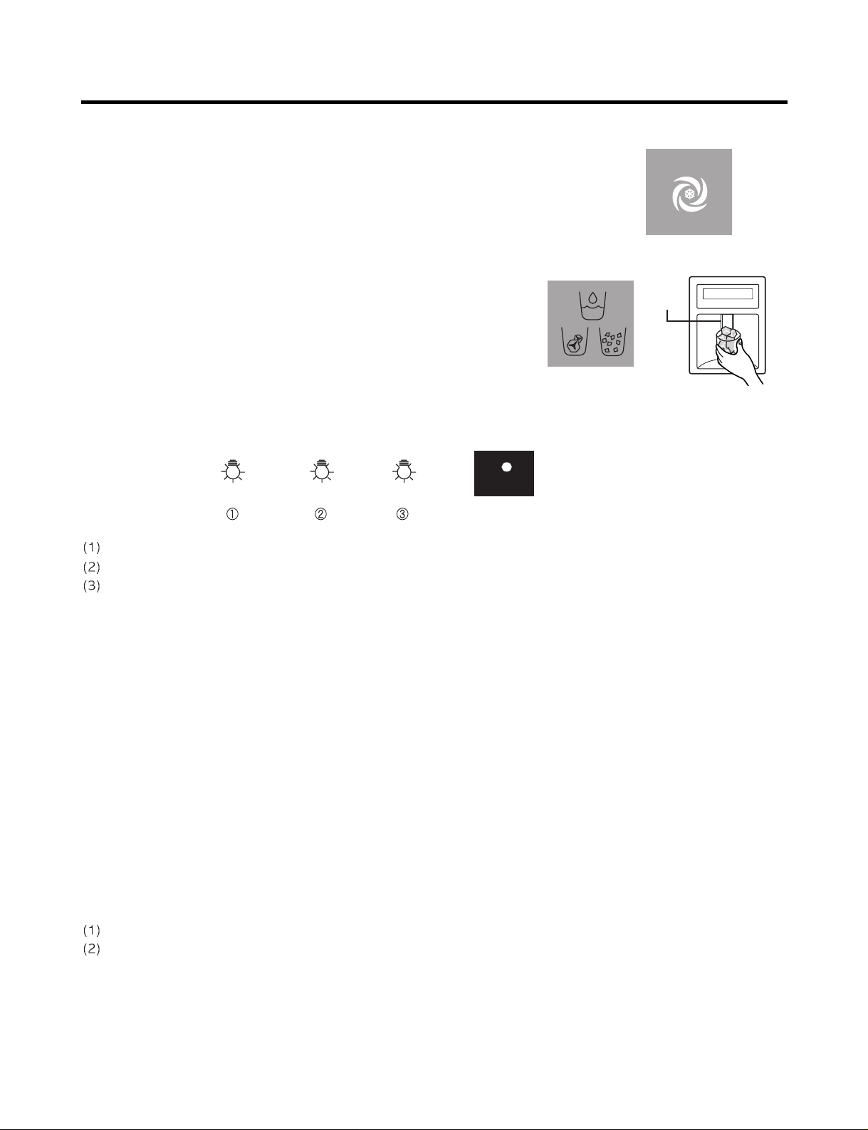
6. Dispenser Use Selection
You can select water or ice.
∗ Select water, crushed ice, or ice cubes by cycling through the
selections when pressing the DISPENSER button,
∗ Hold your cup in the dispenser for a few seconds after dispensing
ice or water to allow the last pieces of ice or drops of water to fall
into the cup.
7. Dispenser Light
Whenever the light button is pressed, the display changes as shown below.
Normal status: When dispenser is operated, DISPENSER LIGHT is ON.
AUTO status: Detecting the lighting of room by LIGHT SENSOR, DISPENSER LIGHT is on and off automatically .
ON status: DISPENSER LIGHT is on continuously.
8. Control Of Freezer Fan Motor
(1) Freezer fan motor has high and standard speeds.
(2) High speed is used at power-up, for Ice Plus, and when refrigerator is overloaded.
Standard speeds is used for general purposes.
(3) To improve cooling speed, the RPM of the freezer fan motor changes from normal speed to high.
(4) High speed (2700RPM) : Initial power on or load corresponding operation, Ice Plus
Normal speed (2400RPM) : General working conditions.
(5) Fan motor stops when a refrigerator or freezer door opens.
9. Cooling Fan Motor
(1) The cooling fan is switched ON and OFF in conjunction with the compressor.
(2) The cooling fan runs at a single speed.
(3) The Failure sensing method is the same as in the fan motor of the freezing fan motor(refer to failure diagnosis function
table for failure display).
10. Icing Fan
The Icing Fan is controlled by the the sensor on the top of the ice room.
The Failure sensing method is the same as in the fan motor of the freezer
(refer to failure diagnosis function table for failure display)
Pressing
Switch
Auto Auto
on
Light Sensor
- 7 -
11. Ice Plus
(1) The purpose of this function is to intensify the cooling speed of freezer and to increase the amount of ice.
(2) Whenever selection switch is pressed, selection/release, the LED will turn ON or OFF.
(3) If there is a power outage and the refrigerator is powered on again, Ice Plus will be canceled.
(4) To activate this function, press the Ice Plus key and the LED will turn ON. This function will remain activated for 24 hours.
The first three hours the compressor and Freezer Fan will be ON. The next 21 hours the freezer will be controlled at the
lowest temperature. After 24 hours or if the Ice Plus key is pressed again, the freezer will return to its previous
temperature.
(5) During the first 3 hours:
• Compressor and freezer fan (HIGH RPM) run continuously.
• If a defrost cycle begins during the first 90 minutes of Ice Plus, the Ice Plus cycle will complete its cycle after defrosting
has ended.
If the defrost cycle begins when Ice Plus has run for more than 90 minutes, Ice Plus will run for two hours after the
defrost is completed.
• If Ice Plus is pressed during defrost, Ice Plus LED is on but this function will start seven minutes after defrost is
completed and it shall operate for three hours.
• If Ice Plus is selected within seven minutes after compressor has stopped, the compressor (compressor delays seven
minutes) shall start after the balance of the delay time.
• The fan motor in the freezer compartment runs at high speed during Ice Plus.
(6) For the rest of the 21 hours, the freezer will be controlled at the lowest temperature.
12. Freezer and Refrigerator Lamp Auto Off
(1) To avoid heat damage caused by the lamp, it is turned off automatically when the refrigerator door is open for more than
7 minutes.
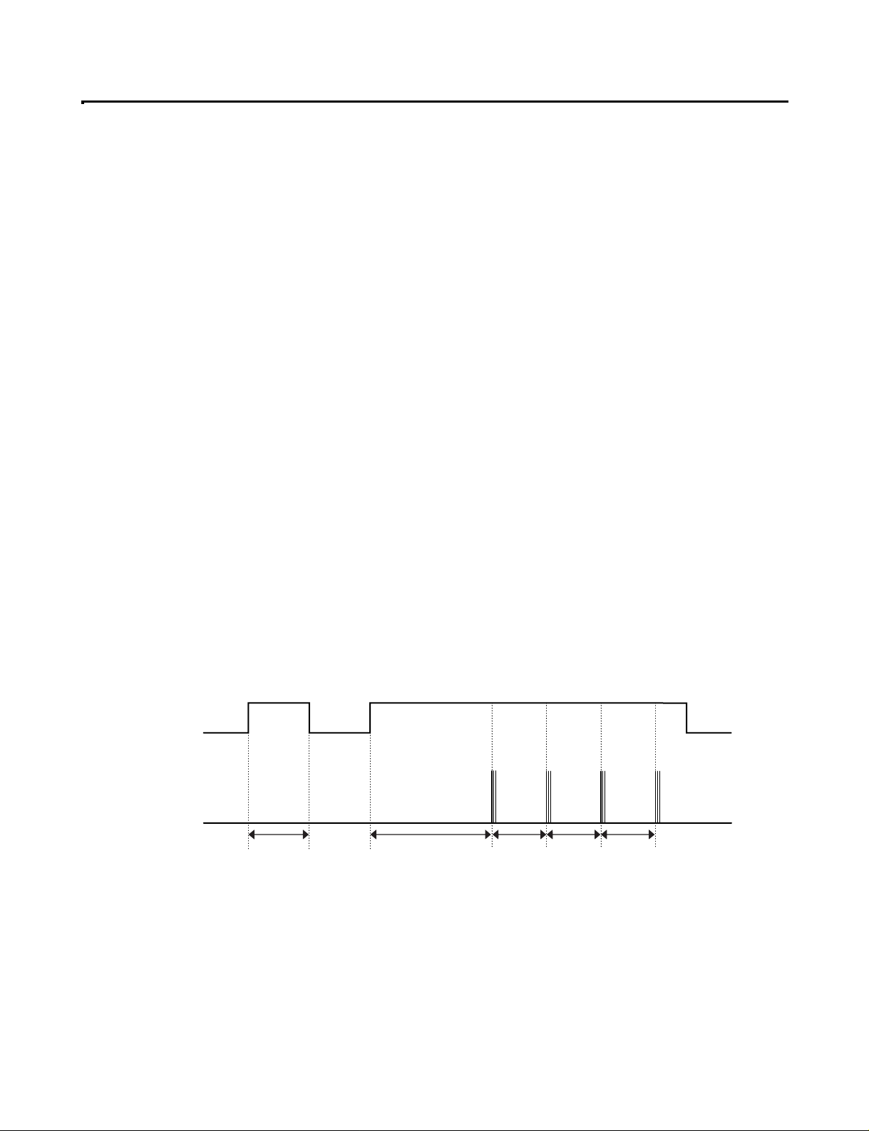
13. Alarm for Open Door
(1) This feature sounds a buzzer when the freezer or refrigerator door is not closed within 1 minute after it is opened.
(2 One minute after the door is opened, the buzzer sounds three times each for one half seconds. These tones repeat every
30 seconds.
(3) The alarm is cancelled when the freezer or the refrigerator is closed.
Closed Open Closed Open
3 Times 3 Times 3 Times 3 Times
Closed
Within 1 min. 1 min.
30 sec 30 sec 30 sec
Freezer Door
or Refrigerator
Door
Buzzer
- 8 -
14. Defrosting (removing frost)
(1) Defrosting starts each time the COMPRESSOR running time reaches 7 hours.
(2) For initial power on or for restoring power, defrosting starts when the compressor running time reaches 4 hours.
(3) Defrosting stops if the sensor temperature reaches 46.4°F (8°C) or more. If the sensor doesn’t reach 46.4°F (8°C) in
2 hours, the defrost mode is malfunctioning. (Refer to the defect diagnosis function, 15.)
(4) Defrosting won’t function if its sensor is defective (wires are cut or short circuited)
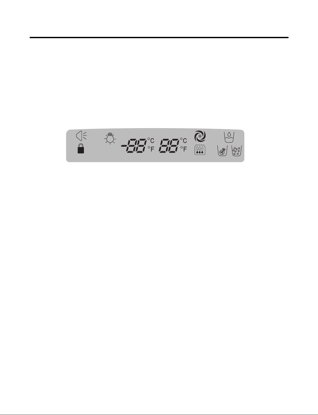
15. Defect Diagnosis Function
(1) Automatic diagnosis makes servicing the refrigerator easy.
(2) When a defect occurs, the buttons will not operate; but the tones will sound.
(3) When the defect CODE removes the sign, it returns to normal operation (RESET).
(4 The defect CODE shows on the Refrigerator and Freezer Display.
✽ LED check function: Press Ice Plus and Freezer buttons for a second, display LED graphics on.
If releasing the button, the LED graphic displays the previous status.
Press & Hold Press & Hold
Auto
on
- 9 -
3-2. Ice Maker Function
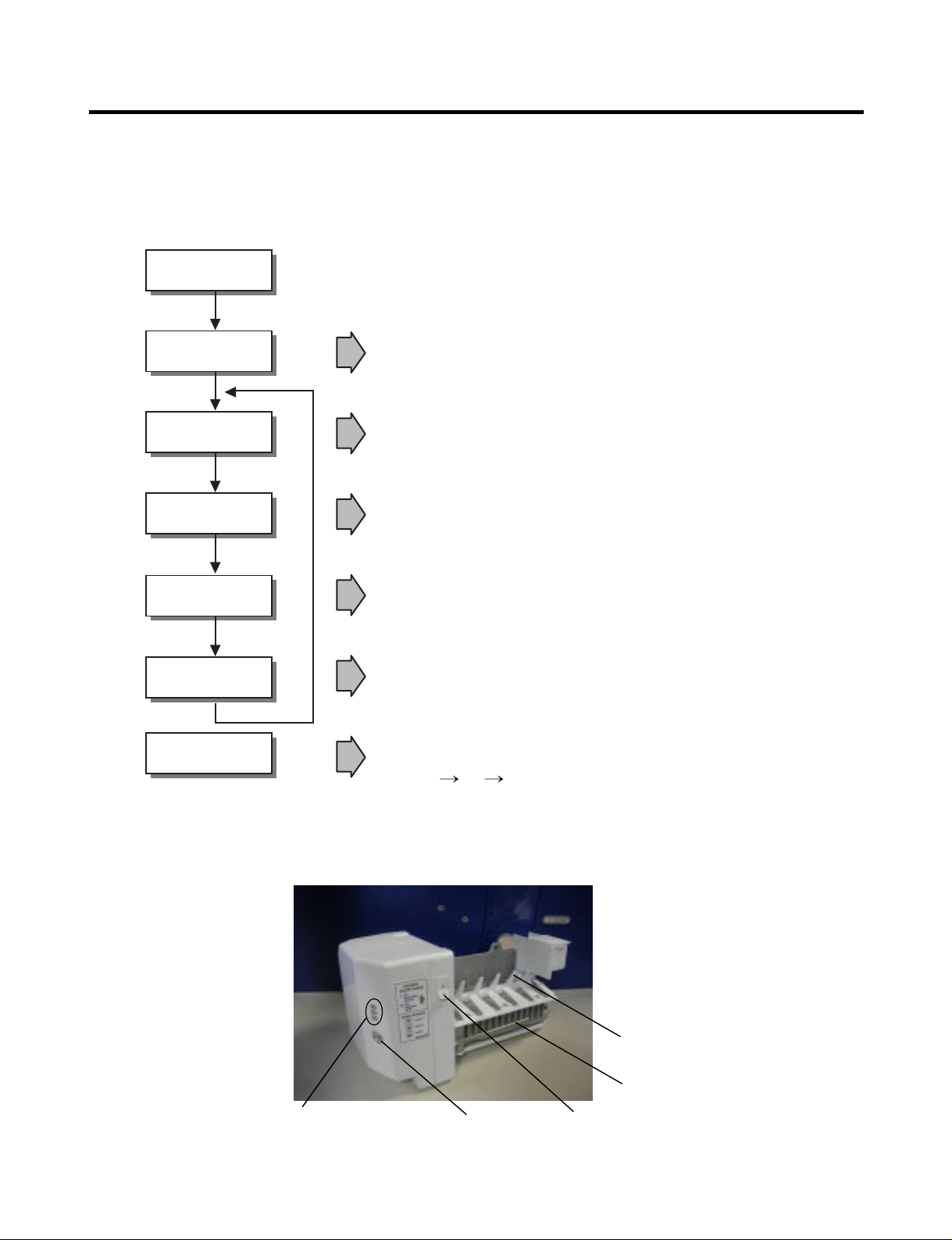
1. Operation Principle of icemaker
(1) Turning the Icemaker stop switch off (O) stops the ice making function.
(2) Setting the Icemaker switch to OFF and then turning it back on will reset the icemaker control.
• Adjusts EJECTOR to Start Position with power on.
Power On
Start Position
Icemaking
Mode
Harvest
Mode
Fill
Park Position
Test Mode
• Waits until water becomes ICE after starting the
icemaking operation.
• Runs MOTOR to drop ice from the tray into the ICE BIN.
(During harvest mode, check if the ice bin is full.)
• Performs Ice Making Mode after supplying water by operating
the SOLENOID in ICE VALVE.
• To operate LINE and SERVICE, press and hold the Cube Size button
for 3 seconds. The icemaker will run through 3 stages:
Harvest Fill Icemaking.
• Reaches Start Position
Cube Size
Indicator Light
Cube Size
Selection Button
Power
Switch
Automatic
Shut off Arm
EJECTOR
- 10 -
2. Icemaking Mode
(1) Icemaking refers to the freezing of supplied water in the ice tray. Complete freezing is assured by
measuring the temperature of the tray with Icemaking SENSOR.
(2) Icemaking starts after completion of the water fill operation.
(3) The icemaking function is completed when the sensor reaches 1 9 °∆F (-7 °∆C), 55 minutes after starting.
NOTE : After the icemaker power is ON, the icemaker heater will be on for test for 6 seconds.
3. Harvest Mode
(1) Harvest (Ice removing) refers to the operation of dropping cubes into the ice bin from the tray when
icemaking has completed.
(2) Harvest mode:
• The Heater is ON for 30 seconds, then the motor starts.
• The feeler arm senses the quantity of ice in the ice storage bin while rotating with the EJECTOR.
A. Ice storage bin is full : The EJECTOR stops (heater off).
B. Ice storage bin is not full : The EJECTOR rotates twice to open for ice.
* If the EJECTOR does not rotate once within 5 minutes in B mode, separate heater control mode starts operating to
prevent the EJECTOR from being constrained. (It is recommended that the user open for ice to return to normal mode.)
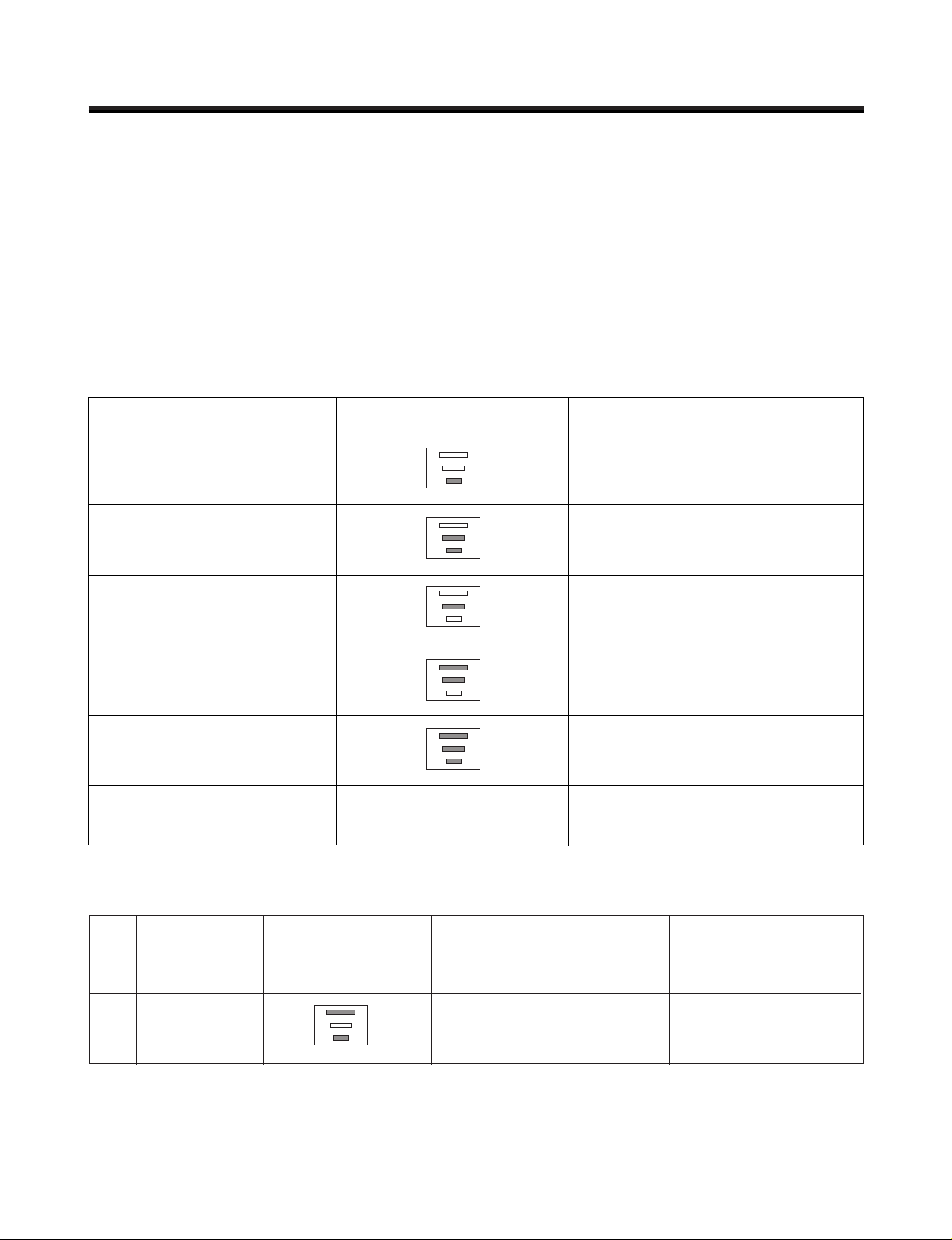
4. Fill/Park Position
(1) Once a normal harvest mode has been completed, the water solenoid will be activated.
(2) The amount of water is adjusted by pressing the fill key repeatedly. This changes the time allowed for fill as illustrated in
the table below.
Water supply amount TABLE
ST AGE TIME TO SUPPL Y INDICA TIONS REMARKS
1
2
3
5 sec.
5.5 sec.
(FIRST STAGE)
6 sec.
The water amount will vary depending
on the water control switch setting as
well as the water pressure of the
connected water line.
- 11 -
5. Function TEST
(1) This is a forced operation for test, service, cleaning, etc. It is operated by pressing and holding the cube size button for 3
seconds.
(2) The test works only in the Icemaking Mode. It cannot be entered from the Harvest or Fill mode.
(3) Caution! Caution! Caution! Caution! If the test is performed before water in the icemaker is frozen, the ejector will pass
through the water. When the fill mode begins (Stage 4), unless the water supply has been shut off, added water will
overflow into the ice bin. If the control doesn ’ t
(4) After water is supplied, the normal CYCLE is followed: icemaking → Harvest → Park Position → Fill.
(5) Five seconds after Stage 5 is completed, the icemaker returns to MICOM control. The time needed to supply water
resets to the
Diagnosis TABLE
6. Error codes shown on the icemaker water supply control panel
STAGE ITEMS INDICATOR REMARKS
1
2
3
4
5
6
HEATER
MOTOR
HALL IC I
HALL IC II
VALVE
Reset
Five seconds after the heater starts, it
will go off if the temperature by
sensor is higher than 10°C
Five seconds after the heater starts, you
can confirm that the motor is moving.
Check whether ice bin is full. If the ice bin
if full, the motor and heater are off, but on
standby until the ice bin is empty.
You can confirm HALL IC detection of start
position.
Two seconds after the detection of start
position, you can confirm that the valve is on.
Five seconds after the fifth stage is
completed, the icemaker resets to initial
status.
Return to Status prior to
TEST MODE
NO DIVISION INDICATOR CONTENTS REMARKS
1
2
Normal
Icemaking
sensor
malfunction
Mark time to
supply
None
Open or short-circuited wire
Display switch
operates properly
Make sure that the wire
on each sensor is
connected.
- 12 -
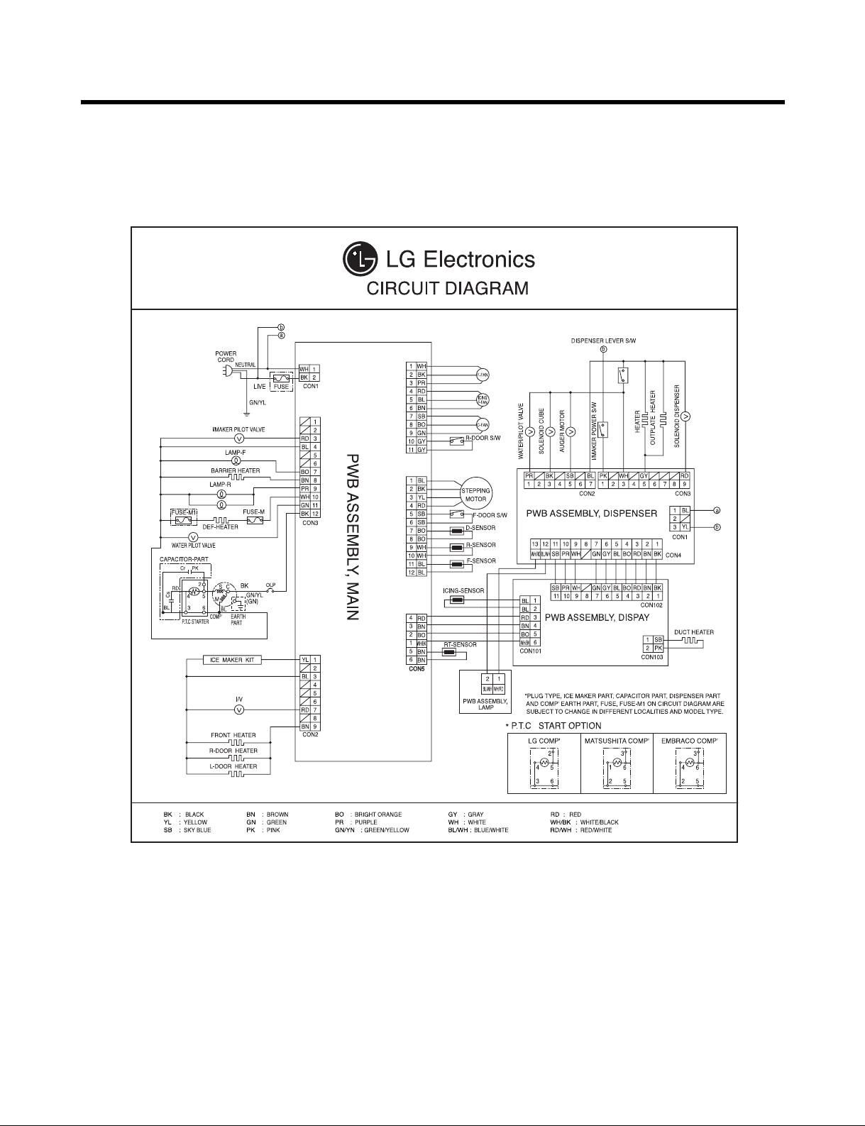
4. WIRING DIAGRAM

5-1. Compressor
1. Role
The compressor intakes low temperature and low pressure gas from the evaporator of the refrigerator and
compresses this gas to high-temperature and high-pressure gas. It then delivers the gas to the condenser.
2. Composition
The compressor includes overload protection. The PTC starter and OLP (overload protector) are attached to
the outside of the compressor. Since the compressor is manufactured to tolerances of 1 micron and is
hermetically sealed in a dust and moisture-free environment, use extreme caution when performing repairs.
3. Note for usage
(1) Be careful not to allow over-voltage and over-current.
(2) If compressor is dropped or handled carelessly, poor operation and noise may result.
(3) Use proper electric components appropriate to the particular compressor in your product.
(4) Keep the compressor dry. If the Compressor gets wet (in the rain or a damp environment) and rust forms
in the pin of the Hermetic Terminal, poor operation and contact may result.
(5) When replacing the compressor, be careful that dust, humidity, and soldering flux don’t contaminate the
inside of the compressor. Dust, humidity, and solder flux may contaminate the cylinder and may cause
noise, improper operation, or even lock up.
5. ADJUSTMENT
- 13 -
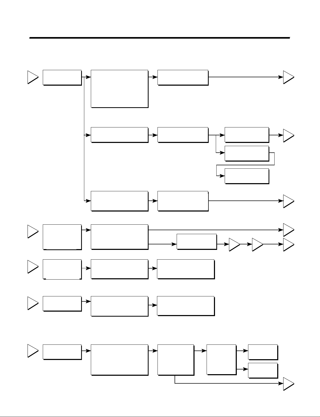
4. diagnosis
- 14 -
1
2
3
4
5
2
5
5
3
5
1
43
YES
NO
YES
The range of resistance is between 1~50Ω(ok)
Open or short
YES YES
NO
NO
Power Source.
No Voltage.
(Rated Voltage
±10%)?
Replace OLP.
Reconnect.
Reference 5-2
Reference 5-3
Did
compressor
start?
Compressor
is OK
Replace the
compressor
Check connection
condition.
OLP disconnected?
Advise customer that
power supply needs to be
checked by an electrician.
Replace
Compressor.
Supply
voltage rating
with ±10%.
Applied voltage isn't
in acceptable range.
(115V ±10%)
Remove PTC-Starter
from Compressor and
measure voltage
between Terminal C of
Compressor and
Terminal 5 or 6 of PTC.
Check resistance
between M-C, S-C and
M-S in Motor
Compressor.
Check resistance of
two terminals in
PTC-Starter.
Check resistance of two
terminals in OLP.
Check the power supply
under load.
(Compressor attempting
to re-start after being off
for 5 minutes).
Check
resistance of
Motor
Compressor.
Check
resistance of
PTC-Starter.
Check OLP.
Check
starting state.
- 15 -
5-2. Positive Temperature Coefficient (PTC) – Starter
1. Composition
(1) PTC (Positive Temperature Coefficient) is a no-contact semiconductor starting device which uses ceramic
material consisting of BaTiO3.
(2) The higher the temperature is, the higher the resistance value. These features are used as a starting
device for the motor.
2. Role
(1) The PTC is attached to the sealed compressor and is used for starting the compressor motor.
(2) The compressor is a single-phase induction motor. For starting operation, the PTC allows current flow to
both the start winding and main winding.
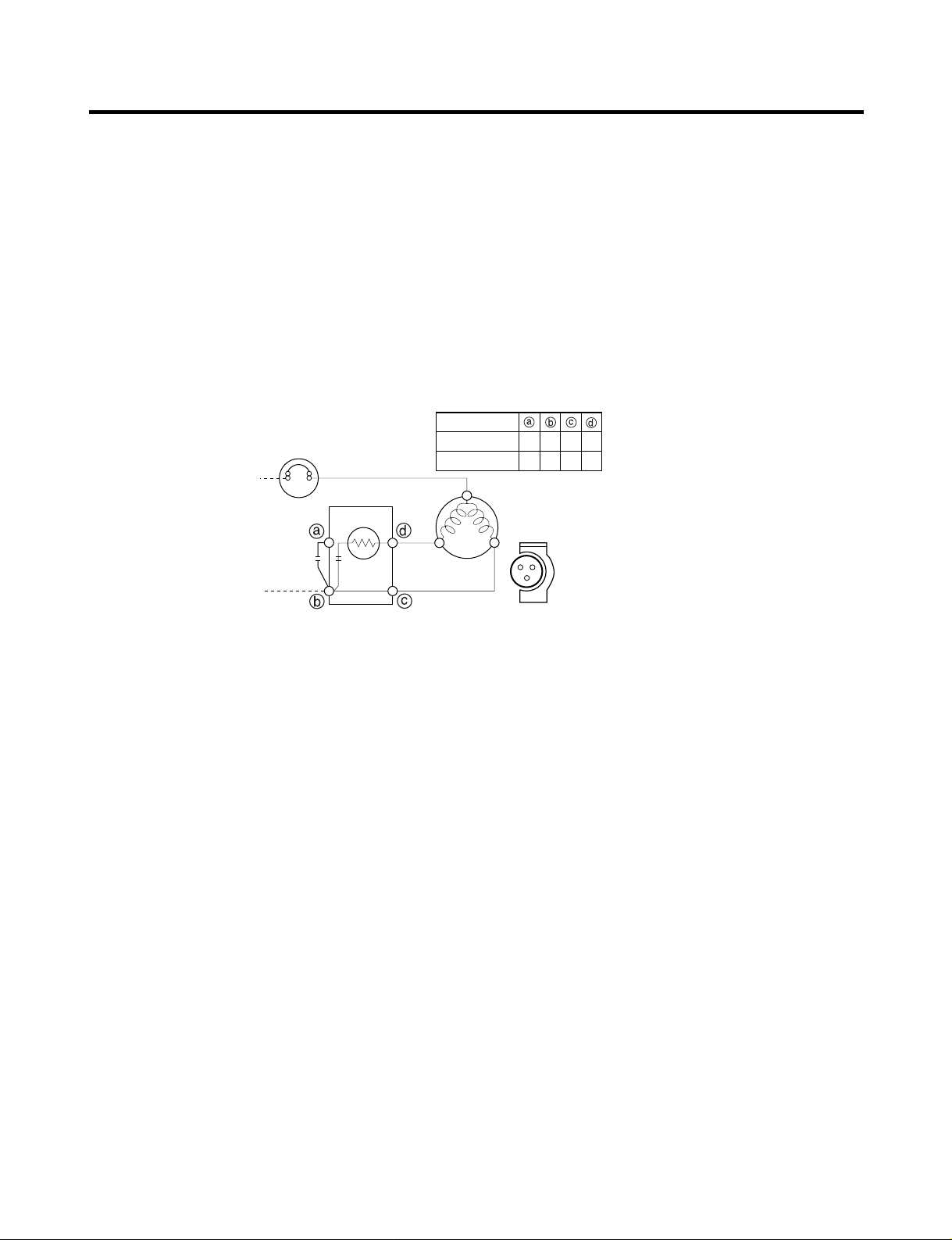
3. PTC – Applied circuit diagram
● Starting Method for the Motor
4. Motor restarting and PTC cooling
(1) It requires approximately 5 minutes for the pressure to equalize before the compressor can restart.
(2) The PTC device generates heat during operation. Therefore, it must be allowed to cool before the
compressor can restart.
5. Relation of PTC – Starter and OLP
(1) If the compressor attempts to restart before the PTC device is cooled, the PTC device will allow current to
flow only to the main winding.
(2) The OLP will open because of the over current condition. This same process will continue (3 to 5 times)
when the compressor attempts to restart until the PTC device has cooled. The correct OLP must be
properly attached to prevent damage to the compressor. Parts may appear physically identical but could
have different electrical ratings. Replace parts by part number and model number. Use only approved
substitute parts.
6. Note for Using the PTC-Starter
(1) Be careful not to allow over-voltage and over-current.
(2) Do not drop or handle carelessly.
(3) Keep away from any liquid. If liquid such as oil or water enters the PTC, the materials may fail due to
breakdown of their insulating capabilities.
(4) If the exterior of the PTC is damaged, the resistance value may be altered. This can cause damage to the
compressor and result in a no-start or hard-to-start condition.
(5) Always use the PTC designed for the compressor and make sure it is properly attached to the compressor.
Parts may appear physically identical but could have different electrical ratings. Replace parts by part
number and model number. Use only approved substitute parts.
PTC STARTER
SEALED
TERMINAL
COMPRESSOR
MOTOR
C
M
S
M
S
N
L1
OVERLOAD PROTECTOR
Resistance Starter Capacitor Running
PTC
2
LFX21960**
LFX25960**
3 2 5 6
2 3 6 5
- 16 -
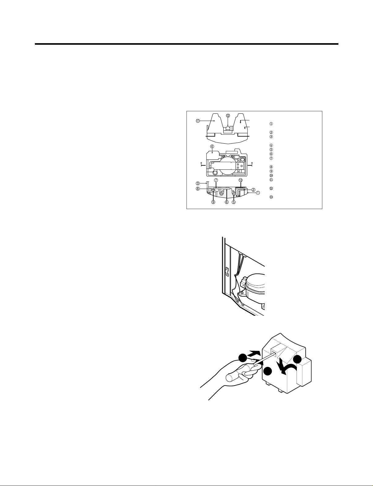
5-3. Over Load Protector (OLP)
1. Define
(1) The OLP (OVERLOAD PROTECTOR) is attached to the Compressor and protects the motor by opening the
circuit to the motor if the temperature rises and activating the bimetal spring in the OLP.
(2) When high current flows to the compressor motor, the Bimetal works by heating the heater inside the OLP,
and the OLP protects the Motor by cutting off the current flowing to the Compressor Motor.
2. Role
(1) The OLP is attached to the sealed compressor
used for the refrigerator. It prevents the motor
coil from being started in the compressor.
(2) For normal operation of the OLP, do not turn
the adjustment screw of the OLP in any way.
5-4. Remove the cover Positive Temperature Coefficient (PTC)
(1) Remove the cover of the mechanical area.
(2) Disconnect the two clamps holding
the compressor in place.
(3) Loosen two screws on compressor base.
(4) Use a screwdriver to pry off the cover.
(5) Assembly is the reverse order of disassembly.
Part
Customer part
number
Lot code/
date code
330 FBYY -S1 BOX98
12345678
Physical
termination
part number
Electrical
characteristics
part number
No. Name
Base, phenolic
(UL 94 V-0 rated)
Movable arm support, plated steel
Stationary contact support,
plated steel
Heater support, plated steel
Heater, resistance alloy
Disc, thermostatic alloy
Movable arm, spring temper
copper alloy
Contact, movable, silver on copper
Contact, stationary, silver on copper
Slug, plated steel
Cover, polyester
(UL 94 V -0 rated)
Pin connector, plated copper alloy
(To engage 2.33/2.66 mm dia. pin)
Quick-connect terminal, brass,
conforms to UL 310, MEMA
DC-2, DIN 46344
(OVERLOAD PROTECTOR cross section)
2
3
1
- 17 -
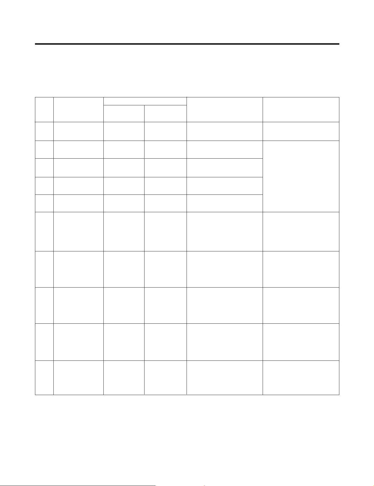
6-1. Error Code Summary
ww
WARNING : When you check the Resistance values, be sure to turn off the power.
And wait for the voltage-discharge sufficiently.
6. TROUBLESHOOTING
1
2
3
4
5
6
7
8
9
10
Normality
Freezer Sensor
Error
Refrigerator
Sensor Error
Defrosting
Sensor Error
Icing Sensor
Error
Poor Defrosting
Abnormality of
BLDC FAN Motor
for Ice Making
Abnormality of
BLDC FAN Motor
for Freezer
Abnormality of
BLDC FAN Motor
for Mechanic Room
Communication
Error
None
Short or Disconnection
of Freezer Sensor
Short or Disconnection
of Refrigerator Sensor
Short or Disconnection
of Defrosting Sensor
Short or Disconnection
of Icing Sensor
Even though it is passed
1 hour since then
Defrosting , if Defrosting
sensor is not over 8°C, it
is caused
It is caused when
feedback signal isn’ t
over 115
seconds during BLDC
FAN motor operating
It is caused when
feedback
signal isn ’ t over 115
seconds during BLDC
FAN motor operating
Communication Error
between Micom of Main
PCB and Display Micom
It is caused when
feedback
signal isn’ t over 115
seconds during BLDC
FAN motor operating
Normal operation of Display
Check each sensor and its
connector.
Temperature Fuse
Disconnection, Heater
disconnection, DRAIN Jam,
Poor Relay for Heater
Poor BLDC Motor
connection, DRIVE IC, and
TR Tx/Rx between icemaker
and main board.
Poor BLDC Motor
connection, DRIVE IC, and
TR Tx/Rx between icemaker
and main board.
Poor BLDC Motor
connection, DRIVE IC, and
TR Tx/Rx between icemaker
and main board.
Poor Communication
connection,Poor TR of
Transmitter and Receiver
Tx/Rx between icemaker
and main board.
Er
Er
Er
Er
Er
Er
Er
Er
Er
FS
rS
dS
IS
dH
IF
FF
CF
CO
NO
Error Detection
Category
Error Generation Factors Remark
Freezer
Temperature
Ref.
Temperature
Error Display
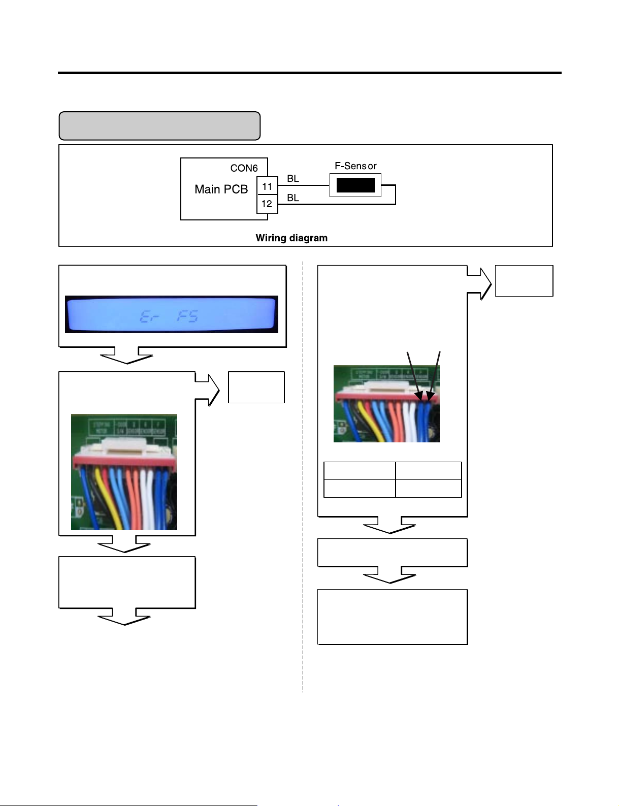
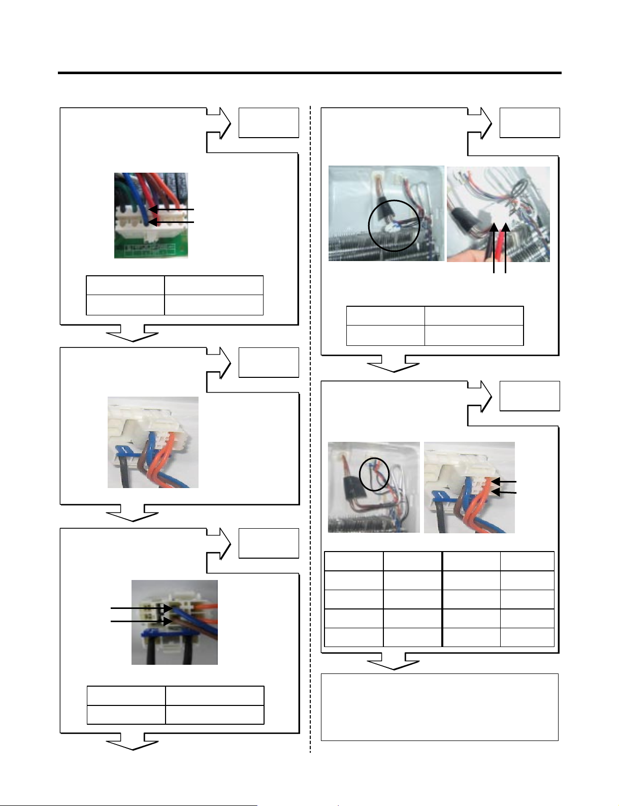
6-2. Troubleshooting With Error
- 18 -
Is Er-FS dis played?
Disconnect CON6 and measure
the value. Is resistance value
between pins 11 & 12 of CON6
as below? (BL to BL)
Freezer Sensor Err or
Is the connection loose?
If the ER-FS appears, Replace
the main PCB. Otherwise,
explain to the customer!
Replace
F-sensor
pin12
pin11
1.4 ~ 120k‰pin11 to pin12
ResultTest Point
Reconnect
Reconnect CON6 and Power ON
Power Off
Tip : To protection of MICOM
Yes
Yes
No
No
No
- 19 -
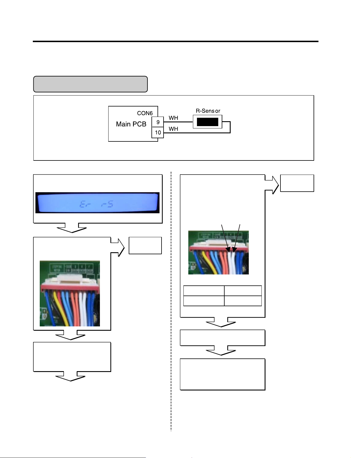
Refrigerator Sensor Error
Is Er-rS displayed?
Disconnect CON6 and measure
the value. Is resistance value
between pins 9 & 10 of CON6 as
below? (WH to WH)
Yes
Is the connection loose?
If the ER-rS appears, Replace
the main PCB. Otherwise,
explain to the customer!
Replace
R-sensor
No
pin10
pin9
Yes
6 ~ 300 k‰pin9 to pin10
ResultTpin10 pin9
Reconnect
Reconnect CON6 and Power ON
Power Off
Tip : To protection of MICOM
No
No
Wiring dia gram
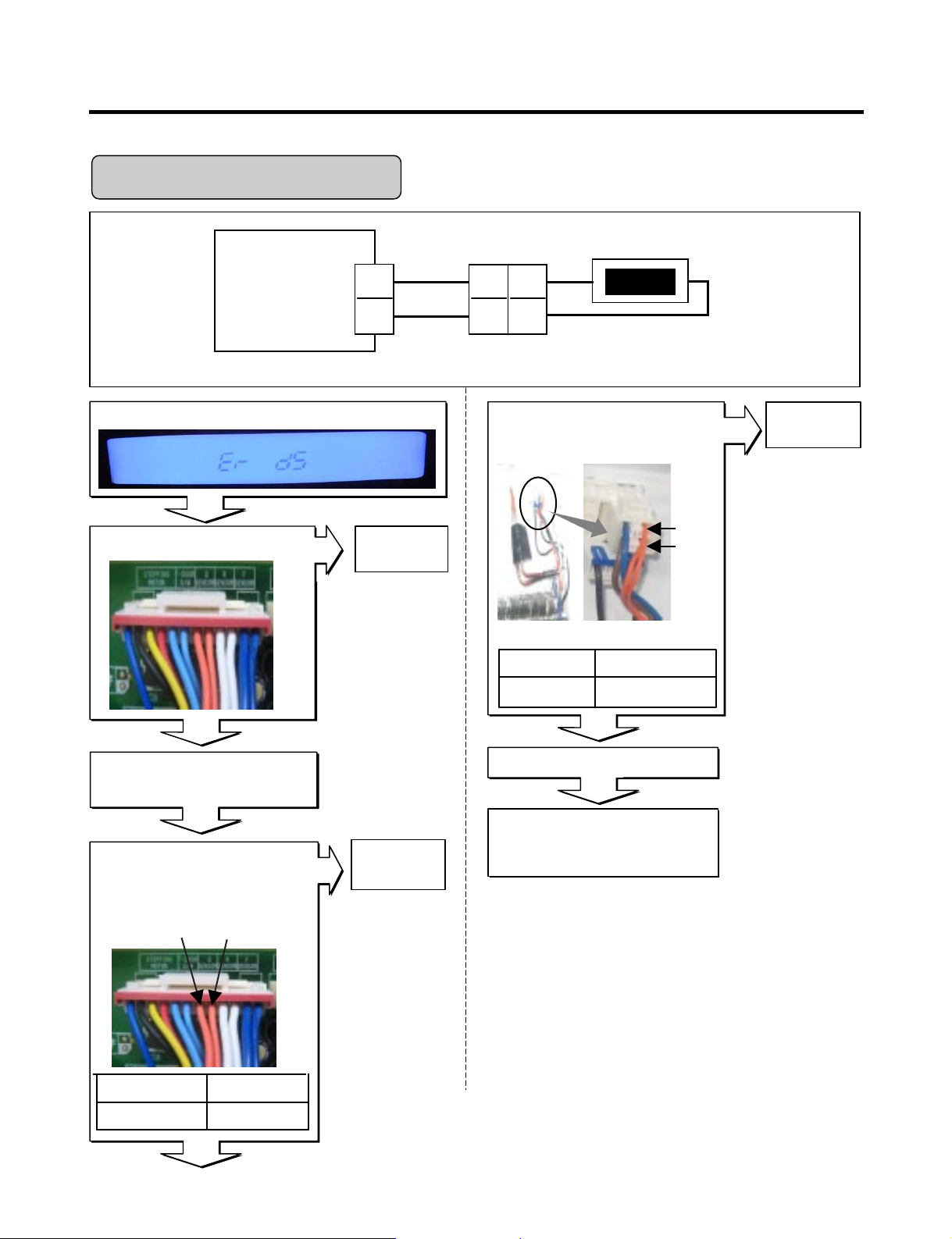
- 20 -
Housing-A
Main PCB
BO
BO
BO
BO
D-Sensor
7
8
2
1
CON6
7
6
Defrost Sensor Error
Wiring dia gram
Is Er-dS displayed?
Disconnect CON6 and measure
the value. Is resistance value
between pins 7 & 8 of CON6 as
below? (BO to BO)
Yes
Is the connection loose?
If the ER-dS appears, Replace
the main PCB. Otherwise,
explain to the customer!
Replace
D-sensor
No
No
No
pin8
pin7
6 ~ 300k‰Pin7 to pin8
ResultTest Point
Reconnect
Reconnect and Power ON
Power Off
Tip : To protection of MICOM
Is resistance value between
pins 1 & 2 of Housing- A as
below? (BO to BO)
Replace a
D-Sensor
pin1
pin2
1.156 ~141.5k‰Pin1 To pin2
ResultTest Point
Checking Open or Short of wire
Yes
Yes
No
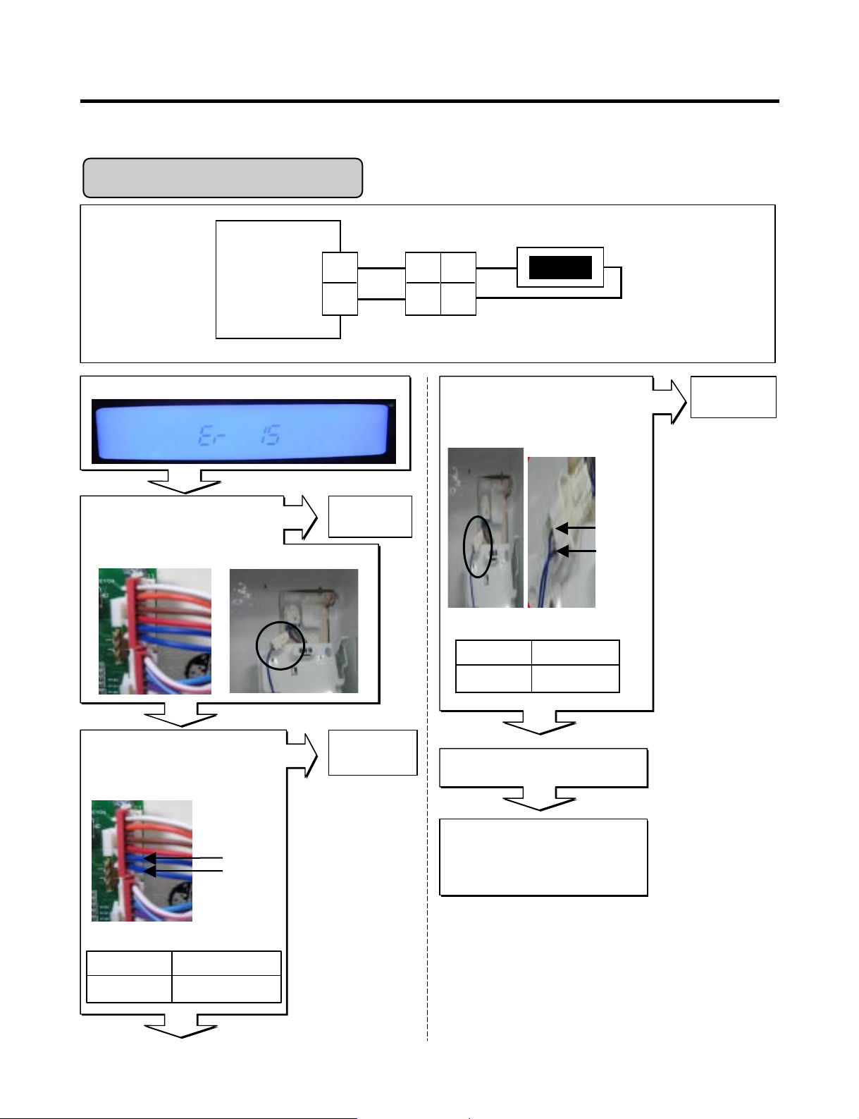
- 21 -
Is Er-IS displayed?
Yes
Yes
Yes
No
No
Yes
Housing-A
Display
PCB
BL
BL
BL
BL
Icing-Sensor
CON101
1
2
1
2
1
2
Is the connection loose?
Reconnect
pin1 BL
pin2 BL
Icing Room Sensor Error
1.156 ~141.5k‰pin1 to pin2
ResultTest Point
Icing room Sensor Resistance
Replace the
Icing-Sensor
(1) To (2)
Test Point Result
1.4 ~120k‰
Checking Open or Short of wire
pin2 BL
pin1 BL
Replace
Main PCB
If the ER-IS appears,
Replace Main PCB
Otherwise, explain
to the customer!
Reconnect and Power ON
Display PCB Inner of Icing door
Is resistance value between
pins 1 & 2 of Housing- A as
below? (BL to BL)
No
Disconnect CON101 and
measure the value. Is resistance
value between pins 1 & 2 of
CON101 as below? (BL to BL)
Wiring diagram
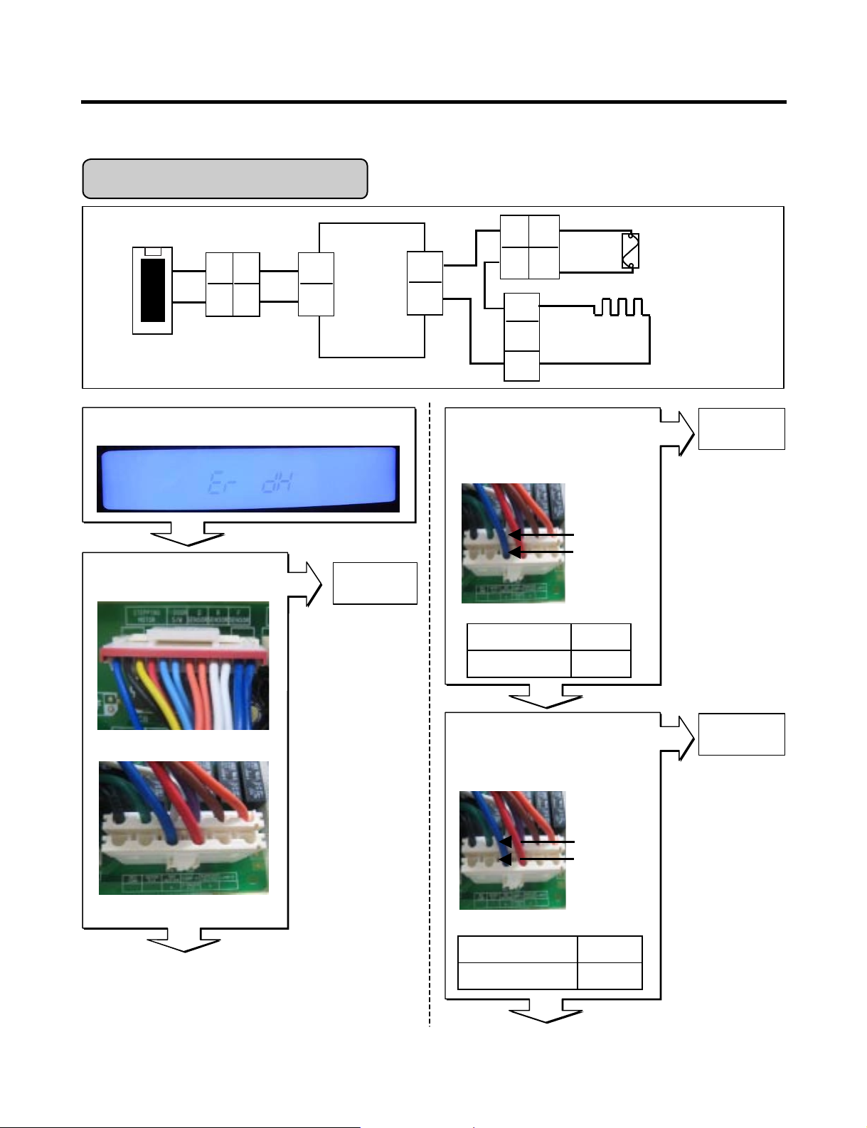
- 22 -
Enter the TEST 3 MODE
Is the voltage value
between pins 10 (WH) and
4 (BL) of CON3 115 V AC?
Is Er-dH displayed?
Yes
Yes
Yes
No
Yes
Yes
No
CON6
CON3
Replace
MAIN PCB
Replace
MAIN PWB
Main
PCB
WH
BL
FUSE-M
CON3
10
4
DEF-Heater
Housing-A
BO
D-Sensor
7
8
BO
2
CON6
BO
BO
7
6
BL
BN
BK
2
1
7
6
1
3
1
2
BK
Is the connec tion loose?
pin4 BL
pin10 WH
pin4 BL
pin10 WH
115Vpin4 To pin 10
ResultTest Point
Reset TEST3 MODE(Normal)
Is the voltage value between
pins 10 (WH) and 4 (BL) of
CON3 for 0 V AC?
0 ~ 2 V
Reset/Norm op
ResultTest Point
Defrost Heater Error
Wiring dia gram
Relay Open
Reconnect
Relay operation
- 23 -
Explain to the customer! :
It can be occurred, when the gasket is not
stuck to product or when you put the high
temperature loads (hot foods) a lot
in the product.
Normal
Is the resistance value
between pins 10(WH)
And 4(BL) of CON3
like as below?
Replace
DEF-sensor
Yes
Yes
Yes
Yes
Yes
No
No
No
No
No
Is the resistance value of
heater like as below?
(2)
(1)
Replace
Heater
Test Point Result Test Point Result
-30°C 129.3 kΩ 10°C 19.53 kΩ
-20°C 76.96 kΩ 20°C 13.03 kΩ
-10°C 47.34 kΩ 30°C 8.896 kΩ
0°C 30 kΩ 40°C 6.201 kΩ
(2) BO
(1) BO
Heater Resistance
Defrost Sensor Resistance
Is the resistance
value of DEF-sensor like
as below? It depends on
the temperature.
Replace
Fuse-M
Is the resistance value
of Fuse –M like
as below?
(2) BN
(1) BL
Open or Short of Fuse-M
pin4 BL
pin10 WH
34 ~ 42 Ω (1) To (2)
RessultTest Point
34 ~ 42 Ω (1) To (2)
RessultTest Point
0 Ω (1) To (2)
RessultTest Point
Resistance
Is the connection loose?
Reconnect
- 24 -
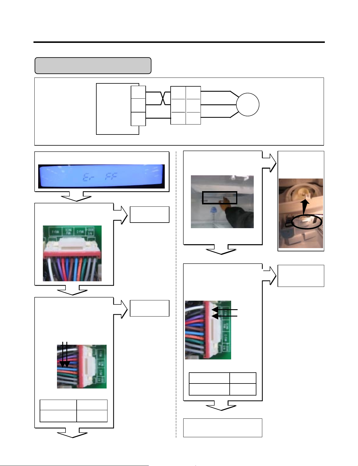
Is Er-FF displayed?
Yes
Yes
Yes
Yes
Yes
Is the connection loose?
Reconnect
Housing
Main
PCB
WH
CON4
1
2
3
1
2
3
BK
PR
F-FAN
1
2
3
BK
RD
PR
Check fan motor
(Connector,
Frozen,Locked)
Is the feedback voltage
between pin2 and pin3 of
CON4 like as below?
(from motor to main board)
No
No
No
No
Wiring diagram
Feedback Voltages
Replace
Main PCB
Replace
Main PCB
Pin1 WH
Pin2 BK
Pin3 PR
Pin2 BK
Freezer Fan Voltages
Reset and
Enter the TEST 1 MODE
Is the output voltage between
pin1 and pin2 of
CON4 like as below?
Does the cold-air come out
of the top of the main duct?
Explain to the customer!
Freezer Fan Error
12 ~ 16 V
pin1 to pin2
RessultTest Point
RessultTest Point
1 ~ 4 Vpin2 to pin3
 Loading...