

Page 1
Installation Instructions
n
h
year
with Kit N
Ori
fic
e s
ize
: 5
5
Inp
ing
(Btu/
hr)
:
Natural Gas Dyer to LP Conversion Kit
WARNING
This conversion kit shall be installed by a qualifi ed service agency
in accordance with the manufacturer’s instructions and all applicable codes and requirements of the authority having jurisdiction.
The information in these instructions must be followed to minimize the risk of fi re or explosion or to prevent property damage,
personal injury or death. The qualifi ed service agency is responsible for the proper installation of this kit. The installation is not
proper and complete until the operation of the converted appliance is checked as specifi ed in the manufacturer’s instructions
supplied with the kit.
WARNING
Failure to comply with the following proper instructions and use of correct conversion kit can
result in fi re, explosion, serious bodily injury and/or property damage.
and the responsibility of the person making the conversion and shall be made by a QUALIFIED SERVICE TECHNICIAN ONLY. USE ONLY THE CONVERSION KIT SPECIFIED IN THE PARTS CATALOG
FOR THE MODEL NUMBER OF THE DRYER BEING CONVERTED.
IMPORTANT
This kit was designed to be used with bottled gas (tanks). The gas line must be equipped with •
a gas pressure regulator that provides gas between 8 inches (20 cm) water column maximum
and 11 inches (28 cm) water column minimum at the connection to the dryer.
This kit is approved for use on dryers manufactured on or after July 1, 2008, having burners •
with a gas valve showing part no. 13118070 or 145493-000.
If installing this conversion kit on valve no. 13118070, input rating will be 22,000 BTU’s/hour. If •
installing this conversion kit on valve no. 145493-000, input rating will be 20,000 BTU’s/hour.
BTU rating refers to heat input at sea level. For operation at elevations above 2,000 feet, the •
BTU input rating should be reduced at the rate of 4 percent for each 1,000 feet above sea level.
Observe all local codes and American National Standard National Fuel Gas Code ANSI Z •
223.1-1988. Contact the tank gas dealer for any questions about installation.
THE CONVERSION SHALL BE CARRIED OUT IN ACCORDANCE WITH THE REQUIREMENTS •
OF THE PROVINCIAL AUTHORITIES HAVING JURISDICTION AND IN ACCORDANCE WITH
THE REQUIREMENTS OF THE CSA B149.1, INSTALLATION CODE.
Refer to the product Installation Instructions for gas supply line connections to the dryer.•
Conversion is at the risk of
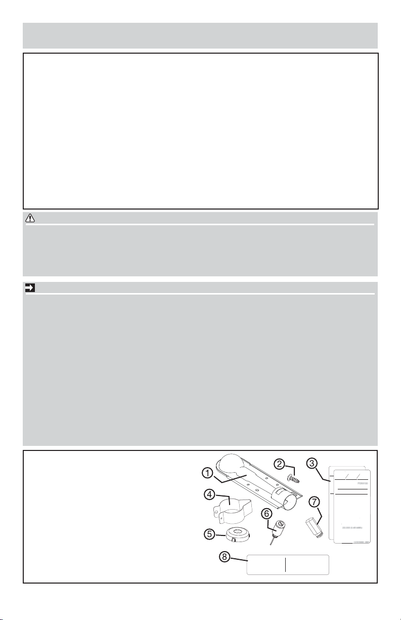
Kit Components:
Stainless steel burner tube1.
Screw, #8 (18x.375)2.
Converted rating plate (English)3.
Converted rating plate (French)
Adjustable shutter4.
Alignment collar5.
Blocking pin6.
LP orifi ce (stamped “55”)7.
Control conversion label8.
Cette sécheuse a été convertie le
This dryer was field converted on
was field converted o
année mois jour
day
month
year
mont
pour fonctionner au gaz LP à l’aide
de la trousse no PCK4100
to LP gas with Kit No.
o.
par
by
(nom et adresse de l’organisme qui
(name and address of organization
a effectué la conversion), qui
making this conversion), who
accepte l’entière resonsabilité de la
accepts the responibility for the
qualité de la conversion.
correctness of this conversion.
Pression à la tubulure
Manifold pressure (”wc):
d’alimentation (”wc):
7” - 10”
7” - 10”
Orifice size: 55
Injecteur numéro: 55
55
55
55
55
This control has
been converted for
use with LP gas.
Cette sécheuse a été
convertie pour
fonctionner au gaz LP.
137070500 0807
1
ut rat
Input rating (Btu/hr):
Debit calorifique (Btu/hr):
55
55
22,000 (6.45 kWh)
55
55
137070401 0807
137066200 B (0808)
Page 2
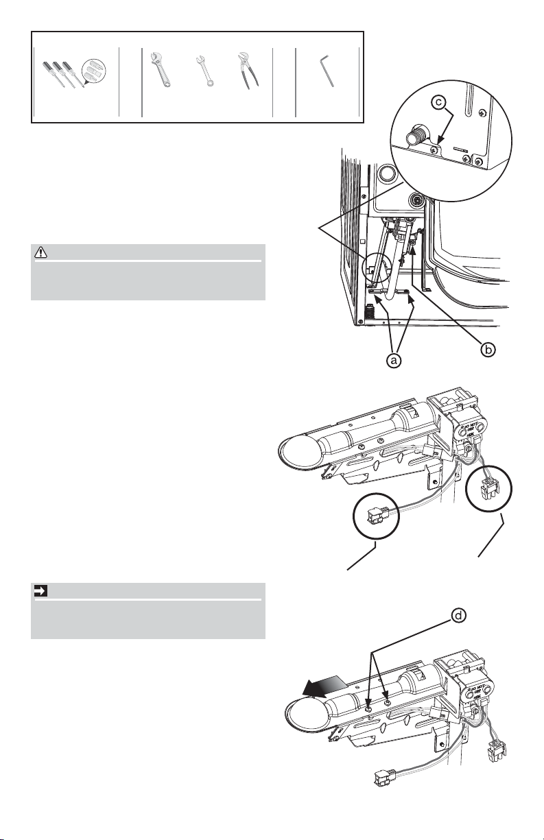
Tools Needed:
Phillips, straight, &
square bit screwdrivers
AND
Adjustable
wrench
OR OR
3/8” or
10 mm
box wrench
PREPARING DRYER FOR
LP CONVERSION
Disconnect electrical power.1.
Shut off gas at the individual shutoff valve.2.
Disconnect fl exible gas supply at back of 3.
dryer.
WARNING
Failure to disconnect electrical and gas supply could result in personal injury or even
death.
Disconnect exhaust venting.4.
Slide dryer away from wall.5.
REMOVING BURNER ASSEMBLY
To gain access to burner assembly, remove 1.
top panel, console, and front panel.
Remove 2 inlet pipe mounting screws (a) 2.
from dryer base.
Remove 1 screw (b) from mounting bracket 3.
to combustion tube.
Remove 1 screw (c) on back of dryer near 4.
threaded gas inlet pipe.
Disconnect long ORANGE and WHITE wire 5.
harness under combustion tube.
Disconnect short ORANGE and YELLOW 6.
wire harness below gas valve.
Carefully remove burner assembly from dryer 7.
cabinet.
IMPORTANT
Take care not to damage the ignitor coils as
you remove the burner assembly. If broken,
the ignitor will not function.
Remove 2 screws (d) from burner tube 8.
mount. Save screws for reassembly. Remove
galvanized burner tube and discard.
Adjustable
pliers
AND
3/16”
allen wrench
ON
BACK
ORANGE/WHITE
ORANGE/YELLOW
2
Page 3
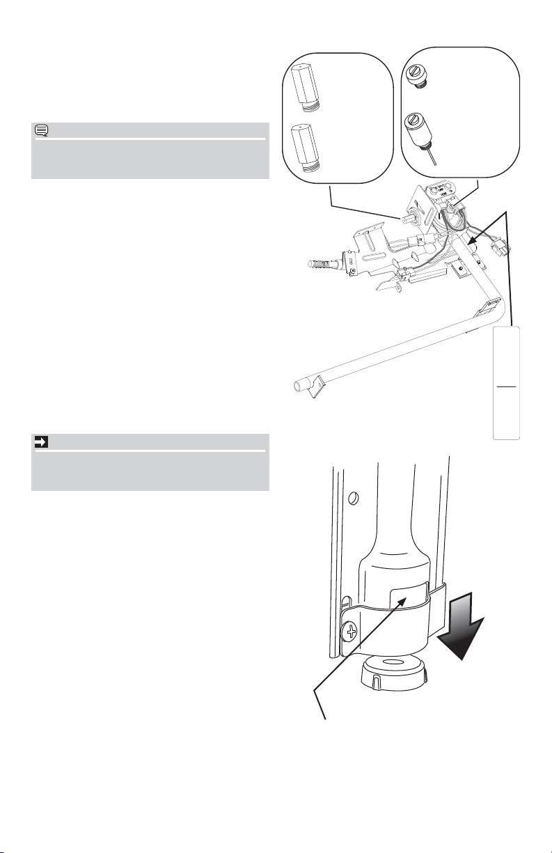
CONVERTING BURNER ASSEMBLY
Remove natural gas orifi ce (stamped “42” or 1.
“44”) and replace with LP orifi ce (stamped
“55”). Tighten securely.
Remove leak limiter from gas valve and re-2.
place with LP blocking pin. Tighten securely.
NOTE
Save natural gas orifi ce (stamped “42” or
“44”) and leak limiter in event dryer might
need to be converted back in the future.
Assemble air shutter to stainless steel burner 3.
tube furnished in installation kit so shutter is
in full open position (see image below). Additional shutter adjustment may be needed
later. Shutter should be assembled so adjusting screw head is accessible from below
after burner assembly is mounted in dryer.
Lay alignment collar on fl at surface and press 4.
stainless steel tube fi rmly onto collar as
shown in image below.
Slide alignment collar around (“55”) LP 5.
orifi ce and mount stainless steel burner tube
to mounting bracket with original screws
removed earlier.
REINSTALLING BURNER ASSEMBLY
Reinstall burner assembly into cabinet by 1.
reversing previous removal instructions.
IMPORTANT
Take care not to damage the ignitor coils as
you install the burner assembly. If broken, the
ignitor will not function.
Apply control conversion label to gas inlet 2.
pipe near control valve to notify future service technicians of conversion.
Apply new rating plate as close to the origi-3.
nal rating plate as possible.
42
42
“42” or “44”
42
42
42
42
orifi ce for
42
42
natural gas
55
55
“55” orifi ce for
55
55
55
55
LP gas
55
55
leak limiter for
natural gas
blocking pin for
LP gas
Cette sécheuse a été
This control has
convertie pour
fonctionner au gaz LP.
been converted for
use with LP gas.
137070500 0807
press tube
onto collar
shutter full open
3
Page 4
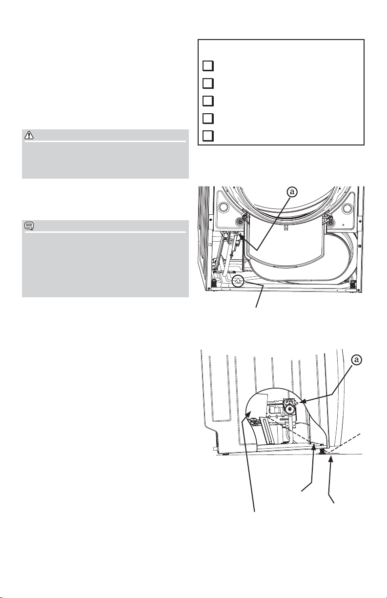
REINSTALLING BURNER ASSEMBLY, con’t
Verify that all kit parts on the list to the right 4.
are installed on the dryer.
DO NOT plug in unit to electricity yet. Apply 5.
approved thread sealer to inlet pipe and
install gas supply. Open gas supply valve to
check for leaks. Spray a soapy water solution on gas supply input on back of dryer
and leak limiter threads on gas burner valve.
Look for bubbles and repair as necessary.
INSTALLED ITEMS
LP orifi ce (stamped “55”)
Blocking pin
Stainless steel burner with
shutter and alignment collar
Control conversion label
adjustable
WARNING
DO NOT TEST WITH AN OPEN FLAME!
Fire, explosion, serious bodily injury and/or
property damage can result from testing a gas
line for leaks with an open fl ame.
ADJUSTING BURNER FLAME
Install front panel, console, and top panel. 1.
Plug in dryer and operate in heat cycle.
NOTE
Before the burner will light, the gas line must
bleed itself of air. If the burner does not light
within 45 seconds of being started, the safety
switch will shut the burner off. If this happens,
press the cancel button and wait 5 minutes
before making another attempt to operate the
dryer.
Place a mirror on the fl oor under the front 2.
panel to observe fl ame through the view port
in the base. You may need to extend the
front legs to view the fl ame in the mirror.
The fl ame should be blue in color. If it is yel-3.
low, repeat the steps to gain access to the
burner, adjust the shutter, reassemble and
observe the fl ame again.
Repeat the above steps until the sputtering 4.
or yellow fl ame disappears.
CHECKING MANIFOLD PRESSURE
Turn off gas supply and follow previous steps 1.
to gain access to the burner assembly.
Remove the pressure tap plug (item “a” in 2.
both images to the right) and install a pressure tap and manometer.
Reassemble dryer and turn on gas supply.3.
Start dryer in heat cycle. Manifold pressure 4.
should be between 7 and 10 inches of water
column when burner is lit.
Turn off gas supply, disassemble dryer, remove 5.
manometer and replace pressure tap plug.
Turn on gas supply and leak check pressure 6.
tap plug with soapy water solution.
Turn off gas supply and reassemble dryer.7.
LP rating plate (English or French)
fl ame view hole in base
view hole
mirror
fl ame in combustion tube
4
Page 5

Instrucciones de instalación
Kit de conversión a gas LP para secadoras a gas natural
ADVERTENCIA
Este kit de conversión debe ser instalado por una agencia de
servicio califi cada, de acuerdo con las instrucciones del fabricante
y con todos los códigos y requisitos aplicables que impongan las
autoridades con jurisdicción. La información contenida en estas
instrucciones debe ser seguida al pie de la letra para minimizar el
riesgo de incendio o explosión o para evitar daños a la propiedad,
lesiones personales o la muerte. La agencia califi cada de servicio
técnico es responsable de la instalación adecuada de este kit.
La instalación no se habrá realizado completa y adecuadamente
hasta que se verifi que el funcionamiento del electrodoméstico
convertido como se especifi ca en las instrucciones del fabricante
provistas con este kit.
ADVERTENCIA
El incumplimiento de las siguientes instrucciones adecuadas y del uso del kit de conversión
correcto puede causar un incendio, una explosión, lesiones personales graves y/o daños a la
propiedad.
llevada a cabo por un TÉCNICO DE SERVICIO CALIFICADO SOLAMENTE. SÓLO USE EL KIT DE
CONVERSIÓN ESPECIFICADO EN EL CATÁLOGO DE PIEZAS PARA EL NÚMERO DE MODELO DE
LA SECADORA QUE SE VA A CONVERTIR.
La conversión se realiza a riesgo y responsabilidad de la persona que la haga y debe ser
IMPORTANTE
Este kit fue diseñado para ser usado con gas embotellado (tanques). La tubería de gas debe •
estar equipada con un regulador de presión de gas que proporcione una presión de gas entre
8" (20 cm) c.d.a. (mínimo) y 11" (28 cm) c.d.a. (máximo) en el punto de conexión a la secadora.
Este kit ha sido aprobado para uso en secadoras fabricadas a partir del 1º de julio de 2008 y •
con quemadores con válvulas de gas que muestren el número de pieza 13118070 o 145493-
000.
Si instala este kit de conversión en la válvula número 13118070, el régimen nominal de entrada •
será de 22.000 BTU/hora. Si instala este kit de conversión en la válvula número 145493-000, el
régimen nominal de entrada será de 20.000 BTU/hora.
El régimen nominal de BTU se refi ere a la cantidad de calor a nivel del mar. Para el uso •
de la secadora en altitudes superiores a los 2.000 pies, el régimen nominal de entrada del
electrodoméstico se deberá reducir en un 4% por cada 1.000 pies de altura por encima del
nivel del mar.
Cumpla con todos los códigos locales y con la Norma Nacional Americana del Código •
Nacional de Gas Combustible ANSI Z 223.1-1988. Si tiene preguntas al respecto y sobre la
instalación, póngase en contacto con el distribuidor de tanques de gas.
LA INSTALACIÓN DEBE SER REALIZADA SEGÚN LOS REQUERIMIENTOS DE •
LAS AUTORIDADES PROVINCIALES CON JURISDICCIÓN Y DE ACUERDO A LOS
REQUERIMIENTOS DEL CÓDIGO DE INSTALACIÓN DE LA NORMA CSA B149.1.
Consulte las instrucciones de instalación del producto para realizar las conexiones de las •
tuberías de suministro de gas a la secadora.
11
137066200 B (0808)
Page 6

n
h
year
with Kit N
Ori
fic
e s
ize
: 5
5
Inp
ing
(Btu/
hr)
:
Piezas del kit:
Tubo de acero inoxidable del quemador1.
Tornillo, #8 (18x0,375)2.
Placa de información de régimen nominal 3.
de conversión (inglés)
Placa de información de régimen nominal
de conversión (francés)
Persiana ajustable4.
Collarín de alineación5.
Pasador de bloqueo6.
Caperuza de gas LP (estampada con el 7.
número “55”)
Etiqueta de control de conversión8.
Herramientas necesarias:
This control has
been converted for
use with LP gas.
55
55
55
55
55
55
55
55
Cette sécheuse a été
convertie pour
fonctionner au gaz LP.
137070500 0807
Cette sécheuse a été convertie le
This dryer was field converted on
was field converted o
année mois jour
day
month
mont
pour fonctionner au gaz LP à l’aide
de la trousse no PCK4100
to LP gas with Kit No.
o.
par
by
(nom et adresse de l’organisme qui
(name and address of organization
a effectué la conversion), qui
making this conversion), who
accepte l’entière resonsabilité de la
accepts the responibility for the
qualité de la conversion.
correctness of this conversion.
Pression à la tubulure
Manifold pressure (”wc):
d’alimentation (”wc):
7” - 10”
7” - 10”
Orifice size: 55
Injecteur numéro: 55
ut rat
Input rating (Btu/hr):
Debit calorifique (Btu/hr):
22,000 (6.45 kWh)
137070401 0807
year
Y
Destornilladores Philips
con punta derecha y
con punta cuadrada
Llave
adjustable
PREPARACIÓN DE LA SECADORA
PARA LA CONVERSIÓN A GAS LP
Desconecte la energía eléctrica.1.
Cierre el suministro de gas en la válvula de 2.
cierre individual.
Desconecte la tubería fl exible de suministro 3.
de gas de la parte trasera de la secadora.
ADVERTENCIA
Si no se desconecta el suministro eléctrico y
de gas antes de realizar cualquier reparación,
podrían ocurrir lesiones personales o incluso
la muerte.
Desconecte el conducto de ventilación de 4.
escape.
Aleje la secadora de la pared.5.
OO
Llave de
3/8” o
10 mm
Pinzas
adjustable
Y
Llave allen
de 3/16”
2
Page 7

DESINSTALACIÓN DEL CONJUNTO
DEL QUEMADOR
Para obtener acceso al conjunto del 1.
quemador, retire el panel superior, la consola
y el panel delantero.
Retire los 2 tornillos de instalación (a) de 2.
la tubería de admisión de la base de la
secadora.
Retire 1 tornillo (b) del soporte de instalación 3.
al tubo de combustión.
Retire 1 tornillo (c) en la parte trasera de 4.
la secadora cerca de la tubería tejida de
admisión de gas.
Desconecte el enchufe preformado largo 5.
ANARANJADO y BLANCO debajo del tubo
de combustión.
Desconecte el enchufe preformado corto 6.
ANARANJADO y AMARILLO debajo de la
válvula de gas.
Retire cuidadosamente el conjunto del 7.
quemador de la secadora.
IMPORTANTE
Tenga cuidado de no dañar las bobinas del
encendedor cuando retire el conjunto del
quemador. Si se dañan, el encendedor no
funcionará.
Retire 2 tornillos (d) del conjunto del tubo 8.
del quemador. Conserve los tornillos para la
reinstalación. Retire el tubo galvanizado del
quemador y deséchelo.
ENCENDIDO
ATRÁS
ANARANJADO/
3
ANARANJADO/
AMARILLO
BLANCO
Page 8

CONVERSIÓN DEL CONJUNTO DEL
QUEMADOR
Retire la caperuza de gas natural (estampada 1.
con el número "42" o "44") y reemplácela con
la caperuza de gas LP (estampada con el
número "55"). Apriétela bien.
Retire el limitador de escapes de la válvula 2.
de gas y reemplácelo con el pasador de
bloqueo de gas LP. Apriétela bien.
NOTA
Conserve la caperuza de gas natural
(estampada con el número "42" o "44") y el
limitador de escapes en caso de que necesite
realizar la conversión inversa en el futuro.
Instale el obturador de aire en el tubo de 3.
acero inoxidable del quemador (incluido
en el kit de instalación) de manera que el
obturador quede completamente abierto
(vea la imagen abajo). Es posible que sea
necesario realizar ajustes adicionales al
obturador más adelante. El obturador debe
ser instalado de manera que la cabeza del
tornillo de ajuste quede accesible desde
abajo después de instalar el conjunto del
quemador en la secadora.
Coloque el collarín de alineación en la 4.
superfi cie plana y presione el tubo de acero
inoxidable fi rmemente sobre el collarín como
se muestra en la imagen abajo.
Deslice el collarín de alineación alrededor 5.
de la caperuza de gas LP ("55") e instale el
tubo de acero inoxidable del quemador en
el soporte de instalación usando los tornillos
originales que se retiraron anteriormente.
REINSTALACIÓN DEL CONJUNTO
DEL QUEMADOR
Reinstale el conjunto del quemador en el 1.
gabinete invirtiendo las instrucciones de
desinstalación.
IMPORTANTE
Tenga cuidado de no dañar las bobinas del
encendedor cuando instale el conjunto del
quemador. Si se dañan, el encendedor no
funcionará.
Coloque la etiqueta de control de conversión 2.
en la tubería de gas cerca de la válvula de
control para notifi car de la conversión a
cualquier técnico de servicio que repare el
electrodoméstico en el futuro.
Coloque la placa de información nueva lo 3.
más cerca posible de la placa original.
Caperuza
42
42
42
“42” o “44”
42
42
42
42
para gas
42
natural
55
55
Caperuza
55
55
55
55
“55” para
55
55
gas LP
obturador
completamente abierto
limitador de
escapes para
gas natural
Pasador de
bloqueo para
gas LP
oprima el
tubo sobre
el collarín
Cette sécheuse a été
This control has
convertie pour
fonctionner au gaz LP.
been converted for
use with LP gas.
137070500 0807
4
Page 9

REINSTALACIÓN DEL CONJUNTO DEL QUEMADOR (cont.)
Verifi que que todas las piezas del kit que 1.
están en la lista a la derecha estén instaladas
en la secadora.
Todavía NO enchufe el electrodoméstico. 2.
Aplique sellante de roscas aprobado a la tubería
de admisión de gas y conecte el suministro de
gas. Abra el suministro de gas y verifi que que
no haya escapes. Rocíe una solución de agua
jabonosa en la conexión de admisión de gas en
la parte trasera de la secadora y en las roscas
del limitador de gas en la válvula. Busque la
presencia de burbujas y, de encontrarlas, haga
las reparaciones necesarias.
PIEZAS INSTALADAS
Caperuza de gas LP (estampada con el
número “55”)
Pasador de bloqueo
Quemador de acero inoxidable con
collarín de alineación y obturador
ajustables
Etiqueta de control de conversión
Placa de información de régimen nominal
de gas LP (inglés o francés)
ADVERTENCIA
¡NO HAGA LA VERIFICACIÓN DE ESCAPES
Si utiliza una llama abierta para verifi car
escapes en la tubería de gas, podría
causar un incendio, una explosión, lesiones
personales graves y/o daños a la propiedad.
CON UNA LLAMA ABIERTA!
AJUSTE DE LA LLAMA DEL QUEMADOR
Instale el panel delantero, la consola y 1.
el panel superior. Enchufe la secadora y
enciéndala en el ciclo de secado con calor.
NOTA
Antes de que se encienda el quemador, la
tubería debe purgar todo el aire que haya en su
interior. Si el quemador no se enciende a los 45
segundos, el interruptor de seguridad apagará
el quemador. Si esto ocurre, presione el botón
“cancel” (anular) y espere 5 minutos antes de
volver a intentar encender la secadora.
Coloque un espejo en el piso debajo del 2.
panel delantero para ver la llama a través
del agujero de observación de la base.
Es posible que deba extender las patas
delanteras para ver la llama en el espejo.
La llama debe ser de color azul. Si la llama 3.
es amarilla, repita los pasos para acceder
al quemador, ajuste el obturador, vuelva
a cerrar el acceso y observe la llama
nuevamente.
Repita los pasos anteriores hasta que 4.
desaparezcan las llamas irregulares o
amarillas.
agujero de observación de
la llama de la base
agujero de
observación
llama en el tubo
de combustión
espejo
5
Page 10

VERIFICACIÓN DE LA PRESIÓN DEL
MÚLTIPLE
Cierre el suministro de gas y siga los pasos 1.
anteriores para obtener acceso al conjunto
del quemador.
Retire el tapón de la válvula de presión (pieza 2.
"a" en las imágenes a la derecha) e instale
una válvula de presión y un manómetro.
Vuelva a armar la secadora y abra el 3.
suministro de gas.
Encienda la secadora en un ciclo con calor. 4.
La presión del múltiple debe estar entre
7 y 10 pulgadas c.d.a. (columna de agua)
cuando el quemador esté encendido.
Cierre el suministro de gas, desinstale la 5.
secadora, retire el manómetro y vuelva a
instalar el tapón de la válvula de presión.
Abra el suministro de gas y verifi que que 6.
no haya escapes en el área del tapón de la
válvula de presión usando una solución de
agua jabonosa.
Cierre el suministro de gas y vuelva a instalar 7.
la secadora.
6
Page 11

Instructions d'installation
Nécessaire de conversion pour sécheuse, du gaz naturel au GPL
AVERTISSEMENT
Ce nécessaire de conversion doit être installé par un technicien
de service après-vente qualifi é conformément aux instructions
du fabricant ainsi qu'à tous les codes et toutes les exigences
des autorités compétentes.
instructions afi n de réduire le risque d'incendie ou d'explosion
ou pour prévenir les dommages matériels, les blessures ou
la mort. Le technicien de service qualifi é est responsable de
l'installation adéquate de ce nécessaire. L'installation n'est pas
correcte ou terminée tant que le fonctionnement de l'appareil
converti n'est pas vérifi é selon les instructions du fabricant
fournies avec le nécessaire.
AVERTISSEMENT
Le non respect des instructions suivantes et l'utilisation d'un nécessaire de conversion incorrect
peuvent causer un incendie, une explosion, des blessures graves et/ou des dommages
matériels. La conversion demeure la responsabilité et se fait au risque de la personne qui
l'effectue et cette personne doit être un TECHNICIEN QUALIFIÉ SEULEMENT. UTILISEZ
SEULEMENT LE NÉCESSAIRE DE CONVERSION SPÉCIFIÉ DANS LE CATALOGUE DE PIÈCES
POUR LE NUMÉRO DE MODÈLE DE LA SÉCHEUSE À CONVERTIR.
Il est nécessaire de suivre ces
IMPORTANT
Ce nécessaire de conversion est conçu pour être utilisé avec du gaz en bouteille (réservoirs). •
La conduite de gaz doit être équipée d'un détendeur de gaz qui fournit une pression de gaz
au raccord de la sécheuse d'un maximum de 203,2 mm (8 po) et d'un minimum de 279,4 mm
(11 po) à la colonne d'eau.
Ce nécessaire est approuvé pour les sécheuses fabriquées après le 30 juin 2008 possédant •
des brûleurs dont la soupape de gaz porte le n° de pièce 13118070 ou 145493-000.
Si ce nécessaire de conversion est utilisé avec la soupape n° 1318070, le débit calorifi que sera •
de 22 000 BTU/h. Si ce nécessaire de conversion est utilisé avec la soupape n° 145493-000, le
débit calorifi que sera de 20 000 BTU/h.
Le débit calorifi que se rapporte à l'entrée de chaleur au niveau de la mer. Pour faire fonctionner •
l'appareil à une altitude supérieure à 609,6 m (2 000 pi), le débit calorifi que de l'appareil doit
être réduit à raison de 4 % pour chaque 304,8 m (1 000 pi) d'altitude au-dessus du niveau de
la mer.
Respectez tous les codes locaux et le code national sur le gaz combustible American National •
Standard ANSI Z 223.1-1988. Pour toute question concernant l'installation, communiquez avec
le détaillant de réservoirs de gaz.
LA CONVERSION SERA EFFECTUÉE CONFORMÉMENT À LA RÉGLEMENTATION DES •
AUTORITÉS PROVINCIALES COMPÉTENTES ET CONFORMÉMENT AUX EXIGENCES DU
CODE D'INSTALLATION CSA B149.1.
Reportez-vous aux instructions d'installation du produit pour connaître les raccordements de •
l'alimentation en gaz de la sécheuse.
1
137066200 B (0808)
Page 12

Composants du nécessaire :
n
h
year
with Kit N
Ori
fic
e s
ize
: 5
5
Inp
ing
(Btu/
hr)
:
Tube de brûleur en acier inoxydable1.
Vis n° 8 (18 x 0,375)2.
Plaque signalétique de conversion - en 3.
anglais
Plaque signalétique de conversion - en
français
Obturateur réglable4.
Bague de réglage5.
Goupille de blocage du détendeur6.
Gicleur GPL (code n° 55)7.
Étiquette de conversion8.
Outils nécessaires :
This control has
been converted for
use with LP gas.
55
55
55
55
55
55
55
55
Cette sécheuse a été
convertie pour
fonctionner au gaz LP.
137070500 0807
Cette sécheuse a été convertie le
This dryer was field converted on
was field converted o
année mois jour
day
month
mont
pour fonctionner au gaz LP à l’aide
de la trousse no PCK4100
to LP gas with Kit No.
o.
par
by
(nom et adresse de l’organisme qui
(name and address of organization
a effectué la conversion), qui
making this conversion), who
accepte l’entière resonsabilité de la
accepts the responibility for the
qualité de la conversion.
correctness of this conversion.
Pression à la tubulure
Manifold pressure (”wc):
d’alimentation (”wc):
7” - 10”
7” - 10”
Orifice size: 55
Injecteur numéro: 55
ut rat
Input rating (Btu/hr):
Debit calorifique (Btu/hr):
22,000 (6.45 kWh)
137070401 0807
year
ET
Tournevis Phillips,
à pointeplate et
à pointe carrée
Clé à
molette
PRÉPARATION DE LA SÉCHEUSE À
LA CONVERSION AU GPL
Coupez l'alimentation électrique.1.
Fermez le gaz au niveau du robinet d'arrêt 2.
manuel individuel.
Débranchez le tuyau fl exible d'alimentation 3.
de gaz à l'arrière de la sécheuse.
AVERTISSEMENT
Le fait de ne pas débrancher l'appareil de
sa source d'alimentation en électricité et
en gaz avant son entretien peut causer des
blessures, voire la mort.
Débranchez la canalisation d'évacuation.4.
Éloignez la sécheuse du mur.5.
OU OU
Clé polygonale
3/8 po ou
de 10 mm
Pince
réglable
ET
Clé hexagonale
de 3/16 po
2
Page 13

RETRAIT DE L'ENSEMBLE DU BRÛLEUR
Pour accéder à l'ensemble du brûleur, 1.
retirez le panneau supérieur, la console et le
panneau avant.
Retirez les deux vis de montage (a) du tuyau 2.
d'entrée de la base de l'appareil.
Retirez une vis (b) du support de montage du 3.
tube de combustion.
Retirez une vis (c) à l'arrière de l'appareil, 4.
près du tuyau d'entrée de gaz fi leté.
Débranchez le long faisceau électrique 5.
ORANGE et BLANC sous le tube de
combustion.
Débranchez le long faisceau électrique 6.
ORANGE et JAUNE sous la soupape de gaz.
Retirez soigneusement l'ensemble du brûleur 7.
de la sécheuse.
L'ARRIÈRE
IMPORTANT
Faites attention de ne pas endommager les
serpentins de l'allumeur lorsque vous retirez
l'ensemble du brûleur. S'ils sont endommagés,
l'allumeur ne fonctionnera plus.
Retirez les deux vis (d) du support de tube de 8.
brûleur. Conservez-les pour le réassemblage.
Retirez et jetez le tube de brûleur galvanisé.
À
ORANGE/BLANC
3
ORANGE/JAUNE
Page 14

CONVERSION DE L'ENSEMBLE DU
BRÛLEUR
Retirez le gicleur de gaz naturel (code n° 42 1.
ou 44) et remplacez-le par un gicleur pour
GPL (code n° 55). Serrez bien.
Retirez le limiteur de gaz de la soupape de 2.
gaz et remplacez-le par une goupille de
blocage pour GPL. Serrez bien.
REMARQUE
Conservez le gicleur de gaz naturel (code n° 42
ou 44) et le limiteur de fuite dans le cas où
l'appareil doit plus tard être converti à nouveau.
Fixez l'obturateur d'air au tube de brûleur en 3.
acier inoxydable fourni avec le nécessaire
d'installation de manière à ce que l'obturateur
soit complètement ouvert (voir l'image
ci-dessous). Un réglage supplémentaire
de l'obturateur sera peut-être nécessaire
ultérieurement. L'obturateur doit être monté
de manière à ce que la tête de la vis de
réglage soit accessible à partir du dessous,
une fois que l'ensemble du brûleur est installé
dans la sécheuse.
Placez la bague de réglage sur une surface 4.
plate et appuyez fermement le tube en acier
inoxydable sur la bague comme il est montré
dans l'image ci-dessous.
Faites glisser la bague de réglage sur le gicleur 5.
GPL (code 55) et fi xez le tube de brûleur en
acier inoxydable au support de montage en
utilisant les vis précédemment retirées.
RÉINSTALLATION DE L'ENSEMBLE
DU BRÛLEUR
Réinstallez l'ensemble du brûleur dans la 1.
sécheuse en suivant les instructions de retrait
en ordre inversé.
IMPORTANT
Faites attention de ne pas endommager les
serpentins de l'allumeur lorsque vous installez
l'ensemble du brûleur. S'ils sont endommagés,
l'allumeur ne fonctionnera plus.
Posez l'étiquette de conversion au tuyau 2.
d'entrée de gaz, près du robinet de réglage
pour aviser tout éventuel technicien de la
conversion.
Installez la nouvelle plaque signalétique aussi 3.
près que possible de la plaque signalétique
actuelle.
42
42
Gicleur n° 42
42
42
42
42
ou 44 pour
42
42
gaz naturel
55
55
Gicleur n° 55
55
55
55
55
pour GPL
55
55
Obturateur
complètement ouvert
Limiteur de
fuite pour gaz
naturel
Goupille de
blocage pour
GPL
Insérez le
tube dans
la bague
Cette sécheuse a été
This control has
convertie pour
fonctionner au gaz LP.
been converted for
use with LP gas.
137070500 0807
4
Page 15

RÉINSTALLATION DE L'ENSEMBLE
DU BRÛLEUR, suite
Assurez-vous que toutes les pièces du 1.
nécessaire inscrites dans la liste de droite
sont installées sur la sécheuse.
NE BRANCHEZ PAS l'alimentation électrique 2.
à ce moment. Enduisez le tuyau d'entrée
d'un scellant à fi lets approuvé et raccordez
l'alimentation en gaz. Ouvrez le robinet
d'alimentation de gaz pour détecter les fuites.
Vaporisez une solution d'eau savonneuse
sur l'alimentation en gaz à l'arrière de la
sécheuse et sur les fi lets du limiteur de fuite
de la soupape du brûleur. Décelez toute bulle;
réparez au besoin.
AVERTISSEMENT
N'EFFECTUEZ PAS LA VÉRIFICATION À
L'AIDE D'UNE FLAMME NUE!
La détection des fuites à l'aide d'une fl amme
nue pourrait provoquer un incendie, une
explosion, des blessures graves et/ou des
dommages matériels.
RÉGLAGE DE LA FLAMME DU
BRÛLEUR
Installez le panneau avant, la console, et le 1.
panneau supérieur. Branchez la sécheuse et
démarrez un cycle de chaleur.
REMARQUE
Avant que le brûleur ne s'allume, l'air présent
dans la conduite de gaz doit être évacué. Si le
brûleur ne s'allume pas dans les 45 secondes
suivant la mise en marche de la sécheuse,
l'interrupteur de sécurité éteindra le brûleur.
Si cela se produit, appuyez sur la touche
Annuler (Cancel) et attendez 5 minutes avant
d'essayer à nouveau.
Placez un miroir sur le plancher, sous le 2.
panneau avant, pour observer la fl amme par
l'orifi ce d'inspection situé dans la base. Vous
devrez
peut-être allonger les pieds avant pour être
en mesure de voir la fl amme dans le miroir.
La fl amme doit être bleue. Si elle est jaune, 3.
répétez les étapes qui vous donnent accès
au brûleur, réglez l'obturateur, remontez le
tout et observez à nouveau la fl amme.
Répétez les étapes ci-dessus jusqu'à ce que 4.
la fl amme jaune disparaisse et que la fl amme
soit uniforme.
ÉLÉMENTS INSTALLÉS
Gicleur GPL (code n° 55)
Goupille de blocage du détendeur
Brûleur en acier inoxydable avec
teur réglable
Étiquette de conversion
Plaque signalétique de GPL - en français
ou en anglais
et bague de réglage
Orifi ce d'inspection de la
fl amme dans la base
Orifi ce
d'inspection
Flamme dans le tube
de combustion
obtura-
Miroir
5
Page 16

VÉRIFICATION DE LA PRESSION DU
COLLECTEUR
Fermez l'alimentation en gaz et suivez 1.
les étapes précédentes pour accéder à
l'ensemble du brûleur.
Retirez le bouchon de tubulure de prise 2.
de pression (élément « a » dans les deux
images de droite) et installez un robinet
manométrique.
Remontez la sécheuse et ouvrez 3.
l'alimentation en gaz.
Démarrez un cycle de chaleur. La pression 4.
du collecteur devrait se situer entre 177,8
et 254 mm (7 et 10 po) de colonne d'eau
lorsque le brûleur est allumé.
Fermez l'alimentation en gaz, démontez la 5.
sécheuse, retirez le manomètre et replacez le
bouchon de tubulure de prise de pression.
Ouvrez l'alimentation en gaz et vérifi ez le 6.
bouchon de tubulure de prise de pression
avec une solution d'eau savonneuse pour
détecter tout signe de fuite.
Fermez l'alimentation en gaz et remontez la 7.
sécheuse.
6
 Loading...