

Page 1
R
BOTTOM FREEZER REFRIGERATOR
REFRIGERATOR
SERVICE MANUAL
CAUTION
BEFORE SERVICING THE PRODUCT
READ THE SAFETY PRECAUTIONS IN THIS MANUAL
795.78342.800
ENGLISH
795.78343.800
795.78344.800
795.78346.800
795.78349.800
795.78352.800
795.78353.800
795.78354.800
795.78356.800
795.78359.800
Sears, Roebuck and Co., Hoffman Estates, IL60179 U.S.A.
www.sears.com
Page 2

CONTENTS
SAFETY PRECAUTIONS ..........................................................................................................
1. SPECIFICATIONS ..................................................................................................................
2. PARTS IDENTIFICATION .......................................................................................................
3. DISASSEMBLY ......................................................................................................................
3.1 Door ..................................................................................................................................
3.2 To remove the dispenser ....................................................................................................
3.3 Fan and fan motor ..............................................................................................................
3.4 Defrost control assembly ...................................................................................................
3.5 Lamp .................................................................................................................................
3.6 Refrigerator control box .....................................................................................................
3.7 Multi duct ...........................................................................................................................
3.8 How to remove and reinstall the pullout drawer ...................................................................
3.9 Cover Valve .......................................................................................................................
4. COMPRESSOR ELECTRICAL .............................................................................................
4.1 Compressor ......................................................................................................................
4.2 PTC-Starter .......................................................................................................................
4.3 OLP (overload protector) ...................................................................................................
4.4 To remove the cover PTC (only if applies) ...........................................................................
4.5 To remove the COMBO (only if applies) ..............................................................................
5. CIRCUIT DIAGRAM ...............................................................................................................
6. TROUBLESHOOTING ...........................................................................................................
6.1 Compressor and electrical components .............................................................................
6.2 PTC/ COMBO and OLP .....................................................................................................
.
6.3 Other electrical components ..............................................................................................
6.4 Service diagnosis chart ......................................................................................................
6.5 Refrigeration cycle .............................................................................................................
6.6 Troubleshooting with error .................................................................................................
7. ICEMAKER OPERATING PRINCIPLES AND REPAIR ..........................................................
7.1 Operation Principle ............................................................................................................
.
7.2 Ice maker functions ............................................................................................................
7.3 Defect diagnosis function ...................................................................................................
8. WATER FILTER ......................................................................................................................
8.1 Water filter cartridge replacement ......................................................................................
8.2 Water dispenser (on some models) ....................................................................................
9. DESCRIPTION OF FUNCTION & CIRCUIT OF MICOM .........................................................
9.1 Function ............................................................................................................................
9.2 PCB function .....................................................................................................................
9.3 Resistance specification of sensor .....................................................................................
9.4 Troubleshooting ................................................................................................................
9.5 Main PWB assembly and parts list .....................................................................................
9.6 PWB diagram ....................................................................................................................
10. EXPLODED VIEW AND REPLACEMENT PART LIST .........................................................
795.783**.800 .......................................................................................................................
2
3
5
6
6
7
8
8
8
9
9
9
12
13
13
13
14
14
14
15
16
16
17
18
19
20
22
30
30
31
32
33
33
34
35
35
40
48
49
51
53
54
60
SAFETY PRECAUTIONS
Please read the following instructions before servicing your
refrigerator.
1. Check the refrigerator for current leakage.
2. To prevent electric shock, unplug before servicing.
3. Always check line voltage and amperage.
4. Use standard electrical components.
5. Don´t touch metal products in the greezer with wer hands.
This may cause frost bite.
6. Prevent water from spiling on to electrical elements or the
machine parts.
- 2 -
7. Before tilting the refrigerator, remove all materials from on
or in the refrigerator.
8. When servicing the evaporator, wear gloves to prevent
injuries from the sharp evaporator fins.
9. Service on the refrigerator should be performed by a
qualified technician. Sealed system repair must be
performed by a CFC certified technician.
Page 3

1. SPECIFICATIONS
1-1 DISCONNECT POWER CORD BEFORE SERVICING IMPORTANT RECONNECT ALL GROUNDING
DEVICES.
All parts of this appliance capable of conducting electrical current are grounded. If grounding wires, screws, straps, clips, nuts or
washers used to complete a p ath to ground are removed for service, they must be returned to their original position and properly
fastened.
1-2 IMPORTANT NOTICE
This information is intended for use by individuals possessing adequate backgrounds of electrical, electronic and mechanical
experience. Any attempt to repair a major applaince may result in personal injury and property damage. The manufacturer or
seller cannot be responsible for the interpretation of this information, nor can it assume any liability in connection with its use.
1-3 ELECTRICAL SPECIFICATIONS
Temperature Control (Position: MID) ......................................................................................................................-6°F to +8°F
Defrost Control .........................................................................................................................................................Automatic
Defrost Thermostat ...........................................................................................................................................................50°F
Electrical Rating : 115VAC, 60Hz .....................................................................................................................................1 - 5 A
Maximum Current Leakage ............................................................................................................................................0.5mA
Maximum Ground Path Resistance ..........................................................................................................................0.14Ohms
Energy Consumption ...............................................................................................................23cuft 466kWh/yr (Energy star)
1-4 NO LOAD PERFORMANCE
Control Position : MID/MID
And ambient of: 70°F 90°F
Fresh Food, °F ......................................................33°F to 41°F ..........................................................................33°F to 41°F
Frozen Food, °F .....................................................-4°F to +4°F ...........................................................................-4°F to +4°F
Percent Running Time ..............................................25% - 35% .............................................................................45% - 60%
1-5 REFRIGERATION SYSTEM 1-6 INSTALLATION
Minimum Compressor Capacity Vacuum ..........................21 in Clearance must be provided at top, sides and rear of the
Minimum Equalized Pressure refrigerator for air circulation.
at 70°F ..............................................................49PSIG AT TOP ...........................................................................1in
at 90°F ..............................................................56PSIG AT SIDES ..................................................................1/18 in
Refrigerant R134a ..........................................................4.2oz AT REAR .........................................................................1in
Compressor ..........................................................-700 BTU/hr
- 3 -
Page 4
PERFORMANCE DATA
(NORMAL OPERATING CONDITIONS)
AMB WATTS
70°F
90°F
110°F
98 (+10 / -10)
98 (+10 / -10)
103 (+5 / -5)
1-8 AIR FLOW
SYSTEM PRESSURE (PSIG)
HIGH SIDE LOW SIDE
98 (+5 / -3)
132 (+3 / -3)
180 (+5 / -5)
(-5) to (-2)
(-4) to 1
(-2) to 3
1-7 REPLACEMENT PARTS
Thermistor assembly (COMBO)...........
Defrost Thermostat ..............................
Defrost Heater .....................................
Evaporator fan motor ..........................
Capacitor .............................................
Compressor (Hi-Side) ..........................
Compressor (Lo-Side) .........................
Condenser ...........................................
Dryer ...................................................
Condenser fan motor ...........................
Temperature Control ............................
Main Control ........................................
Harness assembly.................................
EBG43493101
6615JB2005C
5300JB1100J
4681JK1004A
0CZZJB2012J
TCA32125901
5421JJ1001B
5403JJ1007A
5851JJ2002B
4681JB1029J
6871JB1439C
6871JK1011G
6877JK2017C
EVAPORATOR FAN
DRYER
COMPRESSOR
EVAPORATOR
HOT LOOP
CONDENSER
COLD AIR
MIXED AIR
AIR RETURN TO
EVAPORATOR
CONDENSER FAN
FRESH FOOD
Vegetable box
FREEZER
M
A
- 4 -
Page 5
2. PARTS IDENTIFICATION
O
A
B
C
D
E
F
G
H
N
M
L
K
J
I
Use this section to become more familiar with the parts and features.
NOTE:This guide covers several different models.The refrigerator you have purchased may have some
or all of the items listed below.The locations of the features shown below may not match your model.
A
Refrigerator Light
Refrigerator Shelves
B
Snack Pan
C
Crisper
D
Adjusta Cube Ice Maker
E
Ice Bin
F
Durabase
G
Divider
H
I
Glide-Out Drawer Basket
Freezer Light
J
K
Egg Box
Modular Door Bins
L
Can Rack*
M
Dairy Corner
N
Filter
O
*On some models
- 5 -
Page 6
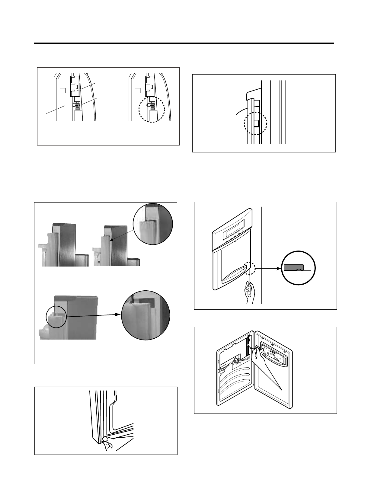
3. DISASSEMBLY
3-1 DOOR
Left Door
• Loosen the screws and remove the cover on back side (see
figure A).
• Disconnect water supply tube by pusshing back on the
disconnect ring (3).
• Loosen the cover screws (1).
• Disconnect door switch wire (2).
• Disconnect wire harness (4).
• Pull out the tube (5).
• Loosen hinge bolts (6).
• Lift off the top hinge (7).
• Place the door on a non-scratching surface with the inside up.
Right Door
Loosen the cover screws (1).
Disconnect door switch wire (2).
Disconnect wire harness (3).
Loosen ground screw (4).
Loosen hinge bolts (5).
Lift off the top hinge (6).
Place the door on a non-scratching surface with
the inside up.
(1)
(1)
Door Gasket Removal
1. Remove door frame cover
Starting at top of cover and working down, snap cover
out and away from door.
Frame Cover
Handle
Figure 2
2. Remove gasket bracket clips
There are two clips on each door. Start bracket removal
near one of the middle clips.
1) Pull gasket back to expose gasket bracket clip and
door frame.
2) Insert a flat tip screwdriver into seam between gasket
bracket and door frame and pry back until clips snap
out.
3) Continue prying back along seam until all clips snap
out.
(2)
(4)
(6)
(7)
(5)
(2)
(3)
LEFT RIGHT
A
Figure A
Figure 1
(5)
(4)
(6)
Door
Frame
Gasket
Bracket Clip
Figure 3
Flat Tip
Screwdriver
Gasket
Bracket
3. Remove gasket
Pull gasket free from gasket channel on the three
remaining sides of door.
3333
Figure 4
Door Gasket Replacement
1. Insert gasket bracket clips
1) Insert gasket bracket edge beneath door frame edge.
2) Turn upper gasket bracket spring so that both spring
ends are in the door channel.
- 6 -
Page 7
3) Push in clip until you hear it snap securely into place.
Gasket
Bracket Clip
Spring
Door
Frame
Correct Incorrect
Figure 5
4) Push in remaining two clips until you hear each snap
securely into place.
Note: Make sure that no part of gasket bracket edge
protrudes from beneath door frame edge.
2. Insert gasket into channel
1) Snap gasket assembly into the door bracket.
Inserting the Gasket Assembly into the Bracket Door.
3. Replace door frame cover
Starting at top of cover and working down, snap the cover
back into door.
Figure 8
3-2 TO REMOVE THE DISPENSER
1. Use flat tip screwdriver to pry back hooks on botton
underside of cover dispenser.
Correct
Incorrect
Figure 6
2) Press gasket into channel on the three remaining
sides of door.
Figure 7
Figure 9
2. Pry off cover dispenser.
Figure 10
Disconnect wire harness.
3. Replace cover dispenser in opposite manner and order
of removal.
- 7 -
Page 8
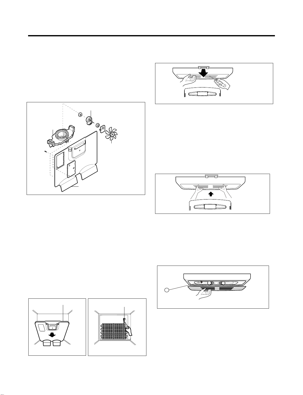
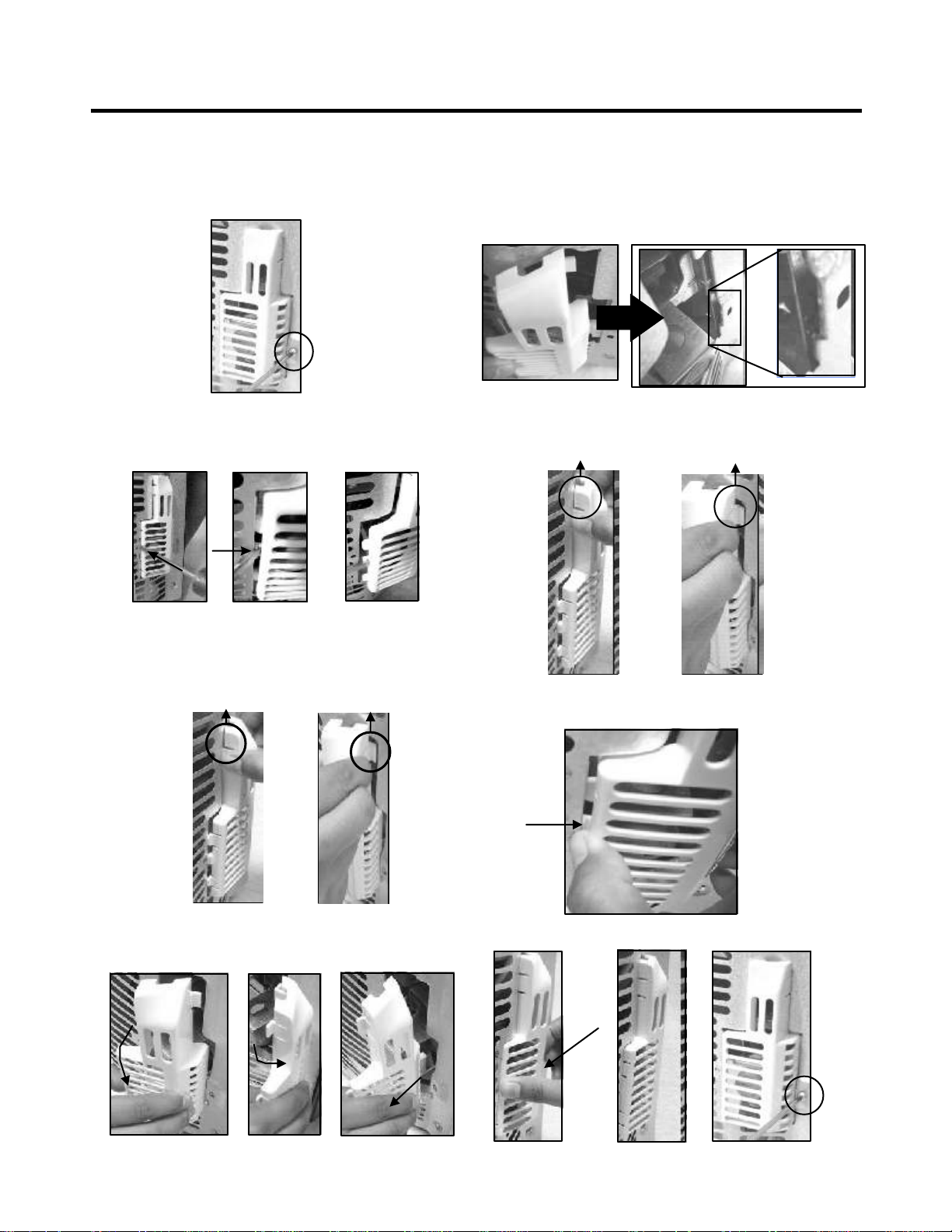
3-3 FAN AND FAN MOTOR
1. Remove the freezer shelf. (If your refrigerator has an
icemaker, remove the icemaker first).
2. Remove the plastic guide for slides on left side by
unscrewing phillips head screws.
3. Remove the grille by removing one screw and pulling the
grille forward.
4. Remove the Fan Motor assembly by loosening 2 screws.
5. Pull out the fan and separate the Fan Motor and Bracket.
FAN MOTOR
3-5 LAMP
Figure 14
BRACKET
MOTOR
FAN
GRILLE
Figure 11
3-4 DEFROST CONTROL ASSEMBLY
Defrost Control assembly consist pf Defrost Sensor and
FUSE-M.
The defrost Sensor wotks to defrost automatically. It is
attached to the metal side of the Evaporator and senses its
Temperature.
Fuse-M is a safety device for preventing over-heating of the
evaporator area when defrosting.
At 72°C, it turns the Defrost Heater off.
1. Pull out the grille assembly. (Figure 12).
2. Separate the connector with the Defrost Control assembly
and replace the Defrost Control assembly after cutting the tie
wrap. (Figure 13).
3. Be sure to retire the wires when reassembling after
service.
3-5-1 To change the refrigerator light
1. Unplug the power cord from the outlet.
2. Remove refrigerator shelves.
3. Release the hooks on the front of the light shield with the help
of a flat screwdriver and pull the shield down to remove it.
4. Turn the bulb counterclockwise.
5. To assemble, first insert the hooks at the back and then push
up the light shield.
Figure 15
3-5-2 To change the freezer light
1. Unplug refrigerator or disconnect power.
2. Reach behind light shield to remove bulb.
3. Replace bulb with a wattage indicated in the refrigerator
section, as shown in picture 1.
4. Plug in refrigerator or reconnect power.
1111
GRILLE ASSEMBLY
Figure 12
DEFROST-CONTROL
ASSEMBLY
Figure 13
Figure 16
- 8 -
Page 9
3-6 REFRIGERATOR CONTROL BOX
1. First, remove all shelves in the refrigerator, then nremove the
refrigerator controll box by loosening 2 screws.
CONTROL BOX
2) Remove the lower drawer.
COVER LAMP
Figure 17
2. Remove the Refrigerator Control Box by pulling it downward.
3. Disconnect the lead wire on the right position and separate
the lamp sockets.
3-7 MULTI DUCT
1. Remove the upper cap by
using a flat screwdriver,
and remove 2 screws.
(Figure 18)
2. Disconnect the lead wire
On the bottom position.
Figure 18
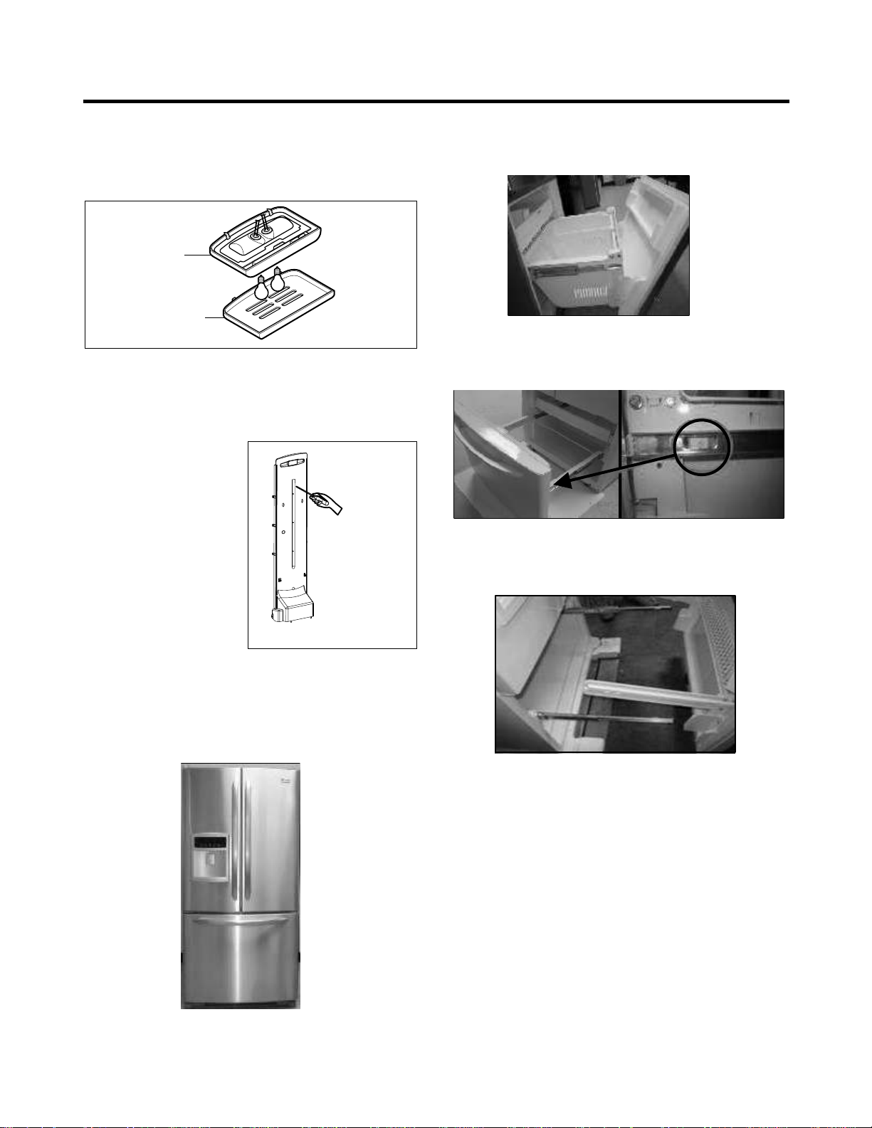
3-8 HOW TO REMOVE AND REINSTALL THE PULL OUT
DRAWER
3-8-1 Follow steps to remove
1) Open the freezer door.
3) Remove the two screws from the guide rails (one from each
side).
4) Lift the freezer door up to unhook it from the rail support and
remove. Pull both rails to full extension.
- 9 -
Page 10
5) First: Remove the gear from the left side first by releasing
the tab behind the gear, place a screwdriver between the
gear and the tab and pull up on the gear.
Second: Remove the center rail.
Third: Remove the gear from the right side by following the
same steps for the left side.
NOTE: This tab must
be pushed in
to release the gear.
2) Insert the rail into the right side gear. Gears do not need to
be perpendicular to each other.
3-8-2 Follow steps to reinstall
1) Reinstall the right side gear into the clip.
3) Insert the rail into the left side gear, and insert the gear into
the clip.
4) The rail system will align itself by pushing the rails all the
way into the freezer section.
Pull the rails back out to full extension.
- 10 -
Page 11
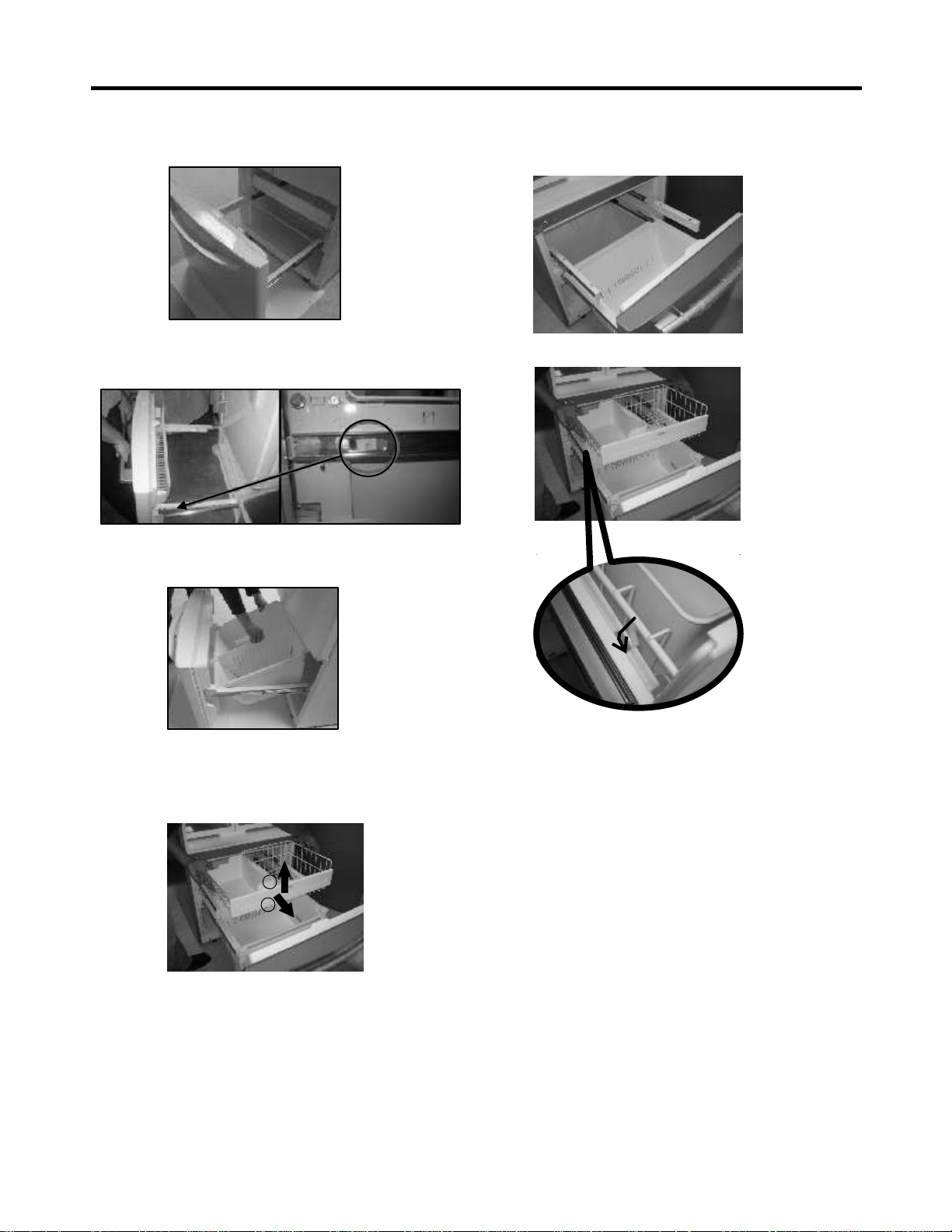
5) Reinstall the freezer door by inserting the rail tabs into
the guide rail.
6) Reinstall the two screws into the guide rails (one from
each side).
7) Reinstall the lower drawer, and close the freezer door.
2. To install, pull both rails out to full extension. Hook the
basket supports into the rail tabs and push to the back of
compartment.
3-8-3 GLIDE OUT DRAWER BASKET
1. To remove, lift basket up and pull out straight out.
1
2
- 11 -
Page 12
3-9 COVER VALVE
-Disasssembly
1. Remove the screw.
2. Push and then push to the right and release
- Assembly
1. Insert the cover valve as shown n the picture, push to
insert (may need force).
2. Insert hook a & b.
a
b
3. Release hooks a & b.
a
b
4. Turn the cover valve 120° as shown in the picture, then
release it.
3. Push to the right to insert the cover valve.
4. Then push and release. Install the screw.
- 12 -
Page 13
4. COMPRESSOR ELECTRICAL
4-1 COMPRESSOR
4-1-1 Role
The compressor intakes low temperature and low pressure
gas from the evaporator of the refrigerator and compresses
this gas to high temperature and high pressure gas. It then
delivers the gas to the condenser.
4-1-2 Composition
The compressor includes overload protection. The PTC
starter and OLP (overload protector) are attached to the
outside of the compressor. Since the compressor is
manufactured to tolerances of 1 micron and is hermetically
sealed in a dust and moisture-free environment, use extreme
caution when repairing it.
4-1-3 Note for Usage
(1) Be careful not to allow over-current.
(2) If compressor is dropped or handled carelessly, poor
operation and noise may result.
(3) Use proper electric components appropriate to the
particular compressor in your product.
(4) Keep compressor dry.
If the compressor gets wet (in the rain or a damp
environment) and rust forms in the pin of the Hermetic
Terminal, poor operation and contact may result. If the
hermetic connector rusts out or fails, refrigerant and oil will be
expelled into the contact area, probably resulting in smoke
and fire.
(5) When replacing the compressor, be careful that dust,
humidity, and soldering flux don´t contaminate the inside of
the compressor. Contamination in the cylinder may cause
noise, improper operation or even cause it to lock up.
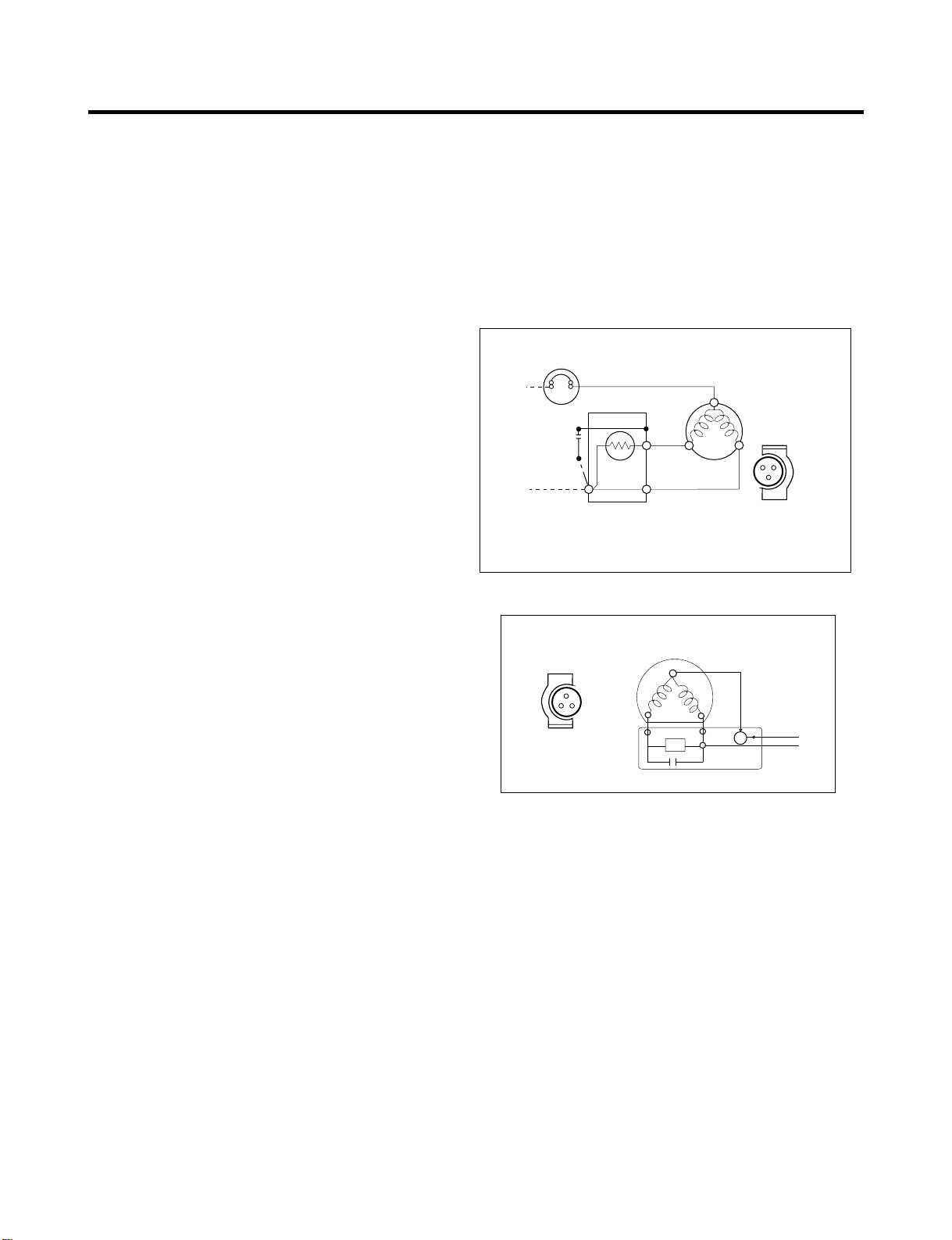
4-2 PTC-STARTER/ COMBO
4-2-1 Composition of PTC- Starter
4-2-4 Role of Combo TSD
(1) The combo is attached to the sealed compressor and is
used for the operation and protect the motor.
(2) The compressor is a single phase induction motor. During
the starting and operation, the combo allows current flow to
both the start and main winding.
4-2-5 PTC/Combo - Applied Circuit Diagram
Starting Method for the Motor
PTC DIAGRAM
OVERLOAD PROTECTOR
N
PTC
2
L1
Resistance Starter Capacitor Running
3
PTC STARTER
5
6
C
COMPRESSOR
MOTOR
S
M
S
SEALED
TERMINAL
M
Figure 17
COMBO DIAGRAM
COMPRESSOR
MOTOR
T
MA
AS
IN
M
SEALED
TERMINAL
S
T R
S
PTC
C
M
N
OLP
L
LINE
(1) PTC (Positive Temperature Coefficient) is a no-contact
semiconductor starting device which uses ceramic material
consisting of BaTiO3.
(2) The higher the temperature is, the higher the resistance
value. These features are used as a starting device for the
motor.
4-2-2 Role of PTC-Starter
(1) The PTC is attached to the Sealed Compressor and is
used for starting the motor.
(2) The compressor is a single-phase induction motor. During
the starting operation, the PTC allows current flow to both the
start winding and main winding.
4-2-3 Combo TSD
TSD (Time Starting Device) is a new electronic starting
system for high efficiency compressors due to the following
characteristics:
(1) Combo concept-overload protector, electronic board and
cover in a single casing.
(2) Fully electronic concept.
(3) Full integration of starting and protection devices.
(4) Free from mechanical and electromagnetic noises.
- 13 -
4-2-6 Motor Resarting and PTC/ Combo Cooling
(1) It requires approximately 5 minutes for the pressure to
equalize before the compressor can restart.
(2) The PTC/Combo device generates hea during operation.
Therefore, it must be allowed to cool before the compressor
can restart.
4-2-7 Relation of PTC-Starter / Combo and OLP
(1) If the compressor attempts to restart before the
PTC/Combo device is cooled, the PTC/Combo device will
allow current to flow only to the main winding.
(2) The OLP will open because of the over current condition.
Thissame process will continue (3 to 5 times) when the
compressor attempts to restart until the PTC/Combo device
has cooled. The corret OLP must be properly attached to
prevent damage to the compressor.
Parts may appear physically identical but could have different
electrical ratings. Replace parts by part number and model
number. Using an incorrect part could result in damage to the
product, fire, injury, or possibly death.
Page 14
4-2-8 Note for using the PTC-Starter / Combo
(1) Be careful not to allow over-voltage and over-current
(2) Do not drop or handle carelessly.
(3) Keep away from any liquid.
If liquid such as oil or water enters the PTC/Combo,
PTC/Combo materials may fail due to breakdown of their
insulating capabilities.
(4) If the exterior of the PTC/Combo is damaged, the
resistance value may be altered. This can cause damage to
the compressor and result in a no-start or hard-to-start
condition.
(5) Always use the PTC/Combo designed for the compressor
and make sure it is properly attached to the compressor.
Parts may appear physically identical but could have different
electrical ratings. Replace parts by part number and model
number. Using an incorrect part could result in damage to the
product, fire, injury, or possibly death.
4-3 OLP (OVERLOAD PROTECTOR)
4-3-1 Definition of OLP
(1) OLP (OVERLOAD PROTECTOR) is attached to the
compressor and protects the motor by opening the circuit to
the motor if the temperature rises activating the bimetal
spring in the OLP.
(2) When high current flows to the compressor motor, the
bimetal wors by heating the heater inside the OLP, and the
OLP protects the motor by cutting off the current flowing to
the compressor motor.
4-3-2 Role of the OLP
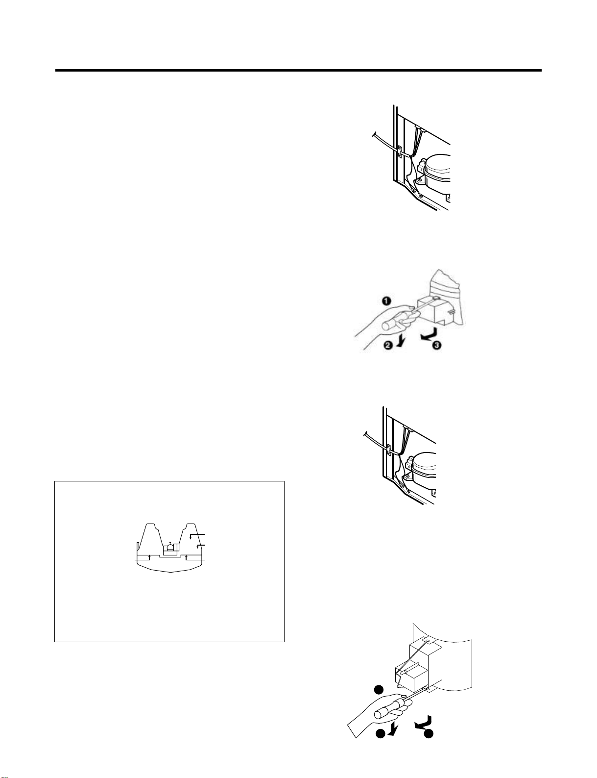
4-4 TO REMOVE THE COVER PTC (only if applies)
(1) Remove the cover Back M/C.
(2) Disconnect two housing upper side of comp connected in.
(3) Loosen two screws on comp base.
(4) Use a L-shaped flap tool to pry off the cover.
(5) Assembly in reverse order of disassembly.
4-5 TO REMOVE THE COMBO (only if applies)
(1) The OLP is attached to the sealed compressor used for
the refrigerator. It prevents the motor coil from being started
in the compressor.}
(2) For normal operation of the OLP, do not turn the adjust
screw of the OLP in anyway.
(OVERLOAD PROTECTOR cross section)
Customer part
number
12345678
Lot code/
date code
Physical
termination
part number
Electrical
characteristics
part number
330 FBYY -S1 BOX98
Figure 18
(1) Remove the cover Back M/C.
(2) Disconnect two housing upper side of comp connected in.
(3) Loosen two screws on comp base.
(4) Use a flat screwdriver to take off the clip from the lower
side.
(5) Take the combo off.
(6) To assembly the side with the “U” form is hooked in the
central part of the compressor base.
(7) Press the “A” point and lift the “B” point to hook to
compressor.
B
A
(5) (5) (5)
111
- 14 -
222
333
Page 15
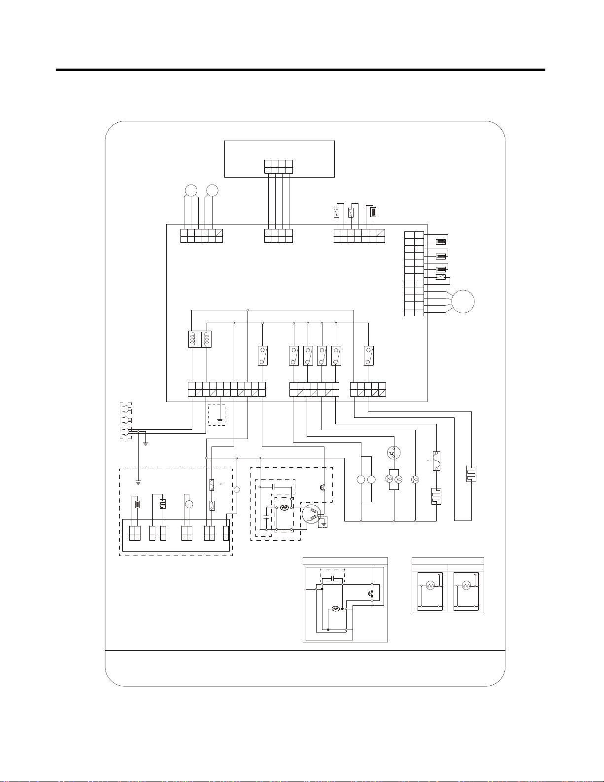
5. CIRCUIT DIAGRAM
PWB(PCB) ASSEMBLY,DISPLAY
BK
4
C-FAN
F-FAN
SB
BL
BO
2RD3
1
RT-SENSOR
PUMP S/W
R-DOOR S/W
WH
1
CON4
BL
BK
GY
PR
3
2
5
4
6
BK
CON6
PWB(PCB) ASSEMBLY, MAIN
L1
3
4
5
6
8
10 7
9
POWER
SUPPLY
CORD
N
L
GN/YL
(GN)
CON1
11
GN
YL
BN
BL
/YL
BL
BN
GN/
YL
PCB EARTH
YL
ICE MAKER PART
GN/YL
(GN)
(98 C)
FUSE-M
BK
M
MOTOR
SHEATH
HEATER,
ICE SENSOR
WH
WH
WH
1
2
1
CON5
CON4
BK
WH
WH
1
2
1
CON2
CON3
S/W
POWER
ICE MAKER
BK
BL
RD
2
1
1
CON1
CON6
PWB (PCB) ASSEMBLY, ICE MAKER
*PLUG TYPE, ICE MAKER PART, CAPACITOR PART, PCB EARTH,
P.T.C START OPTION, COMP' EARTH PART AND COMP'
ACCESSORIES ON CIRCUIT DIAGRAM ARE SUBJECT TO
CHANGE IN DIFFERENT LOCALITIES AND MODEL TYPE.
2
BL
WH
BL
WH
V
I/MAKER W/VALVE
BL
COMP' ACCESSORIES
1
CAPACITOR PARTCAPACITOR PART
Cr
RD
Cs
BO
1
2
PTC STARTER
SB
BL
3
4
5
7
6
PK
PR
CON2
PK
PR
PK
22
SMS
44 55
M
33 66
* ALTERNATIVE COMP' ACCESSORIES
BL
3
4
2
RD
BN
RD
BK
OLPOLP
GNGN
/YL/YL
(GN)(GN)
COMP' EARTHCOMP' EARTH
PARTPART
Cr
N
BN
PTC
GY
1
CON7
1
GY
2
CON3
RD
BN
YL
BN
7
6
5
4
3
2
1
5BK4
3
BN
BL
BL
BN
THERMOSTAT
V V
R-LAMPS
CON5
BL
12
BL
11
10
WH
9
WH
BO
8
BO
7
6
PK
5
PK
4
YL
3
2
BL
1
F-SENSOR
R-SENSOR
DEF-SENSOR
F-DOOR S/W
STEPPING
MOTOR
(72 C)
FUSE-M
RD
F-LAMP
FRENCH DOOR HEATER
DISPENSER W/VALVE PART
BL
BL
BK
L
OLP
BL
* P.T.C START OPTION
MC,MQ COMP'
4
3 2
HEATER,SHEATH
BL
2
BL
EG COMP'
3
5
6
4
56
BK:BLACK
COMBO KIT(PTC+OLP)
BN:BROWNWH:WHITE
PK:PINKYL:YELLOW
GN:GREEN
BO:BRIGHT ORANGE
GY:GREYPR:PURPLE
MEZ48108404
RD:REDSB:SKY BLUE
BL:BLUE
- 15 -
Page 16
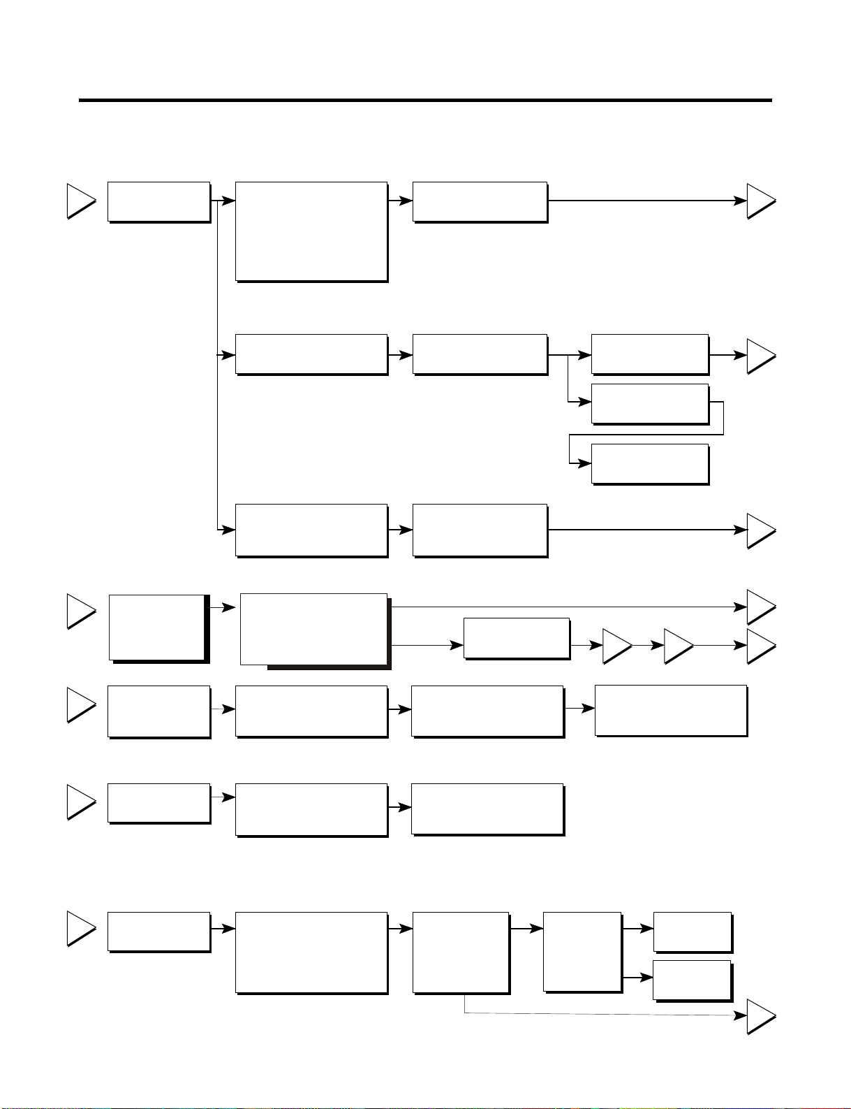
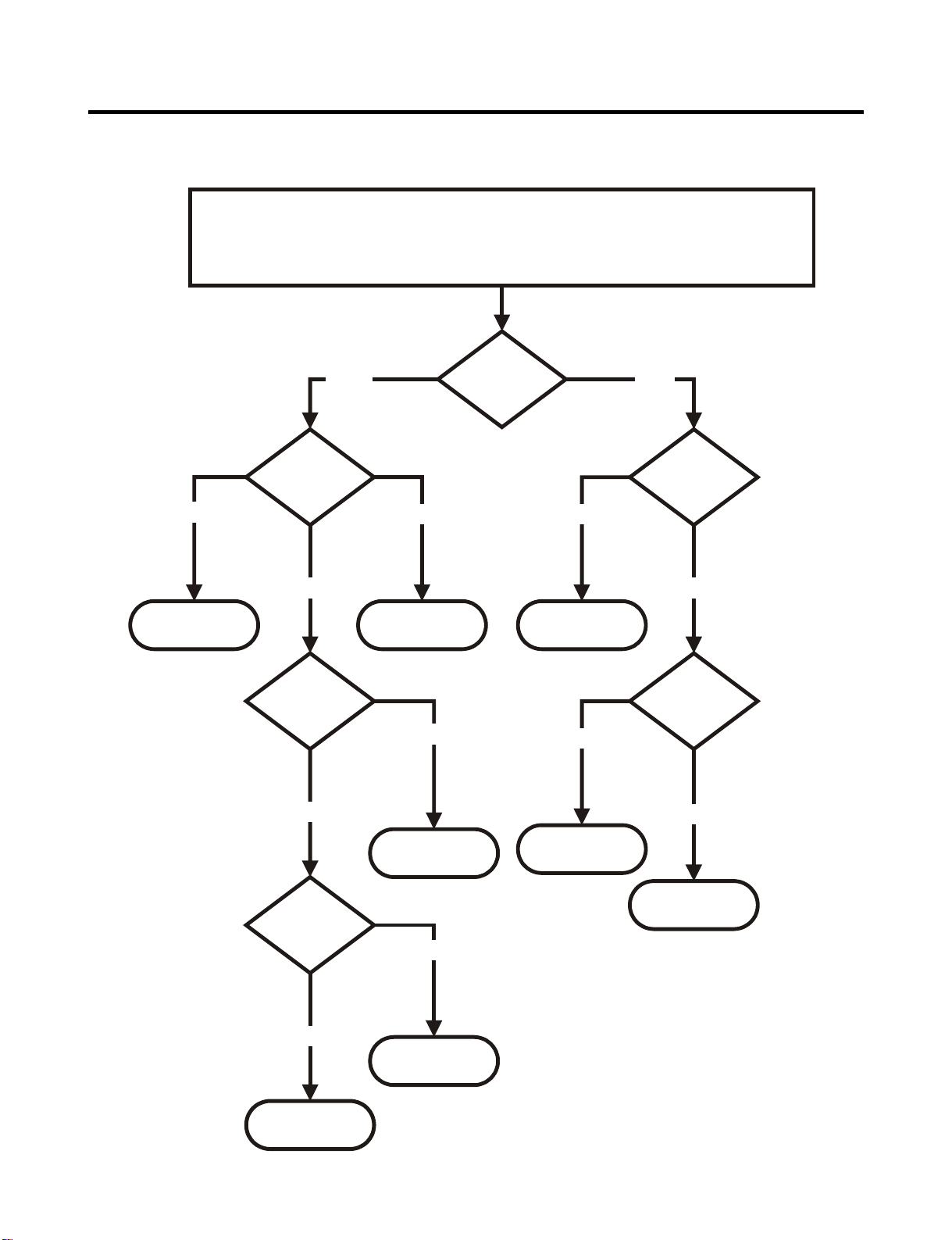
6. TROUBLESHOOTING
6-1 COMPRESSOR AND ELECTRIC COMPONENTS
1
2
Power Source.
Check
Check resistance
resistance of
of motor
motor
compressor.
compressor.
.
Remove PTC-Starter/Combo
from compressor and
measure voltage
between Terminal C of
compressor and
terminal 5 or 6 of PTC/Combo
No voltage.
Applied voltage isn't
in acceptable range.
(115V ±10%)
Check the resistance
between M-C, S-C and M-S
in motor compressor.
Check each pin to ground.
(Rated voltage
±10%)?
OLP disconnected?
Advise customer that
power supply needs to be
checked by an electrician.
Open or short
or short to
ground
Replace
compressor
YES
YES
NO
The resistance between pins should be
between 1 and 50 ohms. The resistance to
ground should be infinite.
Replace OLP.
Check connection
condition.
Reconnect.
43
2
5
5
3
5
3
4
5
Check
resistance of
PTC-Starter.
Check OLP.
Check
starting state.
Check resistance of
PTC-Starter/Combo
Check resistance of two
terminals in OLP.
Check the power supply
under load.
(Compressor attempting
to re-start after being off
for 5 minutes).
Check resistance of
two terminals in
PTC-Starter/Combo
Refer to Page 16.
Supply
voltage rating
with ±10%.
YES
Did
compressor
start?
NO
Refer to Page 16.
YES
Compressor
is OK
Replace the
compressor
NO
1
- 16 -
Page 17

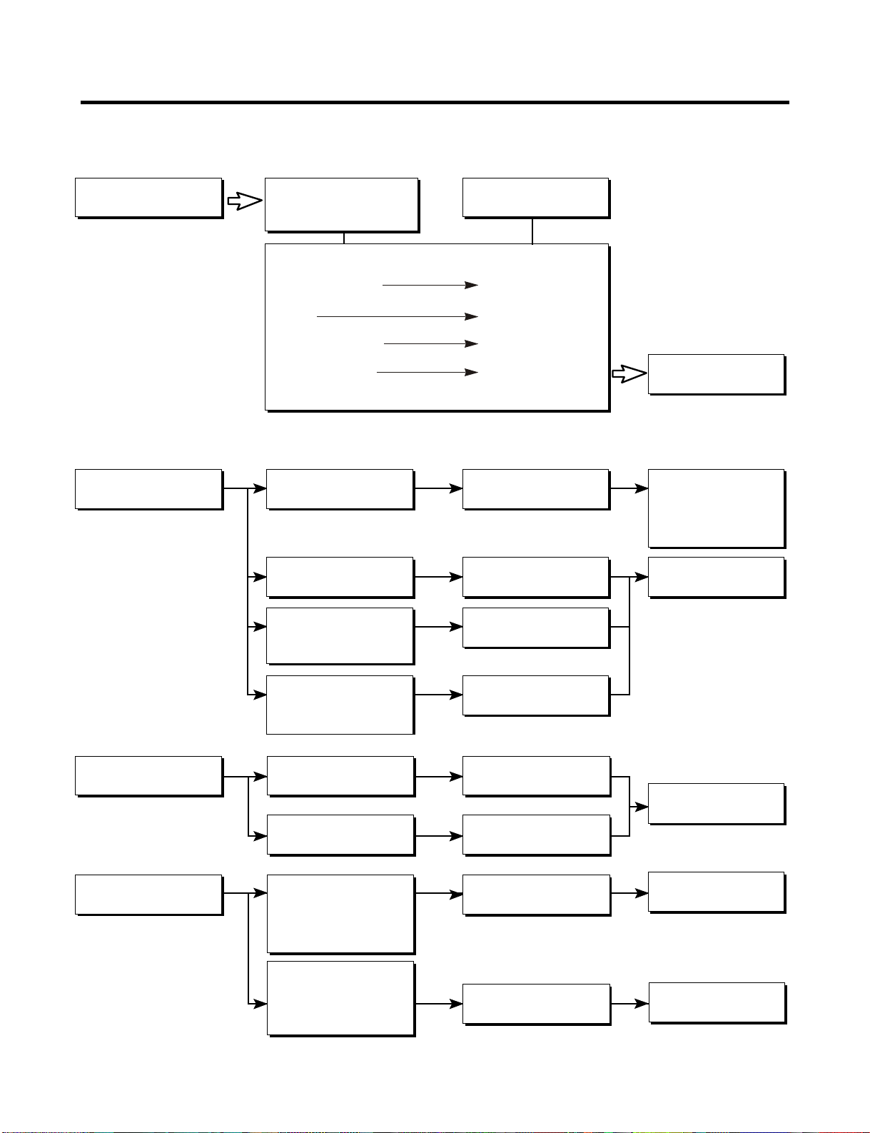
6-2 PTC / COMBO AND OLP
Normal operation of
compressor is impossible
or poor.
65
Separate PTC-Starter/Combo
from Compressor and
measure resistance
between No. 5 and 6
of PTC-Starter with a
Tester.
(Figure 19a and figure 19b)
Separate OLP from
compressor and check
resistance value between
two terminals of OLP with a
tester.
(Figure 20)
Observation value is
115V/60Hz : 6.8 ±30%
at room temperature
The resistance value
is 0 (short) or
8(open).
Shows continuity
Open
Check another
electric component.
Replace OLP.
PTC/ Combo OK
Replace PTCStarter/Combo
OLP OK
Figure 19a
?
Figure 20
Figure 19b
- 17 -
Page 18
6-3 OTHER ELECTRICAL COMPONENTS
Not cooling at all
Compressor
doesn't run
Poor cooling performance
Compressor runs
poorly
Check for open short or
incorrect resistance readings
in the following components
a. Starting devices
b. OLP
c. Compressor coil
d.Wiring harness
Check starting
voltage.
Check voltage at
starting devices.
Cause
Short, open, or broken.
Poor contact
or shorted.
Coil open or shorted.
Poor contact
or shorted.
Low voltage.
Poor or broken or
open contact.
Replace
indicated component.
Advise customer that
the power supply
needs to be checked
by an electrician.
Replace
indicated component.
Fan motor
doesn't run.
Heavy frost buildup on
evaporator
Check current flowing
In run winding of
Compressor.
Check rating of OLP.
OLP: 4TM319NFBYY
Temp. 120°C
Check wiring circuit.
13 - 15 V
Check Fan Motor.
Check current flow in
the following
components:
Sensor
Fuse-M
Check resistance flow in
the defrost heater.
Shorted.
Lack of capacity.
Wire is open or
shorted.
Coil is shorted
or open.
Open.
Open.
Replace
indicated component.
Replace
indicated component.
Replace
defrost heater.
- 18 -
Page 19
6-4 SERVICE DIAGNOSIS CHART
COMPLAINT POINTS TO BE CHECKED REMARKS
No Cooling.
Cools poorly.
Food in the
Refrigerator
is frozen.
Condensation or ice
forms inside
the unit.
Condensation forms
in the Exterior Case.
There is abnormal
noise.
•Is the power cord unplugged from the outlet?
•Check if the power switch is set to OFF.
•Check if the fuse of the power switch is shorted.
•Measure the voltage of the power outlet.
•Check if the unit is placed too close to the wall.
•Check if the unit is placed too close to the stove,
gas cooker, or in direct sunlight.
•Is the ambient temperature too high or
the room door closed?
•Check if food put in the refrigerator is hot.
•Did you open the door of the unit too often
or check if the door is sealed properly?
•Check if the Control is set to Warm position
•Is food placed in the cooling air outlet?
•Check if the control is set to colder position.
•Is the ambient temperature below 5°
•Is liquid food sealed?
•Check if food put in the refrigerator is hot.
•Did you open the door of the unit too
Often or check if the door is sealed properly?
•Check if the ambient temperature and humidity
of the surrounding air are high.
•Is there a gap in the door gasket?
•Is the unit positioned in a firm and even place?
•Are any unnecessary objects placed
Behind side of the unit?
•Check if the Drip Tray is not firmly attached.
•Check if the cover of the compressor enclosure
in the lower drip tray taken out.
C?
•Plug into the outlet.
•Set the switch to ON.
•Replace the fuse.
•If the voltage is low, correct the wiring.
•Place the unit about 4 inches (10 cm) from the wall.
•Place the unit away from these heat sources.
•Lower the ambient temperature.
•Put in foods after they have cooled down.
•Don't open the door too often and close
it firmly.
•Set the control to Recommended position .
•Place foods in the high-temperature section.
(front part)
•Set the control to Recommended position .
•Set the control to
•Seal liquid foods with wrap.
•Put in foods after they have cooled down.
•Don't open the door too often and close
It firmly.
•Wipe moisture with a dry cloth. It will disappear
in low temperature and humidity.
•Fill up the gap.
•Adjust the leveling screw, and position the
refrigerator in a firm place.
•Remove the objects.
•Fix the drip tray firmly in the original position.
•Place the cover in its original position.
Warm position
.
Door does not
close well.
Ice and foods
smell unpleasant.
Other possible problems:
Check if frost forms in
the freezer.
Check the
refrigeration system.
Check the thermistor
•Check if the door gasket is dirty with
an item like juice.
•Is the refrigerator level?
•Is there too much food in the refrigerator?
•Check if the inside of the unit is dirty.
•Are foods with a strong odor unwrapped?
•The unit smells of plastic.
Not
defrosting
The system
is faulty.
The operation of
the thermistor is
incorrect.
•Clean the door gasket.
•Position in a firm place and level the
leveling screw.
•Make sure food stored in shelves does not prevent
the door from closing.
•Clean the inside of the unit.
•Wrap foods that have a strong odor.
•New products smell of plastic, but this
will go away after 1-2 weeks.
Check components
of the defrosting
circuit.
Perform sealed
system repair.
Check the thermistor
- 19 -
Page 20
6-5 REFRIGERATION CYCLE
* Troubleshooting Chart
CAUSE
PARTIAL
LEAKAGE
LEAKAGE
COMPLETE
LEAKAGE
R
E
S
CLOG
T
RC
I
T
I
O
CLOG
N
MOISTURE
RESTRICTION
C
NI
O
E
LOW
F
M
F
COMPRESSION
P
I
C
R
I
E
E
S
NO
N
S
T
COMPRE-
OR
SSION
STATE OF
THE UNIT
Freezer
compartment and
refrigerator don’t
cool normally
Freezer
compartment and
refrigerator don’t
cool normally
Freezer
compartment and
refrigerator don’t
cool normally
Freezer
compartment and
refrigerator don’t
cool.
Cooling operation
stops periodically.
Freezer and
refrigerator don’t
cool.
No compressing
operation.
STATE OF THE
EVAPORATOR
Low flowing sound of
refrigerant is heard and frost
forms in inlet only.
Flowing sound of refrigerant
is not heard and frost isn’t
formed.
Flowing sound of refrigerant
is heard and frost forms in
inlet only.
Flowing sound of refrigerant is
not heard and frost isn’t
formed.
Flowing sound of refrigerant is
not heard and frost melts.
Low flowing sound of
refrigerant is heard and frost
forms in inlet only.
Flowing sound of refrigerant is
not heard and there is no
frost.
TEMPERATURE
OF THE
COMPRESSOR
A little higher than
Room
temperature.
Equal to room
temperature.
A little higher than
Room
temperature.
Equal to room
temperature.
Lower than room
temperature.
A little higher than
Room
temperature.
Equal to room
temperature
REMARKS
- Refrigerant level is low due to a
leak.
¥
- Normal cooling is possible by
restoring the normal amount of
¥
refrigerant and repairing the leak.
¥
- No discharging of refrigerant.
- Normal cooling is possible by
restoring the normal amount of
¥
refrigerant and repairing the leak.
¥
- Normal discharging of the
refrigerant.
¥
- The capillary tube is faulty.
- Normal discharging of the
refrigerant.
¥
- Cooling operation restarts when
heating the inlet of the capillary
¥
tube.
¥
- Low pressure at high side of
compressor due to low
¥
refrigerant level.
¥
- Nopressure in the high pressure
part of the compressor.
¥
¥
- 20 -
Page 21
6-5-1 SEALED SYSTEM DIAGNOSIS
All components operating, No airflow problems, Not frosted up as a defrost problem
Problem has been isolated to sealed system area
Not Cooling Complaint
Very Fast
Inefficient
Compressor
Partial
Equalization
Test
Fast
Condenser
Temperature
Room Temperature
Pattern?
Partial
Restriction
Hotter than Normal
Frost
None
Equalization
Test
Very SlowVery Slow
Very Fast
Complete
Restriction
Cap Tube
Sound
Faint
None to Weak
Air/Low Side
Leak
Trace of Oil
Yes
No
Leak
Undercharge
(The equalization test is trying to restart a compressor after it has been operating.)
Loss of Change
Compressor Not
Pumping
- 21 -
Page 22

6-6 Troubleshooting with Error
Freezer Sensor Error
CON5
Main PCB
Is Er-FS displayed?
Is the connection loose?
11
12
No
BL
BL
Yes
Yes
F-Sensor
Wiring diagram
Reconnect
Power Off (to protection of MICOM)
& disconnect CON5 and check the
resistance values between pins 11
& 12 (BL to BL).
Pin 11
Pin 12
Test Point Result
Pin 11 to
Pin 12
Reconnect CON5 and Power ON
•ÄKÑW
•ž$Ñ
Yes
No
Replace
F - sensor
If the Er-FS appears,
replace the main PCB.
Otherwise, explain to
the customer!
- 22 -
Page 23

Refrigerator Sensor Error
CON5
Main PCB
Is Er-rS displayed?
Is the connection loose?
9
10
No
WH
WH
Yes
Yes
R-Sensor
Wiring diagram
Reconnect
Power Off (to protection of MICOM)
& disconnect CON5 and check the
resistance values between pins 9
& 10 (WH to WH).
Pin 9
Pin 10
Test Point Result
Pin 9 to
Pin 10
Reconnect CON5 and Power ON
•ÄK÷
•ž$Ñ
Yes
No
Replace
R - sensor
If the Er-rS appears,
replace the main PCB.
Otherwise, explain to
the customer!
- 23 -
Page 24

Defrost Sensor Error
CON5
Main PCB
Is Er-dS displayed?
Is the connection loose?
7
8
No
BO
BO
Yes
6
1
2
7
Housing-A
Yes
D-Sensor
BO
BO
Wiring diagram
Reconnect
Power Off (to protection of MICOM)
& disconnect CON5 and check the
resistance values between pins 7
& 8 (BO to BO).
Pin 8
Pin 7
Test Point Result
Pin 7 to
Pin 8
Reconnect CON5 and Power ON
•Ánô
•ÁHÎz
Yes
No
Retire the back
panel of the freezer
compartment, and
identify the
connection of DSensor (Housing A),
Is the connection
loose?
If the Er-dS appears,
replace the main PCB.
Otherwise, explain to
the customer!
Yes
No
Reconnect
Replace
D - sensor
- 24 -
Page 25

Room Temp Sensor Error
CON7
Main PCB
Is Er-dS displayed?
Is the connection loose?
No
Power Off (to protection of MICOM)
& disconnect CON5 and check the
resistance values between pins 5
& 6 (BN to BN).
5
6
BN
BN
Yes
Yes
No
Rt-Sensor
Wiring diagram
Reconnect
Replace
Rt - sensor
Pin 5
Pin 6
Test Point Result
Pin 5 to
Pin 6
Reconnect CON5 and Power ON
•Ánô
•ÁHÎz
Yes
- 25 -
If the Er-rt appears,
replace the main PCB.
Otherwise, explain to
the customer!
Page 26

Freezer Fan Error
Main
PCB
Is Er-FF displayed?
Yes
Is the connection loose?
Yes
No
Reset and
Enter the TEST 1 MODE
Is the output voltage between pin 1
and pin 2 of CON4 like as below?
Pin 1
Pin 2
CON4
No
WH
1
GY
2
PR
3
Reconnect
Replace
Main PCB
1
2
3
Housing
BK
1
RD
2
PR
3
Does the cold-air come out
of the top of the main duct?
Is the feedback voltage between
pin 2 & pin 3 of CON4 like as
below?
(from motor to main board)
F-FAN
Yes
Wiring diagram
No
Pin 2
Pin 3
No
See next page
Replace
Main PCB
Freezer Fan Voltages
Test Point
Pin 1 to
Pin 2
Yes
Result
12~
16 V
Feedback Voltages
- 26 -
Test Point
Pin 2 to
Pin 3
Yes
Explain to the customer!
Result
1~
4 V
Page 27

Freezer Fan Error
Disassembly the back panel
of the Freezer compartment,
and identify the connector of
the freezer fan, is the
connection loose?
No
Replace PCB.
If the Er-FF appears,
replace the main PCB.
Otherwise, explain to
the customer!
Yes
Reconnect
- 27 -
Page 28

Defrost Heater Error
Is Er-dH displayed?
Yes
Are the connections loose?
CON5
D-Sensor
Yes
BO
BO
Reconnect
1
6
7
2
Housing- A
BO
BO
7
8
CON5
CON2
CON1
BN
1
3
BL
RD
1
6
7
1
2
BK
3
BK
2
BN
FUSE-M
DEF-Heater
Wiring diagram
RESET TEST 3 MODE
Is the voltage value between
0 ~ 2 V AC
CON1
CON2
PIN3
Yes
Disassembly the back panel of the
freezer compartment and identify
the connector of the Defrost Heater
and Defrost Sensor. Are this
connectors loose?
PIN1
No
No
Replace
Main PCB
Check Def.
Heater
CON2
No
Enter the TEST 3 MODE
Is the voltage value between CON2 pin1
(BN) and CON1 pin3 (BL) 115V AC?
CON1
PIN3
CON2
PIN1
No
Yes
Replace
MAIN PCB
- 28 -
Yes
Reconnect
Page 29

Defrost Heater Error
Check Def. Heater
Yes
Check the continuity
between pins 1 & 2 on
M-Fuse.
PIN1
PIN2
Yes
Check the resistance
value between pin 1 & 3
on Defrost Heater
No
No
Replace M-Fuse
Replace Def. Heater
Is the resistance value of DEF-sensor like as below?
It depends on the temperature.
Defrost Sensor Resistance
Test
Point
- 30°
- 20°
- 10°
Replace
DEF-sensor
Explain to the customer!
: It can be occurred, when the gasket is not stuck
to roduct or when you put the high temperature
loads (hot foods) a lot in the product.
0°
Result
•PÖ\•
•¥Q×]
•¥Q×]
••
No
Test
Point
10°
20°
30°
40°
Result
•”@ÆL
•Üb•
•Ü‰•
•Ü‰•
Yes
Test Point
pin1 to pin3
Result
•!§TÚ†
•!§T
Yes
Check D-Sensor
- 29 -
Page 30

ICEMAKER OPERATING PRINCIPLES AND REPAIR
7.
7-1 OPERATION PRINCIPLE
7-1-1 Operation Principle of Icemaker
Power On
Start Position
Icemaking
Mode
Harvest
Mode
Fill
Park Position
Test Mode
Adjust Ejector to Start Position with power on.
•
•
Wait until water becomes cold after starting the
Icemaking operation.
• Run MOTOR to drop ice from the tray into the ICE BIN.
• Perform Icemaking Mode after supplying water by operating
the SOLENOID in ICE VALVE.
• With the detect lever, checks if the ICE BIN is full.
• To operate LINE and SERVICE, press and hold the Cube Size button
for 3 seconds. The icemaking will run through 3 stages:
Harvest Fill Icemaking.
1. Turning the Icemaker stop switch off (O) stops the icemaking function.
2. Setting the Icemaker switch to OFF and then turning it back on will reset the icemaker control.
Cube Size button
Power (On/Off) Switch
- 30 -
Page 31

7-2 ICE MAKER FUNCTIONS
7-2-1 Ice Making Mode
1. Icemaking refers to the freezing of supplied water in the ice trays. Complete freezing is assured by measuring the
temperature of the Tray with icemaking SENSOR.
2. Icemaking starts after completion of the water fill operation.
3. The icemaking function is completed when the sensor reaches -7°C, 60 to 240 minutes after starting.
NOTE :After icemaker power is ON, the icemaker heater will be on for test for 9 sec.
7-2-2 Harvest Mode
1. Harvest (Ice removing) refers to the operation of dropping ices into the ice bin from the tray when icemaking has
completed.
2. Harvest mode:
(1) The Heater is ON for 30 seconds, then the motor starts.
(2) Harvest mode is completed if it reaches start position again while Heater & Motor are on at the same time.
A. ice bin is full : The EJECTOR stops (heater off).
B. ice bin is not full : The EJECTOR rotates twice to open for ice.
NOTE :If the EJECTOR does not rotate once within 5 minutes in status (2), separate heater control mode starts
operating to prevent the EJECTOR from being constrained. (It is recommended that the user open for ice to
return to normal mode.)
7-2-3 Fill/Park Position
1. Once a normal harvest mode has been completed, the water solenoid will be activated.
2. The amount of water is adjusted by pressing the fill key repeatedly. This changes the time allowed for fill as illustrated in
the table below.
Water supply amount table
STAGE TIME TO SUPPLY INDICATIONS REMARKS
1
2
3
6 sec.
7 sec.
8 sec.
The water amount will vary depending
on the water control switch setting, as
well as the water pressure of the
connected water line.
- 31 -
Page 32

7-2-5 Function TEST
1. This is a compulsory operation for test, service, cleaning, etc. It is operated by pressing and holding the Cube Size button for 3 seconds.
2. The test works only in the Icemaking Mode. It cannot be entered from the Harvest or Fill mode. (If there is an ERROR, it
can only be checked in the TEST mode.)
3. Caution! If the test is performed before water in the icemaker is frozen, the ejector will pass through the water. When the fill
mode begins (Stage 4), unless the water supply has been shut off, added water will overflow into the ice bin. If the control
Doesn’t operate normally in the TEST mode, check and repair as needed.
4. After water is supplied, the normal CYCLE is followed: icemaking Harvest Fill Park Position
5. Five seconds after Stage 5 is completed, the icemaker returns to MICOM control. The time needed to supply water
resets to the pre- test setting.
Diagnosis TABLE
STAGE ITEMS INDICATOR REMARKS
1
2
3
4
5
6
HEATER
MOTOR
HALL IC
(TRAY)
SOLENOID VALVE
HALL IC
(LEVER)
Reset
Return to Status prior to
TEST MODE
*
Five seconds after heater starts, heater will
go off if temperature recorded by sensor is
10°C (50°F)or lever is in up position.
Five seconds after heater starts, you can
confirm that motor is moving.
You can confirm Hall IC detection of position.
Two seconds after detection of initial
position, you can confirm that valve is on.
You can check when the Hall IC is sensing a full
ice condition. (If there is a water fill error, the
fifth LED is not on.)
Five seconds after fifth stage is completed,
the icemaker resets to initial status.
7-3 DEFECT DIAGNOSIS FUNCTION
7-3-1 ERROR CODES shown on Ice Maker water supply control panel
NO DIVISION INDICATOR REMARKS
1
2
3
* ERROR indicators in table can be checked only in TEST mode.
Normal
Icemaking
Sensor
malfunction
Icemaker Kit
malfunction
Note fill times
(see previous page)
Open or shorted wire or sensor
Ejector blades have not reached
the park position after 18
minutes from start of harvest
mode
- 32 -
PROBLEM
None
Display switch
operates properly
Make sure that the wire
on each sensor is
connected.
Check
HALL IC/MOTOR/
HEATER/RELAY
Page 33

8.WATER FILTER
8.1 WATER FILTER CARTRIDGE REPLACEMENT
FILTER (on some models)
It is recommended that you replace the filter when the
water filter indicator light turns on or your water dispenser
or ice maker decreases noticeably.
After changing the water filter cartridge, reset the water
filter status display and indicator light by pressing and
holding the BUTTON for 3 seconds.
How to change the old cartridge.
1. Turn the shut off valve off (house valve)*
2. Dispense water from the system to empty the tubing
(approximately for 50 seconds).*
Pull out the cartridge.
4. Replace with a new cartridge.
Take the new cartridge out of its packaging and remove
protective cover from the o-rings.
With cartridge knob in the vertical position, push the new
filter cartridge into the cover until it stops.
3. Remove the old cartridge.
Rotate the knob of the cartridge counter clockwise.
When the cartridge is removed, it will click out of place.
NOTE: There will be water in the cartridge. Some spilling
may occur through the hole at rear bottom side of cover.
You may use a cup or something like that to prevent spilt
water drop into food.
If you can´t turn the filter from side to side, it isn´t fully
inserted. Push it in firmly and twist it into place. You will
hear it click into place.
Using its handle, twist the cartridge clockwise about 1/4
turn. You will hear when it clicks into place.
- 33 -
Page 34

5. Turn the shut off valve on (house valve)*
NOTE: To purchase replacement water filter
cartridges, visit your local appliance dealer or
part distributor.
6. Flush water out from the system until air gets eliminated
and water start to dispense (approximately for 60
seconds).*
8.2 WATER DISPENSER (on some models)
1. Push up the dispenser switch with a cup until you hear
click to get cold water.
Try can be easily removed by pressing and pull in git.
*Steps 1, 2, 5 & 6 only for models with water dispenser.
2. Tilt up the front of tray slightly and snap the ribs in the
holes to replace the tray.
Important: If no water dispensed when the refrigerator is
first installed, there may be air in the water line system.
Press the dispenser switch for at least two minutes to
remove trapped air from the water line and to fill the
water system.
- 34 -
Page 35

9. DESCRIPTION OF FUNCTION & CIRCUIT OF MICOM
9-1 FUNCTION
9-1-1 Function
1. When the appliance is plugged in, it is set to “37” for Refrigerator and “0” for freezer.
You can adjust the Refrigerator and the Freezer control temperature by pressing the ADJUST button.
2. When the power is initially applied or restored after a power failure, it is automatically set to “37” & “0”.
9-1-2 How to Change the Temperature Mode to °F / °C
1. The setting temperature mode can be changed to °F / °C by pressing and holding Freezer Temp. key of Freezer and
Refrigerator Temp. key of Refrigerator over 5 seconds at the same time.
2. The initial setting is °F. Whenever the mode is changed, the LED lights are changed.
9-1-3 Lock function (dispenser and display button lock)
1. In power application of refrigerator, the “LOCK” icon is turned off at the
upper side of lock graphic of display with the lock release status.
2. If desiring to lock the display the dispenser and control panel push on
the LOCK button more than 3 seconds. LOCK text is turned on at the
upper side of lock graphic of display with lock status.
3. The buzzer sound and control panel and dispenser function is not
performed even if pressing display button other than lock key in the
lock status.
4. If desiring to release the lock status and pressing the lock button more
than 3 seconds. “LOCK” icon is turned off at the upper side of lock graphic of display with the lock release status.
Ex) In selecting
"LOCK"
Ex) In selecting
9-1-4 Filter condition display function
1.There is a replacement indicator icon for the water
filter cartridge on the dispenser.
2. Water filter needs replacement once six months or
Classification
In initial Power On
/ Filter RESET
about 28,000 seconds of using water filter.
3. Water filter light turns on to tell you need to replace
the filter soon.
Filter Status
Display
4. After replace the filter, press and hold the Filter Reset
Button more than 3 seconds.
Then water filter icon turns off with reset status.
"LOCK" again
Replace indicator
light on
9-1-5 Ultra Ice selection
Please select this function for prompt freezer.
• Function is repeated following below whenever pressing Ultra Ice button.
• Ultra Ice function automatically turns off if a fixed time passes.
- 35 -
Page 36

9-1-6 Control of freezer fan motor
1. Freezer fan motor has high and standard speeds.
2. High speed is used at power-up, for Ultra Ice, and when refrigerator is overloaded.
Standard speeds is used for general purposes.
3. To improve cooling speed, the RPM of the freezer fan motor change from normal speed to high.
4. High speed (2700RPM) : Initial power on or load corresponding operation, Ultra Ice.
Normal speed (2400RPM) : General working conditions.
5. Fan motor stops when refrigerator or freezer door opens.
9-1-7 Ultra Ice
1. The purpose of this function is to intensify the cooling speed of freezer and to increase the amount of ice.
2. When Ultra Ice is selected, LED will remain ON for Ultra Ice Cycle.
3. If power is lost to the refrigerator, Ultra Ice function will be canceled.
4. To activate this function, to press the Ultra Ice key and the LED will turn ON. This function will remain activated for 24 hrs.
The first three hours the compressor and Freezer Fan will be ON. The next 21 hours the freezer will be controlled at the
lowest temperature. After 24 hours or if the Ultra Ice key is pressed again, the freezer will return to its previous
temperature.
5. For the first three hours notice the following cases:
(1) Compressor and freezer fan (HIGH RPM) continuously operate for three hours.
(2) If defrost starts during Ultra Ice, Ultra Ice operates for the rest of time after defrost is completed, when Ultra Ice
operation time is less than 90 minutes.
If Ultra Ice operates for more than 90 minutes, the Ultra Ice will operate for two hours after defrost is completed.
(3) If Ultra Ice is pressed during defrost, Ultra Ice LED is on but this function will start seven minutes after defrost is
completed and it shall operate for three hours.
(4) If Ultra Ice is selected within seven minutes after compressor has stopped, the compressor (compressor delays seven
minutes) shall start after the balance of the delay time.
(5) The fan motor in the freezer compartment runs at high speed during Ultra Ice .
6. For the rest of the 21 hours, the freezer will be controlled at the lowest temperature.
9-1-8 Refrigerator lamp auto off
1. To avoid heat damage caused by the lamp, it is turned off automatically when the refrigerator door is open for more than 7
minutes.
9-1-9 Alarm for Open Door
1. This feature sounds a buzzer when the freezer or refrigerator door is not closed within 1 minute after it is opened.
2. One minute after the door is opened, the buzzer sounds three times each for 1/2 seconds. These tones repeat every 30
seconds.
3. The alarm is cancelled when the freezer or the refrigerator is closed while the buzzer sounds.
Freezer Door
or Refrigerator
Door
Buzzer
Closed Open Closed Open
3 Times 3 Times 3 Times 3 Times
30 sec 30 sec 30 sec
Within 1 min. 1 min.
Closed
- 36 -
Page 37

9-1-10 Buzzer Sound
When the button on the front Display is pushed, a Ding~ Dong~ sound is produced.
9-1-11 Defrost cycle
1. A defrost cycle will be initiated after 4 hours of accumulated compressor run time after the initial power up or a power
failure.
2. After the initial defrost, the defrost cycle is initiated after 7 hours of accumulated compressor run time.
3. The defrost cycle will be terminated once the defrost sensor reaches 46°F(8°C).
9-1-12 Filter Replacement Indication
1. In 6 months after the UNIT (refrigerator) is power on, or after 28,000 seconds of dispenser use, the water filter icon is ON.
2. When the water filter indicator LED is illuminated, you should change the water filter. After this, you must press the water
filter button for three seconds and you will hear a ding-dong sound.
The icon will be OFF. This operation will indicate that the UNIT is reset to its initial conditions, so this process is restarted.
9-1-13 Dispenser light
Please select this function for DISPENSER LIGHT MODE.
1. Normal status (LIGHT icon is OFF) : When dispenser is operated, DISPENSER LIGHT is ON.
2. ON status (LIGHT icon is ON) : DISPENSER LIGHT is on continuously
- 37 --
Page 38

9-1-14 Automatic Diagnosis Function
1. Automatic diagnosis makes servicing the refrigerator easy.
2. When an error occurs, the buttons will not operate; but the tones. such as ding. will sound.
3. When the error CODE removes the sign, it returns to normal operation (RESET).
4. The error CODE shows on the Refrigerator and Freezer Display.
ERROR CODE on display panel
“Er rt” only available in LED
check function**
**LED check function: Press simultaneously “Ultra Ice” and “Freezer Temp” buttons for one second or longer, every LED
on the display turns on. When the buttons are released the previous mode is restored.
- 38 --
Page 39

9-1-15 TEST Mode
1. The Test mode allows checking the PCB and the function of the components as well as finding out the defective part in
case of an error.
2. The test mode is operated by pressing two buttons at Display panel.
3. While in the test mode, the function control button is not recognized, but the recognition tone (beep~) sounds.
4. After exiting the test mode, be sure to reset by unplugging and then plugging in the appliance.
5. If an error, such as a sensor problem, is detected while in the test mode, the test mode is cleared and the error code is
displayed.
6. While an error code is displayed, the test mode will not be activated.
OPERATION
Maximum test time:
5 minutes
Maximum test time:
5 minutes
Maximum test time: 1 hour
* Demonstration MODE:
1. Open any door to enter to this mode.
2. Press the Ultra Ice button and Refrigerator Temp button simultaneously for more than 5 seconds.
3. The display shows the Demo graphic. (The word “OFF” appears on the display)
4. In this status all loads are OFF (Compressor/ Fan/ Damper/ Heater)
(Even is Demonstration Mode. The refrigerator lamp automatic off function works normally and can be
demonstrated).5. Exit Demonstration mode and reset Display by pressing Ultra ice button and Refrigerator Temp
button simultaneously for more than 5 seconds.
- 39 -
Page 40

9-2 PCB FUNCTION
9-2-1 Power Circuit
POWERPOWER
CON1CON1
BD1BD1
D3SBA60D3SBA60
R3R3
CE1CE1
CM2CM2
L2L2
32mH/0.5A32mH/0.5A
FUSE1FUSE1
250V/2A250V/2A
L1L1
2mH/7A2mH/7A
CM1CM1
470nF470nF
275VAC275VAC
1111
VA1VA1
R2R2
560KJ560KJ
1/2W1/2W
R1R1
44
IC2IC2
STRSTR
G6351G6351
56KJ56KJ
47uF47uF
2W2W
/450V/450V
44
11
33
22
55
33
R4R4
6.8KJ6.8KJ
D1D1
FB1FB1
FR107FR107
D2D2
FR107FR107
CE2CE2
22uF22uF
IC3-1IC3-1
R6*R6*
680J680J
CC1CC1
471471
/630V/630V
CM3CM3
473473
RocpRocp
TRANSTRANS
11
22
R5*R5*
55
47J47J
44
99
CC2CC2
221/400V221/400V
D3D3
12V12V
RL2RL2
1010
+15.5V+15.5V
1212
D4D4
RL2RL2
CE4CE4
680uF680uF
/35V/35V
88
680uF680uF
/25V/25V
R7*R7*
1KJ1KJ
R8*R8*
10KJ10KJ
CE3CE3
IC4IC4
KIA431KIA431
IC3IC3
CM4CM4
104/50V104/50V
RL1*RL1*
9.1KF9.1KF
RL2*RL2*
2.4KF2.4KF
IC1 IC1
MICOMMICOM
IC5IC5
78057805
CC3CC3
104104
5V5V
2222
VDD VDD
VarefVaref
4242
CE5CE5
220uF220uF
/16V/16V
CC5*CC5*
104104
2121
VssVss
VassVass
1717
TESTTEST
CC4CC4
104104
The secondary part of the TRANSFORMER is composed of the power supply for the display, the BLDC FAN Motor drive
(15.5 V), the relay drive (12 Vdc) and the MICOM and IC (5 Vdc).
The voltage for each part is as follows:
PART VA 1 CE 3 CE 4 CE 5
VOLTAGE 115 Vac 12 Vdc 15.5 Vdc 5 V
VA1 is a part for preventing over voltage and noise. When 385V or higher power is applied, the inside elements are shortcircuited and broken, resulting in blowout of the fuse in order to protect the elements of the secondary part of the
TRANSFORMER.
- 40 -
Page 41

9-2-2 Oscillation Circuit
CSTM400G53-A0
This circuit generates the base clock for calculating time and the synchro clock for transmitting data from and to t
logic elements of the IC1 (MICOM). Be sure to use specified replacement parts, since calculating time by the IC1 may be
changed. If changed, the OSC1 SPEC will not work.
he inside
9-2-3 Reset Circuit
The RESET circuit allows all the functions to start at the initial conditions by initializing various parts, including the RAM
inside the MICOM (IC1) when the power is initially supplied or the power supply to the MICOM is restored after a
momentary power failure. For the initial 10ms of power supply, LOW voltage is applied to the MICOM RESET terminal.
During a normal operation, 5V is applied to the RESET terminal. (If a malfunction occurs in the RESET IC, the MICOM will
not operate.)
- 41 -
Page 42

9-2-4 Load / Buzzer Drive & Open Door Detection Circuit
1. Load Drive Condition Check
L1L1
2mH/7A2mH/7A
CM1CM1
470nF470nF
COMPCOMP
FUSE-M FUSE-M
ncnc
ncnc
ncnc
ncnc
275VAC275VAC
VA1VA1
77
55
33
RY1RY1
OLPOLP
11
CON2CON2
11
comcom
33
comcom
55
comcom
comcom
77
DHIU/OMIHDHIU/OMIH
RY2RY2
G5NB-1AG5NB-1A
RY3RY3
G5NB-1AG5NB-1A
RY4RY4
DHIU/OMIHDHIU/OMIH
RY5RY5
G5N-1AG5N-1A
CON3CON3
55
RY6RY6
G5N-1AG5N-1A
33
11
ICE MAKERICE MAKER
POWERPOWER
STARTING CAPACITORSTARTING CAPACITOR
DEF-HEATERDEF-HEATER
LAMP-FLAMP-F
LAMP-RLAMP-R
FRENCH DOOR FRENCH DOOR
HEATERHEATER
CON1CON1
1111
99
RUNNING CAPACITORRUNNING CAPACITOR
PTC STARTPTC START
AA
BB
DOOR S/W-FDOOR S/W-F
CC
DD
DOOR S/W-R1&R2DOOR S/W-R1&R2
MM
WATER VALVEWATER VALVE
MM
VALVE IIVALVE II
D7D7
1N40041N4004
D10D10
1N40041N4004
IC6*IC6*
KID65003AFKID65003AF
1616
1111
1212
1313
1414
1515
99
11
66
55
44
33
22
88
99
P07P07
1414
P02P02
1313
P03P03
1212
P04P04
IC1 IC1
(MICOM)(MICOM)
1111
P05P05
1010
P06P06
FRENCH DOOR
HEATER
DEW HEATER
CON3 PIN3
LOAD TYPE
Measurement Location
ON
Condition
OFF
COMP
CON1 PIN1
DEFROSTING
HEATER
CON2 PIN1
F LAMP R LAMP
CON2 PIN3 CON2 PIN5
115V
1V or below
Note:
To measure outputs of the control board, check voltages between each Measurement Location
and CON1 PIN 3 (neutral).
- 42 -
VALVE
CON2 PIN7
Page 43

2. Motors driving circuit
2.1 Fan motor driving circuit (freezing compartment fan)
1. This circuit makes standby power 0 by cutting of power supplied to ISs inside of the fan motor in the fan motor OFF
2 This is a circuit to perform a temporary change of speed for the fan motor and applies DC voltage up to 7.5V ~ 16V to motor.
3. This circuit prevents over-driving the fan motor by cutting of power applied to the fan motor in the lock of fan motor by
sensing the operation RPM of the fan motor.
part part part
a b
MOTOR OFF 2V or less 0V 5V
MOTOR ON 13V~16V 0V 2V~3V
c
2.2 Cooling motor driving circuit (machine room)
1. This circuit makes standby power 0
by cutting off power supplied to ISs inside of the fan motor in the fan motor OFF
.
2. This is a circuit to perform a temporary change of speed for the fan motor and applies DC voltage up to 7.5V ~ 16V to motor
Part part
a b
MOTOR OFF 2V or less 0V
MOTOR ON 13V~16V 0V
CC19*
223
4.7KJ
CON4
A
4
3
4
5
1
C-FAN
R46
6
CC20*
102
I C 1
(MICOM)
P14
P11
(INT1)
R43
Q4
330J
KTB1151
R40
4.7KJ
R41
35
(PPG)
32
3.9KJ
R42*
10KJ
RJ1*
R44
1.5KJ
1/2W
Q5
KTC3198
D8
FR107
L4
1mH
220uF
/25V
CE12
D9
FR107
R45
2KJ
- 43 -
Page 44

3. Open Door Detection Circuit Check
Measurement
Freezer/
Location
Refrigerator Door
Closed 5 V
Open 0 V
7
1
2
(PIN NO.30 & PIN NO.37)
9-2-5 Temperature Sensor Circuit
7
5
6
The upper CIRCUIT reads REFRIGERA
TOR temperature, FREEZER T
for defrosting and the indoor temperature for compensating for the surrounding temperature into MICOM.
OPENING or SHORT state of each TEMPERATURE SENSOR are as follows:
SENSOR CHECK POINT NORMAL (-30°C ~ 50°C)
Freezer Sensor POINT Voltage
A
emperature, and DEFROST-SENSOR temperature
SHORT-CIRCUITED
OPEN
Refrigerator Sensor POINT Voltage
Defrosting Sensor POINT Voltage
Room Temperature sensor
POINT Voltage
B
C
D
0.5 V ~ 4.5 V 0 V 5 V
- 44 -
Page 45

9-2-6 Refrigeration Compartment Stepping Motor Damper Circuit
* The circuit shown below is the damper circuit to regulate the refrigerator temperature.
2
4
3
9-2-7 Dispenser Input
7
3
4
- 45 -
Page 46

9-2-8 Temperature Compensation & Overcooling/Undercooling Compensation Circuit
1. Refrigerator Temperature Compensation
Refrigerator
Resistance Temperature Remark
(RCR) Compensation
180 K +2.5°C Compensation by
56 K +2.0°C
33 K +1.5°C
18 K +1.0°C
12 K +0.5°C
10 K 0 °C
8.2 K -0.5
5.6 K -1.0
3.3 K -1.5
2 K -2.0
470 -2.5°C
2. The temperature compensation for refrigerator compartment is in the following table:
Revised resistance
Present resistance
470 change Up Up Up Up Up Up Up Up Up Up
2k Down Change Up Up Up Up Up Up Up Up Up
3.3k Down Down Change Up Up Up Up Up Up Up Up
5.6k Down Down Down Change Up Up Up Up Up Up Up
8.2k Down Down Down Down Change Up Up Up Up Up Up
Refrigerator 2.5°C 2°C 1.5°C 1°C 0.5°C No 0.5°C 1°C 1.5°C 2°C 2.5°C
(RCR) 10k Down Down Down Down Down Change Up Up Up Up Up
12k Down Down Down Down Down Down Change Up Up Up Up
18k Down Down Down Down Down Down Down Change Up Up Up
33k Down Down Down Down Down Down Down Down Change Up Up
56k Down Down Down Down Down Down Down Down Down Change Up
180k Down Down Down Down Down Down Down Down Down Down Change
470 2k 3.3k 5.6k 8.2k 10k 12k 18k 33k 56k 180k
No 0.5°C 1°C 1.5°C 2°C 2.5°C 3°C 3.5°C 4°C 4.5°C 5°C
0.5°C No 0.5°C 1°C 1.5°C 2°C 2.5°C 3°C 3.5°C 4°C 4.5°C
1°C 0.5°C No 0.5°C 1°C 1.5°C 2°C 2.5°C 3°C 3.5°C 4°C
1.5°C 1°C 0.5°C No 0.5°C 1°C 1.5°C 2°C 2.5°C 3°C 3.5°C
2°C 1.5°C 1°C 0.5° No 0.5°C 1°C 1.5°C 2°C 2.5°C 3°C
3°C 2.5°C 2°C 1.5°C 1°C 0.5°C No 0.5°C 1°C 1.5°C 2°C
3.5°C 3°C 2.5°C 2°C 1.5°C 1°C 0.5°C No 0.5°C 1°C 1.5°C
4°C 3.5°C 3°C 2.5°C 2°C 1.5°C 1°C 0.5°C No 0.5°C 1°C
4.5°C 4°C 3.5°C 3°C 2.5°C 2°C 1.5°C 1°C 0.5°C No 0.5°C
5°C 4.5°C 4°C 3.5°C 3°C 2.5°C 2°C 1.5°C 1°C 0.5°C No
°
°C
°C
°C
C
raising the
temperature
Standard Temperature
Compensation by
lowering the
temperature
Table of Temperature Compensation by adjusting the
resistance (difference from the current temperature)
e.g., If the refrigerator compensation resistance
(RCR) is changed from 10K Ω(the current resistance)
to 18KΩ (the adjustment resistance), the temperature
of the refrigerator rises 33.8°F(+1°C).
NOTE: This circuit is designed to input the necessary temperature compensation values into the MICOM. This adjust the
refrigerator temperature, which is different in each model.
- 46 -
Page 47

9-2-9 Key Button Input & Display Light-On Circuit
The circuit shown above determines the communication between Main PCB and Display PCB.
When a function control key on the operation display is pushed. It also turns on the corresponding
function indication LED Module SEVEN SEGMENTS DISPLAY.
Then the PCB Assy Display send the corresponding function to the PCB Assy Main to execute the
function.
1
2
3
4
CON 6
- 47 -
Page 48

9-3 RESISTANCE SPECIFICATION OF SENSOR
TEMPERATURE
- 20 °C 22.3 K 77 K
- 15° C 16.9 K 60 K
- 10° C 13.0 K 47.3 K
- 5° C 10.1 K 38.4 K
0 °C 7.8 K 30 K
+ 5° C 6.2 K 24.1 K
+ 10° C 4.9 K 19.5 K
+ 15° C 3.9 K 15.9 K
+ 20° C 3.1 K 13 K
+ 25° C 2.5 K 11 K
+ 30 °C 2.0 K 8.9 K
+ 40 °C 1.4 K 6.2 K
+ 50 °C 0.8 K 4.3 K
RESISTANCE OF FREEZER
SENSOR
RESISTANCE OF REFRIGERATOR &
DEFROST SENSOR & ROOM SENSOR
The resistance of the SENSOR has a ±5% tolerance difference.
Measure the resistance of the SENSOR after leaving it for over 3 minutes in the measuring temperature.
This delay is necessary due to sensor response speed.
¥ Measure the F-SENSOR, SUPER FROST SENSOR, R1, R2-SENSOR after disconnect CON5 of PWB ASSY, MAIN.
- 48 -
Page 49

Cooling is poor . No cooling. 1. If the compressor Use Test Mode 1 COMPRESSOR locked or Replace COMPRESSOR.
is poor.
Power source1.
PROBLEM INDICATED BY CHECK CHECKING METHOD CAUSE SOLUTION
9-4 TROUBLESHOOTING
FREEZER 1. If FANMOTOR USE TEST MODE1 FAN MOTOR is poor. Replace the FAN MOTOR.
TEMPERATURE is operates. (forced COOLING).
incorrect CONNECTING WIRE is poor. Refer to 8-2-4. 2 and check
2. If DEFROSTING Check the amount of frost DEFROSTING is poor. See DEFROSTING
4. Door Line contact. Check the seal when Door liner damaged. Replace door liner.
the door is closed.
3. If SENSOR Check the resistance SENSOR RESISTANCE is Replace SENSOR.
is normal.
is normal. of the Refrigerator poor.
SENSOR.
sticking on the EVAPORATOR .
of the condenser pipe.
2. If refrigerant is leaking. Measure the amount of frost Refrigerant leakage. Replace the leaking part and
sticking on EVAPORATOR replace any lost refrigerant.
and the surface temperature
don’t press the KEY and poor.
wait. THE CONNECTING WIRE Check the connection of the
operate.
(forced cooling).
If less than 7 minutes pass OLP, PTC is poor. Replace OLP, PTC.
after compressor shuts off, COMPRESSOR RELAY is Replace MAIN PWB.
abnormally CONNECTOR. TRANS FUSE is open. Replace TRANS.
2.
DISPLAY operates the MAIN PWB CONNECTOR. is poor.
DISPLAYis off.
The whole DISPLAY
LED/SEVEN SEGMENT
DISPLAY LED/
SEVEN SEGMENT
2. If LAMP is dim. Check visually. Applied voltage error. Use boosting TRANS.
3. The connection of Check connection of CONNECTOR connection Reconnect CONNECTOR.
1. FREEZER/ Check if FREEZER/ POWER SOURCE is poor. Check outlet Voltage.
REFRIGERATOR. REFRIGERATOR DOOR IS
OPEN and check display.
is poor. black wire of the MAIN PWB
is poor .
CONNECTOR (CON2).
blocked.
- 49 -
Page 50

DEFROSTING is NO DEFROSTING. 1. If HEATER emits heat. USE TEST MODE3 HEATER disconnection. Replace HEATER.
poor. (forced DEFROSTING).
is too low. 2. If amount of cool air from Make sure that the amount FAN MOTOR is poor. Replace FAN MOTOR.
COOLING is poor. If REFRIGERATOR 1.If FREEZER TEMPERATURE Check is FREEZER Make sure the
PROBLEM INDICATED BY CHECK CHECKING METHOD CAUSE SOLUTION
TEMPERATURE isn ormal. TEMPERATURE is too low. DOOR isattached.
3. If ice remains after Make sure that DEFROST Connection is poor. Reassemble the
DEFROSTING. SENSOR is connected. DEFROST-SENSOR.
REFRIGERATOR DOOR is closed.
Make sure that FREEZER /
DOOR does not close Reassemble DOOR.
properly. Replace GASKET.
2. If DRAIN PIPE is Check DRAIN PIPE. DRAIN PIPE is blocked. Remove ice and impurities.
blocked. Check HEATER PLATE
TEMPERATURE FUSE Replace TEMPERATURE
disconnection. FUSE.
DEFROST-SENSOR is poor. Replace DEFROST-SENSOR.
HEATER RELAY is poor. Replace RY2 of MAIN PWB.
Connection is poor. Check EVAPORATOR
3. Door Line contact. Check door seal when Door liner damaged. Replace Door liner.
check supplied on the EVA frozen. See DEFROSTING is poor .
REFRIGERATOR.
door is closed.
FAN MOTOR is and speed of cool air are Passage of cool air Remove impurities.
sufficient. sufficient by touching the is blocked.
resistance.
connection and wire of MAIN
PWB CONNECTOR.
- 50 -
Page 51

9-5 MAIN PWB ASSEMBLY AND PARTS LIST
9-5-1 Main PWB Assembly
- 51 -
Page 52

9-5-2 Replacement Parts List
- 52 -
Page 53

9-6 PWB DIAGRAM
9-6-1 PWB Main Assembly
ICE MAKERICE MAKER
POWERPOWER
STARTING CAPACITORSTARTING CAPACITOR
DEF-HEATERDEF-HEATER
LAMP-FLAMP-F
LAMP-RLAMP-R
FRENCH DOOR FRENCH DOOR
HEATERHEATER
CON1CON1
1111
99
RUNNING CAPACITORRUNNING CAPACITOR
PTC STARTPTC START
AA
BB
DOOR S/W-FDOOR S/W-F
CC
DD
DOOR S/W-R1&R2DOOR S/W-R1&R2
MM
WATER VALVEWATER VALVE
MM
VALVE IIVALVE II
BD1BD1
D3SBA60D3SBA60
CM2CM2
L2L2
32mH/0.5A32mH/0.5A
FUSE1FUSE1
250V/2A250V/2A
CC21CC21
VA1VA1
CC22CC22
2mH/7A2mH/7A
L1L1
CM1CM1
470nF470nF
275VAC275VAC
R2R2
560KJ560KJ
1/2W1/2W
R1R1
77
55
33
COMPCOMP
OLPOLP
11
CON2CON2
11
FUSE-M FUSE-M
comcom
ncnc
33
comcom
ncnc
55
comcom
ncnc
comcom
ncnc
77
CON3CON3
55
33
11
TEMP.COMPENSATION (REPLACING RCR1)TEMP.COMPENSATION (REPLACING RCR1)
COLD-STORAGE ROOMCOLD-STORAGE ROOM
RESISTANCE OFRESISTANCE OF
RCR1RCR1
TEMP. COMPENSATIONTEMP. COMPENSATION
180KJ180KJ
+2.5+2.5 CC
56KJ56KJ
+2+2 CC
+1.5+1.5 CC
33KJ33KJ
18KJ18KJ
+1+1 CC
12KJ12KJ
10KJ10KJ
0 0 CC
8.2KJ8.2KJ
5.6KJ5.6KJ
-1-1 CC
-1.5-1.5 CC
3.3KJ3.3KJ
-2-2 CC
2KJ2KJ
-2.5-2.5 CC
470J470J
44
STRSTR
G6351G6351
+0.5+0.5 CC
-0.5-0.5 CC
D3D3
TRANSTRANS
R3R3
CE1CE1
56KJ56KJ
47uF47uF
2W2W
/450V/450V
FB1FB1
R4R4
6.8KJ6.8KJ
44
IC3-1IC3-1
11
33
22
IC2IC2
55
CC1CC1
471471
33
11
CM3CM3
473473
/630V/630V
D1D1
FR107FR107
22
D2D2
FR107FR107
R5*R5*
55
47J47J
CE2CE2
22uF22uF
44
R6*R6*
680J680J
RocpRocp
CC2CC2
221/400V221/400V
RY1RY1
DHIU/OMIHDHIU/OMIH
D7D7
1N40041N4004
RY2RY2
G5NB-1AG5NB-1A
RY3RY3
G5NB-1AG5NB-1A
RY4RY4
DHIU/OMIHDHIU/OMIH
D10D10
1N40041N4004
RY5RY5
G5N-1AG5N-1A
RY6RY6
G5N-1AG5N-1A
NOTENOTE
WARMERWARMER
R15R15
FACTORYFACTORY
10KJ10KJ
RCR1RCR1
10KJ10KJ
COLDERCOLDER
RL2RL2
1010
+15.5V+15.5V
1212
D4D4
RL2RL2
CE4CE4
680uF680uF
/35V/35V
88
OSC1OSC1
CSTM400G53-A0CSTM400G53-A0
CC6*CC6*
104104
1,2,3,4,5,8,15-16,29,411,2,3,4,5,8,15-16,29,41
CC3CC3
104104
KID65003AFKID65003AF
1616
1111
1212
1313
1414
1515
11
IC6*IC6*
12V12V
CE3CE3
680uF680uF
/25V/25V
IC5IC5
78057805
99
88
KIA7042KIA7042
R31R31
Q2Q2
R7*R7*
1KJ1KJ
RL1*RL1*
9.1KF9.1KF
IC3IC3
CM4CM4
R8*R8*
104/50V104/50V
10KJ10KJ
RL2*RL2*
2.4KF2.4KF
IC4IC4
KIA431KIA431
5V5V
2222
VDD VDD
VarefVaref
4242
CE5CE5
CC4CC4
104104
11
66
55
44
33
22
IC7IC7
22
CC5*CC5*
220uF220uF
104104
/16V/16V
2121
VssVss
VassVass
1717
TESTTEST
99
P07P07
1414
P02P02
1313
P03P03
1212
P04P04
1111
P05P05
1010
P06P06
1919
XINXIN
1MJ1MJ
R13*R13*
2020
XOUTXOUT
R14*R14*
4.7KJ4.7KJ
33
1818
RESETRESET
CC7*CC7*
104104
(PDO/PWM)(PDO/PWM)
TOSHIBA TMP87CH46N(IC1)TOSHIBA TMP87CH46N(IC1)
66
P72P72
77
P71P71
(INT4)(INT4)
3535
P14P14
(PPG)(PPG)
3232
P11P11
(INT1)(INT1)
2323
P60P60
2424
P61P61
2525
P62P62
3030
P67P67
3131
P10P10
3333
P12P12
3434
P13P13
3737
P16P16
4040
P21P21
2626
P63P63
330J330J
R33R33
4.7KJ4.7KJ
R34R34
3.9KJ3.9KJ
R35R35
10KJ10KJ
R43*R43*
330J330J
R40R40
4.7KJ4.7KJ
R41*R41*
3.9KJ3.9KJ
R42*R42*
10KJ10KJ
RJ1*RJ1*
CC12*CC12*
223223
CC13*CC13*
223223
CC14*CC14*
223223
CC15*CC15*
223223
R29R29
R28R28
10KJ10KJ
10KJ10KJ
CC18*CC18*
223223
CC11*CC11*
223223
R17*R17*
2K2K
CC9*CC9*
223223
D5D5
KTB1151KTB1151
FR107FR107
L3L3
Q4Q4
KTB1151KTB1151
1mH1mH
D6D6
220uF220uF
FR107FR107
/25V/25V
R36R36
2KJ2KJ
D8D8
FR107FR107
L4L4
1mH1mH
D9D9
680uF680uF
FR107FR107
/25V/25V
R45*R45*
2KJ2KJ
R23*R23*
2KJ2KJ
R24*R24*
2KJ2KJ
R25*R25*
2KJ2KJ
R26*R26*
2KJ2KJ
TA7774APTA7774AP
9,169,16
1,21,2
CE10CE10
++
1uF1uF
/50V/50V
88
66
4,5,74,5,7
33
12,1312,13
R38R38
2KJ2KJ
R39*R39*
2KJ2KJ
2KJ2KJ
R22R22
R32R32
1.5KJ1.5KJ
1/2W1/2W
Q3Q3
KTC3198KTC3198
R44R44
1.5KJ1.5KJ
1/2W1/2W
Q5Q5
KTC3198KTC3198
R30R30
10KJ10KJ
R21*R21*
2KJ2KJ
CE11CE11
CE12CE12
RR1RR1
26.1KF26.1KF
RD1RD1
26.1KF26.1KF
R27R27
2KJ2KJ
IC8IC8
CON4CON4
11
CC16*CC16*
223223
R37*R37*
4.7KJ4.7KJ
CC17*CC17*
102102
CC19*CC19*
223223
R46R46
4.7KJ4.7KJ
CC20*CC20*
102102
CON5CON5
RF1RF1
16.2KF16.2KF
CE7CE7
++
10uF10uF
/50V/50V
CE8CE8
++
10uF10uF
/50V/50V
CE9CE9
++
10uF10uF
/50V/50V
1515
1414
1111
1010
33
44
22
11
F-FANF-FAN
22
33
44
44
33
55
11
C-FANC-FAN
22
66
1212
1111
1010
99
88
77
66
55
11
22
33
44
F-SENSORF-SENSOR
R-SENSORR-SENSOR
D-SENSORD-SENSOR
AA
F-DOOR S/WF-DOOR S/W
BB
AA
AA
STEPPING STEPPING
MOTORMOTOR
BB
BB
CON7CON7
11
CC
22
33
R-DOOR S/WR-DOOR S/W
DD
PUMPPUMP
S/WS/W
44
RT1RT1
10KF10KF
CE6CE6
10uF10uF
/50V/50V
55
RT-SENSORRT-SENSOR
66
2727
P64P64
P15P15
R16R16
3636
4.7K4.7K
CC8*CC8*
223223
SW1SW1
77
CON6CON6
44
11
33
R20R20
3838
P17P17
3939
P20P20
2K2K
R19*R19*
1K1K
CC10*CC10*
104104
R18R18
4.7K4.7K
5.6V/0.5W5.6V/0.5W
Q1Q1
C106C106
ZD1*ZD1*
22
22
33
11
44
PCB ASS'Y,DISPLAYPCB ASS'Y,DISPLAY
- 53 -
PWB ASSY,MAINPWB ASSY,MAIN
Page 54

#EV#
10. EXPLODED VIEW & REPLACEMENT PARTS LIST
CASE PARTS
CAUTION: Use the part number to order part, not the position number.
611D
627B
262A
611C
611E
501F
103A
282E
B01
103B
402A
271A
281A
271C
B01
402A
410A
409D
503F
S38
619B
328A
314A
319C
411A
307A
312A
405B
318A
420A
501A
304A
105A
317A
319A
327A
309B
405B
310A
329C
323B
410G
262H
106A
328B
S01
406B
305B
903D
903E
610A
305C
610A
128F
145B
128E
315A
409B
158E
405A
S22
125D
158A
106A
503D
B01
282B
409B
418A
S01
301A
120B
319E
405F
404A
401A
332A
405C
282F
145A
405G
329A
305C
305B
105F
903B
903A
903B
135C
103C
- 54 -
Page 55

#EV#
FREEZER PARTS
CAUTION: Use the part number to order part, not the position number.
136B
131A
145F
145C
248E
248F
237C
136A
- 55 -
Page 56

#EV#
REFRIGERATOR PARTS
CAUTION: Use the part number to order part, not the position number.
141A
141E
143F
141C
128B
103E
141B
141A
141B
248G
248G
128A
170A
103E
141C
141F
149E
141D
141B
248G
248K
149C
248J
248H
145H
151B
151C
S25
167B
154A
151A
154B
145G
155B
- 56 -
Page 57

#EV#
DOOR PARTS
CAUTION: Use the part number to order part, not the position number.
230B 230A
147C
262E
231B 233D
212A
286A
243A
243B
S27
233B 233A
212J
233C 231A
104E
*
241E
241A
233G
233E
248L
248L
248L
241H
241H
241H
241C
241C
241C
248M
248M
248M
241C
248L
241C
248L
250B
249J
147A
241F
241H
241H
241B
248M
248M
42 9C
233H
233F
249E
212J
212A
243B
262E
212G
286A
243A
S27
* Only on some models
250B
249K
2
313A
2 0
5
A
249L
410C
B04
B04
249M
4
D9
249F
313A
281H
281D
281G
203A
281H
281D
281G
200A
201A
212J
212B
- 57 -
Page 58

#EV#
DISPENSER PARTS
CAUTION: Use the part number to order part, not the position number.
616B
280A
S27
616A
- 58 -
Page 59

#EV#
WATER and ICE MAKER PARTS
CAUTION: Use the part number to order part, not the position number.
S28
602A
600C
600A
615A
627B
621E
625A
627A
616G
616F
627A
623C
618A
623B
623C
616E
627A
262D
623A
623C
623D
S29
262D
622B
619C
619A
S31
- 59 -
Page 60

#EV#
Loc No. Part No. Description Loc No. Part No. Description Loc No. Part No. Description
103A 3650JJ2003H Handle,Rear 241C AAP65631401 Basket Assembly,Door 332A 3531JJ1004A Grille Assembly,Fan
103B 3650JJ2003D Handle,Rear 241F AKC65631501 Bucket Assembly,Dairy 401A 6615JB2005C Controller Assembly
103C 3551JJ1015H Cover Assembly,Lower 241H MAN53467001 Basket,Door 402A 6600JB3007B Switch,Push Button
103E 5218JJ3001A Rail,Slide 243A 4620JJ3006D Stopper,Door 402A 6600JB3007B Switch,Push Button
103E 5218JJ3001A Rail,Slide 243A 4620JJ3006D Stopper,Door 404A 4681JK1004A AC Motor
104E 4931JJ3002A Holder Assembly,Gasket 243B 4620JJ2009A Stopper,Door 405A 4811JJ2002A Bracket Assembly,Motor
105A 5251JA3003B Tube Assembly,Drain 243B 4620JJ2009A Stopper,Door 405B 5040JJ2001A Damper,Motor Support
105F 5070JJ3002A Skirt,Lower 248E 3806JJ1048A Decor,Tray 405C 5040JA2009B Damper,Motor Support
106A 4779JA2003A Leg Assembly,Adjust 248F 3806JL2011B Decor,Tray 405F 5040JA2004B Damper,Motor Support
120B ADJ65631801 Duct Assembly,Multi 248G MCR53464901 Decor,Shelf 405G 4811JJ2002H Bracket Assembly,Motor
125D 4930JJ3007A Holder,Bracket 248G MCR53464901 Decor,Shelf 406B 6600JB1010A Switch,Push Button
128A 4975JJ2002A Guide Assembly,Rail 248H MCR53466301 Decor,Shelf 409B 6912JK2002C Lamp,Incandescent
128B 4975JJ2002B Guide Assembly,Rail 248J MCR55502702 Decor,Shelf 409D 3034JJ1002B Reflector,Lamp
128E 4930JJ1025B Holder,Rail 248K MCR55502701 Decor,Shelf 410A 6621JK2003B Harness Assembly
128F 4930JJ1025A Holder,Rail 248L MCR53467102 Decor,Basket 410C 4932JJ2006C Connector,Tilt
131A 5074JJ1055A BUCKET,ICE 248M MCR53467101 Decor,Basket 410G 0CZZJB2012J Capacitor,Electric Appliance Film,Box
135C 3550JJ2030A Cover,Grille Fan 249C ACJ32471702 Connector Assembly 411A 6411JK1006A Power Cord Assembly
136A 3391JJ1011B Tray Assembly,Drawer 249D ACJ32471701 Connector Assembly 418A 5300JB1100J Heater,Sheath
136B 3390JJ1090A Tray,Drawer 249E 5218JA1010E Rail,Slide 420A 4681JB1029J Motor,DC
141A AHT65631201 Shelf Assembly,Refrigerator 249F 5218JA1010F Rail,Slide 501A 6871JK1011G PCB Assembly,Main
141B MHL53464801 Shelf,Refrigerator 249J ACJ32308804 Connector Assembly 501F 3551JJ1020A Cover Assembly,PCB
141B MHL53464801 Shelf,Refrigerator 249K ACJ32308803 Connector Assembly 503D 3110JJ1021A Case,Display
141C 5027JJ2005C Shelf Assembly,Net 249L MCK30136701 Cover,Connector 503F ABQ33905306 Case Assembly,Display
141D AHT67066001 Shelf Assembly,Refrigerator 249M MCK30136702 Cover,Connector 600A 5989JA0002Q Ice Maker Assembly,Kit
141E 5027JJ2005F Shelf Assembly,Net 249Q ACJ67019901 Connector Assembly 600C MEA32865501 Guide,Tube
141F 5027JJ2005D Shelf Assembly,Net 250A 4270JJ3001E Bar 602A 4931JA3005B Holder Assembly,Bracket
143F AHT65631202 Shelf Assembly,Refrigerator 250B 4403JJ3001A Connector Assembly 602A 4931JA3005B Holder Assembly,Bracket
145A 4930JJ2003A Holder,Shelf 250B 4403JJ3001A Connector Assembly 610A 3550JJ2020A Cover,Sensor
145B 4930JJ2004A Holder,Shelf 262A 4930JA3093A Holder,Bracket 611C 3550JL1008C Cover,Filter
145C 4975JJ2028C Guide Assembly,Rail 262D 4004JA3002A Clip 611D 3550JJ2028B Cover,Filter
145F 4975JJ2028D Guide Assembly,Rail 262E 4350JA3005B Ring 611E 5231JA2005E Filter Assembly,Head
145G AEC65631002 Guide Assembly,TV 262H 4775JJ2019F Hinge Assembly,Center 615A 4839JJ2002B Tank Assembly,Water
145H AEC65631001 Guide Assembly,TV 271A AEH36437001 Hinge Assembly,Upper 616A 5210JA2012F Tube,Inject
147A 5074JJ1005A Bucket,Dairy 271C AEH36437002 Hinge Assembly,Upper 616B 5210JA3005U Tube,Plastic
147C 3550JJ1017A Cover,Bucket 280A ACQ54093306 Cover Assembly,Dispenser 616E 5211JA2003B Tube Assembly,Inject
149C AHT67066101 Shelf Assembly,Refrigerator 281A ACQ36833808 Cover Assembly,Hinge 616F 5210JA3004B Tube,Plastic
149E AHT65631301 Shelf Assembly,Refrigerator 281D 3550JJ2043A Cover,Hinge 616G 5210JA3005P Tube,Plastic
151A AJP65630802 Tray Assembly,Vegetable 281G 3550JJ2044A Cover,Hinge 618A 5210JJ3006B Tube,Inject
151B AJP65630801 Tray Assembly,Vegetable 281H 4775JJ2011B Hinge Assembly,Lower 619A 5220JA2013A Valve,Water
151C MEY42240602 Knob,Shutter 282B 4775JJ2019E Hinge Assembly,Center 619B 3550JJ2024A Cover,Valve
154A MCK53463001 Cover,TV 282E ACQ36833807 Cover Assembly,Hinge 619C AJU55759401 Valve Assembly,Water
154B MCR55148401 Decor,Cover TV 282F MBL55502801 Cap,Duct 621E 4932JA3014A Connector,Tube
155B AEC65630901 Guide Assembly,Rail 286A 4984JJ3003A BUSH 622B MJH36429401 Supporter,Tube Guide
158A 3550JJ1104A Cover,Lamp 286A 4984JJ3003A BUSH 623A 5006JJ2004A Cap,Cover
158E MCK30060901 Cover,Lamp 301A 5421JJ1001B Evaporator Assembly 623B 5006JJ2003A Cap,Cover
167B 4890JL1002H Shelf,Glass 304A 3551JJ2008B Cover Assembly,Machinery(Rear) 623C 4770JA3001A Band
170A AJP65631101 Tray Assembly,Meat 305B 4580JJ3001A Roller 623C 4770JA3001A Band
200A ADC52734111 Door Assembly,Freezer 305B 4580JJ3001A Roller 623D 4932JA3009C Connector,Tube
201A ADD56666205 Door Foam Assembly,Freezer 305C 4J04238A Pin,Common 625A 3550JJ2034A Cover,Tube
203A ADX52752608 Gasket Assembly,Door 305C 4J04238A Pin,Common 627A 4930JA3054A Holder,Pipe
212A AED37083001 Handle Assembly,Refrigerator 307A TCA32125901 Compressor,Set Assembly 627A 4930JA3054A Holder,Pipe
212B AED37133205 Handle Assembly,Freezer 309B EBG43493101 Thermistor Assembly,PTC 627B 4930JA3091A Holder,Bracket
212G 3846JD1019A NAME PLATE 310A 4810JJ3033A Bracket,Cover 627B 4930JA3091A Holder,Bracket
212J 4620JJ2010C STOPPER,HANDLE 312A 5040JA3031A Damper,Compressor 903A 3550JJ0006D Cover,Lower
230A ADC65631901 Door Assembly,Refrigerator(Right) 313A 5040JJ3007A Damper 903B 4930JJ2021A Holder,Cover(Lower)
230B ADC65632001 Door Assembly,Refrigerator(Left) 313A 5040JJ3007A Damper 903D 6500JK1003A Sensor
231A ADD65632201 Door Foam Assembly,Refrigerator 314A 4620JA3009A Stopper,Compressor 903E 6500JK1004A Sensor
231B ADD65632401 Door Foam Assembly,Refrigerator 315A 3103JJ1001J Base Assembly,Compressor B01 1STZJA3004F Screw,Customized
233A 4987JJ2003N Gasket Assembly,Door 317A 5851JJ2002F Drier Assembly B04 1STZJA3001B Screw,Customized
233B 4987JJ2003P Gasket Assembly,Door 318A 4930JA3034A Holder,Drier S01 1SZZJJ3010A Screw,Customized
233C ACQ67902601 Cover Assembly,Front 319A 3390JJ0004A Tray,Drip S22 J471-00001J Screw,Customized
233D ACQ67902602 Cover Assembly,Front 319C MEA41997401 Guide,Fan S24 1SZZJA3011B Screw,Customized
233E 4930JJ2028B Holder,Gasket 319E 4810JJ2005A Bracket,Motor S25 1SBZJA3004K Screw,Customized
233F 4930JJ2028A Holder,Gasket 323B 5403JJ1007A Condenser Assembly,Wire S27 4J01424C Screw,Customized
233G 4430JJ2005B Cam,Shaft 327A 5006JA3034A Cap,Drain Tube S27 4J01424C Screw,Customized
233H 4430JJ2005A Cam,Shaft 328A 4J03020A Damper,Pipe S28 1SZZJJ3005E Screw,Customized
237C 4974JJ1021A Guide,Drawer 328B 4J04328A Damper,Pipe S31 4000W4A003A Screw,Customized
241A MCK55148701 Cover,Bucket 329A 5901JJ1005A Fan Assembly S38 4J00415D Screw,Customized
241B MKK53467401 Bucket,Dairy 329C ADP36665702 Fan Assembly
795.78343.800
- 60 -
Page 61

#EV#
Loc No. Part No. Description Loc No. Part No. Description Loc No. Part No. Description
103A 3650JJ2003E Handle,Rear 241C AAP65631401 Basket Assembly,Door 332A 3531JJ1004A Grille Assembly,Fan
103B 3650JJ2003A Handle,Rear 241F AKC65631501 Bucket Assembly,Dairy 401A 6615JB2005C Controller Assembly
103C 3551JJ1015B Cover Assembly,Lower 241H MAN53467001 Basket,Door 402A 6600JB3007A Switch,Push Button
103E 5218JJ3001A Rail,Slide 243A 4620JJ3006A Stopper,Door 402A 6600JB3007A Switch,Push Button
103E 5218JJ3001A Rail,Slide 243A 4620JJ3006A Stopper,Door 404A 4681JK1004A AC Motor
104E 4931JJ3002A Holder Assembly,Gasket 243B 4620JJ2009A Stopper,Door 405A 4811JJ2002A Bracket Assembly,Motor
105A 5251JA3003B Tube Assembly,Drain 243B 4620JJ2009A Stopper,Door 405B 5040JJ2001A Damper,Motor Support
105F 5070JJ3002A Skirt,Lower 248E 3806JJ1048A Decor,Tray 405C 5040JA2009B Damper,Motor Support
106A 4779JA2003A Leg Assembly,Adjust 248F 3806JL2011B Decor,Tray 405F 5040JA2004B Damper,Motor Support
120B ADJ65631801 Duct Assembly,Multi 248G MCR53464901 Decor,Shelf 405G 4811JJ2002H Bracket Assembly,Motor
125D 4930JJ3007A Holder,Bracket 248G MCR53464901 Decor,Shelf 406B 6600JB1010A Switch,Push Button
128A 4975JJ2002A Guide Assembly,Rail 248H MCR53466301 Decor,Shelf 409B 6912JK2002C Lamp,Incandescent
128B 4975JJ2002B Guide Assembly,Rail 248J MCR55502702 Decor,Shelf 409D 3034JJ1002B Reflector,Lamp
128E 4930JJ1025B Holder,Rail 248K MCR55502701 Decor,Shelf 410A 6621JK2003B Harness Assembly
128F 4930JJ1025A Holder,Rail 248L MCR53467102 Decor,Basket 410C 4932JJ2006C Connector,Tilt
131A 5074JJ1055A BUCKET,ICE 248M MCR53467101 Decor,Basket 410G 0CZZJB2012J Capacitor,Electric Appliance Film,Box
135C 3550JJ2030A Cover,Grille Fan 249C ACJ32471702 Connector Assembly 411A 6411JK1006A Power Cord Assembly
136A 3391JJ1011B Tray Assembly,Drawer 249D ACJ32471701 Connector Assembly 418A 5300JB1100J Heater,Sheath
136B 3390JJ1090A Tray,Drawer 249E 5218JA1010E Rail,Slide 420A 4681JB1029J Motor,DC
141A AHT65631201 Shelf Assembly,Refrigerator 249F 5218JA1010F Rail,Slide 501A 6871JK1011G PCB Assembly,Main
141B MHL53464801 Shelf,Refrigerator 249J ACJ32308804 Connector Assembly 501F 3551JJ1020A Cover Assembly,PCB
141B MHL53464801 Shelf,Refrigerator 249K ACJ32308803 Connector Assembly 503D 3110JJ1021A Case,Display
141C 5027JJ2005C Shelf Assembly,Net 249L MCK30136701 Cover,Connector 503F ABQ33905306 Case Assembly,Display
141D AHT67066001 Shelf Assembly,Refrigerator 249M MCK30136702 Cover,Connector 600A 5989JA0002Q Ice Maker Assembly,Kit
141E 5027JJ2005F Shelf Assembly,Net 249Q ACJ67019901 Connector Assembly 600C MEA32865501 Guide,Tube
141F 5027JJ2005D Shelf Assembly,Net 250A 4270JJ3001E Bar 602A 4931JA3005B Holder Assembly,Bracket
143F AHT65631202 Shelf Assembly,Refrigerator 250B 4403JJ3001A Connector Assembly 602A 4931JA3005B Holder Assembly,Bracket
145A 4930JJ2003A Holder,Shelf 250B 4403JJ3001A Connector Assembly 610A 3550JJ2020A Cover,Sensor
145B 4930JJ2004A Holder,Shelf 262A 4930JA3093A Holder,Bracket 611C 3550JL1008C Cover,Filter
145C 4975JJ2028C Guide Assembly,Rail 262D 4004JA3002A Clip 611D 3550JJ2028B Cover,Filter
145F 4975JJ2028D Guide Assembly,Rail 262E 4350JA3005B Ring 611E 5231JA2005E Filter Assembly,Head
145G AEC65631002 Guide Assembly,TV 262H 4775JJ2019B Hinge Assembly,Center 615A 4839JJ2002B Tank Assembly,Water
145H AEC65631001 Guide Assembly,TV 271A AEH36437001 Hinge Assembly,Upper 616A 5210JA2012A Tube,Inject
147A 5074JJ1005A Bucket,Dairy 271C AEH36437002 Hinge Assembly,Upper 616B 5210JA3005U Tube,Plastic
147C 3550JJ1017A Cover,Bucket 280A ACQ54093308 Cover Assembly,Dispenser 616E 5211JA2003B Tube Assembly,Inject
149C AHT67066101 Shelf Assembly,Refrigerator 281A ACQ36833802 Cover Assembly,Hinge 616F 5210JA3004B Tube,Plastic
149E AHT65631301 Shelf Assembly,Refrigerator 281D 3550JJ2043A Cover,Hinge 616G 5210JA3005P Tube,Plastic
151A AJP65630802 Tray Assembly,Vegetable 281G 3550JJ2044A Cover,Hinge 618A 5210JJ3006B Tube,Inject
151B AJP65630801 Tray Assembly,Vegetable 281H 4775JJ2011B Hinge Assembly,Lower 619A 5220JA2013A Valve,Water
151C MEY42240602 Knob,Shutter 282B 4775JJ2019A Hinge Assembly,Center 619B 3550JJ2024A Cover,Valve
154A MCK53463001 Cover,TV 282E ACQ36833801 Cover Assembly,Hinge 619C AJU55759401 Valve Assembly,Water
154B MCR55148401 Decor,Cover TV 282F MBL55502801 Cap,Duct 621E 4932JA3014A Connector,Tube
155B AEC65630901 Guide Assembly,Rail 286A 4984JJ3003A BUSH 622B MJH36429401 Supporter,Tube Guide
158A 3550JJ1104A Cover,Lamp 286A 4984JJ3003A BUSH 623A 5006JJ2004A Cap,Cover
158E MCK30060901 Cover,Lamp 301A 5421JJ1001B Evaporator Assembly 623B 5006JJ2003A Cap,Cover
167B 4890JL1002H Shelf,Glass 304A 3551JJ2008B Cover Assembly,Machinery(Rear) 623C 4770JA3001A Band
170A AJP65631101 Tray Assembly,Meat 305B 4580JJ3001A Roller 623C 4770JA3001A Band
200A ADC52734112 Door Assembly,Freezer 305B 4580JJ3001A Roller 623D 4932JA3009C Connector,Tube
201A ADD36429911 Door Foam Assembly,Freezer 305C 4J04238A Pin,Common 625A 3550JJ2034A Cover,Tube
203A ADX52752607 Gasket Assembly,Door 305C 4J04238A Pin,Common 627A 4930JA3054A Holder,Pipe
212A AED37083003 Handle Assembly,Refrigerator 307A TCA32125901 Compressor,Set Assembly 627A 4930JA3054A Holder,Pipe
212B AED37133207 Handle Assembly,Freezer 309B EBG43493101 Thermistor Assembly,PTC 627B 4930JA3091A Holder,Bracket
212G 3846JD1019A NAME PLATE 310A 4810JJ3033A Bracket,Cover 627B 4930JA3091A Holder,Bracket
212J 4620JJ2010C STOPPER,HANDLE 312A 5040JA3031A Damper,Compressor 903A 3550JJ0006A Cover,Lower
230A ADC65631902 Door Assembly,Refrigerator(Right) 313A 5040JJ3007A Damper 903B 4930JJ2021A Holder,Cover(Lower)
230B ADC65632002 Door Assembly,Refrigerator(Left) 313A 5040JJ3007A Damper 903D 6500JK1003A Sensor
231A ADD65632202 Door Foam Assembly,Refrigerator 314A 4620JA3009A Stopper,Compressor 903E 6500JK1004A Sensor
231B ADD65632402 Door Foam Assembly,Refrigerator 315A 3103JJ1001J Base Assembly,Compressor B01 1STZJA3004F Screw,Customized
233A 4987JJ2003E Gasket Assembly,Door 317A 5851JJ2002F Drier Assembly B04 1STZJA3001B Screw,Customized
233B 4987JJ2003G Gasket Assembly,Door 318A 4930JA3034A Holder,Drier S01 1SZZJJ3010A Screw,Customized
233C ACQ67902601 Cover Assembly,Front 319A 3390JJ0004A Tray,Drip S22 J471-00001J Screw,Customized
233D ACQ67902602 Cover Assembly,Front 319C MEA41997401 Guide,Fan S24 1SZZJA3011B Screw,Customized
233E 4930JJ2028B Holder,Gasket 319E 4810JJ2005A Bracket,Motor S25 1SBZJA3004K Screw,Customized
233F 4930JJ2028A Holder,Gasket 323B 5403JJ1007A Condenser Assembly,Wire S27 4J01424C Screw,Customized
233G 4430JJ2005B Cam,Shaft 327A 5006JA3034A Cap,Drain Tube S27 4J01424C Screw,Customized
233H 4430JJ2005A Cam,Shaft 328A 4J03020A Damper,Pipe S28 1SZZJJ3005E Screw,Customized
237C 4974JJ1021A Guide,Drawer 328B 4J04328A Damper,Pipe S31 4000W4A003A Screw,Customized
241A MCK55148701 Cover,Bucket 329A 5901JJ1005A Fan Assembly S38 4J00415D Screw,Customized
241B MKK53467401 Bucket,Dairy 329C ADP36665702 Fan Assembly
795.78342.800
- 61 -
Page 62

#EV#
Loc No. Part No. Description Loc No. Part No. Description Loc No. Part No. Description
103A 3650JJ2003H Handle,Rear 241C AAP65631401 Basket Assembly,Door 329C ADP36665702 Fan Assembly
103B 3650JJ2003D Handle,Rear 241E 5004JJ1071A BASKET,DOOR 332A 3531JJ1004A Grille Assembly,Fan
103C 3551JJ1015H Cover Assembly,Lower 241F AKC65631501 Bucket Assembly,Dairy 401A 6615JB2005C Controller Assembly
103E 5218JJ3001A Rail,Slide 241H MAN53467001 Basket,Door 402A 6600JB3007B Switch,Push Button
103E 5218JJ3001A Rail,Slide 243A 4620JJ3006D Stopper,Door 402A 6600JB3007B Switch,Push Button
104E 4931JJ3002A Holder Assembly,Gasket 243A 4620JJ3006D Stopper,Door 404A 4681JK1004A AC Motor
105A 5251JA3003B Tube Assembly,Drain 243B 4620JJ2009A Stopper,Door 405A 4811JJ2002A Bracket Assembly,Motor
105F 5070JJ3002A Skirt,Lower 243B 4620JJ2009A Stopper,Door 405B 5040JJ2001A Damper,Motor Support
106A 4779JA2003A Leg Assembly,Adjust 248E 3806JJ1048A Decor,Tray 405C 5040JA2009B Damper,Motor Support
120B ADJ65631801 Duct Assembly,Multi 248F 3806JL2011B Decor,Tray 405F 5040JA2004B Damper,Motor Support
125D 4930JJ3007A Holder,Bracket 248G MCR53464901 Decor,Shelf 405G 4811JJ2002H Bracket Assembly,Motor
128A 4975JJ2002A Guide Assembly,Rail 248G MCR53464901 Decor,Shelf 406B 6600JB1010A Switch,Push Button
128B 4975JJ2002B Guide Assembly,Rail 248H MCR53466301 Decor,Shelf 409B 6912JK2002C Lamp,Incandescent
128E 4930JJ1025B Holder,Rail 248J MCR55502702 Decor,Shelf 409D 3034JJ1002B Reflector,Lamp
128F 4930JJ1025A Holder,Rail 248K MCR55502701 Decor,Shelf 410A 6621JK2003B Harness Assembly
131A 5074JJ1055A BUCKET,ICE 248L MCR53467102 Decor,Basket 410C 4932JJ2006C Connector,Tilt
135C 3550JJ2030A Cover,Grille Fan 248M MCR53467101 Decor,Basket 410G 0CZZJB2012J Capacitor,Electric Appliance Film,Box
136A 3391JJ1011B Tray Assembly,Drawer 249C ACJ32471702 Connector Assembly 411A 6411JK1006A Power Cord Assembly
136B 3390JJ1090A Tray,Drawer 249D ACJ32471701 Connector Assembly 418A 5300JB1100J Heater,Sheath
141A AHT65631201 Shelf Assembly,Refrigerator 249E 5218JA1010E Rail,Slide 420A 4681JB1029J Motor,DC
141B MHL53464801 Shelf,Refrigerator 249F 5218JA1010F Rail,Slide 501A 6871JK1011G PCB Assembly,Main
141B MHL53464801 Shelf,Refrigerator 249J ACJ32308804 Connector Assembly 501F 3551JJ1020A Cover Assembly,PCB
141C 5027JJ2005C Shelf Assembly,Net 249K ACJ32308803 Connector Assembly 503D 3110JJ1021A Case,Display
141D AHT67066001 Shelf Assembly,Refrigerator 249L MCK30136701 Cover,Connector 503F ABQ33905306 Case Assembly,Display
141E 5027JJ2005F Shelf Assembly,Net 249M MCK30136702 Cover,Connector 600A 5989JA0002Q Ice Maker Assembly,Kit
141F 5027JJ2005D Shelf Assembly,Net 249Q ACJ67019901 Connector Assembly 600C MEA32865501 Guide,Tube
143F AHT65631202 Shelf Assembly,Refrigerator 250A 4270JJ3001E Bar 602A 4931JA3005B Holder Assembly,Bracket
145A 4930JJ2003A Holder,Shelf 250B 4403JJ3001A Connector Assembly 602A 4931JA3005B Holder Assembly,Bracket
145B 4930JJ2004A Holder,Shelf 250B 4403JJ3001A Connector Assembly 610A 3550JJ2020A Cover,Sensor
145C 4975JJ2028C Guide Assembly,Rail 262A 4930JA3093A Holder,Bracket 611C 3550JL1008C Cover,Filter
145F 4975JJ2028D Guide Assembly,Rail 262D 4004JA3002A Clip 611D 3550JJ2028B Cover,Filter
145G AEC65631002 Guide Assembly,TV 262E 4350JA3005B Ring 611E 5231JA2005E Filter Assembly,Head
145H AEC65631001 Guide Assembly,TV 262H 4775JJ2019F Hinge Assembly,Center 615A 4839JJ2002B Tank Assembly,Water
147A 5074JJ1005A Bucket,Dairy 271A AEH36437001 Hinge Assembly,Upper 616A 5210JA2012F Tube,Inject
147C 3550JJ1017A Cover,Bucket 271C AEH36437002 Hinge Assembly,Upper 616B 5210JA3005U Tube,Plastic
149C AHT67066101 Shelf Assembly,Refrigerator 280A ACQ54093306 Cover Assembly,Dispenser 616E 5211JA2003B Tube Assembly,Inject
149E AHT65631301 Shelf Assembly,Refrigerator 281A ACQ36833808 Cover Assembly,Hinge 616F 5210JA3004B Tube,Plastic
151A AJP65630802 Tray Assembly,Vegetable 281D 3550JJ2043A Cover,Hinge 616G 5210JA3005P Tube,Plastic
151B AJP65630801 Tray Assembly,Vegetable 281G 3550JJ2044A Cover,Hinge 618A 5210JJ3006B Tube,Inject
151C MEY42240602 Knob,Shutter 281H 4775JJ2011B Hinge Assembly,Lower 619A 5220JA2013A Valve,Water
154A MCK53463001 Cover,TV 282B 4775JJ2019E Hinge Assembly,Center 619B 3550JJ2024A Cover,Valve
154B MCR55148401 Decor,Cover TV 282E ACQ36833807 Cover Assembly,Hinge 619C AJU55759401 Valve Assembly,Water
155B AEC65630901 Guide Assembly,Rail 282F MBL55502801 Cap,Duct 621E 4932JA3014A Connector,Tube
158A 3550JJ1104A Cover,Lamp 286A 4984JJ3003A BUSH 622B MJH36429401 Supporter,Tube Guide
158E MCK30060901 Cover,Lamp 286A 4984JJ3003A BUSH 623A 5006JJ2004A Cap,Cover
167B 4890JL1002H Shelf,Glass 301A 5421JJ1001B Evaporator Assembly 623B 5006JJ2003A Cap,Cover
170A AJP65631101 Tray Assembly,Meat 304A 3551JJ2008B Cover Assembly,Machinery(Rear) 623C 4770JA3001A Band
200A ADC52734111 Door Assembly,Freezer 305B 4580JJ3001A Roller 623C 4770JA3001A Band
201A ADD56666205 Door Foam Assembly,Freezer 305B 4580JJ3001A Roller 623D 4932JA3009C Connector,Tube
203A ADX52752608 Gasket Assembly,Door 305C 4J04238A Pin,Common 625A 3550JJ2034A Cover,Tube
212A AED37083001 Handle Assembly,Refrigerator 305C 4J04238A Pin,Common 627A 4930JA3054A Holder,Pipe
212B AED37133205 Handle Assembly,Freezer 307A TCA32125901 Compressor,Set Assembly 627A 4930JA3054A Holder,Pipe
212G 3846JD1019A NAME PLATE 309B EBG43493101 Thermistor Assembly,PTC 627B 4930JA3091A Holder,Bracket
212J 4620JJ2010C STOPPER,HANDLE 310A 4810JJ3033A Bracket,Cover 627B 4930JA3091A Holder,Bracket
230A ADC65631901 Door Assembly,Refrigerator(Right) 312A 5040JA3031A Damper,Compressor 903A 3550JJ0006D Cover,Lower
230B ADC65632001 Door Assembly,Refrigerator(Left) 313A 5040JJ3007A Damper 903B 4930JJ2021A Holder,Cover(Lower)
231A ADD65632201 Door Foam Assembly,Refrigerator 313A 5040JJ3007A Damper 903D 6500JK1003A Sensor
231B ADD65632401 Door Foam Assembly,Refrigerator 314A 4620JA3009A Stopper,Compressor 903E 6500JK1004A Sensor
233A 4987JJ2003N Gasket Assembly,Door 315A 3103JJ1001J Base Assembly,Compressor B01 1STZJA3004F Screw,Customized
233B 4987JJ2003P Gasket Assembly,Door 317A 5851JJ2002F Drier Assembly B04 1STZJA3001B Screw,Customized
233C ACQ67902601 Cover Assembly,Front 318A 4930JA3034A Holder,Drier S01 1SZZJJ3010A Screw,Customized
233D ACQ67902602 Cover Assembly,Front 319A 3390JJ0004A Tray,Drip S22 J471-00001J Screw,Customized
233E 4930JJ2028B Holder,Gasket 319C MEA41997401 Guide,Fan S24 1SZZJA3011B Screw,Customized
233F 4930JJ2028A Holder,Gasket 319E 4810JJ2005A Bracket,Motor S25 1SBZJA3004K Screw,Customized
233G 4430JJ2005B Cam,Shaft 323B 5403JJ1007A Condenser Assembly,Wire S27 4J01424C Screw,Customized
233H 4430JJ2005A Cam,Shaft 327A 5006JA3034A Cap,Drain Tube S27 4J01424C Screw,Customized
237C 4974JJ1021A Guide,Drawer 328A 4J03020A Damper,Pipe S28 1SZZJJ3005E Screw,Customized
241A MCK55148701 Cover,Bucket 328B 4J04328A Damper,Pipe S31 4000W4A003A Screw,Customized
241B MKK53467401 Bucket,Dairy 329A 5901JJ1005A Fan Assembly S38 4J00415D Screw,Customized
795.78353.800
- 62 -
Page 63

#EV#
Loc No. Part No. Description Loc No. Part No. Description Loc No. Part No. Description
103A 3650JJ2003H Handle,Rear 241C AAP65631401 Basket Assembly,Door 329C ADP36665702 Fan Assembly
103B 3650JJ2003D Handle,Rear 241E 5004JJ1071A BASKET,DOOR 332A 3531JJ1004A Grille Assembly,Fan
103C 3551JJ1015H Cover Assembly,Lower 241F AKC65631501 Bucket Assembly,Dairy 401A 6615JB2005C Controller Assembly
103E 5218JJ3001A Rail,Slide 241H MAN53467001 Basket,Door 402A 6600JB3007B Switch,Push Button
103E 5218JJ3001A Rail,Slide 243A 4620JJ3006D Stopper,Door 402A 6600JB3007B Switch,Push Button
104E 4931JJ3002A Holder Assembly,Gasket 243A 4620JJ3006D Stopper,Door 404A 4681JK1004A AC Motor
105A 5251JA3003B Tube Assembly,Drain 243B 4620JJ2009A Stopper,Door 405A 4811JJ2002A Bracket Assembly,Motor
105F 5070JJ3002A Skirt,Lower 243B 4620JJ2009A Stopper,Door 405B 5040JJ2001A Damper,Motor Support
106A 4779JA2003A Leg Assembly,Adjust 248E 3806JJ1048A Decor,Tray 405C 5040JA2009B Damper,Motor Support
120B ADJ65631801 Duct Assembly,Multi 248F 3806JL2011B Decor,Tray 405F 5040JA2004B Damper,Motor Support
125D 4930JJ3007A Holder,Bracket 248G MCR53464901 Decor,Shelf 405G 4811JJ2002H Bracket Assembly,Motor
128A 4975JJ2002A Guide Assembly,Rail 248G MCR53464901 Decor,Shelf 406B 6600JB1010A Switch,Push Button
128B 4975JJ2002B Guide Assembly,Rail 248H MCR53466301 Decor,Shelf 409B 6912JK2002C Lamp,Incandescent
128E 4930JJ1025B Holder,Rail 248J MCR55502702 Decor,Shelf 409D 3034JJ1002B Reflector,Lamp
128F 4930JJ1025A Holder,Rail 248K MCR55502701 Decor,Shelf 410A 6621JK2003B Harness Assembly
131A 5074JJ1055A BUCKET,ICE 248L MCR53467102 Decor,Basket 410C 4932JJ2006C Connector,Tilt
135C 3550JJ2030A Cover,Grille Fan 248M MCR53467101 Decor,Basket 410G 0CZZJB2012J Capacitor,Electric Appliance Film,Box
136A 3391JJ1011B Tray Assembly,Drawer 249C ACJ32471702 Connector Assembly 411A 6411JK1006A Power Cord Assembly
136B 3390JJ1090A Tray,Drawer 249D ACJ32471701 Connector Assembly 418A 5300JB1100J Heater,Sheath
141A AHT65631201 Shelf Assembly,Refrigerator 249E 5218JA1010E Rail,Slide 420A 4681JB1029J Motor,DC
141B MHL53464801 Shelf,Refrigerator 249F 5218JA1010F Rail,Slide 501A 6871JK1011G PCB Assembly,Main
141B MHL53464801 Shelf,Refrigerator 249J ACJ32308804 Connector Assembly 501F 3551JJ1020A Cover Assembly,PCB
141C 5027JJ2005C Shelf Assembly,Net 249K ACJ32308803 Connector Assembly 503D 3110JJ1021A Case,Display
141D AHT67066001 Shelf Assembly,Refrigerator 249L MCK30136701 Cover,Connector 503F ABQ33905306 Case Assembly,Display
141E 5027JJ2005F Shelf Assembly,Net 249M MCK30136702 Cover,Connector 600A 5989JA0002Q Ice Maker Assembly,Kit
141F 5027JJ2005D Shelf Assembly,Net 249Q ACJ67019901 Connector Assembly 600C MEA32865501 Guide,Tube
143F AHT65631202 Shelf Assembly,Refrigerator 250A 4270JJ3001E Bar 602A 4931JA3005B Holder Assembly,Bracket
145A 4930JJ2003A Holder,Shelf 250B 4403JJ3001A Connector Assembly 602A 4931JA3005B Holder Assembly,Bracket
145B 4930JJ2004A Holder,Shelf 250B 4403JJ3001A Connector Assembly 610A 3550JJ2020A Cover,Sensor
145C 4975JJ2028C Guide Assembly,Rail 262A 4930JA3093A Holder,Bracket 611C 3550JL1008C Cover,Filter
145F 4975JJ2028D Guide Assembly,Rail 262D 4004JA3002A Clip 611D 3550JJ2028B Cover,Filter
145G AEC65631002 Guide Assembly,TV 262E 4350JA3005B Ring 611E 5231JA2005E Filter Assembly,Head
145H AEC65631001 Guide Assembly,TV 262H 4775JJ2019F Hinge Assembly,Center 615A 4839JJ2002B Tank Assembly,Water
147A 5074JJ1005A Bucket,Dairy 271A AEH36437001 Hinge Assembly,Upper 616A 5210JA2012F Tube,Inject
147C 3550JJ1017A Cover,Bucket 271C AEH36437002 Hinge Assembly,Upper 616B 5210JA3005U Tube,Plastic
149C AHT67066101 Shelf Assembly,Refrigerator 280A ACQ54093306 Cover Assembly,Dispenser 616E 5211JA2003B Tube Assembly,Inject
149E AHT65631301 Shelf Assembly,Refrigerator 281A ACQ36833808 Cover Assembly,Hinge 616F 5210JA3004B Tube,Plastic
151A AJP65630802 Tray Assembly,Vegetable 281D 3550JJ2043A Cover,Hinge 616G 5210JA3005P Tube,Plastic
151B AJP65630801 Tray Assembly,Vegetable 281G 3550JJ2044A Cover,Hinge 618A 5210JJ3006B Tube,Inject
151C MEY42240602 Knob,Shutter 281H 4775JJ2011B Hinge Assembly,Lower 619A 5220JA2013A Valve,Water
154A MCK53463001 Cover,TV 282B 4775JJ2019E Hinge Assembly,Center 619B 3550JJ2024A Cover,Valve
154B MCR55148401 Decor,Cover TV 282E ACQ36833807 Cover Assembly,Hinge 619C AJU55759401 Valve Assembly,Water
155B AEC65630901 Guide Assembly,Rail 282F MBL55502801 Cap,Duct 621E 4932JA3014A Connector,Tube
158A 3550JJ1104A Cover,Lamp 286A 4984JJ3003A BUSH 622B MJH36429401 Supporter,Tube Guide
158E MCK30060901 Cover,Lamp 286A 4984JJ3003A BUSH 623A 5006JJ2004A Cap,Cover
167B 4890JL1002H Shelf,Glass 301A 5421JJ1001B Evaporator Assembly 623B 5006JJ2003A Cap,Cover
170A AJP65631101 Tray Assembly,Meat 304A 3551JJ2008B Cover Assembly,Machinery(Rear) 623C 4770JA3001A Band
200A ADC65632103 Door Assembly,Freezer 305B 4580JJ3001A Roller 623C 4770JA3001A Band
201A ADD65632503 Door Foam Assembly,Freezer 305B 4580JJ3001A Roller 623D 4932JA3009C Connector,Tube
203A ADX52752608 Gasket Assembly,Door 305C 4J04238A Pin,Common 625A 3550JJ2034A Cover,Tube
212A AED37083001 Handle Assembly,Refrigerator 305C 4J04238A Pin,Common 627A 4930JA3054A Holder,Pipe
212B AED37133205 Handle Assembly,Freezer 307A TCA32125901 Compressor,Set Assembly 627A 4930JA3054A Holder,Pipe
212G 3846JD1019A NAME PLATE 309B EBG43493101 Thermistor Assembly,PTC 627B 4930JA3091A Holder,Bracket
212J 4620JJ2010C STOPPER,HANDLE 310A 4810JJ3033A Bracket,Cover 627B 4930JA3091A Holder,Bracket
230A ADC65631905 Door Assembly,Refrigerator(Right) 312A 5040JA3031A Damper,Compressor 903A 3550JJ0006D Cover,Lower
230B ADC65632005 Door Assembly,Refrigerator(Left) 313A 5040JJ3007A Damper 903B 4930JJ2021A Holder,Cover(Lower)
231A ADD65632205 Door Foam Assembly,Refrigerator 313A 5040JJ3007A Damper 903D 6500JK1003A Sensor
231B ADD65632405 Door Foam Assembly,Refrigerator 314A 4620JA3009A Stopper,Compressor 903E 6500JK1004A Sensor
233A 4987JJ2003N Gasket Assembly,Door 315A 3103JJ1001J Base Assembly,Compressor B01 1STZJA3004F Screw,Customized
233B 4987JJ2003P Gasket Assembly,Door 317A 5851JJ2002F Drier Assembly B04 1STZJA3001B Screw,Customized
233C ACQ67902601 Cover Assembly,Front 318A 4930JA3034A Holder,Drier S01 1SZZJJ3010A Screw,Customized
233D ACQ67902602 Cover Assembly,Front 319A 3390JJ0004A Tray,Drip S22 J471-00001J Screw,Customized
233E 4930JJ2028B Holder,Gasket 319C MEA41997401 Guide,Fan S24 1SZZJA3011B Screw,Customized
233F 4930JJ2028A Holder,Gasket 319E 4810JJ2005A Bracket,Motor S25 1SBZJA3004K Screw,Customized
233G 4430JJ2005B Cam,Shaft 323B 5403JJ1007A Condenser Assembly,Wire S27 4J01424C Screw,Customized
233H 4430JJ2005A Cam,Shaft 327A 5006JA3034A Cap,Drain Tube S27 4J01424C Screw,Customized
237C 4974JJ1021A Guide,Drawer 328A 4J03020A Damper,Pipe S28 1SZZJJ3005E Screw,Customized
241A MCK55148701 Cover,Bucket 328B 4J04328A Damper,Pipe S31 4000W4A003A Screw,Customized
241B MKK53467401 Bucket,Dairy 329A 5901JJ1005A Fan Assembly S38 4J00415D Screw,Customized
795.78356.800
- 63 -
Page 64

#EV#
Loc No. Part No. Description Loc No. Part No. Description Loc No. Part No. Description
103A 3650JJ2003H Handle,Rear 241C AAP65631401 Basket Assembly,Door 332A 3531JJ1004A Grille Assembly,Fan
103B 3650JJ2003D Handle,Rear 241F AKC65631501 Bucket Assembly,Dairy 401A 6615JB2005C Controller Assembly
103C 3551JJ1015H Cover Assembly,Lower 241H MAN53467001 Basket,Door 402A 6600JB3007B Switch,Push Button
103E 5218JJ3001A Rail,Slide 243A 4620JJ3006D Stopper,Door 402A 6600JB3007B Switch,Push Button
103E 5218JJ3001A Rail,Slide 243A 4620JJ3006D Stopper,Door 404A 4681JK1004A AC Motor
104E 4931JJ3002A Holder Assembly,Gasket 243B 4620JJ2009A Stopper,Door 405A 4811JJ2002A Bracket Assembly,Motor
105A 5251JA3003B Tube Assembly,Drain 243B 4620JJ2009A Stopper,Door 405B 5040JJ2001A Damper,Motor Support
105F 5070JJ3002A Skirt,Lower 248E 3806JJ1048A Decor,Tray 405C 5040JA2009B Damper,Motor Support
106A 4779JA2003A Leg Assembly,Adjust 248F 3806JL2011B Decor,Tray 405F 5040JA2004B Damper,Motor Support
120B ADJ65631801 Duct Assembly,Multi 248G MCR53464901 Decor,Shelf 405G 4811JJ2002H Bracket Assembly,Motor
125D 4930JJ3007A Holder,Bracket 248G MCR53464901 Decor,Shelf 406B 6600JB1010A Switch,Push Button
128A 4975JJ2002A Guide Assembly,Rail 248H MCR53466301 Decor,Shelf 409B 6912JK2002C Lamp,Incandescent
128B 4975JJ2002B Guide Assembly,Rail 248J MCR55502702 Decor,Shelf 409D 3034JJ1002B Reflector,Lamp
128E 4930JJ1025B Holder,Rail 248K MCR55502701 Decor,Shelf 410A 6621JK2003B Harness Assembly
128F 4930JJ1025A Holder,Rail 248L MCR53467102 Decor,Basket 410C 4932JJ2006C Connector,Tilt
131A 5074JJ1055A BUCKET,ICE 248M MCR53467101 Decor,Basket 410G 0CZZJB2012J Capacitor,Electric Appliance Film,Box
135C 3550JJ2030A Cover,Grille Fan 249C ACJ32471702 Connector Assembly 411A 6411JK1006A Power Cord Assembly
136A 3391JJ1011B Tray Assembly,Drawer 249D ACJ32471701 Connector Assembly 418A 5300JB1100J Heater,Sheath
136B 3390JJ1090A Tray,Drawer 249E 5218JA1010E Rail,Slide 420A 4681JB1029J Motor,DC
141A AHT65631201 Shelf Assembly,Refrigerator 249F 5218JA1010F Rail,Slide 501A 6871JK1011G PCB Assembly,Main
141B MHL53464801 Shelf,Refrigerator 249J ACJ32308804 Connector Assembly 501F 3551JJ1020A Cover Assembly,PCB
141B MHL53464801 Shelf,Refrigerator 249K ACJ32308803 Connector Assembly 503D 3110JJ1021A Case,Display
141C 5027JJ2005C Shelf Assembly,Net 249L MCK30136701 Cover,Connector 503F ABQ33905306 Case Assembly,Display
141D AHT67066001 Shelf Assembly,Refrigerator 249M MCK30136702 Cover,Connector 600A 5989JA0002Q Ice Maker Assembly,Kit
141E 5027JJ2005F Shelf Assembly,Net 249Q ACJ67019901 Connector Assembly 600C MEA32865501 Guide,Tube
141F 5027JJ2005D Shelf Assembly,Net 250A 4270JJ3001E Bar 602A 4931JA3005B Holder Assembly,Bracket
143F AHT65631202 Shelf Assembly,Refrigerator 250B 4403JJ3001A Connector Assembly 602A 4931JA3005B Holder Assembly,Bracket
145A 4930JJ2003A Holder,Shelf 250B 4403JJ3001A Connector Assembly 610A 3550JJ2020A Cover,Sensor
145B 4930JJ2004A Holder,Shelf 262A 4930JA3093A Holder,Bracket 611C 3550JL1008C Cover,Filter
145C 4975JJ2028C Guide Assembly,Rail 262D 4004JA3002A Clip 611D 3550JJ2028B Cover,Filter
145F 4975JJ2028D Guide Assembly,Rail 262E 4350JA3005B Ring 611E 5231JA2005E Filter Assembly,Head
145G AEC65631002 Guide Assembly,TV 262H 4775JJ2019F Hinge Assembly,Center 615A 4839JJ2002B Tank Assembly,Water
145H AEC65631001 Guide Assembly,TV 271A AEH36437001 Hinge Assembly,Upper 616A 5210JA2012F Tube,Inject
147A 5074JJ1005A Bucket,Dairy 271C AEH36437002 Hinge Assembly,Upper 616B 5210JA3005U Tube,Plastic
147C 3550JJ1017A Cover,Bucket 280A ACQ54093306 Cover Assembly,Dispenser 616E 5211JA2003B Tube Assembly,Inject
149C AHT67066101 Shelf Assembly,Refrigerator 281A ACQ36833808 Cover Assembly,Hinge 616F 5210JA3004B Tube,Plastic
149E AHT65631301 Shelf Assembly,Refrigerator 281D 3550JJ2043A Cover,Hinge 616G 5210JA3005P Tube,Plastic
151A AJP65630802 Tray Assembly,Vegetable 281G 3550JJ2044A Cover,Hinge 618A 5210JJ3006B Tube,Inject
151B AJP65630801 Tray Assembly,Vegetable 281H 4775JJ2011B Hinge Assembly,Lower 619A 5220JA2013A Valve,Water
151C MEY42240602 Knob,Shutter 282B 4775JJ2019E Hinge Assembly,Center 619B 3550JJ2024A Cover,Valve
154A MCK53463001 Cover,TV 282E ACQ36833807 Cover Assembly,Hinge 619C AJU55759401 Valve Assembly,Water
154B MCR55148401 Decor,Cover TV 282F MBL55502801 Cap,Duct 621E 4932JA3014A Connector,Tube
155B AEC65630901 Guide Assembly,Rail 286A 4984JJ3003A BUSH 622B MJH36429401 Supporter,Tube Guide
158A 3550JJ1104A Cover,Lamp 286A 4984JJ3003A BUSH 623A 5006JJ2004A Cap,Cover
158E MCK30060901 Cover,Lamp 301A 5421JJ1001B Evaporator Assembly 623B 5006JJ2003A Cap,Cover
167B 4890JL1002H Shelf,Glass 304A 3551JJ2008B Cover Assembly,Machinery(Rear) 623C 4770JA3001A Band
170A AJP65631101 Tray Assembly,Meat 305B 4580JJ3001A Roller 623C 4770JA3001A Band
200A ADC65632103 Door Assembly,Freezer 305B 4580JJ3001A Roller 623D 4932JA3009C Connector,Tube
201A ADD65632503 Door Foam Assembly,Freezer 305C 4J04238A Pin,Common 625A 3550JJ2034A Cover,Tube
203A ADX52752608 Gasket Assembly,Door 305C 4J04238A Pin,Common 627A 4930JA3054A Holder,Pipe
212A AED37083001 Handle Assembly,Refrigerator 307A TCA32125901 Compressor,Set Assembly 627A 4930JA3054A Holder,Pipe
212B AED37133205 Handle Assembly,Freezer 309B EBG43493101 Thermistor Assembly,PTC 627B 4930JA3091A Holder,Bracket
212G 3846JD1019A NAME PLATE 310A 4810JJ3033A Bracket,Cover 627B 4930JA3091A Holder,Bracket
212J 4620JJ2010C STOPPER,HANDLE 312A 5040JA3031A Damper,Compressor 903A 3550JJ0006D Cover,Lower
230A ADC65631905 Door Assembly,Refrigerator(Right) 313A 5040JJ3007A Damper 903B 4930JJ2021A Holder,Cover(Lower)
230B ADC65632005 Door Assembly,Refrigerator(Left) 313A 5040JJ3007A Damper 903D 6500JK1003A Sensor
231A ADD65632205 Door Foam Assembly,Refrigerator 314A 4620JA3009A Stopper,Compressor 903E 6500JK1004A Sensor
231B ADD65632405 Door Foam Assembly,Refrigerator 315A 3103JJ1001J Base Assembly,Compressor B01 1STZJA3004F Screw,Customized
233A 4987JJ2003N Gasket Assembly,Door 317A 5851JJ2002F Drier Assembly B04 1STZJA3001B Screw,Customized
233B 4987JJ2003P Gasket Assembly,Door 318A 4930JA3034A Holder,Drier S01 1SZZJJ3010A Screw,Customized
233C ACQ67902601 Cover Assembly,Front 319A 3390JJ0004A Tray,Drip S22 J471-00001J Screw,Customized
233D ACQ67902602 Cover Assembly,Front 319C MEA41997401 Guide,Fan S24 1SZZJA3011B Screw,Customized
233E 4930JJ2028B Holder,Gasket 319E 4810JJ2005A Bracket,Motor S25 1SBZJA3004K Screw,Customized
233F 4930JJ2028A Holder,Gasket 323B 5403JJ1007A Condenser Assembly,Wire S27 4J01424C Screw,Customized
233G 4430JJ2005B Cam,Shaft 327A 5006JA3034A Cap,Drain Tube S27 4J01424C Screw,Customized
233H 4430JJ2005A Cam,Shaft 328A 4J03020A Damper,Pipe S28 1SZZJJ3005E Screw,Customized
237C 4974JJ1021A Guide,Drawer 328B 4J04328A Damper,Pipe S31 4000W4A003A Screw,Customized
241A MCK55148701 Cover,Bucket 329A 5901JJ1005A Fan Assembly S38 4J00415D Screw,Customized
241B MKK53467401 Bucket,Dairy 329C ADP36665702 Fan Assembly
795.78346.800
- 64 -
Page 65

#EV#
LOC NO PART NO DESCRIPTION LOC NO PART NO DESCRIPTION LOC NO PART NO DESCRIPTION
103A 3650JJ2003E Handle,Rear 241C AAP65631401 Basket Assembly,Door 329C ADP36665702 Fan Assembly
103B 3650JJ2003A Handle,Rear 241E 5004JJ1071A BASKET,DOOR 332A 3531JJ1004A Grille Assembly,Fan
103C 3551JJ1015B Cover Assembly,Lower 241F AKC65631501 Bucket Assembly,Dairy 401A 6615JB2005C Controller Assembly
103E 5218JJ3001A Rail,Slide 241H MAN53467001 Basket,Door 402A 6600JB3007A Switch,Push Button
103E 5218JJ3001A Rail,Slide 243A 4620JJ3006A Stopper,Door 402A 6600JB3007A Switch,Push Button
104E 4931JJ3002A Holder Assembly,Gasket 243A 4620JJ3006A Stopper,Door 404A 4681JK1004A AC Motor
105A 5251JA3003B Tube Assembly,Drain 243B 4620JJ2009A Stopper,Door 405A 4811JJ2002A Bracket Assembly,Motor
105F 5070JJ3002A Skirt,Lower 243B 4620JJ2009A Stopper,Door 405B 5040JJ2001A Damper,Motor Support
106A 4779JA2003A Leg Assembly,Adjust 248E 3806JJ1048A Decor,Tray 405C 5040JA2009B Damper,Motor Support
120B ADJ65631801 Duct Assembly,Multi 248F 3806JL2011B Decor,Tray 405F 5040JA2004B Damper,Motor Support
125D 4930JJ3007A Holder,Bracket 248G MCR53464901 Decor,Shelf 405G 4811JJ2002H Bracket Assembly,Motor
128A 4975JJ2002A Guide Assembly,Rail 248G MCR53464901 Decor,Shelf 406B 6600JB1010A Switch,Push Button
128B 4975JJ2002B Guide Assembly,Rail 248H MCR53466301 Decor,Shelf 409B 6912JK2002C Lamp,Incandescent
128E 4930JJ1025B Holder,Rail 248J MCR55502702 Decor,Shelf 409D 3034JJ1002B Reflector,Lamp
128F 4930JJ1025A Holder,Rail 248K MCR55502701 Decor,Shelf 410A 6621JK2003B Harness Assembly
131A 5074JJ1055A BUCKET,ICE 248L MCR53467102 Decor,Basket 410C 4932JJ2006C Connector,Tilt
135C 3550JJ2030A Cover,Grille Fan 248M MCR53467101 Decor,Basket 410G 0CZZJB2012J Capacitor,Electric Appliance Film,Box
136A 3391JJ1011B Tray Assembly,Drawer 249C ACJ32471702 Connector Assembly 411A 6411JK1006A Power Cord Assembly
136B 3390JJ1090A Tray,Drawer 249D ACJ32471701 Connector Assembly 418A 5300JB1100J Heater,Sheath
141A AHT65631201 Shelf Assembly,Refrigerator 249E 5218JA1010E Rail,Slide 420A 4681JB1029J Motor,DC
141B MHL53464801 Shelf,Refrigerator 249F 5218JA1010F Rail,Slide 501A 6871JK1011G PCB Assembly,Main
141B MHL53464801 Shelf,Refrigerator 249J ACJ32308804 Connector Assembly 501F 3551JJ1020A Cover Assembly,PCB
141C 5027JJ2005C Shelf Assembly,Net 249K ACJ32308803 Connector Assembly 503D 3110JJ1021A Case,Display
141D AHT67066001 Shelf Assembly,Refrigerator 249L MCK30136701 Cover,Connector 503F ABQ33905306 Case Assembly,Display
141E 5027JJ2005F Shelf Assembly,Net 249M MCK30136702 Cover,Connector 600A 5989JA0002Q Ice Maker Assembly,Kit
141F 5027JJ2005D Shelf Assembly,Net 249Q ACJ67019901 Connector Assembly 600C MEA32865501 Guide,Tube
143F AHT65631202 Shelf Assembly,Refrigerator 250A 4270JJ3001E Bar 602A 4931JA3005B Holder Assembly,Bracket
145A 4930JJ2003A Holder,Shelf 250B 4403JJ3001A Connector Assembly 602A 4931JA3005B Holder Assembly,Bracket
145B 4930JJ2004A Holder,Shelf 250B 4403JJ3001A Connector Assembly 610A 3550JJ2020A Cover,Sensor
145C 4975JJ2028C Guide Assembly,Rail 262A 4930JA3093A Holder,Bracket 611C 3550JL1008C Cover,Filter
145F 4975JJ2028D Guide Assembly,Rail 262D 4004JA3002A Clip 611D 3550JJ2028B Cover,Filter
145G AEC65631002 Guide Assembly,TV 262E 4350JA3005B Ring 611E 5231JA2005E Filter Assembly,Head
145H AEC65631001 Guide Assembly,TV 262H 4775JJ2019B Hinge Assembly,Center 615A 4839JJ2002B Tank Assembly,Water
147A 5074JJ1005A Bucket,Dairy 271A AEH36437001 Hinge Assembly,Upper 616A 5210JA2012A Tube,Inject
147C 3550JJ1017A Cover,Bucket 271C AEH36437002 Hinge Assembly,Upper 616B 5210JA3005U Tube,Plastic
149C AHT67066101 Shelf Assembly,Refrigerator 280A ACQ54093308 Cover Assembly,Dispenser 616E 5211JA2003B Tube Assembly,Inject
149E AHT65631301 Shelf Assembly,Refrigerator 281A ACQ36833802 Cover Assembly,Hinge 616F 5210JA3004B Tube,Plastic
151A AJP65630802 Tray Assembly,Vegetable 281D 3550JJ2043A Cover,Hinge 616G 5210JA3005P Tube,Plastic
151B AJP65630801 Tray Assembly,Vegetable 281G 3550JJ2044A Cover,Hinge 618A 5210JJ3006B Tube,Inject
151C MEY42240602 Knob,Shutter 281H 4775JJ2011B Hinge Assembly,Lower 619A 5220JA2013A Valve,Water
154A MCK53463001 Cover,TV 282B 4775JJ2019A Hinge Assembly,Center 619B 3550JJ2024A Cover,Valve
154B MCR55148401 Decor,Cover TV 282E ACQ36833801 Cover Assembly,Hinge 619C AJU55759401 Valve Assembly,Water
155B AEC65630901 Guide Assembly,Rail 282F MBL55502801 Cap,Duct 621E 4932JA3014A Connector,Tube
158A 3550JJ1104A Cover,Lamp 286A 4984JJ3003A BUSH 622B MJH36429401 Supporter,Tube Guide
158E MCK30060901 Cover,Lamp 286A 4984JJ3003A BUSH 623A 5006JJ2004A Cap,Cover
167B 4890JL1002H Shelf,Glass 301A 5421JJ1001B Evaporator Assembly 623B 5006JJ2003A Cap,Cover
170A AJP65631101 Tray Assembly,Meat 304A 3551JJ2008B Cover Assembly,Machinery(Rear) 623C 4770JA3001A Band
200A ADC52734112 Door Assembly,Freezer 305B 4580JJ3001A Roller 623C 4770JA3001A Band
201A ADD36429911 Door Foam Assembly,Freezer 305B 4580JJ3001A Roller 623D 4932JA3009C Connector,Tube
203A ADX52752607 Gasket Assembly,Door 305C 4J04238A Pin,Common 625A 3550JJ2034A Cover,Tube
212A AED37083003 Handle Assembly,Refrigerator 305C 4J04238A Pin,Common 627A 4930JA3054A Holder,Pipe
212B AED37133207 Handle Assembly,Freezer 307A TCA32125901 Compressor,Set Assembly 627A 4930JA3054A Holder,Pipe
212G 3846JD1019A NAME PLATE 309B EBG43493101 Thermistor Assembly,PTC 627B 4930JA3091A Holder,Bracket
212J 4620JJ2010C STOPPER,HANDLE 310A 4810JJ3033A Bracket,Cover 627B 4930JA3091A Holder,Bracket
230A ADC65631902 Door Assembly,Refrigerator(Right) 312A 5040JA3031A Damper,Compressor 903A 3550JJ0006A Cover,Lower
230B ADC65632002 Door Assembly,Refrigerator(Left) 313A 5040JJ3007A Damper 903B 4930JJ2021A Holder,Cover(Lower)
231A ADD65632202 Door Foam Assembly,Refrigerator 313A 5040JJ3007A Damper 903D 6500JK1003A Sensor
231B ADD65632402 Door Foam Assembly,Refrigerator 314A 4620JA3009A Stopper,Compressor 903E 6500JK1004A Sensor
233A 4987JJ2003E Gasket Assembly,Door 315A 3103JJ1001J Base Assembly,Compressor B01 1STZJA3004F Screw,Customized
233B 4987JJ2003G Gasket Assembly,Door 317A 5851JJ2002F Drier Assembly B04 1STZJA3001B Screw,Customized
233C ACQ67902601 Cover Assembly,Front 318A 4930JA3034A Holder,Drier S01 1SZZJJ3010A Screw,Customized
233D ACQ67902602 Cover Assembly,Front 319A 3390JJ0004A Tray,Drip S22 J47100001J Screw,Customized
233E 4930JJ2028B Holder,Gasket 319C MEA41997401 Guide,Fan S24 1SZZJA3011B Screw,Customized
233F 4930JJ2028A Holder,Gasket 319E 4810JJ2005A Bracket,Motor S25 1SBZJA3004K Screw,Customized
233G 4430JJ2005B Cam,Shaft 323B 5403JJ1007A Condenser Assembly,Wire S27 4J01424C Screw,Customized
233H 4430JJ2005A Cam,Shaft 327A 5006JA3034A Cap,Drain Tube S27 4J01424C Screw,Customized
237C 4974JJ1021A Guide,Drawer 328A 4J03020A Damper,Pipe S28 1SZZJJ3005E Screw,Customized
241A MCK55148701 Cover,Bucket 328B 4J04328A Damper,Pipe S31 4000W4A003A Screw,Customized
241B MKK53467401 Bucket,Dairy 329A 5901JJ1005A Fan Assembly S38 4J00415D Screw,Customized
795.78352.800
- 65 -
Page 66

#EV#
LOC NO PART NO DESCRIPTION LOC NO PART NO DESCRIPTION LOC NO PART NO DESCRIPTION
103A 3650JJ2003F Handle,Rear 241C AAP65631401 Basket Assembly,Door 332A 3531JJ1004A Grille Assembly,Fan
103B 3650JJ2003B Handle,Rear 241F AKC65631501 Bucket Assembly,Dairy 401A 6615JB2005C Controller Assembly
103C 3551JJ1015D Cover Assembly,Lower 241H MAN53467001 Basket,Door 402A 6600JB3007A Switch,Push Button
103E 5218JJ3001A Rail,Slide 243A 4620JJ3006B Stopper,Door 402A 6600JB3007A Switch,Push Button
103E 5218JJ3001A Rail,Slide 243A 4620JJ3006B Stopper,Door 404A 4681JK1004A AC Motor
104E 4931JJ3002A Holder Assembly,Gasket 243B 4620JJ2009A Stopper,Door 405A 4811JJ2002A Bracket Assembly,Motor
105A 5251JA3003B Tube Assembly,Drain 243B 4620JJ2009A Stopper,Door 405B 5040JJ2001A Damper,Motor Support
105F 5070JJ3002A Skirt,Lower 248E 3806JJ1048A Decor,Tray 405C 5040JA2009B Damper,Motor Support
106A 4779JA2003A Leg Assembly,Adjust 248F 3806JL2011B Decor,Tray 405F 5040JA2004B Damper,Motor Support
120B ADJ65631801 Duct Assembly,Multi 248G MCR53464901 Decor,Shelf 405G 4811JJ2002H Bracket Assembly,Motor
125D 4930JJ3007A Holder,Bracket 248G MCR53464901 Decor,Shelf 406B 6600JB1010A Switch,Push Button
128A 4975JJ2002A Guide Assembly,Rail 248H MCR53466301 Decor,Shelf 409B 6912JK2002C Lamp,Incandescent
128B 4975JJ2002B Guide Assembly,Rail 248J MCR55502702 Decor,Shelf 409D 3034JJ1002B Reflector,Lamp
128E 4930JJ1025B Holder,Rail 248K MCR55502701 Decor,Shelf 410A 6621JK2003B Harness Assembly
128F 4930JJ1025A Holder,Rail 248L MCR53467102 Decor,Basket 410C 4932JJ2006C Connector,Tilt
131A 5074JJ1055A BUCKET,ICE 248M MCR53467101 Decor,Basket 410G 0CZZJB2012J Capacitor,Electric Appliance Film,Box
135C 3550JJ2030A Cover,Grille Fan 249C ACJ32471702 Connector Assembly 411A 6411JK1006A Power Cord Assembly
136A 3391JJ1011B Tray Assembly,Drawer 249D ACJ32471701 Connector Assembly 418A 5300JB1100J Heater,Sheath
136B 3390JJ1090A Tray,Drawer 249E 5218JA1010E Rail,Slide 420A 4681JB1029J Motor,DC
141A AHT65631201 Shelf Assembly,Refrigerator 249F 5218JA1010F Rail,Slide 501A 6871JK1011G PCB Assembly,Main
141B MHL53464801 Shelf,Refrigerator 249J ACJ32308804 Connector Assembly 501F 3551JJ1020A Cover Assembly,PCB
141B MHL53464801 Shelf,Refrigerator 249K ACJ32308803 Connector Assembly 503D 3110JJ1021A Case,Display
141C 5027JJ2005C Shelf Assembly,Net 249L MCK30136701 Cover,Connector 503F ABQ33905306 Case Assembly,Display
141D AHT67066001 Shelf Assembly,Refrigerator 249M MCK30136702 Cover,Connector 600A 5989JA0002Q Ice Maker Assembly,Kit
141E 5027JJ2005F Shelf Assembly,Net 249Q ACJ67019901 Connector Assembly 600C MEA32865501 Guide,Tube
141F 5027JJ2005D Shelf Assembly,Net 250A 4270JJ3001E Bar 602A 4931JA3005B Holder Assembly,Bracket
143F AHT65631202 Shelf Assembly,Refrigerator 250B 4403JJ3001A Connector Assembly 602A 4931JA3005B Holder Assembly,Bracket
145A 4930JJ2003A Holder,Shelf 250B 4403JJ3001A Connector Assembly 610A 3550JJ2020A Cover,Sensor
145B 4930JJ2004A Holder,Shelf 262A 4930JA3093A Holder,Bracket 611C 3550JL1008C Cover,Filter
145C 4975JJ2028C Guide Assembly,Rail 262D 4004JA3002A Clip 611D 3550JJ2028B Cover,Filter
145F 4975JJ2028D Guide Assembly,Rail 262E 4350JA3005B Ring 611E 5231JA2005E Filter Assembly,Head
145G AEC65631002 Guide Assembly,TV 262H 4775JJ2019H Hinge Assembly,Center 615A 4839JJ2002B Tank Assembly,Water
145H AEC65631001 Guide Assembly,TV 271A AEH36437001 Hinge Assembly,Upper 616A 5210JA2012G Tube,Inject
147A 5074JJ1005A Bucket,Dairy 271C AEH36437002 Hinge Assembly,Upper 616B 5210JA3005U Tube,Plastic
147C 3550JJ1017A Cover,Bucket 280A ACQ54093309 Cover Assembly,Dispenser 616E 5211JA2003B Tube Assembly,Inject
149C AHT67066101 Shelf Assembly,Refrigerator 281A ACQ36833806 Cover Assembly,Hinge 616F 5210JA3004B Tube,Plastic
149E AHT65631301 Shelf Assembly,Refrigerator 281D 3550JJ2043A Cover,Hinge 616G 5210JA3005P Tube,Plastic
151A AJP65630802 Tray Assembly,Vegetable 281G 3550JJ2044A Cover,Hinge 618A 5210JJ3006B Tube,Inject
151B AJP65630801 Tray Assembly,Vegetable 281H 4775JJ2011B Hinge Assembly,Lower 619A 5220JA2013A Valve,Water
151C MEY42240602 Knob,Shutter 282B 4775JJ2019G Hinge Assembly,Center 619B 3550JJ2024A Cover,Valve
154A MCK53463001 Cover,TV 282E ACQ36833805 Cover Assembly,Hinge 619C AJU55759401 Valve Assembly,Water
154B MCR55148401 Decor,Cover TV 282F MBL55502801 Cap,Duct 621E 4932JA3014A Connector,Tube
155B AEC65630901 Guide Assembly,Rail 286A 4984JJ3003A BUSH 622B MJH36429401 Supporter,Tube Guide
158A 3550JJ1104A Cover,Lamp 286A 4984JJ3003A BUSH 623A 5006JJ2004A Cap,Cover
158E MCK30060901 Cover,Lamp 301A 5421JJ1001B Evaporator Assembly 623B 5006JJ2003A Cap,Cover
167B 4890JL1002H Shelf,Glass 304A 3551JJ2008B Cover Assembly,Machinery(Rear) 623C 4770JA3001A Band
170A AJP65631101 Tray Assembly,Meat 305B 4580JJ3001A Roller 623C 4770JA3001A Band
200A ADC65632102 Door Assembly,Freezer 305B 4580JJ3001A Roller 623D 4932JA3009C Connector,Tube
201A ADD65632502 Door Foam Assembly,Freezer 305C 4J04238A Pin,Common 625A 3550JJ2034A Cover,Tube
203A ADX52752607 Gasket Assembly,Door 305C 4J04238A Pin,Common 627A 4930JA3054A Holder,Pipe
212A AED37083004 Handle Assembly,Refrigerator 307A TCA32125901 Compressor,Set Assembly 627A 4930JA3054A Holder,Pipe
212B AED37133208 Handle Assembly,Freezer 309B EBG43493101 Thermistor Assembly,PTC 627B 4930JA3091A Holder,Bracket
212G 3846JD1019A NAME PLATE 310A 4810JJ3033A Bracket,Cover 627B 4930JA3091A Holder,Bracket
212J 4620JJ2010C STOPPER,HANDLE 312A 5040JA3031A Damper,Compressor 903A 3550JJ0006B Cover,Lower
230A ADC65631904 Door Assembly,Refrigerator(Right) 313A 5040JJ3007A Damper 903B 4930JJ2021A Holder,Cover(Lower)
230B ADC65632004 Door Assembly,Refrigerator(Left) 313A 5040JJ3007A Damper 903D 6500JK1003A Sensor
231A ADD65632204 Door Foam Assembly,Refrigerator 314A 4620JA3009A Stopper,Compressor 903E 6500JK1004A Sensor
231B ADD65632404 Door Foam Assembly,Refrigerator 315A 3103JJ1001J Base Assembly,Compressor B01 1STZJA3004F Screw,Customized
233A 4987JJ2003E Gasket Assembly,Door 317A 5851JJ2002F Drier Assembly B04 1STZJA3001B Screw,Customized
233B 4987JJ2003G Gasket Assembly,Door 318A 4930JA3034A Holder,Drier S01 1SZZJJ3010A Screw,Customized
233C ACQ67902601 Cover Assembly,Front 319A 3390JJ0004A Tray,Drip S22 J47100001J Screw,Customized
233D ACQ67902602 Cover Assembly,Front 319C MEA41997401 Guide,Fan S24 1SZZJA3011B Screw,Customized
233E 4930JJ2028B Holder,Gasket 319E 4810JJ2005A Bracket,Motor S25 1SBZJA3004K Screw,Customized
233F 4930JJ2028A Holder,Gasket 323B 5403JJ1007A Condenser Assembly,Wire S27 4J01424C Screw,Customized
233G 4430JJ2005B Cam,Shaft 327A 5006JA3034A Cap,Drain Tube S27 4J01424C Screw,Customized
233H 4430JJ2005A Cam,Shaft 328A 4J03020A Damper,Pipe S28 1SZZJJ3005E Screw,Customized
237C 4974JJ1021A Guide,Drawer 328B 4J04328A Damper,Pipe S31 4000W4A003A Screw,Customized
241A MCK55148701 Cover,Bucket 329A 5901JJ1005A Fan Assembly S38 4J00415D Screw,Customized
241B MKK53467401 Bucket,Dairy 329C ADP36665702 Fan Assembly
795.78344.800
Page 67

#EV#
LOC NO PART NO DESCRIPTION LOC NO PART NO DESCRIPTION LOC NO PART NO DESCRIPTION
103A 3650JJ2003F Handle,Rear 241C AAP65631401 Basket Assembly,Door 329C ADP36665702 Fan Assembly
103B 3650JJ2003B Handle,Rear 241E 5004JJ1071A BASKET,DOOR 332A 3531JJ1004A Grille Assembly,Fan
103C 3551JJ1015D Cover Assembly,Lower 241F AKC65631501 Bucket Assembly,Dairy 401A 6615JB2005C Controller Assembly
103E 5218JJ3001A Rail,Slide 241H MAN53467001 Basket,Door 402A 6600JB3007A Switch,Push Button
103E 5218JJ3001A Rail,Slide 243A 4620JJ3006B Stopper,Door 402A 6600JB3007A Switch,Push Button
104E 4931JJ3002A Holder Assembly,Gasket 243A 4620JJ3006B Stopper,Door 404A 4681JK1004A AC Motor
105A 5251JA3003B Tube Assembly,Drain 243B 4620JJ2009A Stopper,Door 405A 4811JJ2002A Bracket Assembly,Motor
105F 5070JJ3002A Skirt,Lower 243B 4620JJ2009A Stopper,Door 405B 5040JJ2001A Damper,Motor Support
106A 4779JA2003A Leg Assembly,Adjust 248E 3806JJ1048A Decor,Tray 405C 5040JA2009B Damper,Motor Support
120B ADJ65631801 Duct Assembly,Multi 248F 3806JL2011B Decor,Tray 405F 5040JA2004B Damper,Motor Support
125D 4930JJ3007A Holder,Bracket 248G MCR53464901 Decor,Shelf 405G 4811JJ2002H Bracket Assembly,Motor
128A 4975JJ2002A Guide Assembly,Rail 248G MCR53464901 Decor,Shelf 406B 6600JB1010A Switch,Push Button
128B 4975JJ2002B Guide Assembly,Rail 248H MCR53466301 Decor,Shelf 409B 6912JK2002C Lamp,Incandescent
128E 4930JJ1025B Holder,Rail 248J MCR55502702 Decor,Shelf 409D 3034JJ1002B Reflector,Lamp
128F 4930JJ1025A Holder,Rail 248K MCR55502701 Decor,Shelf 410A 6621JK2003B Harness Assembly
131A 5074JJ1055A BUCKET,ICE 248L MCR53467102 Decor,Basket 410C 4932JJ2006C Connector,Tilt
135C 3550JJ2030A Cover,Grille Fan 248M MCR53467101 Decor,Basket 410G 0CZZJB2012J Capacitor,Electric Appliance Film,Box
136A 3391JJ1011B Tray Assembly,Drawer 249C ACJ32471702 Connector Assembly 411A 6411JK1006A Power Cord Assembly
136B 3390JJ1090A Tray,Drawer 249D ACJ32471701 Connector Assembly 418A 5300JB1100J Heater,Sheath
141A AHT65631201 Shelf Assembly,Refrigerator 249E 5218JA1010E Rail,Slide 420A 4681JB1029J Motor,DC
141B MHL53464801 Shelf,Refrigerator 249F 5218JA1010F Rail,Slide 501A 6871JK1011G PCB Assembly,Main
141B MHL53464801 Shelf,Refrigerator 249J ACJ32308804 Connector Assembly 501F 3551JJ1020A Cover Assembly,PCB
141C 5027JJ2005C Shelf Assembly,Net 249K ACJ32308803 Connector Assembly 503D 3110JJ1021A Case,Display
141D AHT67066001 Shelf Assembly,Refrigerator 249L MCK30136701 Cover,Connector 503F ABQ33905306 Case Assembly,Display
141E 5027JJ2005F Shelf Assembly,Net 249M MCK30136702 Cover,Connector 600A 5989JA0002Q Ice Maker Assembly,Kit
141F 5027JJ2005D Shelf Assembly,Net 249Q ACJ67019901 Connector Assembly 600C MEA32865501 Guide,Tube
143F AHT65631202 Shelf Assembly,Refrigerator 250A 4270JJ3001E Bar 602A 4931JA3005B Holder Assembly,Bracket
145A 4930JJ2003A Holder,Shelf 250B 4403JJ3001A Connector Assembly 602A 4931JA3005B Holder Assembly,Bracket
145B 4930JJ2004A Holder,Shelf 250B 4403JJ3001A Connector Assembly 610A 3550JJ2020A Cover,Sensor
145C 4975JJ2028C Guide Assembly,Rail 262A 4930JA3093A Holder,Bracket 611C 3550JL1008C Cover,Filter
145F 4975JJ2028D Guide Assembly,Rail 262D 4004JA3002A Clip 611D 3550JJ2028B Cover,Filter
145G AEC65631002 Guide Assembly,TV 262E 4350JA3005B Ring 611E 5231JA2005E Filter Assembly,Head
145H AEC65631001 Guide Assembly,TV 262H 4775JJ2019H Hinge Assembly,Center 615A 4839JJ2002B Tank Assembly,Water
147A 5074JJ1005A Bucket,Dairy 271A AEH36437001 Hinge Assembly,Upper 616A 5210JA2012G Tube,Inject
147C 3550JJ1017A Cover,Bucket 271C AEH36437002 Hinge Assembly,Upper 616B 5210JA3005U Tube,Plastic
149C AHT67066101 Shelf Assembly,Refrigerator 280A ACQ54093309 Cover Assembly,Dispenser 616E 5211JA2003B Tube Assembly,Inject
149E AHT65631301 Shelf Assembly,Refrigerator 281A ACQ36833806 Cover Assembly,Hinge 616F 5210JA3004B Tube,Plastic
151A AJP65630802 Tray Assembly,Vegetable 281D 3550JJ2043A Cover,Hinge 616G 5210JA3005P Tube,Plastic
151B AJP65630801 Tray Assembly,Vegetable 281G 3550JJ2044A Cover,Hinge 618A 5210JJ3006B Tube,Inject
151C MEY42240602 Knob,Shutter 281H 4775JJ2011B Hinge Assembly,Lower 619A 5220JA2013A Valve,Water
154A MCK53463001 Cover,TV 282B 4775JJ2019G Hinge Assembly,Center 619B 3550JJ2024A Cover,Valve
154B MCR55148401 Decor,Cover TV 282E ACQ36833805 Cover Assembly,Hinge 619C AJU55759401 Valve Assembly,Water
155B AEC65630901 Guide Assembly,Rail 282F MBL55502801 Cap,Duct 621E 4932JA3014A Connector,Tube
158A 3550JJ1104A Cover,Lamp 286A 4984JJ3003A BUSH 622B MJH36429401 Supporter,Tube Guide
158E MCK30060901 Cover,Lamp 286A 4984JJ3003A BUSH 623A 5006JJ2004A Cap,Cover
167B 4890JL1002H Shelf,Glass 301A 5421JJ1001B Evaporator Assembly 623B 5006JJ2003A Cap,Cover
170A AJP65631101 Tray Assembly,Meat 304A 3551JJ2008B Cover Assembly,Machinery(Rear) 623C 4770JA3001A Band
200A ADC65632102 Door Assembly,Freezer 305B 4580JJ3001A Roller 623C 4770JA3001A Band
201A ADD65632502 Door Foam Assembly,Freezer 305B 4580JJ3001A Roller 623D 4932JA3009C Connector,Tube
203A ADX52752607 Gasket Assembly,Door 305C 4J04238A Pin,Common 625A 3550JJ2034A Cover,Tube
212A AED37083004 Handle Assembly,Refrigerator 305C 4J04238A Pin,Common 627A 4930JA3054A Holder,Pipe
212B AED37133208 Handle Assembly,Freezer 307A TCA32125901 Compressor,Set Assembly 627A 4930JA3054A Holder,Pipe
212G 3846JD1019A NAME PLATE 309B EBG43493101 Thermistor Assembly,PTC 627B 4930JA3091A Holder,Bracket
212J 4620JJ2010C STOPPER,HANDLE 310A 4810JJ3033A Bracket,Cover 627B 4930JA3091A Holder,Bracket
230A ADC65631904 Door Assembly,Refrigerator(Right) 312A 5040JA3031A Damper,Compressor 903A 3550JJ0006B Cover,Lower
230B ADC65632004 Door Assembly,Refrigerator(Left) 313A 5040JJ3007A Damper 903B 4930JJ2021A Holder,Cover(Lower)
231A ADD65632204 Door Foam Assembly,Refrigerator 313A 5040JJ3007A Damper 903D 6500JK1003A Sensor
231B ADD65632404 Door Foam Assembly,Refrigerator 314A 4620JA3009A Stopper,Compressor 903E 6500JK1004A Sensor
233A 4987JJ2003E Gasket Assembly,Door 315A 3103JJ1001J Base Assembly,Compressor B01 1STZJA3004F Screw,Customized
233B 4987JJ2003G Gasket Assembly,Door 317A 5851JJ2002F Drier Assembly B04 1STZJA3001B Screw,Customized
233C ACQ67902601 Cover Assembly,Front 318A 4930JA3034A Holder,Drier S01 1SZZJJ3010A Screw,Customized
233D ACQ67902602 Cover Assembly,Front 319A 3390JJ0004A Tray,Drip S22 J47100001J Screw,Customized
233E 4930JJ2028B Holder,Gasket 319C MEA41997401 Guide,Fan S24 1SZZJA3011B Screw,Customized
233F 4930JJ2028A Holder,Gasket 319E 4810JJ2005A Bracket,Motor S25 1SBZJA3004K Screw,Customized
233G 4430JJ2005B Cam,Shaft 323B 5403JJ1007A Condenser Assembly,Wire S27 4J01424C Screw,Customized
233H 4430JJ2005A Cam,Shaft 327A 5006JA3034A Cap,Drain Tube S27 4J01424C Screw,Customized
237C 4974JJ1021A Guide,Drawer 328A 4J03020A Damper,Pipe S28 1SZZJJ3005E Screw,Customized
241A MCK55148701 Cover,Bucket 328B 4J04328A Damper,Pipe S31 4000W4A003A Screw,Customized
241B MKK53467401 Bucket,Dairy 329A 5901JJ1005A Fan Assembly S38 4J00415D Screw,Customized
795.78354.800
Page 68

#EV#
LOC NO PART NO DESCRIPTION LOC NO PART NO DESCRIPTION LOC NO PART NO DESCRIPTION
103A 3650JJ2003M Handle,Rear 241C AAP65631401 Basket Assembly,Door 332A 3531JJ1004A Grille Assembly,Fan
103B 3650JJ2003L Handle,Rear 241F AKC65631501 Bucket Assembly,Dairy 401A 6615JB2005C Controller Assembly
103C 3551JJ1015F Cover Assembly,Lower 241H MAN53467001 Basket,Door 402A 6600JB3007E Switch,Push Button
103E 5218JJ3001A Rail,Slide 243A 4620JJ3006C Stopper,Door 402A 6600JB3007E Switch,Push Button
103E 5218JJ3001A Rail,Slide 243A 4620JJ3006C Stopper,Door 404A 4681JK1004A AC Motor
104E 4931JJ3002A Holder Assembly,Gasket 243B 4620JJ2009A Stopper,Door 405A 4811JJ2002A Bracket Assembly,Motor
105A 5251JA3003B Tube Assembly,Drain 243B 4620JJ2009A Stopper,Door 405B 5040JJ2001A Damper,Motor Support
105F 5070JJ3002A Skirt,Lower 248E 3806JJ1048A Decor,Tray 405C 5040JA2009B Damper,Motor Support
106A 4779JA2003A Leg Assembly,Adjust 248F 3806JL2011B Decor,Tray 405F 5040JA2004B Damper,Motor Support
120B ADJ65631801 Duct Assembly,Multi 248G MCR53464901 Decor,Shelf 405G 4811JJ2002H Bracket Assembly,Motor
125D 4930JJ3007A Holder,Bracket 248G MCR53464901 Decor,Shelf 406B 6600JB1010A Switch,Push Button
128A 4975JJ2002A Guide Assembly,Rail 248H MCR53466301 Decor,Shelf 409B 6912JK2002C Lamp,Incandescent
128B 4975JJ2002B Guide Assembly,Rail 248J MCR55502702 Decor,Shelf 409D 3034JJ1002B Reflector,Lamp
128E 4930JJ1025B Holder,Rail 248K MCR55502701 Decor,Shelf 410A 6621JK2003B Harness Assembly
128F 4930JJ1025A Holder,Rail 248L MCR53467102 Decor,Basket 410C 4932JJ2006C Connector,Tilt
131A 5074JJ1055A BUCKET,ICE 248M MCR53467101 Decor,Basket 410G 0CZZJB2012J Capacitor,Electric Appliance Film,Box
135C 3550JJ2030A Cover,Grille Fan 249C ACJ32471702 Connector Assembly 411A 6411JK1006A Power Cord Assembly
136A 3391JJ1011B Tray Assembly,Drawer 249D ACJ32471701 Connector Assembly 418A 5300JB1100J Heater,Sheath
136B 3390JJ1090A Tray,Drawer 249E 5218JA1010E Rail,Slide 420A 4681JB1029J Motor,DC
141A AHT65631201 Shelf Assembly,Refrigerator 249F 5218JA1010F Rail,Slide 501A 6871JK1011G PCB Assembly,Main
141B MHL53464801 Shelf,Refrigerator 249J ACJ32308804 Connector Assembly 501F 3551JJ1020A Cover Assembly,PCB
141B MHL53464801 Shelf,Refrigerator 249K ACJ32308803 Connector Assembly 503D 3110JJ1021A Case,Display
141C 5027JJ2005C Shelf Assembly,Net 249L MCK30136701 Cover,Connector 503F ABQ33905306 Case Assembly,Display
141D AHT67066001 Shelf Assembly,Refrigerator 249M MCK30136702 Cover,Connector 600A 5989JA0002Q Ice Maker Assembly,Kit
141E 5027JJ2005F Shelf Assembly,Net 249Q ACJ67019901 Connector Assembly 600C MEA32865501 Guide,Tube
141F 5027JJ2005D Shelf Assembly,Net 250A 4270JJ3001E Bar 602A 4931JA3005B Holder Assembly,Bracket
143F AHT65631202 Shelf Assembly,Refrigerator 250B 4403JJ3001A Connector Assembly 602A 4931JA3005B Holder Assembly,Bracket
145A 4930JJ2003A Holder,Shelf 250B 4403JJ3001A Connector Assembly 610A 3550JJ2020A Cover,Sensor
145B 4930JJ2004A Holder,Shelf 262A 4930JA3093A Holder,Bracket 611C 3550JL1008C Cover,Filter
145C 4975JJ2028C Guide Assembly,Rail 262D 4004JA3002A Clip 611D 3550JJ2028B Cover,Filter
145F 4975JJ2028D Guide Assembly,Rail 262E 4350JA3005B Ring 611E 5231JA2005E Filter Assembly,Head
145G AEC65631002 Guide Assembly,TV 262H 4775JJ2019D Hinge Assembly,Center 615A 4839JJ2002B Tank Assembly,Water
145H AEC65631001 Guide Assembly,TV 271A AEH36437001 Hinge Assembly,Upper 616A 5210JA2012E Tube,Inject
147A 5074JJ1005A Bucket,Dairy 271C AEH36437002 Hinge Assembly,Upper 616B 5210JA3005U Tube,Plastic
147C 3550JJ1017A Cover,Bucket 280A ACQ54093307 Cover Assembly,Dispenser 616E 5211JA2003B Tube Assembly,Inject
149C AHT67066101 Shelf Assembly,Refrigerator 281A ACQ36833803 Cover Assembly,Hinge 616F 5210JA3004B Tube,Plastic
149E AHT65631301 Shelf Assembly,Refrigerator 281D 3550JJ2043A Cover,Hinge 616G 5210JA3005P Tube,Plastic
151A AJP65630802 Tray Assembly,Vegetable 281G 3550JJ2044A Cover,Hinge 618A 5210JJ3006B Tube,Inject
151B AJP65630801 Tray Assembly,Vegetable 281H 4775JJ2011B Hinge Assembly,Lower 619A 5220JA2013A Valve,Water
151C MEY42240602 Knob,Shutter 282B 4775JJ2019C Hinge Assembly,Center 619B 3550JJ2024A Cover,Valve
154A MCK53463001 Cover,TV 282E ACQ36833804 Cover Assembly,Hinge 619C AJU55759401 Valve Assembly,Water
154B MCR55148401 Decor,Cover TV 282F MBL55502801 Cap,Duct 621E 4932JA3014A Connector,Tube
155B AEC65630901 Guide Assembly,Rail 286A 4984JJ3003A BUSH 622B MJH36429401 Supporter,Tube Guide
158A 3550JJ1104A Cover,Lamp 286A 4984JJ3003A BUSH 623A 5006JJ2004A Cap,Cover
158E MCK30060901 Cover,Lamp 301A 5421JJ1001B Evaporator Assembly 623B 5006JJ2003A Cap,Cover
167B 4890JL1002H Shelf,Glass 304A 3551JJ2008B Cover Assembly,Machinery(Rear) 623C 4770JA3001A Band
170A AJP65631101 Tray Assembly,Meat 305B 4580JJ3001A Roller 623C 4770JA3001A Band
200A ADC65632101 Door Assembly,Freezer 305B 4580JJ3001A Roller 623D 4932JA3009C Connector,Tube
201A ADD65632501 Door Foam Assembly,Freezer 305C 4J04238A Pin,Common 625A 3550JJ2034A Cover,Tube
203A ADX52752609 Gasket Assembly,Door 305C 4J04238A Pin,Common 627A 4930JA3054A Holder,Pipe
212A AED37083002 Handle Assembly,Refrigerator 307A TCA32125901 Compressor,Set Assembly 627A 4930JA3054A Holder,Pipe
212B AED37133206 Handle Assembly,Freezer 309B EBG43493101 Thermistor Assembly,PTC 627B 4930JA3091A Holder,Bracket
212G 3846JD1019A NAME PLATE 310A 4810JJ3033A Bracket,Cover 627B 4930JA3091A Holder,Bracket
212J 4620JJ2010C STOPPER,HANDLE 312A 5040JA3031A Damper,Compressor 903A 3550JJ0006C Cover,Lower
230A ADC65631903 Door Assembly,Refrigerator(Right) 313A 5040JJ3007A Damper 903B 4930JJ2021A Holder,Cover(Lower)
230B ADC65632003 Door Assembly,Refrigerator(Left) 313A 5040JJ3007A Damper 903D 6500JK1003A Sensor
231A ADD65632203 Door Foam Assembly,Refrigerator 314A 4620JA3009A Stopper,Compressor 903E 6500JK1004A Sensor
231B ADD65632403 Door Foam Assembly,Refrigerator 315A 3103JJ1001J Base Assembly,Compressor B01 1STZJA3004F Screw,Customized
233A 4987JJ2003F Gasket Assembly,Door 317A 5851JJ2002F Drier Assembly B04 1STZJA3001B Screw,Customized
233B 4987JJ2003H Gasket Assembly,Door 318A 4930JA3034A Holder,Drier S01 1SZZJJ3010A Screw,Customized
233C ACQ67902601 Cover Assembly,Front 319A 3390JJ0004A Tray,Drip S22 J47100001J Screw,Customized
233D ACQ67902602 Cover Assembly,Front 319C MEA41997401 Guide,Fan S24 1SZZJA3011B Screw,Customized
233E 4930JJ2028B Holder,Gasket 319E 4810JJ2005A Bracket,Motor S25 1SBZJA3004K Screw,Customized
233F 4930JJ2028A Holder,Gasket 323B 5403JJ1007A Condenser Assembly,Wire S27 4J01424C Screw,Customized
233G 4430JJ2005B Cam,Shaft 327A 5006JA3034A Cap,Drain Tube S27 4J01424C Screw,Customized
233H 4430JJ2005A Cam,Shaft 328A 4J03020A Damper,Pipe S28 1SZZJJ3005E Screw,Customized
237C 4974JJ1021A Guide,Drawer 328B 4J04328A Damper,Pipe S31 4000W4A003A Screw,Customized
241A MCK55148701 Cover,Bucket 329A 5901JJ1005A Fan Assembly S38 4J00415D Screw,Customized
241B MKK53467401 Bucket,Dairy 329C ADP36665702 Fan Assembly
795.78349.800
Page 69

#EV#
LOC NO PART NO DESCRIPTION LOC NO PART NO DESCRIPTION LOC NO PART NO DESCRIPTION
103A 3650JJ2003M Handle,Rear 241C AAP65631401 Basket Assembly,Door 329C ADP36665702 Fan Assembly
103B 3650JJ2003L Handle,Rear 241E 5004JJ1071A BASKET,DOOR 332A 3531JJ1004A Grille Assembly,Fan
103C 3551JJ1015F Cover Assembly,Lower 241F AKC65631501 Bucket Assembly,Dairy 401A 6615JB2005C Controller Assembly
103E 5218JJ3001A Rail,Slide 241H MAN53467001 Basket,Door 402A 6600JB3007E Switch,Push Button
103E 5218JJ3001A Rail,Slide 243A 4620JJ3006C Stopper,Door 402A 6600JB3007E Switch,Push Button
104E 4931JJ3002A Holder Assembly,Gasket 243A 4620JJ3006C Stopper,Door 404A 4681JK1004A AC Motor
105A 5251JA3003B Tube Assembly,Drain 243B 4620JJ2009A Stopper,Door 405A 4811JJ2002A Bracket Assembly,Motor
105F 5070JJ3002A Skirt,Lower 243B 4620JJ2009A Stopper,Door 405B 5040JJ2001A Damper,Motor Support
106A 4779JA2003A Leg Assembly,Adjust 248E 3806JJ1048A Decor,Tray 405C 5040JA2009B Damper,Motor Support
120B ADJ65631801 Duct Assembly,Multi 248F 3806JL2011B Decor,Tray 405F 5040JA2004B Damper,Motor Support
125D 4930JJ3007A Holder,Bracket 248G MCR53464901 Decor,Shelf 405G 4811JJ2002H Bracket Assembly,Motor
128A 4975JJ2002A Guide Assembly,Rail 248G MCR53464901 Decor,Shelf 406B 6600JB1010A Switch,Push Button
128B 4975JJ2002B Guide Assembly,Rail 248H MCR53466301 Decor,Shelf 409B 6912JK2002C Lamp,Incandescent
128E 4930JJ1025B Holder,Rail 248J MCR55502702 Decor,Shelf 409D 3034JJ1002B Reflector,Lamp
128F 4930JJ1025A Holder,Rail 248K MCR55502701 Decor,Shelf 410A 6621JK2003B Harness Assembly
131A 5074JJ1055A BUCKET,ICE 248L MCR53467102 Decor,Basket 410C 4932JJ2006C Connector,Tilt
135C 3550JJ2030A Cover,Grille Fan 248M MCR53467101 Decor,Basket 410G 0CZZJB2012J Capacitor,Electric Appliance Film,Box
136A 3391JJ1011B Tray Assembly,Drawer 249C ACJ32471702 Connector Assembly 411A 6411JK1006A Power Cord Assembly
136B 3390JJ1090A Tray,Drawer 249D ACJ32471701 Connector Assembly 418A 5300JB1100J Heater,Sheath
141A AHT65631201 Shelf Assembly,Refrigerator 249E 5218JA1010E Rail,Slide 420A 4681JB1029J Motor,DC
141B MHL53464801 Shelf,Refrigerator 249F 5218JA1010F Rail,Slide 501A 6871JK1011G PCB Assembly,Main
141B MHL53464801 Shelf,Refrigerator 249J ACJ32308804 Connector Assembly 501F 3551JJ1020A Cover Assembly,PCB
141C 5027JJ2005C Shelf Assembly,Net 249K ACJ32308803 Connector Assembly 503D 3110JJ1021A Case,Display
141D AHT67066001 Shelf Assembly,Refrigerator 249L MCK30136701 Cover,Connector 503F ABQ33905306 Case Assembly,Display
141E 5027JJ2005F Shelf Assembly,Net 249M MCK30136702 Cover,Connector 600A 5989JA0002Q Ice Maker Assembly,Kit
141F 5027JJ2005D Shelf Assembly,Net 249Q ACJ67019901 Connector Assembly 600C MEA32865501 Guide,Tube
143F AHT65631202 Shelf Assembly,Refrigerator 250A 4270JJ3001E Bar 602A 4931JA3005B Holder Assembly,Bracket
145A 4930JJ2003A Holder,Shelf 250B 4403JJ3001A Connector Assembly 602A 4931JA3005B Holder Assembly,Bracket
145B 4930JJ2004A Holder,Shelf 250B 4403JJ3001A Connector Assembly 610A 3550JJ2020A Cover,Sensor
145C 4975JJ2028C Guide Assembly,Rail 262A 4930JA3093A Holder,Bracket 611C 3550JL1008C Cover,Filter
145F 4975JJ2028D Guide Assembly,Rail 262D 4004JA3002A Clip 611D 3550JJ2028B Cover,Filter
145G AEC65631002 Guide Assembly,TV 262E 4350JA3005B Ring 611E 5231JA2005E Filter Assembly,Head
145H AEC65631001 Guide Assembly,TV 262H 4775JJ2019D Hinge Assembly,Center 615A 4839JJ2002B Tank Assembly,Water
147A 5074JJ1005A Bucket,Dairy 271A AEH36437001 Hinge Assembly,Upper 616A 5210JA2012E Tube,Inject
147C 3550JJ1017A Cover,Bucket 271C AEH36437002 Hinge Assembly,Upper 616B 5210JA3005U Tube,Plastic
149C AHT67066101 Shelf Assembly,Refrigerator 280A ACQ54093307 Cover Assembly,Dispenser 616E 5211JA2003B Tube Assembly,Inject
149E AHT65631301 Shelf Assembly,Refrigerator 281A ACQ36833803 Cover Assembly,Hinge 616F 5210JA3004B Tube,Plastic
151A AJP65630802 Tray Assembly,Vegetable 281D 3550JJ2043A Cover,Hinge 616G 5210JA3005P Tube,Plastic
151B AJP65630801 Tray Assembly,Vegetable 281G 3550JJ2044A Cover,Hinge 618A 5210JJ3006B Tube,Inject
151C MEY42240602 Knob,Shutter 281H 4775JJ2011B Hinge Assembly,Lower 619A 5220JA2013A Valve,Water
154A MCK53463001 Cover,TV 282B 4775JJ2019C Hinge Assembly,Center 619B 3550JJ2024A Cover,Valve
154B MCR55148401 Decor,Cover TV 282E ACQ36833804 Cover Assembly,Hinge 619C AJU55759401 Valve Assembly,Water
155B AEC65630901 Guide Assembly,Rail 282F MBL55502801 Cap,Duct 621E 4932JA3014A Connector,Tube
158A 3550JJ1104A Cover,Lamp 286A 4984JJ3003A BUSH 622B MJH36429401 Supporter,Tube Guide
158E MCK30060901 Cover,Lamp 286A 4984JJ3003A BUSH 623A 5006JJ2004A Cap,Cover
167B 4890JL1002H Shelf,Glass 301A 5421JJ1001B Evaporator Assembly 623B 5006JJ2003A Cap,Cover
170A AJP65631101 Tray Assembly,Meat 304A 3551JJ2008B Cover Assembly,Machinery(Rear) 623C 4770JA3001A Band
200A ADC65632101 Door Assembly,Freezer 305B 4580JJ3001A Roller 623C 4770JA3001A Band
201A ADD65632501 Door Foam Assembly,Freezer 305B 4580JJ3001A Roller 623D 4932JA3009C Connector,Tube
203A ADX52752609 Gasket Assembly,Door 305C 4J04238A Pin,Common 625A 3550JJ2034A Cover,Tube
212A AED37083002 Handle Assembly,Refrigerator 305C 4J04238A Pin,Common 627A 4930JA3054A Holder,Pipe
212B AED37133206 Handle Assembly,Freezer 307A TCA32125901 Compressor,Set Assembly 627A 4930JA3054A Holder,Pipe
212G 3846JD1019A NAME PLATE 309B EBG43493101 Thermistor Assembly,PTC 627B 4930JA3091A Holder,Bracket
212J 4620JJ2010C STOPPER,HANDLE 310A 4810JJ3033A Bracket,Cover 627B 4930JA3091A Holder,Bracket
230A ADC65631903 Door Assembly,Refrigerator(Right) 312A 5040JA3031A Damper,Compressor 903A 3550JJ0006C Cover,Lower
230B ADC65632003 Door Assembly,Refrigerator(Left) 313A 5040JJ3007A Damper 903B 4930JJ2021A Holder,Cover(Lower)
231A ADD65632203 Door Foam Assembly,Refrigerator 313A 5040JJ3007A Damper 903D 6500JK1003A Sensor
231B ADD65632403 Door Foam Assembly,Refrigerator 314A 4620JA3009A Stopper,Compressor 903E 6500JK1004A Sensor
233A 4987JJ2003F Gasket Assembly,Door 315A 3103JJ1001J Base Assembly,Compressor B01 1STZJA3004F Screw,Customized
233B 4987JJ2003H Gasket Assembly,Door 317A 5851JJ2002F Drier Assembly B04 1STZJA3001B Screw,Customized
233C ACQ67902601 Cover Assembly,Front 318A 4930JA3034A Holder,Drier S01 1SZZJJ3010A Screw,Customized
233D ACQ67902602 Cover Assembly,Front 319A 3390JJ0004A Tray,Drip S22 J47100001J Screw,Customized
233E 4930JJ2028B Holder,Gasket 319C MEA41997401 Guide,Fan S24 1SZZJA3011B Screw,Customized
233F 4930JJ2028A Holder,Gasket 319E 4810JJ2005A Bracket,Motor S25 1SBZJA3004K Screw,Customized
233G 4430JJ2005B Cam,Shaft 323B 5403JJ1007A Condenser Assembly,Wire S27 4J01424C Screw,Customized
233H 4430JJ2005A Cam,Shaft 327A 5006JA3034A Cap,Drain Tube S27 4J01424C Screw,Customized
237C 4974JJ1021A Guide,Drawer 328A 4J03020A Damper,Pipe S28 1SZZJJ3005E Screw,Customized
241A MCK55148701 Cover,Bucket 328B 4J04328A Damper,Pipe S31 4000W4A003A Screw,Customized
241B MKK53467401 Bucket,Dairy 329A 5901JJ1005A Fan Assembly S38 4J00415D Screw,Customized
795.78359.800
Page 70

AUG, 2008
 Loading...