

Kenmore 790.3107, Elite 790.3106 Series, Elite 790.3107 Series Use And Care Manual
Use & Care Guide
Manual de Uso y Cuidado
English / Espa_ol
Models/Modelos: 790.3106" & 790.3107"
l<e more Iit
G®s S i_o:n _ng_
Deslizable de
'_'_;=:Color numbe_ n0mero de color
P/N 318205873A (1009)
Sears Brands Management Corporation
Hoffman Estates, IL 60179 U.S.A.
www.kenmore.com
www.sears.com
e®
Table of Contents
Kenmore Elite Warranty .................................................... 2
iMPORTANT SAFETY iNSTRUCTiONS ........................ 3-5
Product Record .................................................................... 6
Serial Plate Location .......................................................... 6
Conversion to Liquefied Petroleum Gas .......................... 6
Grounding Instructions ....................................................... 6
Feature at a Glance ........................................................... 7
Before Setting Oven Controls ........................................... 8
Surface Cookware Recommendations ............................. 9
Before Setting Surface Controls ..................................... 10
Setting Surface Controls .............................................. 11-13
Please carefully read and save these instructions
This Use & Care Manual contains general operating instructions for your appliance and feature information for
several models. Your product may not have all the described features. The graphics shown are representative. The
graphics on your appliance may not look exactly like those shown. Common sense and caution must be practiced
when installing, operating and maintaining any appliance.
Kenmore Elite Warranty
When installed, operated and maintained according to all instructionssupplied with the product, if this appliance fails due to a
defect in material and workmanship within one year from the date of purchase, call 1-800-4-MY-HOME® to arrange for free repair.
Oven Control Functions ................................................... 14
Getting Started .................................................................. 15
Setting Oven Controls ................................................. 16-26
Warmer Drawer .......................................................... 27-28
User Preferences ............................................................... 29
Self-Cleaning Cycle ..................................................... 30-31
Care & Cleaning ......................................................... 32-35
Before You Call ........................................................... 36-38
Protection Agreements ..................................................... 39
Sears Service .................................................................... 40
This warranty applies for only 90 days from the date of purchase if this appliance isever used for other than private family purposes.
This warranty covers only defects in material and workmanship. Sears will NOT pay for:
1. Cracks in a ceramic glass cooktop that are not a result of thermal shock.
2. Stains and scratches on a ceramic glass cooktop resulting from accident or improper operation or maintenance.
3. Expendable items that can wear out from normal use, including but not limited to filters, belts, light bulbs, and bags.
4. A service technician to instruct the user in correct product installation, operation or maintenance.
5. A service technician to clean or maintain this product.
6. Damage to or failure of this product if it is not installed, operated or maintained according to the all instructions
supplied with the product.
7. Damage to or failure of this product resulting from accident, abuse, misuse or use for other than its intended purpose.
8. Damage to or failure of this product caused by the use of detergents, cleaners, chemicals or utensils other than those
recommended in all instructions supplied with the product.
9. Damage to or failure of parts or systems resulting from unauthorized modifications made to this product.
Disclaimer of implied warranties; limitation of remedies
Customer's sole and exclusive remedy under this limited warranty shall be product repair as provided herein. Implied
warranties, including warranties of merchantability or fitness for a particular purpose, are limited to one year or the shortest
period allowed by law. Sears shall not be liable for incidental or consequential damages. Some states and provinces do not
allow the exclusion or limitation of incidental or consequential damages, or limitation on the duration of implied warranties
of merchantability or fitness, so these exclusions or limitations may not apply to you.
This warranty applies only while this appliance is used in the United States or Canada.
This warranty gives you specific legal rights, and you may also have other rights which vary from state to state.
Sears Brands Management Corporation, Hoffman Estates, IL 60179 - Sears Canada Inc., Toronto, Ontario, Canada MSB 2B8
Printed in Canada 2
iMPORTANT SAFETY iNSTRUCTiONS
Read all instructions before using this appliance.
Save these instructions for future reference.
This manual contains important safety symbols and instructions. Please pay attention to
these symbols and follow all instructions given.
if the information in this manual is not
followed exactly, a fire or explosion may result causing
property damage, personal injury or death.
FOR YOUR SAFETY:
--Do not store or use gasoline or other flammable
vapors and liquids in the vicinity of this or any
other appliance.
--WHAT TO DO iF YOU SMELL GAS:
* Do not try to light any appliance.
* Do not touch any electrical switch; do not use
any phone in your building.
* immediately call your gas supplier from a
neighbor's phone. Follow the gas supplier's
instructions.
* if you cannot reach your gas supplier, call the
fire department.
--installation and service must be performed by a
qualified installer, servicer or the gas supplier.
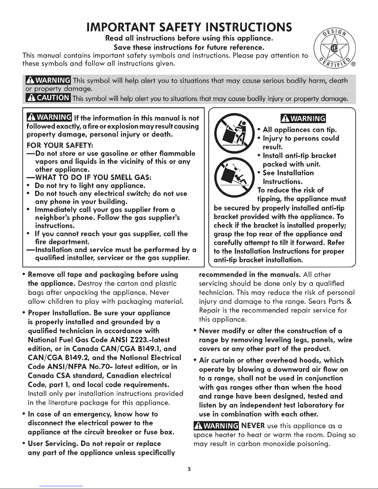
be secured by properly installed anti-tip
bracket provided with the appliance. To
check if the bracket is installed properly;
grasp the top rear of the appliance and
carefully attempt to tilt it forward. Refer
to the installation instructions for proper
anti-tip bracket installation.
* All appliances can tip.
* injury to persons could
result.
* install anti-tip bracket
packed with unit.
* See installation
instructions.
To reduce the risk of
tipping, the appliance must
* Remove all tape and packaging before using
the appliance. Destroy the carton and plastic
bags after unpacking the appliance. Never
allow children to play with packaging material.
* Proper Installation. Be sure your appliance
is properly installed and grounded by a
qualified technician in accordance with
National Fuel Gas Code ANSi Z223.-iatest
edition, or in Canada CAN/CGA B149.1, and
CAN/CGA B149.2, and the National Electrical
Code ANSI/NFPA No.70- latest edition, or in
Canada CSA standard, Canadian electrical
Code, part 1, and local code requirements.
Install only per installation instructions provided
in the literature package for this appliance.
* in case of an emergency, know how to
disconnect the electrical power to the
appliance at the circuit breaker or fuse box.
* User Servicing. Do not repair or replace
any part of the appliance unless specifically
recommended in the manuals. All other
servicing should be done only by a qualified
technician. This may reduce the risk of personal
injury and damage to the range. Sears Parts &
Repair is the recommended repair service for
this appliance.
Never modify or alter the construction of a
range by removing leveling legs, panels, wire
covers or any other part of the product.
Air curtain or other overhead hoods, which
operate by blowing a downward air flow on
to a range, shall not be used in conjunction
with gas ranges other than when the hood
and range have been designed, tested and
listen by an independent test laboratory for
use in combination with each other.
NEVER use this appliance as a
space heater to heat or warm the room. Doing so
may result in carbon monoxide poisoning.
iMPORTANT SAFETY iNSTRUCTiONS
NEVER cover any slots, holes or
passages in the oven bottom or cover an entire
rack with materials such as aluminum foil. Doing
so blocks air flow through the oven and may
cause carbon monoxide poisoning. Aluminum foil
linings may trap heat, causing a fire hazard.
* Do Not Use Water or Hour on Grease Fires.
Smother the fire with a pan ffd, or use baking
soda, a dry chemical or foam-type extinguisher.
* When heating fat or grease, watch it closely.
Fat or grease may catch fire if allowed to
become too hot.
Stepping, leaning, sitting or pulling
down on the door of this appliance can result
in serious injuries and may also cause damage
to the appliance. Do not allow children to climb
or play around the appliance. The weight of a
child on an open door may cause the range to tip,
resulting in serious burns or other injury.
Do not use the ovens for storage.
Do not store items of interest to
children in the cabinets above an appliance.
Children climbing on the appliance to reach
items could be seriously injured.
* Storage on Appliance. Flammable materials
should not be stored in an oven, near surface
burners. This includes paper, plastic and cloth
items, such as cookbooks, plasticware and
towels, as well as flammable liquids. Do not
store explosives, such as aerosol cans, on or
near the appliance.
* Do not leave children alone. Children should
not be left alone or unattended in the area
where an appliance is in use. They should
never be allowed to sit or stand on any part of
the appliance.
* DO NOT TOUCH SURFACE BURNERS, AREAS
NEAR THESE BURNERS OR INTERIOR
SURFACES OF THE OVEN. Both surface and
oven burners may be hot even though flames
are not visible. Areas near surface burners may
become hot enough to cause burns. During and
after use, do not touch, or let clothing or other
flammable materials touch these areas until
they have had sufficient time to cool. Among
these areas are the cooktop, surface facing the
cooktop, the oven vent openings and surfaces
near these openings, oven door and window.
* Wear Proper Apparel Loose-fitting or hanging
garments should never be worn while using
the appliance. Do not let clothing or other
flammable materials contact hot surfaces.
Use Only Dry Potholders. Moist or damp
potholders on hot surfaces may resuff in burns
from steam. Do not let the potholders touch hot
heating burners. Do not use a towel or other
bulky cloth instead of a potholder.
* Do Not Heat Unopened Food Containers.
Buildup of pressure may cause the container
to burst and resuff in injury.
* Remove the oven door from any unused
appffance if it is to be stored or discarded.
IMPORTANT--Do not attempt to operate the
appliance during a power failure. If power fails,
always turn off the appliance. If the appliance
is not turned off and the power resumes, it will
begin to operate again. Once the power resumes,
reset the clock and oven function.
iMPORTANT iNSTRUCTiONS FOR USING
YOUR COOKTOP
Use Proper Flame Size. Adjust flame
size so it does not extend beyond the edge of the
utensil. The use of undersized utensils will expose a
portion of the burner flame to direct contact and
may result in ignition of clothing. Proper relationship
of utensil to flame will also improve efficiency.
* Know which knob controls each surface
burner. Place a pan of food on the burner
before turning it on, and then turn the burner
off before removing the pan.
* Always turn knob to the full LITE position
when igniting top burners. Visually check that
burner has lit. Then adjust the flame so it does
not extend beyond the edge of the utensil.
* Utensil handles should be turned inward and not
extend over adjacent surface burners. To reduce
the risk of burns, ignition of flammable materials,
and spillage due to unintentional contact with
the utensil, the handle of the utensil should be
positioned so that it is turned inward, and does not
extend over adiacent surface burners
iMPORTANT SAFETY iNSTRUCTiONS
* Never leave surface burners unattended at
high heat seffings--Boilovers cause smoking
and greasy accumulations that may ignite, or
a pan that has boiled dry may melt.
" Protective liners--Do not use aluminum foil
to line surface burner pans, or oven bottom,
except as suggested in this manual, improper
installation of these liners may result in risk of
electric shock, or fire.
Glazed cooking utensils--Only certain types
of glass, glass/ceramic, ceramic, earthenware,
or other glazed utensils are suitable for cooktop
service without breaking due to the sudden
change in temperature. Check the manufacturer's
recommendations for cooktop use.
iMPORTANT iNSTRUCTiONS FOR USING
YOUR OVEN
* Use Care When Opening an Oven Door--Stand
to the side of the appliance when opening the
door of a hot oven. Let hot air or steam escape
before you remove or replace food in the oven.
" Keep Oven Vent Ducts Unobstructed. The oven
is vented at the center trim above the oven and
below the console. Touching the surfaces in this
area when the oven is operating may cause
severe burns. Also, do not place plastic or heat-
sensitive items near the oven vent. These items
could melt or ignite.
*Placement of Oven Racks. Always place
oven racks in desired location while oven is
cool. Remove all utensils from the rack before
removing rack. If rack must be moved while
oven is hot, use extreme caution. Use pot
holders and grasp the rack with both hands to
reposition. Do not let pot holders contact the
hot oven burner or interior of the oven.
• Do not touch a hot oven light bulb with a
damp cloth. Doing so could cause the bulb to
break. Disconnect the appliance or shut off: the
power to the appliance before removing and
replacing the bulb.
iMPORTANT iNSTRUCTiONS FOR CLEANING
YOUR RANGE
* Clean the appliance regularly to keep all
parts free of grease that could catch fire.
Exhaust fan ventilation hoods and grease filters
should be kept clean. Do not allow grease to
accumulate. Greasy deposits in the fan could
catch fire. Refer to the hood manufacturer's
instructions for cleaning.
* Kitchen cleaners and aerosols--Always follow
the manufacturer's recommended directions for
use. Be aware that excess residue from cleaners
and aerosols may ignite causing damage and
injury.
Clean in the serf-cleaning cycle only the parts
of the appffance listed in this Use & Care
Guide. Before using the self-cleaning cycle of
the appliance, remove the broiler pan and any
utensils stored in the appliance.
Do not clean the oven door gasket. The door
gasket isessential for a good seal. Care should be
taken not to rub, damage or move the gasket.
" Do not use oven cleaners. No commercial oven
cleaner or oven liner protective coating of any
kind should be used in or around any part of the
appliance
The health of some birds is extremely
sensitive to the fumes given off: during the self-
clean cycle of any oven. Move birds to another
well ventilated room.
• Do not use the broiler pan without its insert.
The broiler pan and grid allow dripping fat to
drain and be kept away from the high heat of
the broiler.
* Do not cover the broiler grid or oven bottom
with aluminum foil. Exposed fat and grease
could ignite.
SAVE THESE INSTRUCTIONS FOR FUTURE REFERENCE.
iMPORTANT SAFETY NOTICE
The California Safe Drinking Water and Toxic
Enforcement Act requires the Governor of California
to publish a list of substances known to the state
to cause cancer, birth defects or other productive
harm, and requires businesses to warn customers
of potential exposure to such substances.
5
Product Record
In this space below, record the date of purchase, model and
serial number of your product. You will find the model and
serial number printed on the serial plate.
Model No. 790.
Serial No.
Date of purchase
Save these instructions and your sales receipt for future
reference.
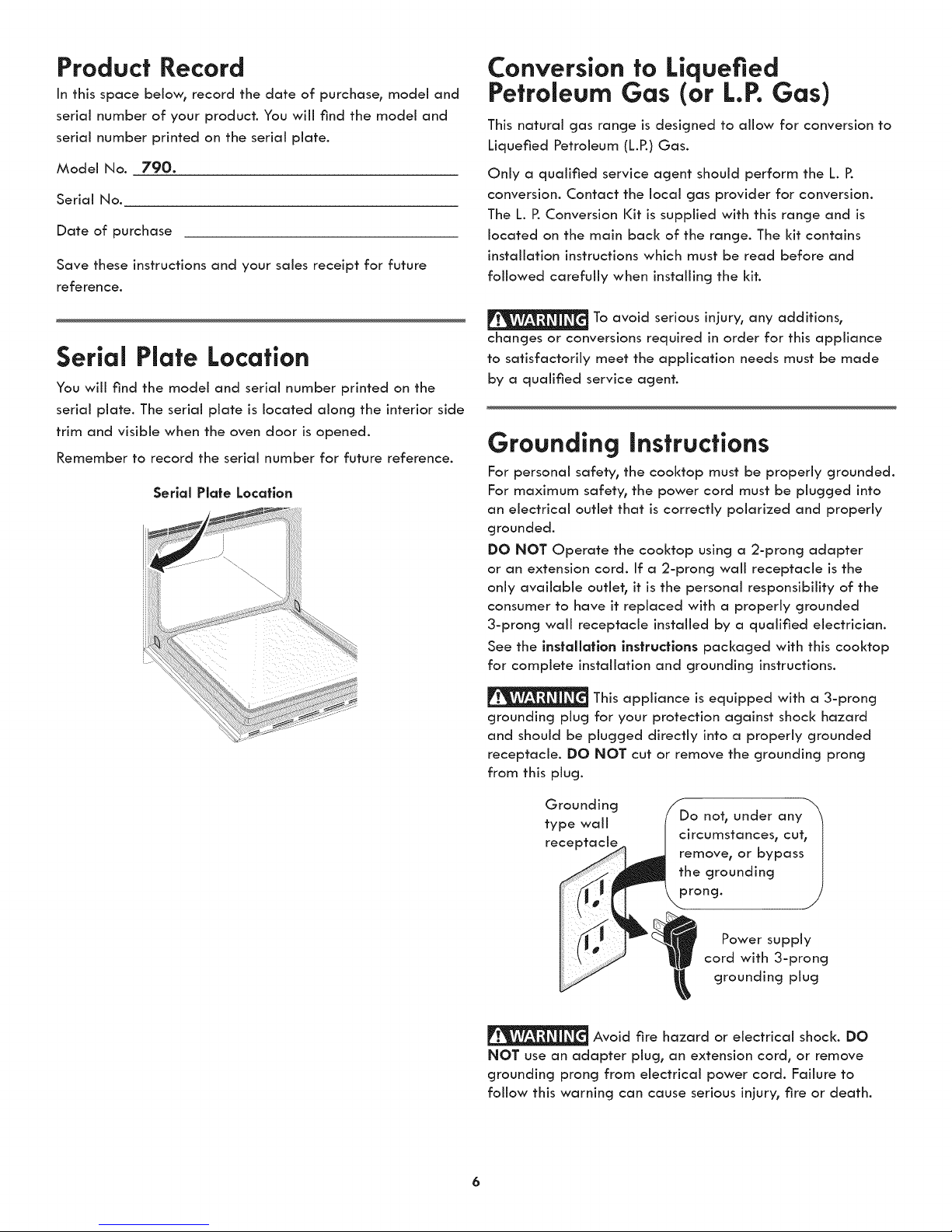
Serial Plate Location
You will find the model and serial number printed on the
serial plate. The serial plate is located along the interior side
trim and visible when the oven door is opened.
Remember to record the serial number for future reference.
Serlal Plate Location
Conversion to Liquefied
Petroleum Gas (or L.P.Gas)
This natural gas range is designed to allow for conversion to
Liquefied Petroleum (L.P.) Gas.
Only a qualified service agent should perform the L. P.
conversion. Contact the local gas provider for conversion.
The L. P.Conversion Kit is supplied with this range and is
located on the main back of the range. The kit contains
installation instructions which must be read before and
followed carefully when installing the kit.
To avoid serious injury, any additions,
changes or conversions required in order for this appliance
to satisfactorily meet the application needs must be made
by a qualified service agent.
Grounding instructions
For personal safety, the cooktop must be properly grounded.
For maximum safety, the power cord must be plugged into
an electrical outlet that is correctly polarized and properly
grounded.
DO NOT Operate the cooktop using a 2-prong adapter
or an extension cord. If a 2-prong wall receptacle is the
only available outleh it is the personal responsibility of the
consumer to have it replaced with a properly grounded
3-prong wall receptacle installed by a qualified electrician.
See the installatlon instructions packaged with this cooktop
for complete installation and grounding instructions.
This appliance is equipped with a 3-prong
grounding plug for your protection against shock hazard
and should be plugged directly into a properly grounded
receptacle. DO NOT cut or remove the grounding prong
from this plug.
Grounding
type wall
rece
Avoid fire hazard or electrica! shock. DO
NOT use an adapter plug, an extension cord, or remove
grounding prong from electrical power cord. Failure to
follow this warning can cause serious injury, fire or death.
Do not, under any
circumstances, cut,
remove, or bypass
the grounding
prong.
cord with 3-prong
Power supply
grounding plug
Features at a Glance
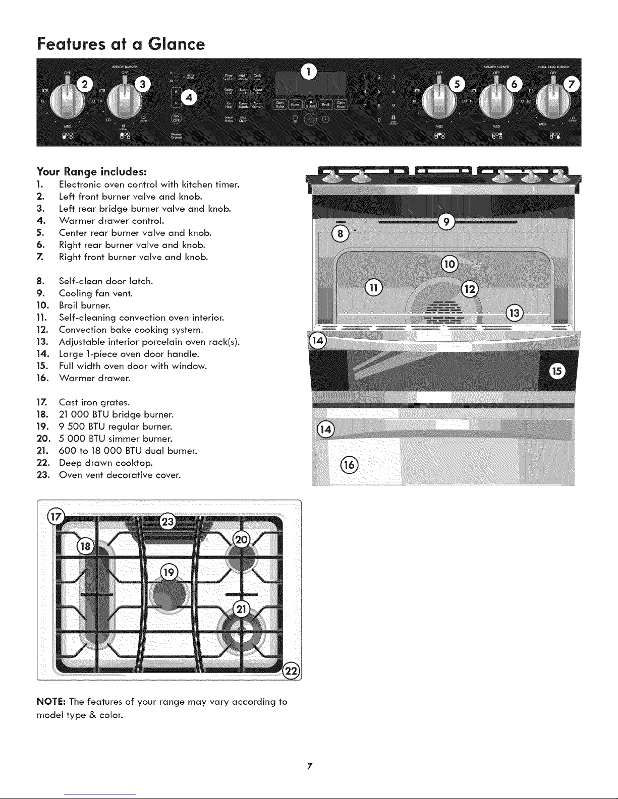
Your Range includes:
|. Electronic oven control with kitchen timer.
2. Left front burner valve and knob.
3. Left rear bridge burner valve and knob.
4. Warmer drawer control.
5. Center rear burner valve and knob.
6. Right rear burner valve and knob.
7. Right front burner valve and knob.
8. Self-clean door latch.
9. Cooling fan vent.
10. Broil burner.
11. Self-cleaning convection oven interion
12. Convection bake cooking system.
13. Adjustable interior porcelain oven rack(s).
14. Large 1-piece oven door handle.
15. Full width oven door with window.
16. Warmer drawer.
17. Cast iron grates.
18. 21 000 BTU bridge burner.
19. 9 500 BTU regular burner.
20. 5 000 BTU simmer burner.
21. 600 to 18 000 BTU dual burner.
22. Deep drawn cooktop.
23. Oven vent decorative cover.
NOTE: The features of your range may vary according to
model type & color.
7
Before Setting Oven Controls
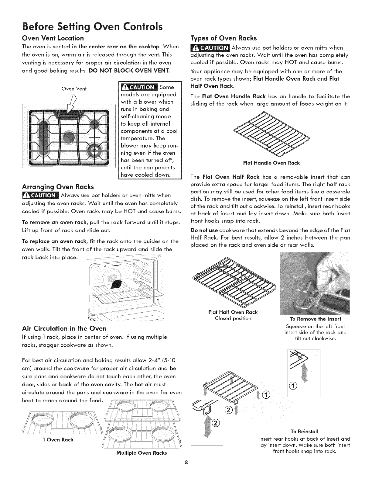
Oven Vent Location
The oven is vented in the center rear an the coaktap. When
the oven is on, warm air is released through the vent. This
venting is necessary for proper air circulation in the oven
and good baking results. DO NOT BLOCK OVEN VENT.
Oven Vent
Arranging Oven Racks
Always use pot holders or oven mitts when
adjusting the oven racks. Wait until the oven has completely
cooled if possible. Oven racks may be HOT and cause burns.
To remove an oven rack, pull the rack forward until it stops.
Lift up front of rack and slide out.
To replace an oven rack, fit the rack onto the guides on the
oven walls. Tilt the front of the rack upward and slide the
rack back into place ................ i....................
_]__ Some
models are equipped
with a blower which
runs in baking and
self-cleaning mode
to keep all internal
components at a cool
temperature. The
blower may keep run-
ning even if the oven
has been turned off,
until the components
have cooled down.
Types of Oven Racks
Always use pot holders or oven mitts when
adjusting the oven racks. Wait until the oven has completely
cooled if possible. Oven racks may HOT and cause burns.
Your appliance may be equipped with one or more of the
oven rack types shown; Flat Handle Oven Rack and Flat
Half Oven Rack.
The Flat Oven Handle Rack has an handle to facilitate the
sliding of the rack when large amount of foods weight on it.
Fiat Handle Oven Rack
The Flat Oven Half Rack has a removable insert that can
provide extra space for larger food items. The right half rack
portion may still be used for other food items like a casserole
dish. To remove the insert, squeeze on the left front insert side
of the rack and tilt out clockwise. To reinstall, insert rear hooks
at back of insert and lay insert down. Make sure both insert
front hooks snap into rack.
Do not use cool<ware that extends beyond the edge of the Flat
Half Rack. For best results, allow 2 inches between the pan
placed on the rack and oven side or rear walls.
Air Circulation in the Oven
If using 1 rack, place in center of oven. If using multiple
racks, stagger cookware as shown.
For best air circulation and baking results allow 2-4" (5-10
cm) around the cookware for proper air circulation and be
sure pans and cool<ware do not touch each other, the oven
door, sides or back of the oven cavity. The hot air must
circulate around the pans and cookware in the oven for even
Multiple Oven Racks
Fiat Half Oven Rack
Closed position To Remove the insert
Squeeze on the left front
insert side of the rack and
tilt out clockwise.
To Reinstall
Insert rear hooks at back of insert and
lay insert down. Make sure both insert
front hooks snap into rack.

Surface Cookware Recommendations
Use Proper Cookware
Cookware should hove flat bottoms that make good contact
with the cooktop grate. Check for flatness by rotating a
ruler across the bottom of the cookware (See Figure 1). Be
sure to follow the recommendations for using cookware as
shown in Figure 2.
Note: The size and type of cookware used wiil influence the
setting needed for best cooking results.
Note: Always use a utensil for its intended purpose. Follow
manufacturer's instructions. Some utensils were not made to
be used in the oven or on the cooktop.
Figure |
CORRECT
* Flat bottom and straight
sides.
° Tight fitting lids.
* Weight of handle does
not tilt pan. Pan is well
balanced.
° Pan sizes match the
amount of food to be
prepared.
° Made of material that
conducts heat well.
° Easy to dean.
INCORRECT
* Curved and warped pan bot-
toms.
f
" Pan overhangs unit by more
than 2.5 cm (1").
• Heavy handle tilts pan.
• Flame extends beyond unit.
Cookware Material types
The cookware material determines how evenly and quickly
heat is transferred from the surface unit to the pan bottom.
The most popular materials available are:
ALUMINUM - Excellent heat conductor. Some types of food
wiil cause it to darken (Anodized aluminum cookware resists
staining & pitting).
COPPER - Excellent heat conductor but discolors easily.
STAINLESS STEEL - Slow heat conductor with uneven
cooking results. Is durable, easy to clean and resists staining.
CAST IRON - A poor heat conductor however will retain
heat very well. Cooks evenly once cooking temperature is
reached.
PORCELAIN-ENAMEL on METAL - Heating characteristics
wili vary depending on base material.
GLASS - Slow heat conductor.
Using a Wok (not supplied)
Woks with flat bottoms suitable for use on your cooktop
are available in most cookshop or hardware stores. Round-
bottomed woks (with a support ring that does not extend
beyond the burner unit) may also be used. The metal ring
was designed to support the wok safely when it is filled with
large amounts of liquids (soup making) or fat (frying).
Wire trivets: Do not use wire trivets. Cookware bottoms must
be in direct contact with the grates.
Figure 2
Specialty pans such as lobster pots, griddles and pressure
cookers may be used but must conform to the above
recommended cookware requirements.
DO NOT use a wok if it is equipped wlfh
a metal ring that extends beyond the
burner unit. Because fhls ring traps heat,
the surface unlf and cookfop surface
could be damaged.
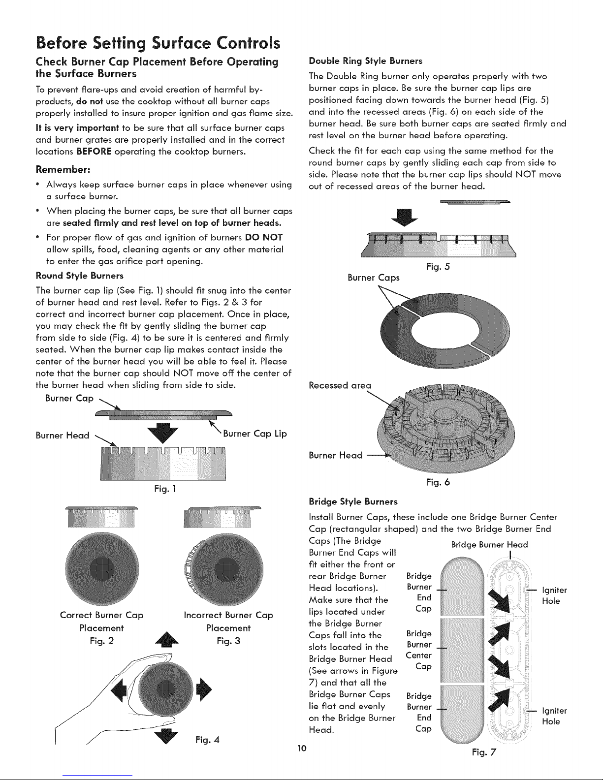
Before Setting Surface Controls
Check Burner Cap Placement Before Operating
the Surface Burners
To prevent flare-ups and avoid creation of harmful by-
products, do not use the cooktop without aii burner caps
property installed to insure proper ignition and gas flame size.
It is very important to be sure that aii surface burner caps
and burner grates are property installed and in the correct
locations BEFORE operating the cooktop burners.
Remember:
° Always keep surface burner caps in place whenever using
a surface burner.
° When placing the burner caps, be sure that all burner caps
are seated firmly and rest level on top of burner heads.
° For proper flow of gas and ignition of burners DO NOT
aflow spills, food, cleaning agents or any other material
to enter the gas orifice port opening.
Round Style Burners
The burner cap lip (See Fig. 1) should fit snug into the center
of burner head and rest level. Refer to Figs. 2 & 3 for
correct and incorrect burner cap placement. Once in place,
you may check the fit by gently sliding the burner cap
from side to side (Fig. 4) to be sure it is centered and firmly
seated. When the burner cap lip makes contact inside the
center of the burner head you will be able to feel it. Please
note that the burner cap should NOT move off the center of
the burner head when sliding from side to side.
Double Ring Style Burners
The Double Ring burner only operates property with two
burner caps in place. Be sure the burner cap lips are
positioned facing down towards the burner head (Fig. 5)
and into the recessed areas (Fig. 6) on each side of the
burner head. Be sure both burner caps are seated firmly and
rest level on the burner head before operating.
Check the fit for each cap using the same method for the
round burner caps by gently sliding each cap from side to
side. Please note that the burner cap lips should NOT move
out of recessed areas of the burner head.
Fig. 5
Burner Caps
Recessed area
Burner Cap
Burner Head _ _ '_ Burner Cap Lip
Fig. 1
Correct Burner Cap Incorrect Burner Cap
Placement Placement
Fig. 2 _ Fig. 3
Fig. 4
Burner Head
Fig. 6
Bridge Style Burners
Install Burner Caps, these include one Bridge Burner Center
Cap (rectangular shaped) and the two Bridge Burner End
Caps (The Bridge
Burner End Caps will
fit either the front or
rear Bridge Burner Bridge
Head locations). Burner
Make sure that the End
lips located under Cap
the Bridge Burner
Caps fall into the Bridge
slots located in the Burner
Bridge Burner Head Center
(See arrows in Figure Cap
7) and that aii the
Bridge Burner Caps
lie flat and evenly
on the Bridge Burner
Head.
10
Burner
End
Bridge
Cap
Bridge Burner Head
I
Fig. 7
igniter
Hole
igniter
Hole
Setting Surface Controls
Setting Proper Surface Burner Flame Size
For most cooking, start on the highest control setting and
then turn to a lower one to complete the process. Use the
recommendations below as a guide for determining proper
flame size for various types of cooking. The size and type
of utensil used and the amount of food being cooked will
influence the setfinc needed for cooking.
High Flame Start most foods; bring water to a boil;
pan broiling.
Medium Flame Maintain a slow boil; thicken sauces,
ii
Low Flame Keep foods cooking; poach; stewing.
_These settings are based on using medlum-welght metal
or aluminum pans wlfh llds. Settings may vary when using
other types of pans. The color of the flame is the key to
proper burner adjustment. A good flame is dear, blue and
hardly visible in a well-lighted room. Each cone of flame
should be steady and sharp. Clean burner if flame is yellow-
orange.
Regardless of size, always select cookware that is suitable
for the amount and type of food being prepared. Select a
burner and flame size appropriate to the pan. Never allow
flames to extend beyond the outer edge of the pan.
Never extend the flame beyond the outer edge of the
utensil. A higher flame wastes heat and energy and
increases your risk of being burned by the flame (Figure 1).
For deep fat frying, use a thermometer and adjust the
surface control knob accordingly. If the fat is too cool, the
food will absorb the fat and be greasy. If the fat is too
hot, the food will brown so quickly that the center will be
undercooked. Do not attempt to deep fat fry too much food
at once as the food will neither brown nor cool< properly.
gravies; steaming.
Proper Improper
flame flame
size size
Figure 1
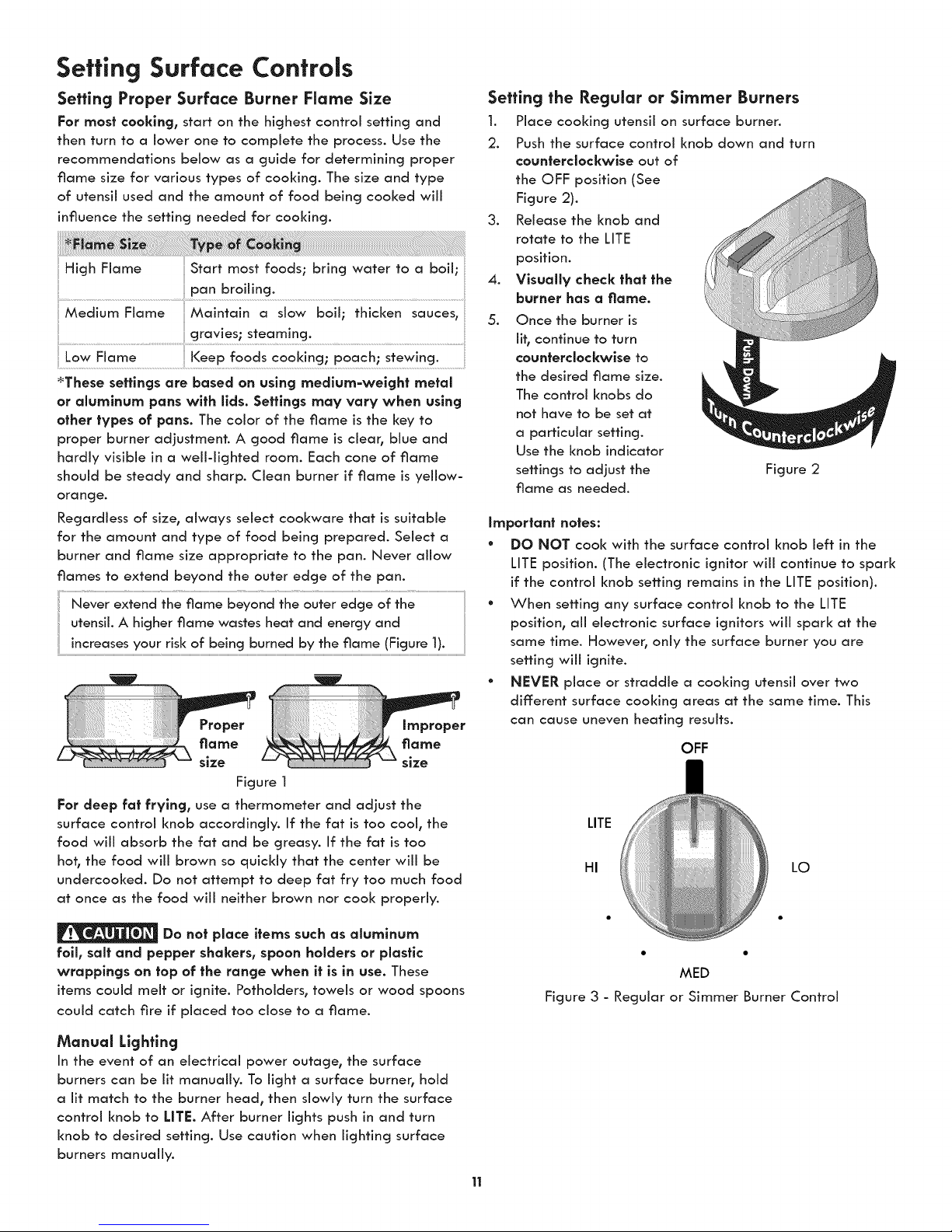
Setting the Regular or Simmer Burners
1. Place cooking utensil on surface burner.
2. Push the surface control knob down and turn
counterclockwise out of
the OFF position (See
Figure 2).
3. Release the knob and
rotate to the LITE
position.
4. Visually check thai the
burner has a flame.
5. Once the burner is
lit, continue to turn
counterclockwise to
the desired flame size.
The control knobs do
not have to be set at
a particular setting.
Use the knob indicator
settings to adjust the Figure 2
flame as needed.
important notes:
° DO NOT cool< with the surface control knob left in the
LITE position. (The electronic ignitor will continue to spark
if the control knob setting remains in the LITE position).
° When setting any surface control knob to the LITE
position, all electronic surface ignitors will spark at the
same time. However, only the surface burner you are
setting will ignite.
• NEVER place or straddle a cooking utensil over two
different surface cooking areas at the same time. This
can cause uneven heating results.
OFF
LO
HI •
Do not place items such as aluminum
foil, salt and pepper shakers, spoon holders or plastic
wrappings on fop of the range when it is in use. These
items could melt or ignite. Pothoiders, towels or wood spoons
could catch fire if placed too dose to a flame.
Manual Lighting
In the event of an electrical power outage, the surface
burners can be lit manually. To light a surface burner, hold
a lit match to the burner head, then slowly turn the surface
control knob to LITE After burner lights push in and turn
knob to desired setting. Use caution when lighting surface
burners manually.
MED
Figure 3 - Regular or Simmer Burner Control

Setting Surface Controls
Setting the Bridge Burner
The Bridge Burner should be used with rectangular shaped
cookware. Cookware like a cast-iron Griddle is designed
specifically for best results with the Bridge Burner.
The Bridge Burner feature may be used to combine the
cooking power of 2 or if needed 3 gas surface Burners
located along the left-hand side of the cooldop. The left
rear and left center Burners are controlled by the left rear
surface Control Knob. In addition the left front Burner may
be added to the Bridge Burner with the left front gas Control
Knob.
Operating the Bridge Burner
1. Push the left rear surface
control knob in and turn
counterclockwise out of
the OFF position (See
Figure 1).
.
Release the knob and
rotate to the LITE
position.
.
Visually check that the
left rear Burner has llt.
4.
Continue to rotate
the gas control knob
counterclockwise to the
"HI bridge" position Figure 1
(Figure 2).
.
Visually check that both the left rear and left center
Burners are lit.
6.
When both burners are lit, continue to turn the control
knob counterclockwlse to adjust to the desired flame
size for both burners together.
Note: The markings between the "HI bridge" and the "LO
bridge" settings adjust the flame size for both burners.
Add the left front Burner if needed. Once lit, visually
adjust the flame size of the left front burner to match __
the flame size of the bridge burner. ____l_nlm __
Important notes:
* DO NOT cool< with any of the surface control knobs in
the LITE position (The electronic ignitor will continue to
spark if the knob is left in the LITE position).
° When setting any surface control knob to the LITE
position, all electronic surface ignitors will spark at the
same time. However, only the surface burner you are
setting will ignite.
° If only the left rear surface Burner is needed, adjust the
settings between the 1st HI and LO.
° The left front Burner may be added to the Bridge Burner
by setting the left front gas Control I<nob.
BRIDGE BURNER
OFF
Figure 2 - Bridge Burner
12
 Loading...