

Page 1

Installation Manual
Manual de Instalación
English /
Model/Modelo: 721.9604*
Español
Kenmore Elite®
ENGLISH
ESPAÑOL
Electric Range
Estufa Eléctrica
* = color number, número de color
P/N MFL69645901 Rev 00
Sears Brands Management Corporation
Hoffman Estates, IL 60179 U.S.A.
www.kenmore.com
www.sears.com
Page 2

TABLE OF CONTENTS
2
TABLE OF CONTENTS
3 IMPORTANT SAFETY INSTRUCTIONS
5 PREPARING FOR INSTALLATION
5 Before you Begin
6 Dimensions and Clearances
7 ELECTRICAL CONNECTIONS
7 Electrical Connection Requirements
7 Connect Range Cord
8 3-Wire Connection with a Power Supply Cord
9 4-Wire Connection with a Power Supply Cord
9 3-Wire Connection: Conduit
10 4-Wire Connection: Conduit
11 INSTALLING THE RANGE
11 Anti-Tip Device Installation
11 Final Installation
12 Test Run
Page 3
IMPORTANT SAFETY INSTRUCTIONS
3
IMPORTANT SAFETY INSTRUCTIONS
Read and follow all instructions before using your oven to prevent the risk of fire, electric shock, personal injury, or damage
when using the range. This guide does not cover all possible conditions that may occur. For further assistance contact your
service agent or manufacturer.
This is the safety alert symbol. This symbol alerts you to potential hazards that can cause personal injury to
you and others. All safety messages will follow the safety alert symbol and either the word “WARNING” or
“CAUTION”.
WARNING
This symbol will alert you to hazards or unsafe practices which could cause serious bodily harm or death.
CAUTION
This symbol will alert you to hazards or unsafe practices which could cause bodily injury or property damage.
WARNING
• The information in this manual should be followed exactly to avoid fire, electrical shock, property damage, personal
injury, or death.
• Do not step or sit on the oven door. Install the Anti-Tip Bracket supplied with the range.
− The range could be tipped and injury might result from spilled hot liquid, food, or the range itself.
− If the range is pulled away from the wall for cleaning, service, or any other reason, ensure that the Anti-Tip Device
is properly reengaged when the range is pushed back against the wall.
• All ranges can tip and injury could result.
− To prevent accidental tipping of the range, attach an approved anti-tip device to the wall. (See "Installing the Anti-
Tip Device" in this manual and the instructions packaged with the device.)
− To check if the device is installed and engaged properly, carefully tip the range forward. The anti-tip device should
engage and prevent the range from tipping over.
− If you pull the range out from the wall for any reason, make sure the anti-tip device is engaged when you push the
range back against the wall.
• Use two or more people to move and install range. (Excessive Weight Hazard)
− Failure to do so can result in back injury or other injury.
• Do not use the oven door handles to pull, push, or move the range.
− Doing so can result in serious damage to the door of the range.
• New branch-circuit installations (1996 NEC) for mobile homes, recreational vehicles, and installations where local
codes do not allow grounding through the neutral wire require a 4-conductor UL listed range cord or 4-wire conduit
connection.
• Do not modify the power supply cord or plug. If the plug will not fit in the outlet, have a proper outlet installed by
a qualified electrician.
ENGLISH
Page 4
IMPORTANT SAFETY INSTRUCTIONS
4
WARNING
• Do not use an extension cord with this appliance.
• This appliance must be electrically grounded.
• Do not allow the power cord to be pinched or crushed by the range or other heavy objects.
− Doing so can result in serious burns or electrical shock.
• Never remove the protective cover on the rear of the lower oven..
− Doing so can cause serious damage to power cord, resulting in serious burns and electric shock.
• The middle (neutral or ground) wire of a 3-wire power cord or a 3-wire conduit must be connected to the middle post
of the main terminal block. The remaining two wires of the power cord or conduit must be connected to the outside
posts of the main terminal connection block.
− Failure to do so can result in electrical shock, severe personal injury or death.
• Only a 4-conductor power-supply cord kit rated for 120/240 volts, 50 amperes and marked for use with ranges
with closed-loop connectors or open-end spade lugs with upturned ends shall be used. The middle (neutral) wire of
the power cord or 4-wire conduit must be connected to the middle post of the main terminal block. The other two
wires of the power cord or conduit must be connected to the outside posts of the main terminal connection block. The
fourth ground wire must be connected to the frame of the range with the ground screw.
− Failure to do so can result in electrical shock, severe personal injury or death.
CAUTION
• Wear gloves during the installation procedure.
− Failure to do so can result in bodily injury.
• The wall covering, countertop and cabinets around the range must be able to withstand the heat (up to 194°F)
generated by the range.
− Discoloration, delamination or melting may occur.
− This range has been designed to comply with the maximum allowable wood cabinet temperatures of 194°F.
• Avoid placing cabinets above the range.
• If there are cabinets above the range, install a range hood that projects horizontally a minimum of 5 inches beyond
the bottom of the cabinets.
− Doing so will reduce the risk of burns or fire caused by reaching into cabinets above the heated surface elements.
• Do not install the range in a humid area. Splashing the range with water or any electrolyte can result in electric
shock.
• Do not let cooking grease or flammable material accumulate in or near the range.
− Doing so so can result in serious burns.
Page 5
PREPARING FOR INSTALLATION
PREPARING FOR INSTALLATION
5
ENGLISH
BEFORE YOU BEGIN
Remove all tape and packing materials before using the range.
Dispose of all plastic bags after unpacking the range.
Never allow children to play with packing materials.
You can download the installation and owner’s manual at:
http://www.kenmore.com
WARNING
• The information in this manual should be followed
exactly to avoid a fire or electric shock which may
result in property damage, personal injury, or death.
WARNING
Tip - Over Hazard
A child or adult can tip the range and be
killed. Verify the anti-tip bracket has been
installed. Ensure the anti-tip bracket is
engaged when the range is moved.
Do not operate the range without the antitip bracket in place. Failure to follow these
instructions can result in death or serious
burns to children and adults.
To check visually that leveling leg is inserted into
bracket, grasp the top rear edge of the range
and carefully attempt to tilt it forward.
bracket
CAUTION
• Wear gloves during the installation procedure.
− Failure to do so can result in bodily injury.
Keep these instructions with your Use & Care Guide for
future reference.
• As when using any appliance generating heat, there
are certain safety precautions you should follow.
• Be sure your range is installed and grounded properly
by a qualified installer or service technician.
• Make sure the wall coverings around the range can
withstand the heat generated by the range.
• To eliminate the need to reach over the surface
elements, cabinet storage space above the elements
should be avoided.
Leveling
leg
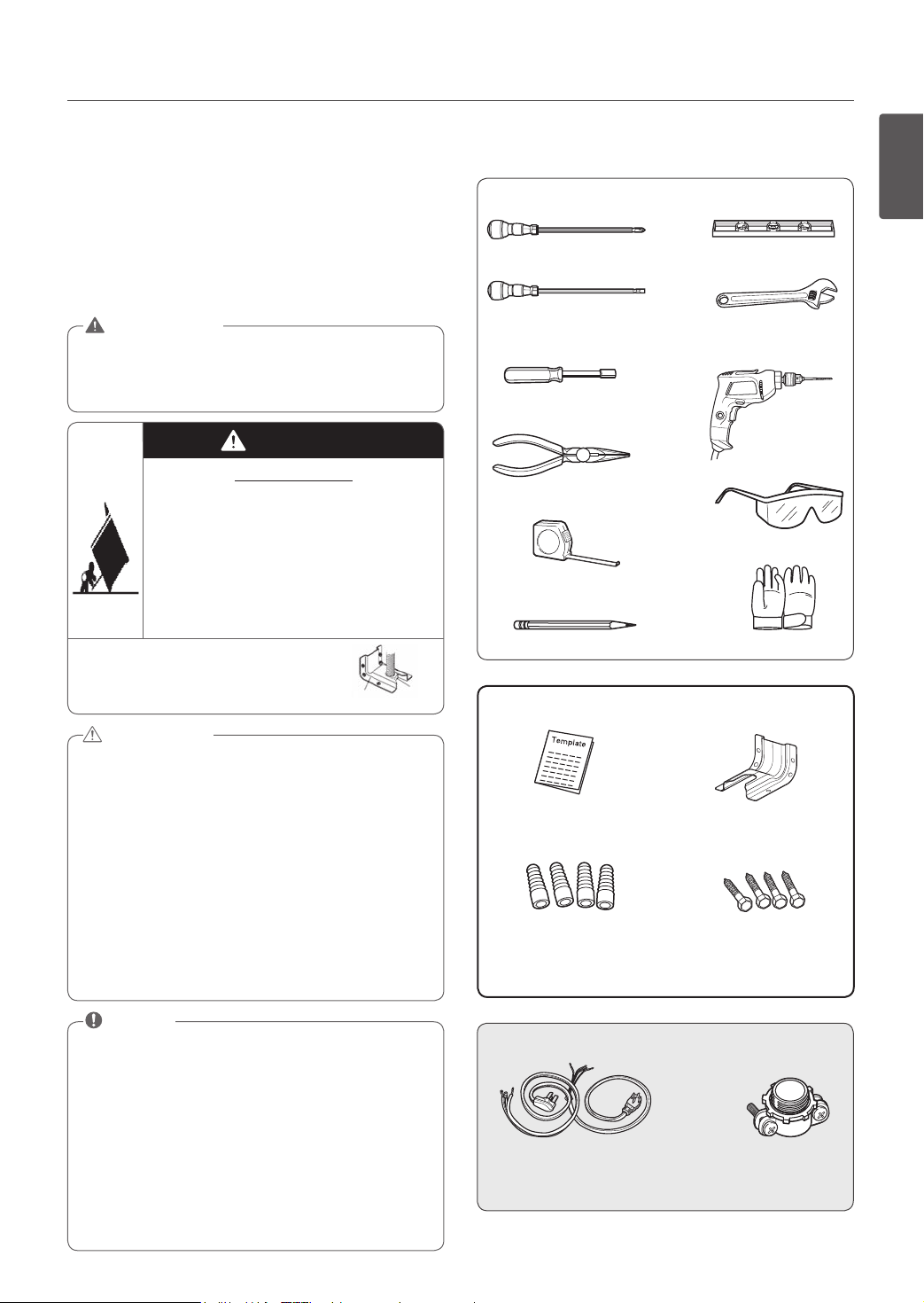
TOOLS NEEDED
Phillips Screwdriver
Flat-blade
Screwdriver
1
/4” Nut Driver
Pliers
Tape Measure
Pencil
PARTS PROVIDED
Template (1)
Anchor Sleeves (4)
(For Anti-Tip Bracket Mounted on
Concrete Floors and Walls)
Level
Adjustable Wrench
Drill
Safety Glasses
Gloves
Anti-Tip Bracket Kit (1)
Lag Bolts (4)
NOTE
• Read all instructions contained in these installation
instructions before installing range.
• Remove all tape and packing materials from the
oven compartments before connecting the electrical
supply to the range.
• Observe all governing codes and ordinances.
• Be sure to leave these instructions with the consumer.
• Dispose of all plastic bags after unpacking the range.
Never allow children to play with packing materials.
• You can download the Installation Guide and Use &
Care Guide at: www.kenmore.com
PARTS NOT PROVIDED
(UL Approved 40 or 50 AMP)
4-Wire Cord OR 3-Wire Cord
Strain Relief
(For Conduit
Installations Only)
Page 6
PREPARING FOR INSTALLATION
6
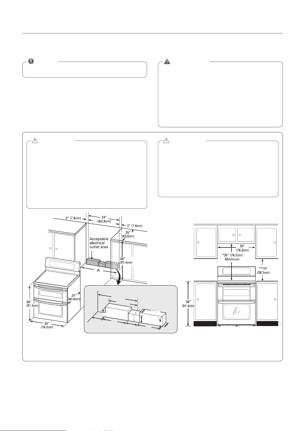
DIMENSIONS AND CLEARANCES
NOTE
Save for the use of the local electrical inspector.
For installation in CANADA, a Free-standing range is
not to be installed closer than
15
/32" (12mm) from any
adjacent surface.
CAUTION
• The wall covering, countertop and cabinets
around the range must be able to withstand the
heat (up to 194°F) generated by the range.
− Discoloration, delamination or melting may
occur.
− This range has been designed to comply
with the maximum allowable wood cabinet
temperatures of 194°F.
WARNING
• Use two or more people to move and install range.
(Excessive Weight Hazard)
– Failure to do so can result in back injury or other
injury.
• Do not use the oven handles to push, pull, or move
the range.
− Doing so can result in serious damage to the door
of the range.
CAUTION
• Avoid installing cabinets directly over the range.
• If cabinets are installed over the range, install a
range hood that projects horizontally a minimum
of 5 inches beyond the bottom of the cabinets.
− Doing so will reduce the risk of burns or fire
caused by reaching above the heated surface
elements.
Normal
countertop
depth
Countertop
height
Cabinet
opening
Wall
Cabinet
(10cm)
4”
15”(38cm)
6”
6”
(15.2cm)
(15.2cm)
(23cm)
9”
11”(28cm)
4”
(10cm)
Center
2.5”(6.3cm)2.5”(6.3cm)
5”
(13cm)
(15.2cm)
9”
(23cm)
6”
2.5”
(6.3cm)
A = 30" (76.2 cm) For U.S.A
= 30" to 31" (76.2 to 78.7 cm) For CANADA
FIGURE 1
FIGURE 2
MINIMUM DIMENSIONS (Figure 2)
* 30" (76.2 cm) minimum clearance between the top of the cooking surface and the bottom of an unprotected wood or
metal cabinet; or 24" (60.9 cm) minimum when bottom of wood or metal cabinet is protected by not less than
1
/4" (6.4
cm) flame retardant millboard covered with not less than no. 28 MSG sheet steel, 0.015" (0.381 mm) stainless steel, 0.024"
(0.610 mm) aluminum or 0.020" (0.508 mm) copper.
** 15" (38.1 cm) minimum between countertop and adjacent cabinet bottom.
Page 7
ELECTRICAL CONNECTIONS
ELECTRICAL CONNECTION
REQUIREMENTS
This appliance must be installed and grounded on a branch
circuit by a qualified technician in accordance with the
National Electrical code ANSI/NFPA NO. 70 - latest edition.
All wiring should conform to Local and NEC codes. This
range requires a single-phase, 3 wire, AC 120/208V or
120/240V 60Hz electrical system. Use only a 3-conductor
or a 4-conductor UL-listed range cord with closed-loop
terminals, open-end spade lugs with upturned ends, or similar
termination. DO NOT install the power cord without a strain
relief.
A range cord rated at 40 amps with 120/240 minimum volt
range is required. If a 50 amp range cord is used, it should be
marked for use with 1
This appliance may be connected by means of conduit or
power cord. If conduit is being used, go to page 9 for 3
wire conduit connections or page 10 for 4 wire conduit
connections.
WARNING
• New branch-circuit installations (1996 NEC) for
mobile homes, recreational vehicles, and installations
where local codes do not allow grounding through
the neutral wire require a 4-conductor UL listed
range cord or 4 wire conduit connection.
• Power supply cord and plug should not be modified.
If the plug will not fit in the outlet, have a proper
outlet Installed by a qualified electrician.
• Do not use an extension cord to connect to power.
Connect the power cord and plug directly.
• Electrical ground is required on this appliance.
• Make sure that the power cord is not pinched by the
range or heavy objects.
− Failure to do so can result in serious burns or
electrical shock.
Specified power-supply-cord kit rating
Range rating, watts Specified rating
120/240 volts
3-wire
8,750 -
16,500
16,501 22,500
3, 4 - Wire electrical wall Receptacle
3
/8” diameter connection openings.
Diameter (inches) of Range
connection Opening
Power cord Conduit
3
1
/4”
120/208 volts
3-wire
7,801 12,500
12,501 -
18,500
of powersupply- cord
kit, amperes
40 or 50A501 3/8”
4 Wire receptacle (14-50R)
3 Wire receptacle (10-50R)
FIGURE 3
1
/8”
1
3
1
/8”
ELECTRICAL CONNECTIONS
7
CONNECT RANGE CORD
WARNING
• Do not operate the range without the protective
covering on the rear of the lower oven in place.
− Doing so can cause serious damage to the power cord,
resulting in severe burns and electric shock.
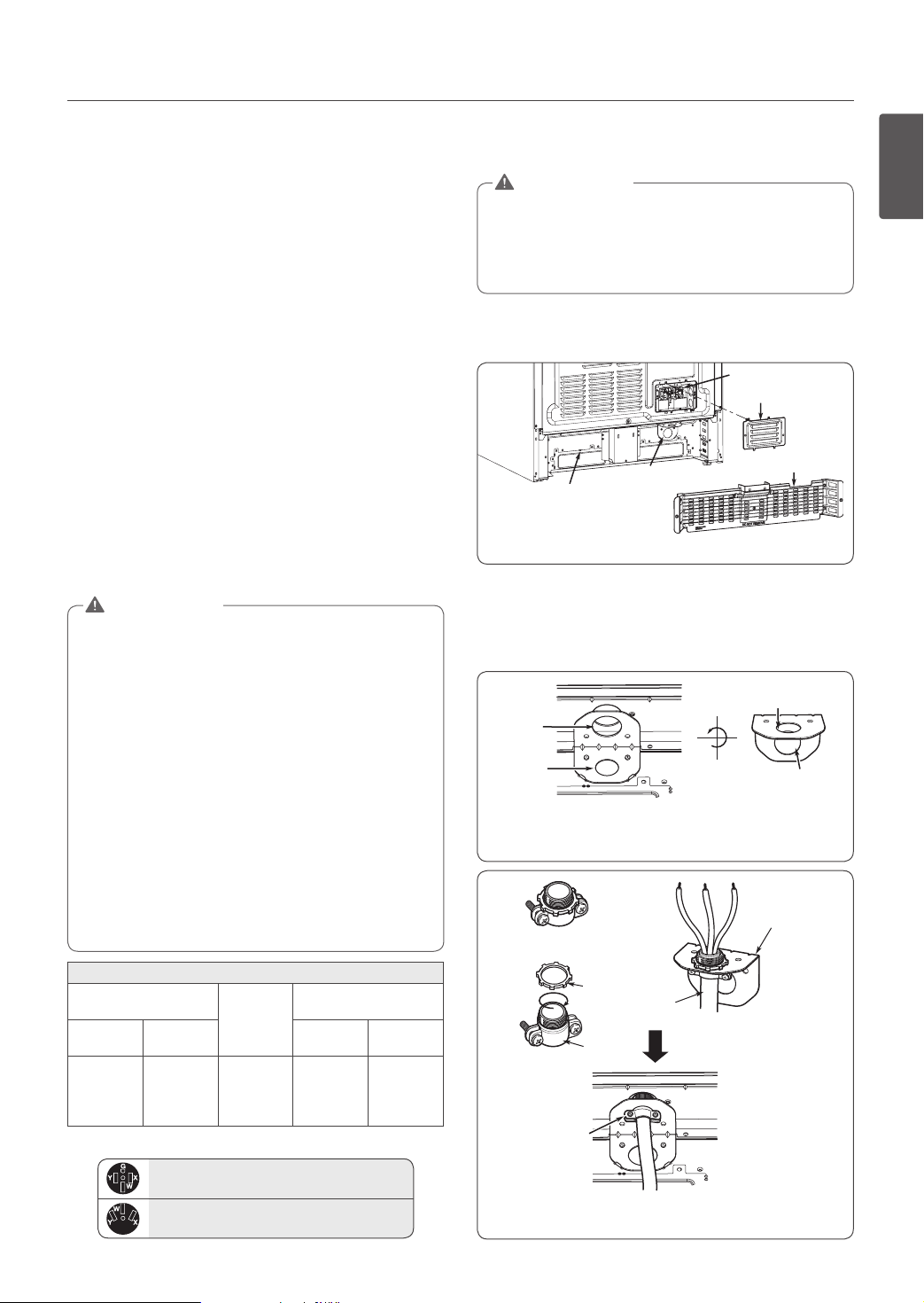
The rear access cover must be removed. Loosen the three
screws with a screwdriver. The terminal block will then be
accessible.
Terminal block
Access cover
Cord/Conduit
Rear of lower oven
connection
plate
FIGURE 4
Use the cord/conduit connection plate to install the power
cord or conduit. Leave the connection plate as installed for
power cord installations. Remove the connection plate for
conduit installations and use the smaller 1 1/8" (2.8 cm)
conduit hole instead of the 1 3/8" (3.5 cm) power cord hole.
3
1
/8"
(Cord)
1
1
/8"
(Conduit)
Remove the conduit connection plate
FIGURE 5
Strain relief
Conduit
Ring
Conduit
Body
Cord Strain
relief
strain relief hole
Reinstall the cord/conduit connection plate
FIGURE 6
Protective cover
1
(2.8cm)
Cord/Conduit
connection
plate
Assemble the
Access
cover
1
/8"
13/8"
(3.5cm)
ENGLISH
Page 8
ELECTRICAL CONNECTIONS
8
3-WIRE CONNECTION WITH A
POWER SUPPLY CORD
WARNING
• The middle (neutral or ground) wire of a 3 wire
power cord or a 3 wire conduit must be connected
to the middle post of the main terminal block. The
remaining two wires of the power cord or conduit
must be connected to the outside posts of the main
terminal connection block.
− Failure to do so can result in electrical shock,
severe personal injury or death.
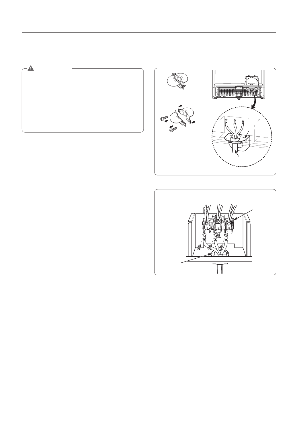
Install the power cord as follows:
For power cord installations, hook the strain relief over the
power cord hole (1
oven. Insert the power cord through the strain relief and
tighten it. (Refer to Figure 7.)
DO NOT install the power cord without a strain relief.
1. Remove the lower 3 screws from the terminal block and
retain them. (Refer to Figure 8.)
2. Insert the 3 screws through each power cord terminal ring
and into the lower terminals of the terminal block. Make
sure that the center wire (white/neutral) is connected to
the center lower position of the terminal block.
3. Tighten 3 screws securely into the terminal block.
Do not remove the ground strap connections.
4. Go to page 11.
3
/8”) located below the rear of lower
Cord strain relief
Separate strain relief
before installation
Assemble the strain relief
3
to the 1
conduit connection plate
3-wire connection
Conduit
connection
plate
Power cord
/8” opening in
FIGURE 7
Black White Red
Terminal
block
Conduit
connection plate
FIGURE 8
Page 9

4-WIRE CONNECTION WITH A
POWER SUPPLY CORD
WARNING
• Only a 4-conductor power-supply cord kit rated
120/240 volts, 50 amperes and marked for use with
ranges, with closed loop connectors or open-end
spade lugs with upturned ends, shall be used. The
middle (neutral) wire of the power cord or 4-wire
conduit must be connected to the middle post of
the main terminal block. The other two wires of
the power cord or conduit must be connected to
the outside posts of the main terminal connection
block. The 4th ground wire must be connected to
the frame of the range with the ground screw.
− Failure to do so can result in electrical shock,
severe personal injury or death.
Follow the instructions under “CONNECT RANGE CORD”
on page 7 to correctly install the strain relief.
1. Remove the lower 3 screws from the terminal block and
retain them. (Refer to Figure 9.)
2. Remove the ground screw and bend the end of the
ground strap up so the slot is over the hole of the center
screw removed in step 1.
3. Insert the ground screw into the power cord ground wire
terminal ring and secure it to the range frame.
4. Insert the 3 screws through each power cord terminal
ring and into the lower terminals of the terminal block.
Make sure that the center wire (white/neutral) is
connected to the center lower position of the terminal
block.
Tighten the 3 screws securely into the terminal block. The
center screw now attaches the bent up ground strap to
the block.
5. Go to page 11.
ELECTRICAL CONNECTIONS
9
3-WIRE CONNECTION: CONDUIT
Install the conduit as follows:
Remove the conduit connection plate from the rear of lower
oven and rotate it as shown in Figure 5. The conduit hole
1
(1
/8") must be used.
First, prepare the conduit wires as shown in Figure 10.
3 wire 4 wire
Conduit
connection
plate
or
FIGURE 10
Second, install the conduit strain relief as shown in Figure 6.
For conduit installations, purchase a strain relief and insert
it into the 1 1/8" (2.8 cm) conduit hole. Then install the
conduit through the body of the strain relief and fasten the
strain relief with its ring. Reinstall the bracket.
For conduit connections :
If the wire in the conduit is copper it must be 8 or 10 AWG
wiring.
If the wire in the conduit is aluminum it must be 6 or 8
AWG wiring.
1. Loosen the lower 3 screws from the terminal block. (Refer
to Figure 11.)
2. Insert the bare wire (white/neutral) end through the
center terminal block opening.
Do not remove ground strap connections.
3. Insert the two side bare wire ends into the lower left and
the lower right terminal block opening.
Tighten the 3 screws securely into the terminal block.
(approximately 35 - 50 IN-LB)
4. Go to page 11.
Ground
wire
ENGLISH
4-wire connection
Black White Red
Ground screw
Conduit
connection plate
FIGURE 9
Terminal
block
Bend strap up and
attach
3-wire connection
Black White Red
Terminal
block
Ground strap
Wire ends
Conduit
connection plate
FIGURE 11
Page 10

ELECTRICAL CONNECTIONS
10
4-WIRE CONNECTION: CONDUIT
WARNING
• The white middle (neutral) wire of the power
cord or 4-wire conduit must be connected to the
middle post of the main terminal block. The other
two wires of the power cord or conduit must be
connected to the outside posts of the main terminal
connection block. The fourth, ground wire (green)
must be connected to the frame of the range with
the ground screw.
− Failure to do so can result in electric shock, severe
personal injury or death.
1. Follow the instructions under “Install the conduit as
follows” on page 9 to correctly install the strain relief.
DO NOT install the conduit without a strain relief.
2. Loosen the 2 lower left and right screws from the
terminal block. (Refer to Figure 12.)
Remove the lower 2 center screws. Do not discard any
screws.
3. Remove the ground screw and bend the end of the
ground strap up so the slot is over the hole of the center
screw removed in step 2.
4. Attach the ground bare wire end to range frame and
secure it in place with the ground screw (Refer to figure
12.)
5. Insert the bare wire (white/neutral) end through the
center terminal block opening. The center screw now
attaches the bent up ground strap to the block.
6. Insert the two side bare wire ends into the left and the
right terminal block openings.
Tighten the 3 screws securely into the terminal block.
(approximately 35 - 50 IN-LB)
7. Go to page 11.
4-wire connection
Black White Red
Wire
ends
Conduit
connection plate
Ground
Screw
Terminal
block
Ground
strap
Bend strap
up and
attach
Ground
Wire
FIGURE 12
Page 11

INSTALLING THE RANGE
Replace the access cover on the back of the range. To
replace the wire cover, insert the two tabs into the openings
located below the opening and tighten the three screws.
Access cover
ANTI-TIP DEVICE INSTALLATION
WARNING
Tip - Over Hazard
A child or adult can tip the range and be
killed. Verify the anti-tip bracket has been
installed. Ensure the anti-tip bracket is
engaged when the range is moved.
Do not operate the range without the antitip bracket in place. Failure to follow these
instructions can result in death or serious
burns to children and adults.
To check visually that leveling leg is inserted into
bracket, grasp the top rear edge of the range
and carefully attempt to tilt it forward.
Anti-tip
bracket
Screw must
enter wood
or concrete
1. Locate the bracket using the template
An Anti-tip bracket is packaged with template. The
instructions include necessary information to complete
the installation.
Read and follow range installation instruction sheet
(template).
bracket
Wall plate
Leveling
leg
INSTALLING THE RANGE
Lower
range
Leg
leveler
Raise
range
Use a level to check your adjustments. Place the level
diagonally on the oven rack, and check each direction for
level.
First check direction .
After check direction .
If the level doesn’t show
level on the rack, adjust
the leveling legs with a
wrench.
level
11
FINAL INSTALLATION
•Moverangecloseenoughtotheopeningtoplugintothe
receptacle.
•Slide rangeintoposition insuring that the left backleg
slides under the anti-tip bracket. Range should sit flush
against the back wall when properly installed.
•Carefullyattempttotiprangeforwardtoinsurethatthe
anti-tip bracket is engaged properly. If properly installed,
the anti-tip bracket will prevent the range from being
tipped. If the range can be tipped, reinstall the range
until the bracket is properly engaged and the range will
not tip forward.
•Turnon electrical power.Check the range for proper
operation as described in owner’s manual.
ENGLISH
2. Level the range
Level the range by adjusting the leveling legs with a
wrench. Extending the legs slightly may also make it
easier to insert the rear leg into the anti-tip bracket.
Page 12

INSTALLING THE RANGE
12
TEST RUN
Check if the range is properly installed and run a test cycle.
1. Touch Clear/O to start test.
2. Set the elements to Hi to check that the surface heating
elements are working properly. The elements should glow
red and radiate heat, and they should cycle on and
o periodically even when set to the Hi position. This
cycling prevents the glass-ceramic from being cracked
by thermal shock.
IMPORTANT: The warm zone does not consume enough
power to glow red.
3. After checking all the surface heating elements, check
the locking system by touching Start for three seconds.
The oven door should lock and the cooktop should not
operate while the Lockout function is turned on. touch
Start for three seconds to disable Lockout.
4. Now check the ovens' operation. Touch Bake and touch
the number keys to set the upper oven temperature to
350°F. Repeat for the lower oven.
5.Theovensshouldnishpreheatingin15minutes,andthe
convection fan should operate while the lower oven is
preheating.
6. After checking the ovens' operation, turn the temperature
up to 450°F and leave the ovens on for at least an hour
to help remove any oil which might cause smoke and
odorswhenrstusingtheovens.
NOTE
Smokemay come out of the rangewhen it is rst
used.
Page 13

ÍNDICE
ÍNDICE
13
14 INSTRUCCIONES IMPORTANTES DE SEGURIDAD
16 PREPARACIÓN PARA LA INSTALACIÓN
16 Antes de comenzar
17 Dimensiones y espacios
18 CONEXIONES ELÉCTRICAS
18 Requisitos de las conexiones eléctricas
18 Cómo conectar el cable de la estufa
19 Conexión de 3 alambres con un cable de alimentación
20 Conexión de 4 alambres con un cable de alimentación
20 Conexión de 3 alambres: Conducto portacables
21 Conexión de 4 alambres: Conducto portacables
22 CÓMO INSTALAR LA ESTUFA
22 Instalación del soporte anti vuelco
22 Instalación final
23 Prueba de funcionamiento
ESPAÑOL
Page 14

INSTRUCCIONES IMPORTANTES DE SEGURIDAD
14
INSTRUCCIONES IMPORTANTES DE SEGURIDAD
Lea y siga todas las instrucciones antes de utilizar su estufa para evitar el riesgo de incendio, descarga eléctrica, lesiones
personales o daños cuando use la estufa. Esta guía no cubre todas las condiciones posibles que pueden ocurrir. Para mayor
asistencia, comuníquese con su agente de servicios o fabricante.
Este es el símbolo de alerta de seguridad. Este símbolo lo alerta sobre peligros potenciales que pueden matarlo
a lastimarlo a usted o a otros. Todos los mensajes de seguridad se encontrarán después de los símbolos de
alerta de seguridad y de las palabras "ADVERTENCIA" O "PRECAUCIÓN".
ADVERTENCIA
Este símbolo lo alerta sobre peligros o prácticas poco seguras que podrían provocar lesiones personales graves o la muerte.
PRECAUCIÓN
Este símbolo lo alerta sobre peligros o prácticas poco seguras que podrían provocar lesiones personales o daños a la
propiedad.
ADVERTENCIA
• La información de este manual se debe seguir con precisión para evitar incendios, descargas eléctricas, daños a la
propiedad, lesiones personales o muerte.
• No se pare ni se siente sobre la puerta del horno. Instale el soporte anti vuelco suministrado con la estufa.
− La estufa puede volcarse y puede provocar lesiones debido al derrame de líquidos y alimentos calientes o la estufa
misma.
− Cuando se separa la estufa de la pared por motivos de limpieza, servicio u otra razón, asegúrese de volver a embonar
correctamente el Soporte Anti Vuelco al volver a empujar la estufa contra la pared.
• Todas las estufas pueden inclinarse y provocar lesiones.
− Para evitar vuelcos accidentales de la estufa, instale un soporte anti vuelco aprobado en la pared. (Consulte la sección
“Instalación del soporte anti vuelco” de este manual y las instrucciones que vienen con el soporte.)
− Para verificar si el soporte está instalado y sujeto correctamente, incline con cuidado la estufa hacia adelante. El soporte
anti vuelco debería sujetar y evitar que la estufa se vuelque hacia adelante.
− Si, por alguna razón, usted separa la estufa de la pared, asegúrese de que el soporte anti vuelco quede sujeto cuando
vuelva a colocar la estufa contra la pared.
• Para la instalación o para mover la estufa, son necesarias dos personas. (Riesgo de peso excesivo)
− Ignorar esta advertencia puede causar daños en la espalda u otros daños.
• No utilice las manijas de la puerta del horno para tirar de la estufa, empujarla o moverla.
− Ignorar esta advertencia puede causar daños serios en la puerta del horno.
• Las instalaciones nuevas en circuitos derivados (1996 NEC) para casas rodantes, vehículos recreativos e instalaciones
donde los códigos locales no permiten la conexión a tierra a través del cable neutral requieren un cable de estufa listado
UL de cuatro conductores o una conexión de conductores de 4 cables.
• No modifique el enchufe ni el cable de alimentación. Si el enchufe no entra en el tomacorriente, debe solicitar que un
electricista calificado instale un tomacorriente adecuado.
Page 15

INSTRUCCIONES IMPORTANTES DE SEGURIDAD
15
ADVERTENCIA
• No utilice un cable de extensión para conectar con la toma de corriente.
• Este dispositivo requiere toma de tierra.
• Debe asegurarse de que el cable de alimentación no esté aplastado por la estufa ni objetos pesados.
− Ignorar esta advertencia puede causar quemaduras serias o descargas electricas.
• No retire nunca la cubierta de protección de la parte trasera inferior de la estufa.
− Ignorar esta advertencia puede causar daños serios al cable de alimentación, quemaduras serias y una descarga eléctrica.
• El cable medio (neutral o a tierra) de un cable de energía de 3 clavijas o un conducto de 3 clavijas debe conectarse a
la posición media del bloque terminal principal. Las dos clavijas restantes del cable de energía o conducto deben estar
conectados a las posiciones externas del bloque de conexión terminal principal.
− No hacerlo puede provocar una descarga eléctrica, lesiones personales graves o la muerte.
• Sólo deberá utilizarse un equipo con cable de energía de 4 conductores clasificado 120/240 voltios, 50 amperios y
marcado para utilizar con estufas con conectores de bucle cerrado o pernos de pala de extremos abiertos con bordes
elevados. La clavija media (neutral) del cable de energía o conducto de 4 clavijas debe conectarse a la posición media
del bloque terminal principal. Las otras dos clavijas del cable de energía o conducto deben conectarse a las posiciones
externas del bloque de conexión terminal principal. La cuarta clavija a tierra debe conectarse al marco de la estufa con
el tornillo a tierra.
− No hacerlo puede provocar una descarga eléctrica, lesiones personales graves o la muerte.
ESPAÑOL
PRECAUCIÓN
• Durante el procedimiento de instalación deben utilizarse guantes de seguridad.
- Si no lo hace, podría sufrir lesiones corporales.
• Debe asegurarse de que la cobertura de la pared, la encimera y los armarios junto al horno pueden aguantar la
temperatura (hasta 90°C) generada por la estufa.
- Puede provocarse decoloración, delaminación o derretimiento.
- Esta estufa ha sido diseñada para cumplir con las temperaturas máximas permitidas de gabinetes de madera de
194°F.
• Evite colocar gabinetes encima de la estufa.
• Debe instalar un extractor para la estufa que se proyecte horizontalmente un mínimo de 13cm por debajo de la parte
inferior de los gabinetes.
− Hacerlo puede reducirse el riesgo de quemaduras o incendios por inclinarse sobre los elementos de superficie calientes.
• No debe instalar la estufa en un lugar húmedo. Salpicar la estufa con agua o cualquier otro electrolito puede causar
descargas eléctricas.
• Debe evitar que se acumule grasa o materiales inflamables dentro o cerca de la estufa.
− Ignorar esta advertencia podría causar quemaduras serias.
Page 16

PREPARACIÓN PARA LA INSTALACIÓN
bracket
Leveling
leg
16
PREPARACIÓN PARA LA INSTALACIÓN
ANTES DE COMENZAR
Quite todas las cintas y materiales de embalaje antes de usar
la estufa.
Elimine todas las bolsas de plástico después de desempacar la
estufa. Nunca permita que los niños jueguen con los materiales
de empaque.
Puede descargar el manual de instalacion en: http://
www.kenmore.com
ADVERTENCIA
• La información de este manual debe seguirse al pie
de la letra para evitar riesgos de incendios, descargas
eléctricas, daños, lesiones personales, o la muerte.
ADVERTENCIA
RIESGO DE VOLCAR
Un niño o un adulto pueden volcar el aparato
y provocar su muerte. Verifique que el soporte
anti vuelco ha sido instalado. Asegúrese que el
soporte anti vuelco esté ajustado cuando mueva el
aparato. No haga funcionar el aparato sin que el
soporte anti vuelco esté ajustado. No seguir estas
instrucciones puede ser causa de muerte o graves
quemaduras en niños o adultos.
A fin de examinar visualmente que el tubo
nivelador posterior está introducido en el soporte,
tome la esquina superior posterior del aparato e
inclínela con cuidado hacia adelante.
Soporte
Anti Vuelco
HERRAMIENTAS NECESARIAS
Destornillador Phillips
Destornillador
de hoja plana
Llave de caja de
Alicates
Cinta métrica
Lápiz
1
/4”
tuercas ajustable
Gafas protectoras
PIEZAS PROVISTAS
Nivel
Llave de
Taladro
Guantes
PRECAUCIÓN
• Durante el procedimiento de instalación deben utilizarse
guantes de seguridad.
− Si no lo hace, podría sufrir lesiones corporales.
Conserve estas instrucciones junto con su manual del usuario
para cualquier consulta en el futuro.
• Al igual que cuando se utiliza cualquier artefacto que genera
calor, deben seguirse ciertas precauciones de seguridad.
• Cerciórese de que su estufa sea instalada y conectada a tierra
correctamente por un instalador o técnico de servicio calificado.
• Cerciórese de que todos los adornos o recubrimientos de la
pared que están alrededor de la estufa tienen la capacidad
de resistir el calor generado por la misma.
• Se debe evitar el uso de gabinetes de almacenamiento
encima de la estufa para no tener que alcanzarlos por encima
de los elementos de cocción.
NOTA
• Antes de instalar la estufa lea todas las instrucciones
incluidas en el manual de instalación.
• Quite toda la cinta y los materiales de empaque del horno.
• Cumpla con todos los códigos y ordenanzas vigentes.
• Siempre deje estas instrucciones con el consumidor.
• Elimine todas las bolsas de plástico después de desempacar
la estufa. Nunca permita que los niños jueguen con los
materiales de empaque.
• Puede descargar el manual de instalación en:
http://www.kenmore.com
Plantilla (1)
Manguitos de anclaje (4)
(Solamente cuando se instala el soporte anti
vuelco en pisos de concreto)
PIEZAS NO PROVISTAS
(Aprobado por la UL
para 40 0 50 AMPS)
Cable de 4 alambres o de
3 alambres
Juego de soporte anti
vuelco (1)
Pernos de fijación (4)
Tensor de alivio
(Solamente para
instalaciones con
conducto portacables)
Page 17

DIMENSIONES Y ESPACIOS
PREPARACIÓN PARA LA INSTALACIÓN
17
NOTA
GUÁRDELO PARA EL USO DEL INSPECTOR LOCAL DE
INSTALACIONES ELÉCTRICAS.
Si se va a instalar en CANADÁ, una estufa autónoma no
podrá instalarse a menos de 15/32 (12mm) de cualquier
superficie adyacente.
PRECAUCIÓN
• Debe asegurarse de que la cobertura de la pared,
la encimera y los armarios junto al horno pueden
aguantar la temperatura (hasta 90°C) generada
por la estufa.
- Puede provocarse decoloración, delaminación o
derretimiento.
- Esta estufa ha sido diseñada para cumplir con las
temperaturas máximas permitidas de gabinetes
de madera de 194°F.
ADVERTENCIA
• Para la instalación o para mover el horno, son
necesarias dos personas. (Riesgo de peso excesivo)
− Ignorar esta advertencia puede causar daños en la
espalda u otros daños.
• No utilice las manijas del horno para empujar la
estufa, moverla o tirar de ella.
− Ignorar esta advertencia puede causar daños serios
en la puerta del horno.
PRECAUCIÓN
• Evite instalar armarios directamente sobre la estufa.
• Si hay armarios instalados sobre la estufa, coloque
una campana de estufa que se proyecte en forma
horizontal un mínimo de 5 pulgadas por fuera de la
parte inferior de los armarios.
− Al hacerlo, reducirá el riesgo de quemaduras o
incendios causados al estirarse por encima de los
elementos de superficie caliente calientes de la
superficie.
ESPAÑOL
Pared
Gabinetes
4”
(10cm)
15”(38cm)
6”
6”
(15.2cm)
(15.2cm)
(23cm)
9”
11”(28cm)
4”
(10cm)
Cetro
2.5”(6.3cm)2.5”(6.3cm)
5”
(13cm)
(15.2cm)
9”
(23cm)
6”
2.5”
(6.3cm)
A = 30" (76.2 cm) Para EE.UU.
= 30" a 31" (76.2 a 78.7 cm) Para CANADÁ
FIGURA 1
FIGURA 2
DIMENSIONES MÍNIMAS (Figura 2)
* 30" (76.2 cm) de holgura mínima entre la cubierta de la placa de cocción y la base de un gabinete de madera o de
metal sin protección; o 24" (60.9 cm) como mínimo cuando la parte inferior de un gabinete de madera o de metal está
protegida por una capa de
1
/4" (6.4 mm) de cartón gris resistente al fuego y recubierta cuando menos con lámina de
acero no. 28 MSG , 0.015" (0.381 mm) de acero inoxidable, 0.024" (0.610 mm) de aluminio o 0.020" (0.508 mm) de cobre.
** 15" (38.1 cm) como mínimo entre la cubierta de los gabinetes y la parte inferior del gabinete adyacente.
Page 18

CONEXIONES ELÉCTRICAS
18
CONEXIONES ELÉCTRICAS
REQUISITOS DE LAS
CONEXIONES ELÉCTRICAS
Este artefacto deberá instalarse y conectarse a tierra en un
circuito de red por un técnico certificado, de acuerdo con
la edición más reciente del código de la National Electrical
ANSI/NFPA NO. 70
T
odo el alambrado deberá conformarse a Local y NEC. Esta
estufa requiere de un sistema eléctrico monofásico, de 3 alambres,
120/208 V C.A. o 120/240 V 60Hz. Use solamente un cable de 3
o 4 alambr
ojillo cerrado, lengüetas de pala con extremos doblados o terminales
parecidas. NO instale el cable de alimentación sin un protector.
Es necesario un cable para estufa con capacidad nominal de
120/240 V a 40 amps. Si se llegara a usar un cable de estufa
de 50 amps., deberá estar marcado como para ser utilizado en
aberturas de conexión de 13.8” (3.5 cm) de diámetro.
Este artefacto puede conectarse usando un conductor de cable
o cable de alimentación. Si se utilizan conductos portacables,
consulte la página 20. Conexiones de conductos portacables
con 3 alambres o la página 21 para las conexiones de conductos
portacables con 4 conductores.
Capacidad nominal de la estufa.
120/240 voltios
es para estufa reconocido por la UL, con terminales de
ADVERTENCIA
• Las instalaciones nuevas en circuitos derivados (1996
NEC) para casas rodantes, vehículos recreativos e
instalaciones donde los códigos locales no permiten la
conexión a tierra a través del cable neutral requieren
un cable de estufa listado UL de cuatro conductores o
una conexión de conductores de 4 cables.
• No debe modificarse el cable de alimentación ni el
enchufe. Si no se ajusta a la toma de corriente, haga que
un electricista calificado instale una toma adecuada.
• No utilice un cable de extensión para conectarlo a una
toma de corriente. Conecte el cable de alimentación y
el enchufe directamente.
• Este dispositivo requiere toma de tierra.
• Debe asegurarse de que el cable de alimentación no
está aplastado por la estufa ni objetos pesados.
− Ignorar esta advertencia puede causar quemaduras
serias o descargas eléctricas.
Clasificación nominal especificada para el juego del cable de alimentación
Vatios
3 alambres
8,750 -
16,500
16,501 -
22,500
120/208 voltios
3 alambres
7,801 - 12,500
12,501 -
18,500
3, Tipos de tomacorriente de pared de 4 alambres.
Tomacorriente de 4 alambres (14-50R)
Clasificación
nominal
especificada para
el juego de cable
de alimentación,
amperios
40 o 50 A501 3/8”
abertura de conexión de la estufa
alimentación
Diámetro (en pulgadas) de la
Cable de
1 3/4”
Conducto
portacables
1 1/8”
1 3/8”
CÓMO CONECTAR EL CABLE DE
LA ESTUFA
ADVERTENCIA
• No ponga en funcionamiento la estufa sin que la cubierta
protectora de la parte trasera del horno inferior esté en su lugar.
− Hacerlo puede causar graves daños al cable de
alimentación, lo que puede generar quemaduras
graves o descargas eléctricas.
Debe quitarse la cubierta de acceso posterior. Use un
destornillador para aflojar los tres tornillos. Entonces se podrá
tener acceso a un bloque de terminales.
Bloque de terminales
Cubiertas de acceso
Cubierta protectora
Access
cover
Parte trasera del
horno inferior
Placa de conexión
para conectar
a conductos
portacables
FIGURA 4
Utilice la placa de conexión del cable/conducto para instalar el cable
de alimentación o el conducto. Deje la placa de conexión según estaba
instalada, para las instalaciones del cable de alimentación. Retire la placa
deconexiónparalasinstalacionesdeconductosyutiliceeloriciopara
conductomáspequeñode11/8pulgadas(2,8cm),enlugardeloricio
para cable de alimentación de 1 3/8 pulgadas (3,5 cm).
1
1
/8" (2,8cm)
3
1
/8"
(Cable)
1
/8"
1
(Conducto
portacable)
13/8" (3,5cm)
Quite la placa de conexión de conductos portacables
FIGURA 5
Placa de conexión
para conectar a
conductos portacables
Tensor de alivio
Anillo
Conducto
portacable
Cuerpo
Strain relief
Ensamble el orificio
del tensor de alivio
Tomacorriente de 3 alambres (10-50R)
FIGURA 3
Vuelva a instalar la placa de conexión para conectar a conductos portacables
FIGURA 6
Page 19

CONEXIONES ELÉCTRICAS
19
CONEXIÓN DE 3 ALAMBRES CON
UN CABLE DE ALIMENTACIÓN
ADVERTENCIA
• El cable medio (neutral o a tierra) de un cable de
energía de 3 clavijas o un conducto de 3 clavijas
debe conectarse a la posición media del bloque
terminal principal. Las dos clavijas restantes del
cable de energía o conducto deben estar conectados
a las posiciones externas del bloque de conexión
terminal principal.
- No hacerlo puede provocar una descarga eléctrica,
lesiones personales graves o la muerte.
Instale el cable de alimentación como
sigue:
Para las instalaciones del cable de alimentación, enganche
el tensor de alivio al orificio del cable de alimentación
3
(1
/8”(3.5 cm)) ubicado debajo de la parte posterior del
horno inferior. Inserte el cable de alimentación a través del
tensor de alivio y apriételo. (Consulte la Figura 7.)
NO instale el cable de alimentación sin un protector.
1. Quite los tres tornillos inferiores del bloque de terminales
y consérvelos. (Ver Figura 8).
2. Introduzca los 3 tornillos a través del anillo de cada
terminal del cable de energía y dentro de las terminales
inferiores del bloque de terminales. Verifique que el
cable central (blanco/neutral) esté conectado en la
posición inferior central del bloque de terminales.
3. Ajuste bien los 3 tornillos al bloque de terminales.
No retire las conexiones de descarga a tierra.
4. Diríjase a la página 22.
Tensor de alivio
Separe el aliviador de
tensión antes de instalarlo.
Monte el aliviador de tensión
en el orificio de 1
de la placa de conexión del
conducto portacables
Conexión de 3 alambres
Placa de conexión
para conectar
3
/8” (3.5 cm)
Negro Blanco Rojo
ESPAÑOL
Placa de conexión
para conectar a
conductos
portacables
Cable de alimentación
FIGURA 7
Bloque de
terminales
FIGURA 8
Page 20

CONEXIONES ELÉCTRICAS
20
CONEXIÓN DE 4 ALAMBRES CON
UN CABLE DE ALIMENTACIÓN
ADVERTENCIA
•
Sólo deberá utilizarse un equipo con cable de energía de
4 conductores clasicado 120/240 voltios, 50 amperios
y marcado para utilizar con estufas con conectores de
bucle cerrado o pernos de pala de extremos abiertos
con bordes elevados. La clavija media (neutral)
del cable de energía o conducto de 4 clavijas debe
conectarse a la posición media del bloque terminal
principal. Las otras dos clavijas del cable de energía
o conducto deben conectarse a las posiciones externas
del bloque de conexión terminal principal. La cuarta
clavija a tierra debe conectarse al marco de la estufa
con el tornillo a tierra.
- No hacerlo puede provocar una descarga eléctrica,
lesiones personales graves o la muerte.
Para instalar correctamente el tensor de alivio, siga las
instrucciones “CÓMO CONECTAR EL CABLE DE LA
ESTUFA” en la página 18.
1. Quite los tres tornillos inferiores del bloque de terminales
y consérvelos. (Ver Figura 9).
2. Retire el tornillo de conexión a tierra y doble el extremo
de la correa de conexión a tierra, para que la ranura
quede sobre el orificio del tornillo central que retiró en
el paso 1.
3. Introduzca el tornillo a tierra en el anillo de terminal de
tierra del cable de energía y fíjelo al marco.
4. Introduzca los 3 tornillos a través de los anillos de
las terminales del cable de energía y dentro de las
terminales inferiores del bloque de terminales. Verifique
que el cable central (blanco/neutral) esté conectado en
la posición inferior central del bloque de terminales.
Ajuste los 3 tornillos de manera segura al bloque de
terminales. El tornillo central ahora fija la correa de
conexión a tierra, plegada hacia arriba, al bloque.
5. Diríjase a la página 22.
Conexión de 4 alambres
Negro Blanco Rojo
Bloque de
terminales
Cinta de
tierra
CONEXIÓN DE 3 ALAMBRES:
CONDUCTO PORTACABLES
Instale el conducto portacables de la
manera siguiente:
Quite la placa de conexión de conductos portacables de
la parte posterior del horno inferior y de vuelta como se
muestra en la figura 5. Debe usarse el orificio de conducto
portacables (1
En primer término, prepare los cables del conducto como
puede verse en la Figura 10.
3 alambres 4 alambres
Placa de
conexión para
conectar a conductos
portacables
En segundo lugar, instale el portacables del conducto,
como se muestra en la Figura 6.
Para instalaciones de conductos, adquiera un portacables
e insértelo en el orificio correspondiente de 1 1/8 pulgadas
(2.8 cm). Luego, instale el conducto a través del cuerpo del
portacables y ajústelo con su anillo. Vuelva a instalar el
soporte.
Para la conexión de conductos portacables :
Si el cable del conducto es cobre, la conexión eléctrica
debe ser de 8 o 10 AWG.
Si el cable del conducto es aluminio, la conexión eléctrica
debe ser de 6 o 8 AWG.
1. Afloje los 3 tornillos inferiores del bloque de terminales.
(Ver Figura 11).
2. Introduzca el extremo del cable desnudo (blanco/
neutral) a través del centro del orificio del bloque de
terminales.
No quite las conexiones de descarga a tierra.
3. Introduzca los dos extremos de cable desnudo en los
orificios del bloque de terminales inferiores izquierdo
y derecho. Ajuste bien los 3 tornillos en el bloque de
terminales (aproximadamente 35 - 50 pul/lb)
4. Diríjase a la página 22.
Conexión de 3 alambres
1
/8"(2.8 cm)).
Negro Blanco Rojo
Alambre
de tierra
o
FIGURA 10
Bloque de
terminales
Tornillo de tierra y
arandela
Pliegue la correa
hacia arriba y
ajuste
Placa de conexión para conectar
a conductos portacables
FIGURA 9
Extremos de
los cables
Placa de
conexión para conectar a
conductos portacables
FIGURA 11
Page 21

CONEXIONES ELÉCTRICAS
21
CONEXIÓN DE 4 ALAMBRES:
CONDUCTO PORTACABLES
ADVERTENCIA
• El hilo medio (neutro) del cable de alimentación o
conducto de 4 hilos se debe conectar al poste medio
del bloque de terminales principal. Los otros dos
hilos del cable de alimentación o del conducto se
deben conectar a los postes exteriores del bloque de
terminales principal. El cuarto cable a tierra (verde) se
debe conectar al marco de la estufa con el tornillo de
conexión a tierra.
− El no hacerlo podría causar lesiones personales
graves, descargas eléctricas o la muerte.
1. Siga las instrucciones de “Instale el conducto portacables
de la manera siguiente” de la página 20 para instalar el
aliviador de tensión de manera correcta.
NO instale el conducto sin un protector. No descarte
ningún tornillo.
2. Afloje los 2 tornillos inferiores izquierdo y derecho del
bloque de terminales. (Ver Figura 12).
Quite los 2 tornillos centrales inferiores.
3. Retire el tornillo de conexión a tierra y doble el extremo
de la correa de conexión a tierra, para que la ranura
quede sobre el orificio del tornillo central que retiró en
el paso 2.
4. Conecte el extremo del cable desnudo con conexión a
tierra al marco y asegúrelo en su lugar con el tornillo a
tierra. (Ver Figura 12).
5. Introduzca el extremo del cable desnudo (blanco/
neutral) a través del orificio central del bloque de
terminales. El tornillo central ahora fija la correa de
conexión a tierra, plegada hacia arriba, al bloque.
6. Introduzca los dos extremos de cable desnudo en los
orificios del bloque de terminales izquierdo y derecho.
Ajuste bien los 3 tornillos en el bloque de terminales
(aproximadamente 35 - 50 pul./lb).
7. Diríjase a la página 22.
Conexión de 4 alambres
Negro Blanco Rojo
Extremos
de los
cables
Placa de
conexión para conectar
a conductos portacables
Tornillo de
tierra y
arandela
ESPAÑOL
Bloque de
terminales
Cinta de
tierra
Pliegue la
correa hacia
arriba y
ajuste
Alambre
de tierra
FIGURA 12
Page 22

CÓMO INSTALAR LA ESTUFA
bracket
Leveling
leg
Anti Vuelco
22
CÓMO INSTALAR LA ESTUFA
Vuelva a colocar la cubierta de acceso en la parte
posterior de la estufa. Para cambiar la cubierta del cable,
inserte las dos pestañas en las aberturas situadas bajo la
puerta y apriete los tres tornillos.
Bajar la
estufa
Cubierta de acceso
INSTALACIÓN DEL SOPORTE
ANTI VUELCO
ADVERTENCIA
RIESGO DE VOLCAR
Un niño o un adulto pueden volcar el aparato
y provocar su muerte. Verifique que el soporte
anti vuelco ha sido instalado. Asegúrese que el
soporte anti vuelco esté ajustado cuando mueva
el aparato. No haga funcionar el aparato sin
que el soporte anti vuelco esté ajustado. No
seguir estas instrucciones puede ser causa de
muerte o graves quemaduras en niños o adultos.
A fin de examinar visualmente que el tubo
nivelador posterior está introducido en el soporte,
tome la esquina superior posterior del aparato e
inclínela con cuidado hacia adelante.
Soporte anti vuelco
El tornillo debe
introducirse en la
madera o en el
concreto.
1. Ubique el soporte utilizando la plantilla.
La plantilla viene empacada con cada soporte anti
vuelco. Las instrucciones incluyen la información
necesaria para llevar a buen término la instalación.
Lea y obedezca el contenido de la hoja de
instrucciones (plantilla) de la estufa.
2. Nivele la estufa
Nivele la estufa ajustando las patas niveladoras con
una llave de tuercas. Si extiende las patas ligeramente,
podría ser más fácil insertar la pata trasera en el
soporte anti vuelco.
Soporte
Placa de pared
Nivelador
de patas
Elevar la
estufa
Utilice un nivel para comprobar los ajustes. Coloque el nivel
diagonalmente sobre la rejilla del horno y compruebe el
nivelado en todas las direcciones.
Primero verifique la
Nivel
dirección .
Después verifique la
dirección .
Si el nivel no muestra que
la parrilla está nivelada,
ajuste las patas niveladoras
con una llave de tuercas.
INSTALACIÓN FINAL
•Acerquelaestufalosuficientealaaberturaparapoder
enchufarla en el tomacorriente.
•Deslice la estufa en posición asegurándose de que la
pata trasera izquierda se desliza bajo el soporte anti
vuelco. Cuando esté instalada correctamente, la estufa
debe descansar plano contra la pared posterior.
•Intentevolcar con cuidado la estufa hacia adelante
para asegurarse de que el soporte anti vuelco está bien
colocado. Si se ha instalado adecuadamente, el soporte
anti vuelco impedirá que la estufa pueda volcarse hacia
delante.
Si la estufa puede inclinarse, vuelva a colocar la estufa
hasta que el soporte este debidamente colocado y la
estufa no se incline hacia adelante.
•Enciendala alimentación deenergíaeléctrica. Verifique
que la estufa está orientada correctamente tal como se
describe en el manual del propietario.
Page 23

PRUEBA DE FUNCIONAMIENTO
Veriquequelaestufaestébieninstaladayrealiceunciclo
de prueba.
CÓMO INSTALAR LA ESTUFA
23
1. Presione Clear/O para iniciar la prueba.
2.Congurelos elementos de supercie caliente en Hi
(alto) para vericar que los elementos de supercie
caliente funcionen correctamente. Los elementos de
supercie caliente deben emitir un brillo rojo e irradiar
calor y deben cumplir el ciclo de encendido y apagado
periódicamente,inclusocuandoesténconguradasen la
posición Hi (alto). Este ciclo evita que la vitrocerámica se
quiebre debido al choque térmico.
IMPORTANTE: La zona de calentamiento no consume
energíasucientecomoparaemitirunbrillorojo.
3.Luego de revisar todos los elementos de supercie
caliente,verique el sistema de bloqueo tocando el
botón Start (Inicio) durante tres segundos. La puerta del
horno debe bloquearse y la placa de cocción no debe
funcionar mientras que la función Lockout (Bloqueo) está
encendida. Presione el botón Start (Inicio) durante tres
segundos para desactivar el bloqueo.
4.Ahora veriqueel funcionamiento del horno. Presione
Bake (Hornear) y presione las teclas numéricas para
congurarla temperaturadel horno superior a 350 °F.
Repita el procedimiento para el horno inferior.
ESPAÑOL
5. El horno debe terminar de precalentarse en 15 minutos y
el ventilador de convección debe funcionar mientras el
horno se está precalentando.
6. Después de controlar el funcionamiento del horno, suba
la temperatura a 450 °F y deje el horno encendido
durante una hora, como mínimo, para ayudar a remover
cualquier resto de aceite que pudiera causar humo y
olores al usar el horno por primera vez.
NOTA
Cuando la estufa se usa por primera vez, podría salir
humo.
Page 24

1-844-553-6667
In Canada 1-800-469-4663
Sears Parts & Repair Service Center
1-800-488-1222 1-800-469-4663
1-800-827-6655
1-888-SU-HOGAR
1-800-361-6665
1-800-LE-FOYER
®
MC
Page 25

Universal Keywords: Div22 Src721 LG LGE Mechtech
Document Specific Keywords: Installation Instructions
Date: 110816
Document Name: MFL69645901in
Subject: LG Electric Range 721.9604 Installation Instructions
Models: 721.96047610 721.96043610 72196047610 72196043610 MFL69645901
 Loading...