

Kenmore Elite 153.331010, Elite 153.331000, Elite 153.331000 HA Use & Care Manual

http://waterheatertimer.org/New-water-heater-ideas.html
Use & Care Guide
Model No.
153.331010 25 U.S. Gal (94.6 Litres)
For installation at elevations from 0-3,500 ft. (0-1,067m).
153.331000 HA 25 U.S. Gal (94.6 Litres)
For installation at elevations from 3,501 - 6,500 ft. (1,067 - 1,981m).
Kenmore Elite
®
Hybrid Gas Water Heater
For potable water heating only.
Not suitable for space heating.
Not for use in mobile homes.
INSTALLER: Affi x these instructions to or near
the water heater.
OWNER: Retain these instructions for future
reference.
FOR YOUR SAFETY: An odorant is added to
the gas used by this water heater.
IMPORTANT: For installations above 3,500
feet above sea level, verify the proper high
altitude water heater model is installed or the
proper circuit board has been ordered and
installed. See High Altitude section of manual
for further details.
P/N 320169-001 (0611)
Sears Brands Management Corporation,
Hoffman Estates, IL 60179 U.S.A.
www.kenmore.com
www.sears.com

SAFE INSTALLATION, USE AND SERVICE
Your safety and the safety of others is extremely important in the installation, use and servicing of this water heater.
Many safety-related messages and instructions have been provided in this manual and on your own water heater to warn you and
others of a potential injury hazard. Read and obey all safety messages and instructions throughout this manual. It is very important
that the meaning of each safety message is understood by you and others who install, use or service this water heater.
All safety messages will generally tell you about the type of hazard, what can happen if you do not follow the
safety message and how to avoid the risk of injury.
The California Safe Drinking Water and Toxic Enforcement Act requires the Governor of California to publish a
list of substances known to the State of California to cause cancer, birth defects, or other reproductive harm,
and requires businesses to warn of potential exposure to such substances.
• WARNING: This product contains a chemical known to the State of California to cause cancer, birth defects,
or other reproductive harm.
• This appliance can cause low-level exposure to some of the substances listed in the act.
IMPORTANT DEFINITIONS
• Qualifi ed Installer or Service Agency: Installation and service of this water heater requires ability equivalent to that
of a Qualifi ed Agency (as defi ned by ANSI below) in the fi eld involved. Installation skills such as plumbing, air supply ,
venting, gas supply, electrical supply are required in addition to electrical testing skills when performing service.
• ANSI Z223.1 2006 Sec. 3.3.83: “Qualifi ed Agency” - “Any individual, fi rm, corporation or company that either in person
or through a representative is engaged in and is responsible for (a) the installation, testing or replacement of gas piping
or (b) the connection, installation, testing, repair or servicing of appliances and equipment; that is experienced in such
work; that is familiar with all precautions required; and that has complied with all the requirements of the authority
having jurisdiction.”.
• Gas Supplier: The Natural Gas or Propane Utility or service who supplies gas for utilization by the gas burning appliances
within this application. The gas supplier typically has responsibility for the inspection and code approval of gas piping
up to and including the Natural Gas meter or Propane storage tank of a building.
2

GENERAL SAFETY
3

GENERAL SAFETY
WARNING
• Before servicing the water heater, make
sure the water heater is unplugged from
the electrical supply.
• Label all wires prior to disconnection
when servicing controls. Wiring error can
cause improper and dangerous operation. Verify proper operation after
servicing.
• Failure to do this could result in death,
serious bodily injury, or property
damage.
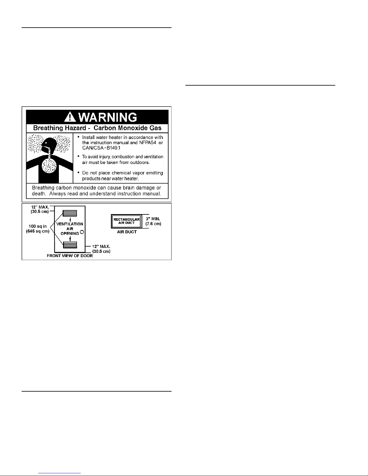
WARNING
Breathing Hazard - Carbon Monoxide Gas
• Install vent system In accordance with codes.
• Do not operate water heater if flood damaged.
• Standard model is fitted for operation at altitudes
up to 3,500 ft. (1,067m). High Altitude model is
suitable for altitudes between 3,501 to 6,500 ft.
(1,067m and 1,981m). Specific accessory kits are
required for installations above 6,500 ft. (1,981m).
• Do not operate if soot buildup is present.
• Do not obstruct water heater air intake with
insulating jacket.
• Do not place chemical vapor emitting products
near water heater.
• Gas and carbon monoxide detectors are
available.
• No vent damper installation is compatible with
this power vented water heater.
• Do not elevate the condensate hose on the
bottom of the water heater above the bracket
attached to the side of the unit. This must be true
for the entire length of the hose including the exit
into an appropriate drain.
• Condensate lines must be free and clear of debris
and must not allow back flow through the hose.
The condensate lines must be able to flow freely
to an appropriate drain.
• Do not allow condensate lines to become crimped
closed.
• Analyze the entire vent system to make sure that
condensate will not become trapped in a section
of vent pipe and therefore reduce the open cross
sectional area of the vent.
Breathing carbon monoxide can cause brain damage or death.
Always read and understand instruction manual.
DANGER
FLAMMBLE
Vapors from flammable
liquids may explode and
catch fire causing death or
severe burns.
Do not use or store
flammable products such as
gasoline, solvents or adhesives in the same room or
area near the water heater.
Keep flammable products:
1. far away from heater,
2. in approved containers,
3. tightly closed and
4. out of children's reach.
Installation: Do not install the water heater where flammable
products will be stored or used. It must be installed a minimum
of 18 in. (45cm) above the floor if installed in a residential
garage. This will reduce, but not eliminate, the risk of flammable
vapors bein g i g n ited b y t h e m a i n b u r n e r o r s p a r k igniter.
Flammable Vapors
Water heater has a main
burner and spark generator.
The spark generator:
1. can be triggered at any
time and
2. the spark will ignite
flammable vapors.
Vapors:
1. cannot be seen,
2. are heavier than air,
3. go a long way on the floor
and
4. can be carried from other
rooms to the the
electodes by air currents.
4

TABLE OF CONTENTS
SAFE INSTALLATION, USE AND SERVICE 2
GENERAL SAFETY 3
PRODUCT WARRANTY 6
INTRODUCTION 8
Get To Know Your Water Heater - Gas Models. . . . . 9
INSTALLATION CONSIDERATIONS 10
Rough In Dimensions . . . . . . . . . . . . . . . . . . . . . . . 10
Water Piping - Mixing Valve Usage. . . . . . . . . . . . . 12
Facts To Consider About Location. . . . . . . . . . . . . . 13
Handle Installation. . . . . . . . . . . . . . . . . . . . . . . . . . 14
Earthquake Zones. . . . . . . . . . . . . . . . . . . . . . . . . . 15
Combustion Air And Ventilation. . . . . . . . . . . . . . . . 17
Appliances In Unconfi ned Spaces . . . . . . . . . . . . . 17
Appliances In Confi ned Spaces . . . . . . . . . . . . . . . 17
Chemical Vapor Corrosion . . . . . . . . . . . . . . . . . . . 19
Water Piping . . . . . . . . . . . . . . . . . . . . . . . . . . . . . . 19
Closed Water Systems . . . . . . . . . . . . . . . . . . . . . . 19
Thermal Expansion. . . . . . . . . . . . . . . . . . . . . . . . . 19
Hard Water . . . . . . . . . . . . . . . . . . . . . . . . . . . . . . . 20
Temperature-pressure Relief Valve. . . . . . . . . . . . . 20
Gas Piping. . . . . . . . . . . . . . . . . . . . . . . . . . . . . . . . 22
Sediment Traps. . . . . . . . . . . . . . . . . . . . . . . . . . . . 22
Gas Line Purging . . . . . . . . . . . . . . . . . . . . . . . . . . 23
High Altitude Installations . . . . . . . . . . . . . . . . . . . . 23
Flooding/freezing. . . . . . . . . . . . . . . . . . . . . . . . . . . 23
Filling The Water Heater. . . . . . . . . . . . . . . . . . . . . 23
Venting . . . . . . . . . . . . . . . . . . . . . . . . . . . . . . . . . . 24
Vent Pipe Techniques . . . . . . . . . . . . . . . . . . . . . . . 24
Planning The Vent System . . . . . . . . . . . . . . . . . . . 25
Installation Of Vent System. . . . . . . . . . . . . . . . . . . 26
Vent Terminal Installation, Sidewall. . . . . . . . . . . . . 26
Installation Of Vent System, Sidewall . . . . . . . . . . . 27
Installation Of Vertical Vent System . . . . . . . . . . . . 28
Vent Pipe Preparation. . . . . . . . . . . . . . . . . . . . . . . 28
Connection To Vent Pipe. . . . . . . . . . . . . . . . . . . . . 31
Condensate. . . . . . . . . . . . . . . . . . . . . . . . . . . . . . . 31
US. Power Vent. . . . . . . . . . . . . . . . . . . . . . . . . . . . 32
Electrical Connections. . . . . . . . . . . . . . . . . . . . . . . 33
Calibration. . . . . . . . . . . . . . . . . . . . . . . . . . . . . . . . 33
OPERATING INSTRUCTIONS 34
Display Panel . . . . . . . . . . . . . . . . . . . . . . . . . . . . . 34
Wiring Diagram . . . . . . . . . . . . . . . . . . . . . . . . . . . . 36
Lighting Instructions . . . . . . . . . . . . . . . . . . . . . . . . 37
Temperature Regulation . . . . . . . . . . . . . . . . . . . . . 38
Unique Hybrid Features . . . . . . . . . . . . . . . . . . . . . 39
Temperature Regulation . . . . . . . . . . . . . . . . . . . . . 41
Constant Output Temperature Control . . . . . . . . . . 42
Start Up Conditions. . . . . . . . . . . . . . . . . . . . . . . . . 42
Operational Conditions . . . . . . . . . . . . . . . . . . . . . . 42
MAINTENANCE 43
Housekeeping. . . . . . . . . . . . . . . . . . . . . . . . . . . . . 43
Venting System Inspection . . . . . . . . . . . . . . . . . . . 43
Flood Damage. . . . . . . . . . . . . . . . . . . . . . . . . . . . . 43
Anode Rod Inspection. . . . . . . . . . . . . . . . . . . . . . . 43
Anode Rod Replacement . . . . . . . . . . . . . . . . . . . . 44
Temperature-pressure Relief Valve Operation . . . . 44
Motors. . . . . . . . . . . . . . . . . . . . . . . . . . . . . . . . . . . 44
Snow Accumulation. . . . . . . . . . . . . . . . . . . . . . . . . 45
Cleaning The Inlet Water Filter . . . . . . . . . . . . . . . . 45
Cleaning The Heat Engine . . . . . . . . . . . . . . . . . . . 45
Flushing The Heat Exchanger (Lime Build-up). . . . 45
Draining The Tank . . . . . . . . . . . . . . . . . . . . . . . . . . 46
Fault Indication And Error Codes . . . . . . . . . . . . . . 46
Diagnostic Display. . . . . . . . . . . . . . . . . . . . . . . . . . 47
TROUBLESHOOTING 52
Service . . . . . . . . . . . . . . . . . . . . . . . . . . . . . . . . . . 54
Leakage Checkpoints . . . . . . . . . . . . . . . . . . . . . . . 54
Replacement Parts . . . . . . . . . . . . . . . . . . . . . . . . . 55
Parts Identifi cation. . . . . . . . . . . . . . . . . . . . . . . . . . 57
Notes. . . . . . . . . . . . . . . . . . . . . . . . . . . . . . . . . . . . 58
Model Number _________________________________________
Serial Number __________________________________________
Installation Information:
Date Installed __________________________________________
Company’s Name _______________________________________
Street or P.O. Box _______________________________________
City, State, and Zip Code _________________________________
Phone Number ____________ Plumber’s Name _______________
5
Fill out and keep with water heater.
IMPORTANT INFORMATION

PRODUCT WARRANTY
Kenmore Elite® Hybrid Gas Water Heater Warranty
For six years from the date of purchase, if this water heater is installed and operated in a single-family home in accordance with the owner’s
manual instructions and all local applicable plumbing codes, Sears will:
1. Supply free water heater parts for those that are defective in material or workmanship.
2. Supply a free water heater for one that develops a tank leak. See notes below also.
For the second through sixth year from the purchase date, you must pay the labor cost for installation of parts or water heater.
For commercial, institutional, industrial or residential use by two or more families, the above limited warranty is only for one year.
If governmental regulations prohibit Sears from furnishing a comparable model replacement water heater under this warranty, Sears will
furnish a new water heater of comparable output as permitted by such governmental regulations; however, the Owner will be charged for the
additional cost associated with the changes made to comply with such governmental regulations.
Replacements furnished under this warranty do not carry a new warranty and are only covered by the unexpired portion of the original
warranty.
CONDITIONS AND EXCEPTIONS
This warranty shall apply only when the water heater is installed and operated in accordance with 1) all local fi re codes and plumbing codes,
ordinances, and regulations. 2) the printed instructions provided with it, 3) good industry practices, and 4) proper safety practices such as
but not limited to a properly sized drain pan if installed in an area where leakage from connections of the tank would result in damage to the
area adjacent to the heater. In addition, a new temperature and pressure relief valve, certifi ed by the Canadian Standards Association must
have been properly installed and piped to the nearest drain.
This warranty shall apply only when the heater is:
• not subjected to excessive water pressure fl uctuations and not subject to an operating pressure greater than 150 P.S.I.
• fi lled with potable water, free to circulate at all times and with the tank free of damaging water sediment or scale deposits.
• used in a non-corrosive and non-contaminated atmosphere.
• sized in accordance with proper sizing techniques for residential water heaters.
• bearing a rating plate which has not been altered, defaced or removed.
• used in an open system or in a closed system with a properly sized and installed thermal expansion tank.
• fi red at the factory rated input using the fuel stated on the face of the rating plate.
• operated with the inner and outer doors in place.
• maintained in accordance with the instructions printed in the manual included with the heater.
• used in a water supply with less than 12 grains per gallon (200 mg/L) of hardness, is not acidic or otherwise impure.
Problems resulting from scale formation are not covered by the warranty.
Any accident to the water heater or any part thereof (including freezing, fi re, fl oods, or lightning), any misuse, abuse, or alteration of it, any
operation of it in a modifi ed form, or any attempt to repair tank leaks or parts, will void this warranty.
For the fi rst year from the date of purchase, Sears will, free of charge, supply and install new water heater parts for defective ones or a new
water heater for one that develops a leak.
To obtain warranty service, call 1-800-4-MY-HOME
This warranty applies only while this product is in use in the United States.
This warranty gives you specifi c legal rights, and you may have other rights which vary from state to state.
SEARS BRANDS MANAGEMENT CORPORATION, Hoffman Estates, IL 60179
The price of your water heater does not include a free checkup service call. On water heater installations arranged by Sears, Sears
warrants the installation.
A charge will be made on service calls due to poor or incomplete installation. These include:
a. Adjusting thermostat b. Condensation c. Leaks in pipes or fi ttings
6
1-YEAR EXCLUSIVE KENMORE LABOR WARRANTY
WARRANTY SERVICE
®
(1-800-469-4663).

Master Protection Agreements
Congratulations on making a smart purchase. Your new Kenmore
product is designed and manufactured for years of dependable
operation. But like all products, it may require preventive maintenance
or repair from time to time. That’s when having a Master Protection
Agreement can save you money and aggravation.
The Master Protection Agreement also helps extend the life of your
new product. Here’s what the Agreement* includes:
• Parts and labor needed to help keep products operating properly
under normal use, not just defects. Our coverage goes well
beyond the product warranty. No deductibles, no functional
failure excluded from coverage - real protection.
• Expert service by a force of more than 10,000 authorized Sears
service technicians, which means someone you can trust will
be working on your product.
• Unlimited service calls and nationwide service, as often as
you want us, whenever you want us.
• “No-lemon” guarantee – replacement of your covered product
if four or more product failures occur within twelve months.
• Product replacement if your covered product can’t be fi xed.
• Annual Preventive Maintenance Check at your request – no
extra charge.
• Fast help by phone - we call it Rapid Resolution - phone
support from a Sears representative on all products. Think of
us as a “talking owner’s manual.”
• Power surge protection against electrical damage due to power
fl uctuations.
®
• $250 Food Loss Protection annually for any food spoilage that
is the result of mechanical failure of any covered refrigerator or
freezer.
• Rental reimbursement if repair of your covered product takes
longer than promised.
• 10% discount off the regular price of any non-covered repair
service and related installed parts.
Once you purchase the Agreement, a simple phone call is all that it
takes for you to schedule service. Y ou can call anytime day or night,
or schedule a service appointment online. The Master Protection
Agreement is a risk free purchase. If you cancel for any reason
during the product warranty period, we will provide a full refund. Or,
a prorated refund anytime after the product warranty period expires.
Purchase your Master Protection Agreement today!
Some limitations and exclusions apply. For prices and additional
information in the U.S.A. call 1-800-827-6655.
* Coverage in Canada varies on some items. For full details,
call Sears Canada at 1-800-361-6665.
Sears Installation Service
For Sears professional installation of home appliances, garage door
openers, water heaters, and other major home items, in the U.S.A.
or Canada call 1-800-4-MY-HOME
®
.
7

INTRODUCTION
Thank You for purchasing this water heater. Properly
installed and maintained, it should give you years of trouble
free service.
Abbreviations Found In This Instruction Manual:
• CSA - Canadian Standards Association
• ANSI - American National Standards Institute
• NFPA - National Fire Protection Association
• ASME - American Society of Mechanical Engineers
• GAMA - Gas Appliance Manufacturer’s Association
• UL - Underwriters Laboratories Inc.
This gas-fi red water heater is design certifi ed by CSA
International under American National Standard/CSA
Standard for Gas Water Heaters ANSI Z21.10.3 • CSA
4.3 (current edition).
PREPARING FOR THE INSTALLATION
Read the “General Safety” section, of this manual
1.
first and then the entire manual carefully. If you
don’t follow the safety rules, the water heater will not
operate properly. It could cause DEATH, SERIOUS
BODILY INJURY AND/OR PROPERTY DAMAGE.
This manual contains instructions for the installation,
operation, and maintenance of the gas-fi red water
heater. You must read and be aware of the warnings
placed throughout the manual. All warnings and all
instructions are essential to the proper operation of
the water heater and your safety . Since we cannot put
everything on the fi rst few pages, READ THE ENTIRE
MANUAL BEFORE ATTEMPTING TO INSTALL OR
OPERATE THE WATER HEATER.
The installation must conform with these instructions
2.
and the local code authority having jurisdiction. In
the absence of local codes, the installation must
comply with the current editions of the National Fuel
Gas Code, ANSI Z223.1/NFPA 54 and the National
Electrical Code, NFP A 70. Documents are available
from:
Canadian Standards Association,
5060 Spectrum Way,
Mississauga, Ontario, Canada
L4W 5N6
Carefully plan the place where you are going to put
5.
the water heater. Correct combustion, vent action, and
vent pipe installation are very important in preventing
death from possible carbon monoxide poisoning and
fi res (see Figures 1 and 3). Examine the location to
ensure the water heater complies with the “Facts to
Consider About Location” section in this manual.
For California installation this water heater must be
6.
braced, anchored, or strapped to avoid falling or
moving during an earthquake. See instructions for
correct installation procedures. Instructions may be
obtained from California Offi ce of the State Architect,
1102 Q Street, Suite 5100, Sacramento, CA 95811.
Massachusetts Code requires this water heater to be
7.
installed in accordance with Massachusetts 248-CMR
2.00: State Plumbing Code and 248-CMR 5.00, See
page 11.
Complies with SCAQMD rule #1146 and districts
8.
having equivalent NOx requirements.
9.
Complies with California’s legislation AB1953 and
Vermont’s legislation Act 193 requirement of a
weighted average maximum of 0.25% lead.
NFPA documents are also available from:
National Fire Protection Association,
1 Batterymarch Park,
Quincy, MA 02269.
The water heater when installed must be grounded in
3.
accordance with the local codes, or in the absence of
local codes: the National Electrical Code (NFPA 70).
If after reading this manual you have any
4.
questions or do not understand any portion of
the instructions, call the local gas utility or the
manufacturer whose name appears on the rating plate.
8
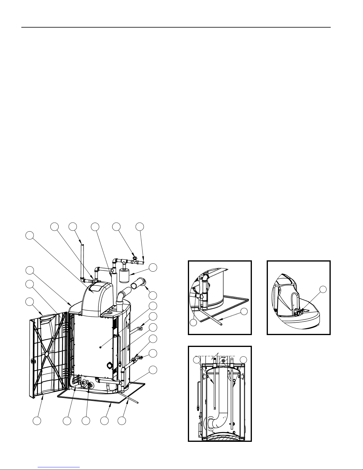
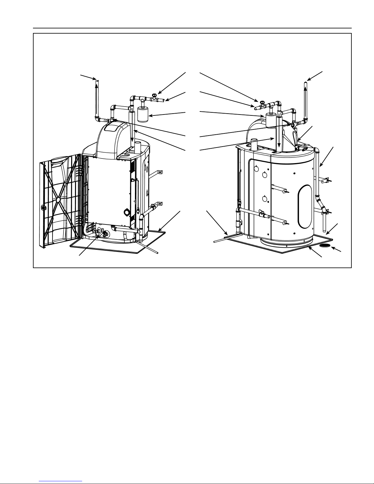
GET TO KNOW YOUR WATER HEATER - GAS MODELS
A Mixing Valve***
B Hot Water Outlet (Tempered)***
C Pipe Insulation***
D Inlet Water Shutoff Valve***
E Cold Water Inlet***
F Expansion Tank***
G Vent Termination Elbow**
H Access Door (Heat Engine)
I Earthquake Strap***
J Power Cord*
K Main Manual Gas Shutoff Valve***
L Gas Supply***
M Sediment Pocket***
N Condensate Tube
O Drain Pan***
P Drain Valve
Q Heat Engine Hose - Cold In
R Casing Door (Plastic)
S Display Enclosure (Plastic)
T Heat Engine Hose - Hot Out
U Side Casing (Plastic)
V Top Casing Enclosure (Plastic)
W Exhaust Elbow Assembly
X T&P Relief Valve
Y Anode
Z Inlet Dip Tube
* CAUTION HARNESS HAS 120 VAC. IN
OPERATION.
** See “Planning the Vent System,” “Installation
of Vent System” and “Condensate” for more
information.
*** These items not included.
A
V
U
T
S
C
EDB
F
X
G
H
I
W
J
K
L
Y
M
N
Z
R
9
O
PQ
N
FIGURE 1

INSTALLATION CONSIDERATIONS
ROUGH IN DIMENSIONS
Dimension shown are in inches [cm]
Top View
Left Side View
FIGURE 2
Capacity, Gas and Electrical Characteristics
Model Approx. Capacity Input Gas
U.S. Gals. Litres BTU/hr Max.
153.331010 25 94.6 100,000 Nat. 14.0 (3.49) 5.0 (1.25) 4.2 (1.05) 120/60 2.5
153.331000 HA 25 94.6 100,000 Nat. 14.0 (3.49) 5.0 (1.25) 4.2 (1.05) 120/60 2.5
Minimum gas supply pressure must be maintained under both load and no load (dynamic and static) conditions.
Manifold Pressure is preset on the gas valve by the manufacturer; DO NOT ATTEMPT TO ADJUST!
Thermal effi ciency is 90%.
If the hardness of your water supply is more than of 12 grains per gallon (200 mg/L), if your water supply is acidic or otherwise impure,
the water supply must be treated with approved methods.
Minimum Clearance To Combustibles Service Clearance
Top Front Vent Back Sides Floor Front Sides
00000021” (53.3 cm) 12” (30.5 cm) 300
This appliance must be installed in accordance with local codes or, in the absence of local codes, the “National Fuel Gas Code” ANSI
Z223.1/NFPA 54.
Not for installation in a Manufactured Home (Mobile Home).
This water heater is suitable for water (potable) heating only.
This water heater is suitable for installation in a closet or alcove.
Type
Gas Supply Pressure Manifold Pressure Electrical Characteristics
in. WC (kPa)
Min.
in. WC (kPa)
in. WC (kPa) Volts/Hz Amperes
Test Pressure
P.S.I.
10

INSTALLATION REQUIREMENTS FOR THE COMMONWEALTH OF MASSACHUSETTS
For all side wall terminated, horizontally vented power vent, gas fueled water heaters installed in every dwelling, building
or structure used in whole or in part for residential purposes, including those owned or operated by the Commonwealth
and where the side wall exhaust vent termination is less than seven (7) feet above finished grade in the area of the
venting, including but not limited to decks and porches, the following requirements shall be satisfied:
INSTALLATION OF CARBON MONOXIDE DETECTORS At the time of installation of the side wall horizontal vented gas fueled
equipment, the installing plumber or gasfi tter shall observe that a hard wired carbon monoxide detector with an alarm and battery back-up
is installed on the fl oor level where the gas equipment is to be installed. In addition, the installing plumber or gasfi tter shall observe that
a battery operated or hard wired carbon monoxide detector with an alarm is installed on each additional level of the dwelling, building
or structure served by the sidewall horizontal vented gas fueled equipment. It shall be the responsibility of the property owner to secure
the services of qualifi ed licensed professionals for the installation of hard wired carbon monoxide detectors.
In the event that the side wall horizontally vented gas fueled equipment is installed in a crawl space or an attic, the hard
wired carbon monoxide detector with alarm and battery back-up may be installed on the next adjacent fl oor level.
In the event that the requirements of this subdivision can not be met at the time of completion of installation, the owner shall
have a period of thirty (30) days to comply with the above requirements provided that during said thirty (30) day period, a
battery operated carbon monoxide detector with an alarm shall be installed.
APPROVED CARBON MONOXIDE DETECTORS Each carbon monoxide detector as required in accordance with the
above provisions shall comply with NFPA 720 and be ANSI/UL 2034 listed and CSA certifi ed.
SIGNAGE A metal or plastic identifi cation plate shall be permanently mounted to the exterior of the building at a minimum
height of eight (8) feet above grade directly in line with the exhaust vent terminal for the horizontally vented gas fueled
heating appliance or equipment. The sign shall read, in print size no less than one-half (1/2) inch in size, “GAS VENT
DIRECTLY BELOW. KEEP CLEAR OF ALL OBSTRUCTIONS.”
INSPECTION The state or local gas inspector of the side wall horizontally vented gas fueled equipment shall not approve
the installation unless, upon inspection, the inspector observes carbon monoxide detectors and signage installed in
accordance with the provisions of 248 CMR 5.08(2)(a) 1 through 4.
EXEMPTIONS: The following equipment is exempt from 248 CMR 5.08(2)(a)1 through 4:
1. The equipment listed in Chapter 10 entitled “Equipment Not Required To Be Vented” in the most current edition of NFPA 54
as adopted by the Board; and
2. Product Approved side wall horizontally vented gas fueled equipment installed in a room or structure separate from the
dwelling, building, or structure used in whole or in part for residential purposes.
MANUFACTURER REQUIREMENTS - GAS EQUIPMENT VENTING SYSTEM PROVIDED When the manufacturer
of Product Approved side wall horizontally vented gas equipment provides a venting system design or venting system
components with the equipment, the instructions provided by the manufacturer for installation of the equipment and the
venting system shall include:
1. Detailed instructions for the installation of the venting system design or the venting system components; and
2. A complete parts list for the venting system design or venting system.
MANUFACTURER REQUIREMENTS - GAS EQUIPMENT VENTING SYSTEM NOT PROVIDED When the manufacturer
of a Product Approved side wall horizontally vented gas fueled equipment does not provide the parts for venting the fl ue
gases, but identifi es “special venting systems,” the following requirements shall be satisfi ed by the manufacturer:
1. The referenced “special venting system” instructions shall be included with the appliance or equipment installation instructions;
and
2. The “special venting systems” shall be Product Approved by the Board, and the instructions for that system shall include
a parts list and detailed installation instructions.
A copy of all installation instructions for all Product Approved side wall horizontally vented gas fueled equipment, all venting
instructions, all parts lists for venting instructions, and/or all venting design instructions shall remain with the appliance or
equipment at the completion of the installation.
11
WATER PIPING - MIXING VALVE USAGE
TEMPERED
POTABLE WATER
SUGGESTED PIPING
ARRANGEMENT
FOR TOP
CONNECTIONS
SHUT-OFF VALVE
COLD WATER
INLET
THERMAL
EXPANSION
TANK
MIXING
VALVE
(OPTIONAL)
PIPE INSULATION
(RECOMMENDED)
TEMPERED
POTABLE WATER
TEMPERATUREPRESSURE
RELIEF VALVE
DISCHARGE
PIPE (DO NOT
CAP OR PLUG)
DRAIN PAN
DRAIN VALVE
FIGURE 3
This appliance has been design certifi ed as complying with
ANSI Z21.10.3/CSA 4.3 (latest revision) for water heaters
and is considered suitable for:
Water (Potable) Heating: All models are considered
suitable for water (potable) heating.
The Hybrid water heater is a unique design that combines
the technology of both the storage tank and tankless type
water heaters. A tankless water heater ensures a fi xed
constant outlet water temperature. This is achieved by
modulating the water fl ow to ensure that this temperature
is maintained. In the Hybrid the water supply is heated
as it fl ows through the heat exchanger over the burners
similar to the tankless water heaters. The heated water is
then stored in the top of the storage tank.
The tank outlet water temperature will be within a maximum
of 5°F (2.8°C) of the display set-point when the unit ends
the call for heat.
If required by local codes or if a higher fi xed temperature
is required, a mixing valve can be installed as shown on
Figure3.
Please note the following:
The system should be installed only with piping that is
suitable for potable (drinkable) water such as copper,
METAL
TO SUITABLE
DRAIN
CPVC, PEX or polybutylene. DO NOT use PVC water
piping.
DO NOT use any pumps, valves, or fi ttings that are not
compatible with potable water.
DO NOT use valves that may cause excessive restriction
to water fl ow. Use full fl ow ball or gate valves only.
DO NOT use any lead based solder in potable water
lines. Use appropriate tin-antimony or other equivalent
material.
DO NOT tamper with the gas control/thermostat, igniter
or temperature and pressure relief valve. Only qualifi ed
service technicians should service these components.
DO NOT use with piping that has been treated with
chromates, boiler seal, or other chemicals.
DO NOT add any chemicals to the system piping which
will contaminate the potable water supply.
HOT WATER CAN SCALD:
Water heaters are intended to produce hot water. Water
heated to a temperature which will satisfy space heating,
clothes washing, dish washing, and other sanitizing needs
can scald and permanently injure you upon contact. Some
people are more likely to be permanently injured by hot
water than others. These include the elderly, children,
and the physically or developmentally disabled. If anyone
6 in.
(15cm)
MAX.
AIR GAP
FLOOR
DRAIN
12

using hot water from this heater fi ts into one of these
groups or if there is a local code or state law requiring a
certain temperature water at the hot water tap, then you
must take special precautions. In addition to using the
lowest possible temperature setting that satisfi es your hot
water needs, a means such as a Mixing Valve should be
used at the hot water taps used by these people or at the
water heater (see Figure 3). Mixing valves are available at
plumbing supply or hardware stores. Consult a Qualifi ed
Installer or Service Agency. Follow the mixing valve
manufacturer’s instructions for installation of the valves.
Before changing the factory setting on the thermostat, read
the “Temperature Regulation” section in this manual.
control of this water heater are polarity sensitive. Ensure
the electrical supply is connected correctly in the receptacle
box. Failure to connect correctly will prevent the unit from
functioning properly.
Installation of the water heater must be accomplished in
such a manner that if the tank or any connections should
leak, the fl ow will not cause damage to the structure. For
this reason, it is not advisable to install the water heater
in an attic or upper fl oor. When such locations cannot be
avoided, a suitable metal drain pan should be installed
under the water heater. Drain pans are available at your
local hardware store. Such a drain pan must have a
clearance of at least 1.0 in. (2.5cm) greater than any point
on the water heater’s outer jacket and must be piped to
an adequate drain. The pan must not restrict combustion
air fl ow. See Figure 1.
FACTS TO CONSIDER ABOUT LOCATION
Carefully choose an indoor location for the new water
heater, because the placement is a very important
consideration for the safety of the occupants in the building
and for the most economical use of the appliance. This
water heater is not for use in manufactured (mobile)
homes or outdoor installation.
Whether replacing an old water heater or putting the water
heater in a new location, the following critical points must
be observed:
Select a location indoors as close as practical to the
1.
vent terminal or location to which the water heater vent
piping is going to be connected, and as centralized
with the water piping system as possible.
A pressure-reducing valve and/or an expansion tank
2.
may be required for installations where the water
pressure is high. The pressure-reducing valve should
be located on the supply to the entire house in order
to maintain equal hot and cold water pressure.
Selected location must provide adequate clearances
3.
for servicing and proper operation of the water
heater.
Avoid locations that could cause the water heater to
4.
freeze from outside air.
Selected location must provide access to a properly
5.
grounded electrical branch circuit. A dedicated circuit
is preferred. Do not use a GFI outlet.
Important: Do not use an extension cord to connect the
water heater to an electrical outlet.
Important: The electrical controls used inside the gas
Water heater life depends upon water quality, water
pressure and the environment in which the water heater
is installed. Water heaters are sometimes installed in
locations where leakage may result in property damage,
even with the use of a drain pan piped to a drain. However,
unanticipated damage can be reduced or prevented by a
leak detector or water shut-off device used in conjunction
with a piped drain pan. These devices are highly
recommended and are available from some plumbing
supply wholesalers and retailers, and detect and react to
leakage in various ways:
• Sensors mounted in the drain pan that trigger an alarm
or turn off the incoming water to the water heater when
leakage is detected.
• Sensors mounted in the drain pan that turn off the water
supply to the entire building when water is detected in
the drain pan.
• Water supply shut-off devices that activate based on
the water pressure differential between the cold water
and hot water pipes connected to the water heater.
• Devices that will turn off the gas supply to a gas water
heater while at the same time shutting off its water
supply.
A VOID AREAS WHERE FLAMMABLE LIQUIDS (V APORS)
ARE LIKEL Y TO BE PRESENT OR ST ORED (GARAGES,
STORAGE AND UTILITY AREAS, ETC.): Flammable
liquids (such as gasoline, solvents, propane (LP or butane,
etc.) and other substances (such as adhesives, etc.)) emit
fl ammable vapors which can be ignited by a gas water
heater’s igniter or main burner. The resulting fl ashback
and fi re can cause death or serious burns to anyone in
the area.
Also, the water heater must be located and/or protected so
13
it is not subject to physical damage by a moving vehicle.
DANGER
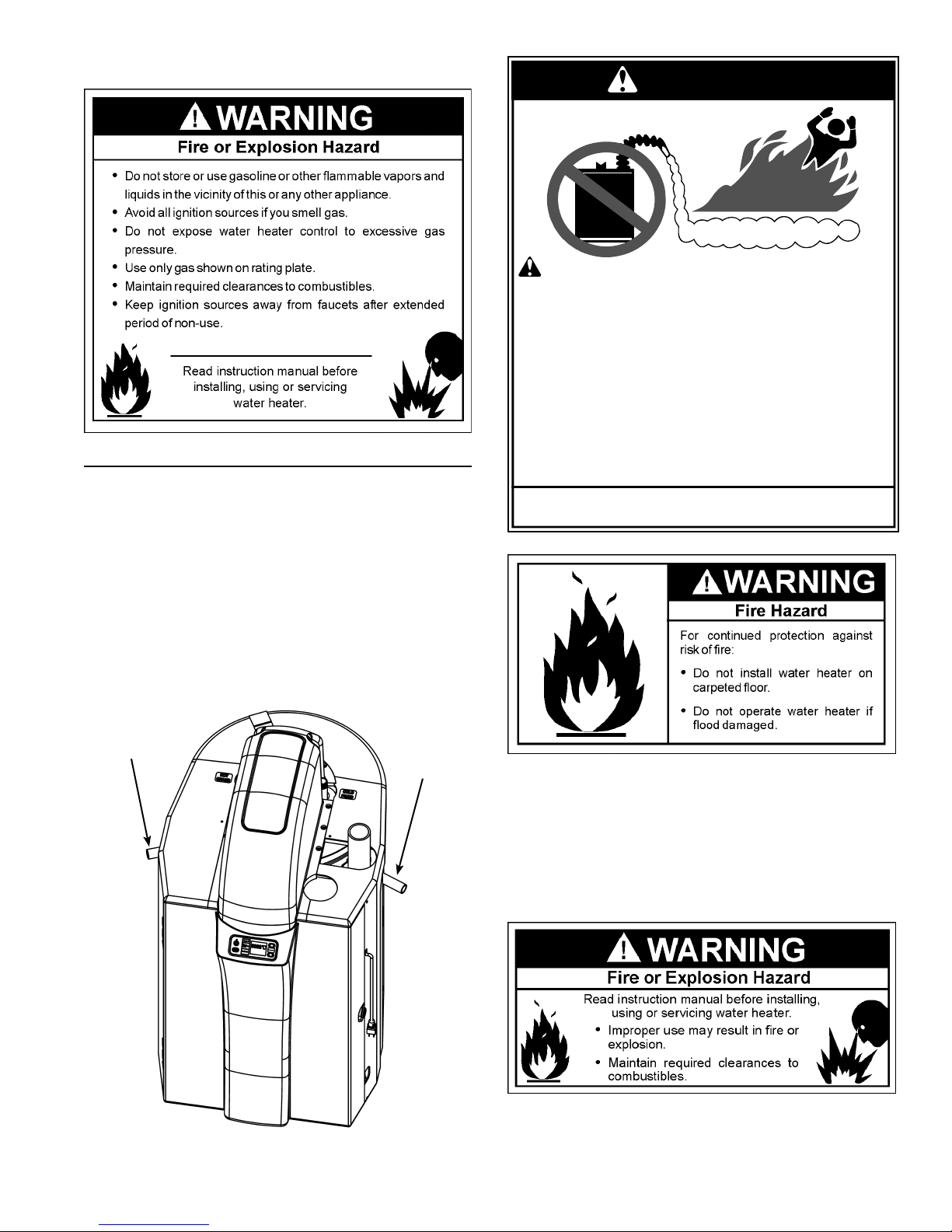
HANDLE INSTALLATION
For ease of handling and carrying, plugs are provided
in the side of the shroud that can be removed and pipe
handles inserted (see Figure 4).
• Remove plastic plugs from shroud side panels.
• Screw a short length of 3/4” NPT pipe into the sides of
the water heater.
• Use the handles to move the water heater to the desired
location.
• Remove the handles.
• Reinstall the plastic plugs in the shroud side panels.
FLAMMBLE
Vapors from flammable
liquids may explode and
catch fire causing death or
severe burns.
Do not use or store
flammable products such as
gasoline, solvents or adhesives in the same room or
area near the water heater.
Keep flammable products:
1. far away from heater,
2. in approved containers,
3. tightly closed and
4. out of children's reach.
Installation: Do not install the water heater where flammable
products will be stored or used.
Flammable Vapors
Water heater has a main
burner and spark generator.
The spark generator:
1. can be triggered at any
time and
2. the spark will ignite
flammable vapors.
Vapors:
1. cannot be seen,
2. are heavier than air,
3. go a long way on the floor
and
4. can be carried from other
rooms to the the
electodes by air currents.
Handle
FIGURE 4
14
Handle
This water heater must not be installed directly on
carpeting. Carpeting must be protected by metal or wood
panel beneath the appliance extending beyond the full
width and depth of the appliance by at least 3in. (7.6cm)
in any direction, or if the appliance is installed in an alcove
or closet, the entire fl oor must be covered by the panel.
Failure to heed this warning may result in a fi re hazard.
When installing the heater, consideration must be given to
proper location. Location selected should be as close to
the wall as practicable and as centralized with the water
piping system as possible.
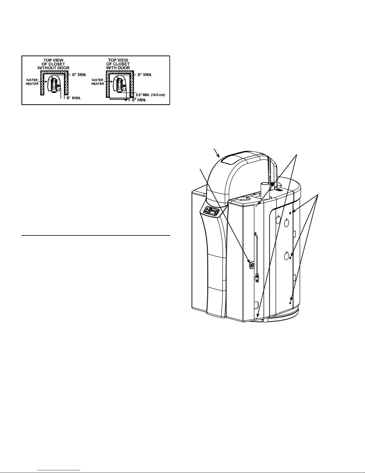
FIGURE 5
Minimum clearances between the water heater and
combustible construction are 0 in. at the sides and rear,
0 in. (0cm) from the front and 2 in. (5.08cm) from the top
(see Figure 5). If clearances stated on the heater differ
from these distances, install water heater according to
clearances stated on the heater.
Adequate top clearance of 24 in. (61cm) for servicing this
appliance, such as changing the anodes etc., should be
considered before installation.
Remove the right side panel
Use a screwdriver to remove the screw from the
1.
bottom, front of the right side panel.
Remove the three screws from the right side panel
2.
towards the rear of the unit.
Remove the screw from the top of the unit.
3.
Push the panel back and lift out.
4.
Remove the left side panel
Use a screwdriver to remove the screw from the
1.
bottom, front of the left side panel.
Remove the three screws from the left side panel
2.
towards the rear of the unit.
Remove the screw from the top of the unit.
3.
Push the panel back and lift out.
4.
Top Casing
(Front)
Access To
Door Pins
Door
Lock
Screws
A minimum front clearance of 20 in. (51cm) and 10 in.
(26cm) of side clearance must be allowed for access to
replaceable parts.
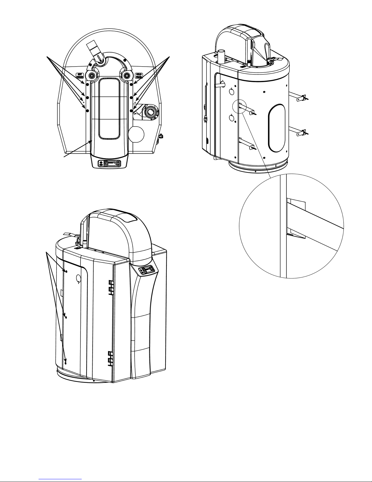
EARTHQUAKE ZONES
In Earthquake Zones the water heater must be braced,
anchored, or strapped to avoid moving during an
earthquake. Contact local utilities for code requirements
in your area. Follow the manufacturer’s instructions for
installing the braces. Be sure to wear protective goggles
and gloves when handling any kind of sheet metal
product.
Tabs have been provided on each side of the rear portion
of the shroud. The top and bottom of each tab must be
cut and gently bent “inwards” thus allowing the straps to
exit the shroud (see Figure 9).
In order to access the tabs and install the earthquake
straps it is necessary to remove the top, front and side
panels of the shroud as follows (see Figures 6 - 8):
Door opening
Unlock the door by rotating the lock counter-clockwise
1.
with a wide, slot screwdriver.
Release the top and bottom door pins by prying the
2.
pins out, using a small screwdriver.
Open the door (the door remains fastened to the left
3.
side panel).
FIGURE 6
Remove the top casing (front).
Use a screwdriver to remove the six screws securing
1.
the top casing.
Lift up and remove casing top (front).
2.
15
Screws Screws
Top
Casing (Front)
FIGURE 7
Screws
FIGURE 9
After the heater has been positioned and the earthquake
straps have been installed, re-assemble the shroud in the
reverse order.
FIGURE 8
16
COMBUSTION AIR AND VENTILATION
A gas water heater cannot operate properly without the
correct amount of air for combustion. Do not install in a
confi ned area such as a closet, unless you provide air as
shown in the “Facts to Consider About Location” section.
Never obstruct the fl ow of ventilation air. If you have any
doubts or questions at all, call your gas supplier. Failure to
provide the proper amount of combustion air can result in
a fi re or explosion and cause death, serious bodily injury,
or property damage.
FIGURE 10
In unconfi ned spaces in buildings, infi ltration may be
adequate to provide air for combustion, ventilation and
dilution of flue gases. However, in buildings of tight
construction (for example, weather stripping, heavily
insulated, caulked, vapor barrier, etc.), additional air may
need to be provided using the methods described in
“Appliances in Confi ned Space” that follows.”
APPLIANCES IN CONFINED SPACES
CONFINED SPACE is a space whose volume is less
than 50 cubic feet per 1,000 Btu per hour (4.8m3 per kW)
of the aggregate input rating of all appliances installed in
that space.
When drawing combustion air from inside a building to a
confi ned space, such a space should be provided with two
permanent openings. ONE WITHIN 12 in. (30cm) OF THE
ENCLOSURE TOP AND ONE WITHIN 12 in. (30cm) OF
THE ENCLOSURE BOTTOM. Each opening should have
a free area of 1 square inch per 1000 Btu/hr (22 cm2/kW)
of the total input of all appliances in the enclosure, but not
less than 100 square in. (645 cm2).
If the confi ned space is within a building, air for combustion
and ventilation must be obtained from outdoors. When
directly communicating with the outdoors or communicating
through vertical ducts, two permanent openings, located
in the above manner, should be provided. Each opening
should have a free area of not less than 1 square inch per
4000 Btu/hr (5.5 cm2/kW) of total input of all appliances in
the enclosure. If horizontal ducts are used, each opening
should have a free area of not less than 1 square inch per
2000 Btu/hr (1 1 cm2/kW) of the total input of all appliances
in the enclosure.
If this water heater will be used in beauty shops, barber
shops, cleaning establishments, or self-service laundries
with dry cleaning equipment, it is imperative that the water
heater(s) be installed so that all air for combustion and
ventilation is taken from outdoors.
Note: Vent length should be long enough that the outside
air will not freeze the water heater.
Propellants of aerosol sprays and volatile compounds,
(cleaners, chlorine based chemicals, refrigerants, etc.) in
addition to being highly fl ammable in many cases, will also
react to form corrosive hydrochloric acid when exposed to
the combustion products of the water heater. The results
can be hazardous, and also cause product failure.
APPLIANCES IN UNCONFINED SPACES
UNCONFINED SP ACE is space whose volume is not less
than 50 cubic feet per 1,000 Btu per hour (4.8 cubic meters
per kW) of the aggregate input rating of all appliances
installed in that space. Rooms communicating directly with
the space in which the appliances are installed, through
openings not furnished with doors, are considered a part
of the unconfi ned space.
A. ALL AIR FROM INSIDE BUILDINGS: (See Figures 10
& 11)
The confi ned space should be provided with two permanent
openings communicating directly with an additional
room(s) of suffi cient volume so that the combined volume
of all spaces meets the criteria for an unconfi ned space.
The total input of all gas utilization equipment installed in
the combined space should be considered in making this
determination. Each opening should have a minimum free
area of 1 square inch per 1,000 Btu per hour (22 cm2/kW)
of the total input rating of all gas utilization equipment in
the confi ned space, but not less than 100 square in. (645
cm2). One opening should commence within 12 in. (30cm)
of the top and one commencing within 12 in. (30cm) of the
bottom of the enclosures.
17

FIGURE 11
B. ALL AIR FROM OUTDOORS: (See Figures 12, 13 and
14)
The confi ned space should be provided with two permanent
openings, one commencing within 12 in. (30cm) of the top
and one commencing within 12 in. (30cm) from the bottom
of the enclosure. The openings should communicate
directly , or by ducts, with the outdoors or spaces (crawl or
attic) that freely communicate with the outdoors.
1. When directly communicating with the outdoors, each
opening should have a minimum free area of 1 square
inch per 4,000 Btu per hour (5.5 cm2/kW) of total input
rating of all equipment in the enclosure (see Figure
12).
FIGURE 12
FIGURE 13
4. When ducts are used, they should be of the same
cross-sectional area as the free area of the openings to
which they connect. The minimum short side dimension
of rectangular air ducts should not be less than 3 in.
(7.6cm) (see Figure 14).
FIGURE 14
5. Alternatively a single permanent opening may be used
when communicating directly with the outdoors, or with
spaces that freely communicate with the outdoors. The
opening should have a minimum free area of 1 square
inch per 3,000 BTU per hour (7.3 cm2/kW) of total input
rating of all equipment in enclosure (see Figure 15).
2. When communicating with the outdoors through vertical
ducts, each opening should have a minimum free area
of 1 square inch per 4,000 Btu per hour (5.5 cm2/kW)
of total input rating of all equipment in the enclosure
(see Figure 13).
3. When communicating with the outdoors through
horizontal ducts, each opening should have a minimum
free area of 1 square inch per 2,000 Btu per hour (11
cm2/kW)) of total input rating of all equipment in the
enclosure (see Figure 14).
18
FIGURE 15
 Loading...