

Page 1
Use & Care Guide
Manual de Usa y Cuidado
English / Espafiol
more Elite°
@ @
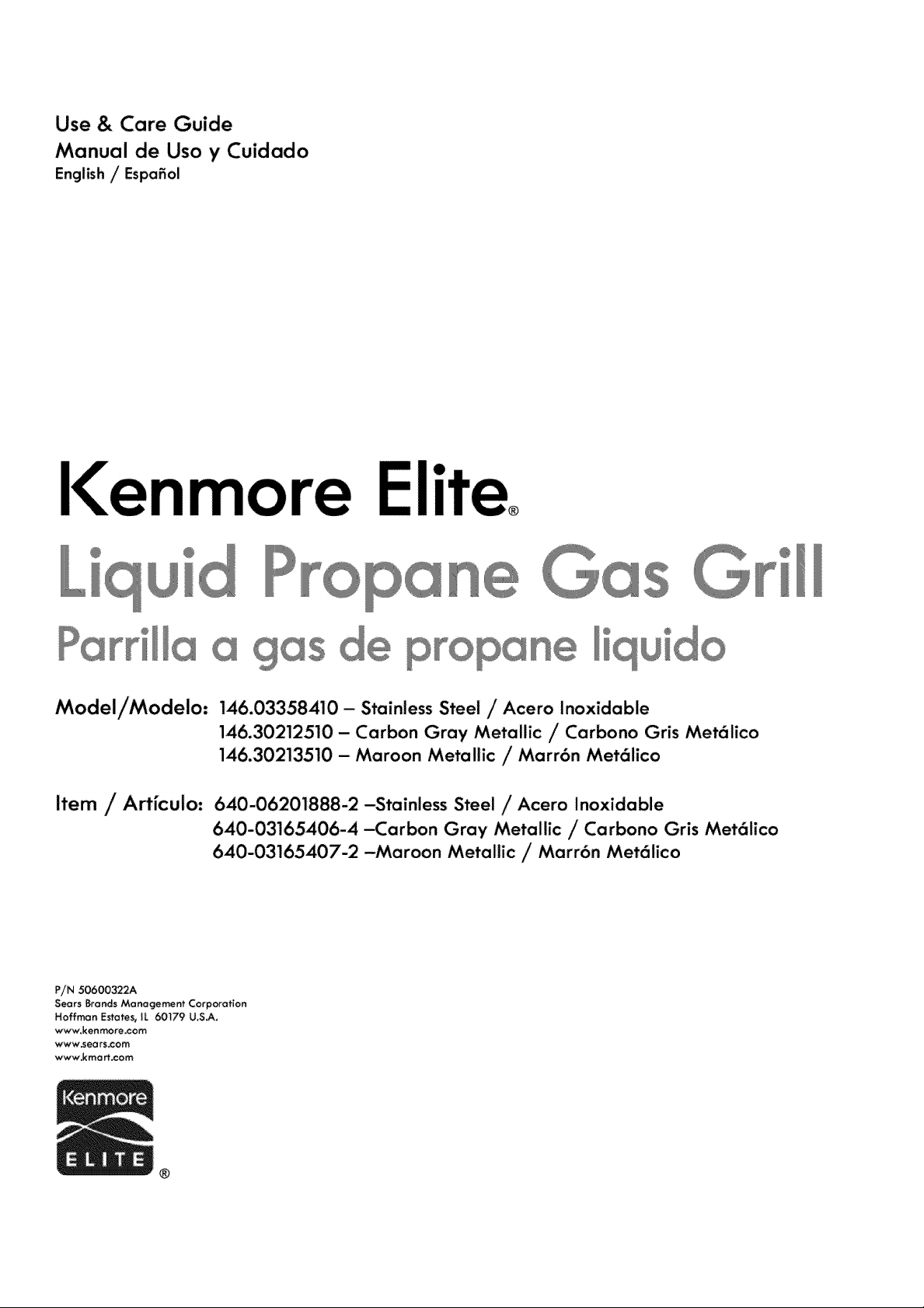
Model/Modelo: 146.03358410 - Stainless Steel / Acero Inoxidable
146.30212510 - Carbon Gray Metallic / Carbono Gris Met61ico
146.30213510 - Maroon Metallic / Marr6n Met61ico
Item / Art[cuio: 640-06201888-2-Stainless Steel/Acero Inoxidable
640-03165406-4-Carbon Gray Metallic /Carbono Gris Met61ico
640-03165407-2 -Maroon Metallic / Marr6n Met61ico
P//N 50600322A
Sears Brands Management Corporation
Hoffrr_n Estates, IL 60179 U.S_,
www, ken more.cam
www=sea rs.com
www,kmart.cem
@
®
Page 2
Dear New Kenmore Owner,
Congratulations on the purchase your new Kenmore Elite 700 Series Gas Grill! Kenmore Elite
Series Grills have been designed and engineered from the bottom up, with focus on even the
smallest detail. This grill has been designed to provide you with even cooking results, fast
performance, and precise control so you have complete confidence every time you grill.
The Kenmore brand has over a 100-year history of providing innovative solutions that enable our
members and customers to get more out of their lives. During this time, the Kenmore brand has
evolved through technology, style and the specific needs of every generation. Yet, one constant
remains - all Kenmore products offer keys to more living such as greater convenience, better
performance and time saved. Your new Kenmore Elite gas grill is another example of this great
Kenmore legacy.
Of course, if you should have any issues with your new grill, please contact us at 1-800-4-MY-
HOME, or through Sears.com. We also hope you will share your grill recipes and stories with us
and others. You can do this by visiting the Kenmore cookmore.com or grillingishappiness.com
Thank you for allowing us to make this amazing product a part of your life. We hope you enjoy
many great meals with your family and friends creating many happy memories.
Ifyou smell gas
_, Shuf off gas te the eppliance.
2, Extinguish _y open flame,
3, Open lid,
4, ff odo_ cont_nues_ keep away ftorn the
appliance a_d _mmedi_te_y call your ga_
supp[ie_ Or you_ fi_÷ depe_ment,
2 ° 146,03358410
2014 © Sears Brands, LLC
Kenmore.•
Do _ot store or u_e g_$o|tne or cthe_
f_ammGble [iquids o_ vu_ in the vicinity of
thi_ or _ny ellhe_ appIionce,
2. An LP cylinder not connected _Or use _ha[_ not
s_ored in _5e v_¢_n_ty O_ this or any o_her
oppiiance,
tested for living
Page 3
Call Grill Service Center For Help And Parts
If you have questions or need assistance during assembly,
please call 1-888-287-0735. You will be speaking to a
representative of the grill anufacturer and not a Sears
employee. To order new parts call Sears at
Product Record
IMPORTANT:Fill out the product record informationbelow.
Model Number
Serial Number
See rating label on grill for serial number.
Date Purchased
Installation Safety Precautions
* Please read this User's Manual in its entirety before using
the grill.
* Failure to follow the provided instruction can result in
seriously bodily injury and/or property damage.
° Some parts of this grill may have sharp edges. Please
wear suitable protective gloves.
* Use grill, as purchased, only with LP (propane) gas and the
regulator/valve assembly supplied.
o Grill installation must conform with local codes, or in their
absence of local codes, with either the National Fuel Gas
Code, ANSI Z223.1/NFPA 54, Natural Gas and Propane
Installation Code, CSA B149.1, or Propane Storage and
Handling Code, B149.2, or the Standard for Recreational
Vehicles, ANSI A 119.2/'NFPA 1192, and CSA Z240 RV
Series, Recreational Vehicle Code, as applicable.
° All electrical accessories (such as rotisserie) must be
electrically grounded in accordance with local codes, or
National Electrical Code, ANSI / NFPA 70 or Canadian
Electrical Code, CSA C22.1. Keep any electrical cords
and/or fuel supply hoses away from any hot surfaces.
° This grill is safety certified for use in the United States
and/or Canada only. Do not modify, for use in any other
location. Modification will result in a safety hazard.
For residential use only. Do not use for commercial
cooking,
IMPORTANT: This grill is intended for outdoor use only and is
not intended to be installed in or on recreational vehicles or
boats.
NOTE TO INSTALLER:Leave this User'sManual with the
customer after delivery and/or installation.
NOTE TO CONSUMER: Leave this User's Manual in a
convenient place for future reference.
Safety Symbols
The symbols and boxes shown below explain what each heading
means. Read and follow all of the messages found throughout
the manual,
DANGER: Indicates an imminently hazardous situation
which, if not avoided, wilUresult in death or serious injury.
WARNING: indicates an potentially hazardous situation
which, if not avoided, cound result in death or serious iniury.
CAUTION: Indicates a potentially hazardous situation or
unsafe practice which, if not avoided, may result in minor or
moderate injury.
146.O3358410 - 3
Page 4
For Your Safety ..,
Grill Service Center, _,
Product Record Information ..,
Installation Safety Precautions...
Safety Symbols ,_.
Kenmore Grill Warranty,,,
Use and Care...
Parts List,.,
Parts Diagram .,.
Before Assembly,,.
Assembly..,
Troubleshooting ,.,
Repair Protection Agreements
Congratulations on making a smart purchase. 'four new Kenmord "_
product is designed and manufactured for years of dependable
operation. But like all products, it may require repair from time to time
That's when having a Repair Protection Agreement can save you
money and aggravation,
Purchuse u Repair Protechbn Agreement now and pro/ecf yours'elf
/,tom unexpec/ed hoss/e onci expense.
Here's what the Repair Protection Agreement _ includes:
2
3
3
3
3
5
. .. 6-14
...15
. .17
. .. 18-20
., .21-38
., .39-41
Sears Installation Service
For Sears professional installation of home appliances, garage
door openers, water heaters, and other major home items, in
the U.S.A cal! 1-800-4-MY-HOME ®
CALIFORNIA PROPOSITION 65
1. Combustion by-products produced when using this
product contain chemicals known to the State of
California to cause cancer, birth defects, and other
reproductive harm.
2. This Product contains chemicals, including lead and
lead compounds, known to the State of California to
cause cancer, birth defects or other reproductive
harm.
Wash your hands after usina this product.
This grill is rated at 96,000 BTU. This is more than one
standard 20 lb. LP tank can deliver at once, especially
in cold weather. Do not operate the 5 main burners
while the rotisserie burner is being used. Or do not
operate the rotisserie burner when the 5 main burners
are being used.
Expertservice by our 10,000professionalrepairspecialists
Unlimitedservice and nocharge for partsand labor on all
covered repairs
Productreplacementupto $1500if your covered product
can't befixed
Discountof 25% from regular price of service and related
installedpartsnotcovered by the agreement;also,25°,/0off
regular price of preventivemaintenancecheck
Fasthelpby phone - we call it RapidResolution
phonesuppo4 froma Searsrepresentative Thinkof us
asa "talking owner'smanual."
Once you purchase the Repair Protection Agreement, a simple phone
call isall that it takes for you to schedule service. You can call
anytime day or night, or schedule a service appointment online.
TheRepairProtectionAgreementisa dskJree purchase,If you
cancel for any reasonduringthe product warranty period,we will
providea fullrefund,Or;,a prorated refundanytimeafter the
product warranty period expires.Purchaseyour Repair
ProtectionAgreementtoday!
Somelimitationsandexclusionsapply. Forprices and
additional informationintheU.S.A.call 1-800-827-6655.
4 ° 146.O3358410
Page 5
KENMORE ELITE LIMITED WARRANTY
WITH PROOF OF SALE, the following warranty coverage applies when this appliance is correctly installed, operated
and maintained according to all supplied instructions_To arrange for in-home warranty service,
call I_800-4_MY_HOME® (1_800_46%4663)
FOR TWO YEARS from the date of sale this appliance is warranted against defects in material or workmanship. A
defective appliance will receive free repair or replacement at option of seller.
For the time periods from the sale date UistedbeUo,_,the named part will be repUaced free of charge if it rusts through or
burns througk After the second year from the sanedate you are responsible for the labor cost of
part instaJRation.
TWO YEARS- Heat Diffusers
THREEYEARS- Cooking Grates
FIFTEENYEARS- Burners
TWENTYoFIVE YEARS- Firebox Cast Aluminum Sidewalls or Lid Porcelain Coated Shroud
AnJwarranty coverage excludes ignitor batteries and grill part paint noss,discoloration or surface rusting, which are either
expendable par_sthat can wear out from normaUuse within the warranty period, or are conditions that can be the result
of normal use,accident or improper maintenance_
AHwarranty coverage applies is void if this appliance is ever used for other than private household purposes_
This warranty covers ONLY defects in material and workmanship_ and will NOT pay for:
1_ ExpendabUeitems that can wear out from normal use within the warranty period including but not limited to
batteries, screw-in base light bulbs and surface coatings or finishes.
2. A service technician to dean or maintain thisappliance, or to instruct the user in correct appniance installation,
operation and maintenance.
3. Service calls to correct appliance installation not performed by Sears authorized service agents, or to repair
problems with house fuses, circuit breakers, house wiring, and pDmbing or gas supply systems resulting from such
instalJation_
4. Damage to or failure of this appliance resulting from installation not performed by Sears authorized service agents,
including installation that was not inaccord with electrical, gas or plumbing codes.
5. Damage to or failure of this appliance, including discoloration or surface rust,if it is not correctly operated and
maintained according to all supplied instructions
& Damage to or failure of this appNiance, including discdoration or surface rust,resuatingfrom accident, alteration,
abuse, misuse or usefor other than its intended purpose.
7. Damage to or failure of this appliance, including discdoration or surface rust,caused by the use of detergents,
cleaners, chemicals or utensils other than those recommended in all instructions supplied with the product.
8_ Damage to or failure of this appliance resulting from natural or other catastrophe, such as flood, fire or storm.
9. Damage to or failure of parts or systems resulting from unauthorized modifications made to this appliance.
10_ Service to an appliance if the model and serial plate is missing, altered, or cannot easily be determined to have the
appropriate certification logo.
Disclaimer of implied warranties; limitation of remedies
CustomePs sole and exclusive remedy under this limited warranty shall be product repair or replacement as provided
herein. Implied warranties, including warranties of merchantability or fitness for a particular purpose, are limited to two
years on the appliance, five years on heat diffusers, fifteen years on burner% and twenty_five years on sidewalls, lid
shroud and grates, or the shortest period allowed by Jaw. Seller shall not be liable for incidental or consequential
damages_ Some states and provinces do not allow the exclusion or limitation of incidental or consequential damages, or
limitation on the duration of implied warranties of merchantability or fitness, so these exclusions or limitations may not
apply to you_
Thiswarranty applies only while this appliance is used in the United States.
Thiswarranty gives you specific legal rights, and you may also have other rights which vary from state to state_
Sears Brands Management Corporation, Hoffman Estates, IL 60179
146.033-58410 ° 5
Page 6
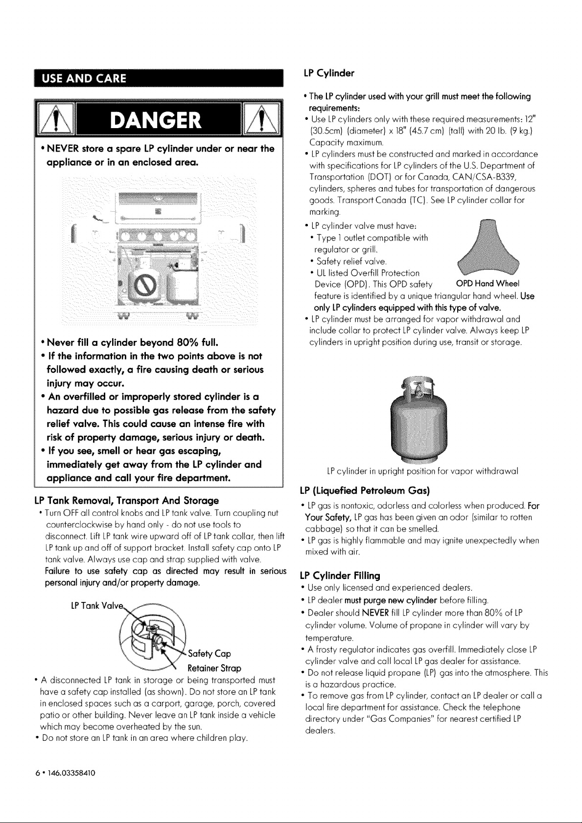
• NEVER store a spare LP cylinder under or near the
appliance or in an enclosed area.
• Never fill a cylinder beyond 80% full.
• If the information in the P,€opoints above isnot
followed exactly, a fire causing death or serious
injury may occur.
• An overfilled or improperly stored cylinder isa
hazard due to possible gas release from the safety
relief valve. This could cause an intense fire with
risk of property damage, serious injury or death.
• If you see, smell or hear gas escaping,
immediately get away from the LP cylinder and
appliance and call your fire department.
LP Tank Removal, Transport And Storage
• Turn OFF all control knobs and LPtank valve. Turn coupling nut
counterclockwise by hand only_ do not use tools to
disconnect. Lift LPtank wire upward off of LPtank collar, then lift
LPtank up and off of support brackeL Install safety cap onto LP
tank valve_ Always use cap and strap supplied with valve_
Failure to use safety cap as directed may result in serious
personal injuryand/or property damage.
LPTankValv__i.i
_", rRetainer Strap
• A disconnected LP tank in storage or being transported must
have a safety cap installed (as shown) Do not store an LPtank
in enclosed spaces such as a carport, garage, porch, covered
patio or other building. Never leave an LPtank inside a vehicle
which may become overheated by the sun.
• Do not store an LPtank in an area where children play.
Safety Cap
LPCylinder
° The LPcylinder used with your grill must meet the following
requirements:
° Use LPcylinders only with these required measurements: 12"
(30.5cm) (diameter) x 18" (45.7 cm) (tall) with 20 lb. (9 kg.)
Capacity maximum.
• LPcylinders must be constructed and marked in accordance
with specifications for LPcylinders of the US_ Department of
Transportation (DOT) or for Canada, CANiCSA-B339,
cylinders, spheres and tubes for transportation of dangerous
goods. Transport Canada (TC). See LPcylinder collar for
marking.
• LPcylinder valve must have:
° Type 1outlet compatible with
regulator or grill
• Safety relief valve.
• UL listed Overfill Protection
Device (OPD)_ This OPD safety OPDHand Wheel
feature is identified by a unique triangular hand wheel Use
only LPcylinders equipped with this type of valve.
• LPcylinder must be arranged for vapor withdrawal and
include collar to protect LPcylinder valve. Always keep LP
cylinders inupright position during use, transit or storage.
LPcylinder in upright position for vapor withdrawal
LP(Liquefied Petroleum Gas)
• LPgasisnontoxic,odorlessand colorlesswhen produced. For
Your Safety, LPgashasbeengiven an odor (similarto rotten
cabbage) sothat it can be smelled.
• LPgas is highlyflammableand mayigniteunexpectedly when
mixedwith air
LPCylinder Filling
• Useonly licensedand experienced dealers.
• LPdealer mustpurge new cyfinder beforefilling.
• Dealer shouldNEVERfiJ!LPcylinder morethan 80% of LP
cylinder vdume_Volumeof propane incylinder wil! vary by
temperature.
• A frosty regulator indicatesgas overfill.Immediatelyclose LP
cylinder valveand call local LPgasdealer for assistance_
" Do notreleaseliquid propane (LP)gasintothe atmosphere_This
isa hazardouspractice.
• To removegas from LPcylinder, contactan LPdealer or call a
local firedepartment for assistance_Checkthetelephone
directory under "'GasCompanies'' for nearestcertified LP
dealers_
6 ° 146.03358410
Page 7
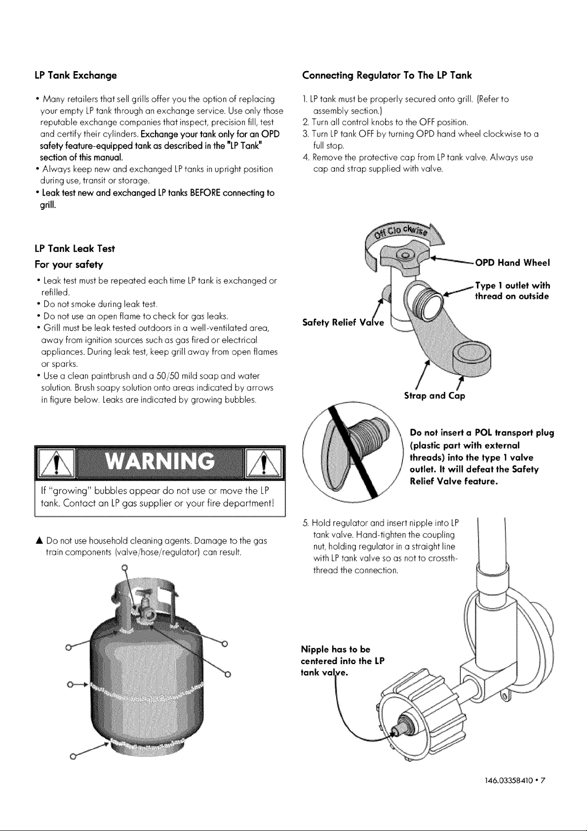
LPTank Exchange Connecting Regulator To The LP Tank
• Many retailersthat sellgrills offer you theoption of replacing
yourempty LPtankthroughan exchangeservice Useonly those
reputableexchange companiesthat inspect,precisionfill,test
andcertify their cylinders Exchangeyour tankonlyfor anOPD
safety feature-equipped tank as described in the "LPTank"
sectionof thismanuaL.
• Always keep new and exchangedLPtanksinupright position
duringuse,transitor storage
• Leaktest newand exchangedLPtanksBEFOREconnecting to
grill.
LP Tank Leak Test
For your safety
* Leak test must be repeated each time LPtank is exchanged or
refilled
" Do not smoke during leak test.
° Do not use an open flame to check for gas leaks.
. Grill must be leak tested outdoors in a well-ventilated area,
away from ignition sources such as gas fired or electrical
appliances During leak test, keep grill away from open flames
or sparks
° Use a clean paintbrush and a 50/50 mild soap and water
solution. Brush soapy solution onto areas indicated by arrows
in figure below Leaks are indicated by growing bubbbs_
1 LPtank must be properly secured onto grill. (Refer to
assembly section}
2 Turn all control knobs to the OFF position
3. Turn LPtank OFF by turning OPD hand wheel clockwise to a
fuji stop
4. Remove the protective cap from LPtank valve. Always use
cap and strap supplied with valve
OPD Hand Wheel
vpe I outlet with
thread on outside
Safety
Strap and Cap
If "growing" bubbles appear do not useor move the LP
tank, Contact an LPgas supplier or your fire department!
A Do notusehouseholdcleaningagents Damageto the gas
train components(valve!hose/regulator) can result
Do not insert a POL transport plug
(plastic part with external
threads) into the type 1 valve
outlet, it will defeat the Safety
Relief Valve feature.
5 Hold regulator and insert nipple into LP
tank valve Hand4ighten the coupling
nut,holding regulator in a straight line
with LPtank valve so as not to crossth-
thread the connection
Nipple has to be
centered into the LP
tank val ye.
146.03358410 ° 7
Page 8
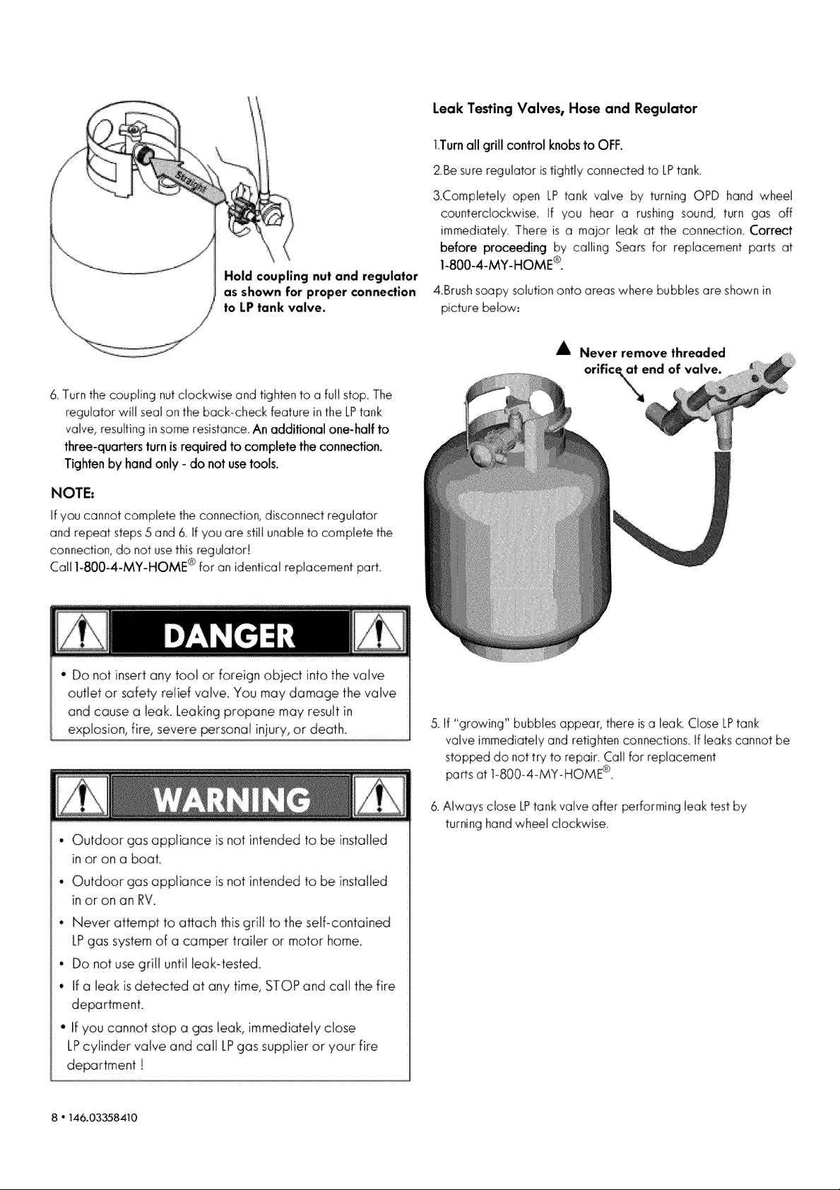
Hold coupling nut and regulator
as shown for proper connection
to LP tank valve.
Leak Testing Valves, Hose and Regulator
1Turnall grill control knobsto OFF.
2Be sure regulator istightly connected to LPtank
3Completely open LP tank valve by turning OPD hand wheel
counterclockwise. If you hear a rushing sound, turn gas off
immediateiy. There is a major leak at the connection. Correct
before proceeding by calling Sears for replacement parts at
1-800-4-MY-HOME ®.
4.Brush soapy solution onto areas where bubbles are shown in
picture below.,
A Never remove threaded
& Turn the coupling nut clockwise and tighten to a full stop. The
regulator will seal on the bacbcheck feature in the LPtank
valve, resulting in some resistance. An additional one-half to
three-quarters turn is required to complete the connection.
Tighten by hand only - do not use toots.
NOTE:
Ifyou cannot complete the connection,disconnect regulator
and repeat steps5 and 6. Ifyou are stillunableto complete the
connection,do not usethisregulator!
Call 1-800-4-MY-HOME® for anidentical replacementpart,
• Do not insert any tool or foreign object into the valve
outlet or safety relief valve, You may damage the valve
and cause a leak. Leakingpropane may result in
explosion, fire, severe personal injury, or death.
orifice\a_end of valve.
5. tf "growing" bubbles appear, there is a leak. Close LPtank
valve immediately and retighten connections, if leaks cannot be
stopped do not try to repair. Call for replacement
parts at 1-800-4-MY-HOME ®
, Outdoor gas appliance is not intended to be installed
in or on a boat.
• Outdoor gas appliance is not intended to be installed
in or on an RV.
• Never attempt to attach this grill to the serf-contained
LPgas system of a camper trailer or motor home.
• Do not use grill until bak-tested.
• if a leak isdetected at any time, STOPand cainthe fire
department.
• if you cannot stop a gas leak, immediately close
LPcylinder valve and call LPgas supplier or your fire
department !
8 " T46.03_8410
& Always close LPtank valve after performing leak test by
turning hand wheel clockwise.
Page 9
For Safe Use of Your Grill and to Avoid Serious
Injury:
• Do not let children operate or play near grill.
° Keep grill area clear and free from materials that
burn.
° Do not block holes in sides or back of grill.
° Use grill only in well-ventilated space. NEVER use
in enclosed space such as carport, garage, porch,
covered patio, or under an overhead structure of
any kind.
° Do not use charcoal or ceramic briquets in a gas
grill.
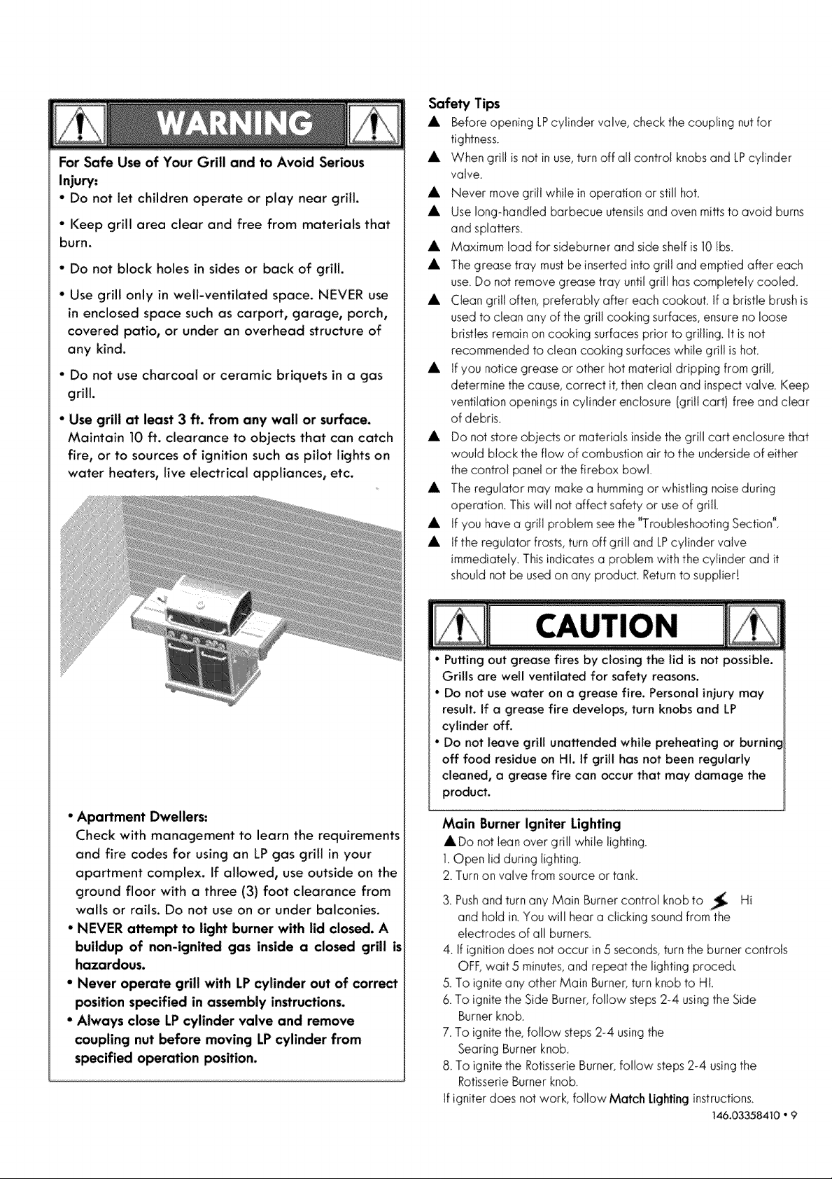
" Use grill at least 3 ft. from any wall or surface.
Maintain 10 ft. clearance to objects that can catch
fire, or to sources of ignition such as pilot lights on
water heaters, live electrical appliances, etc.
Safety Tips
,A, Before opening LPcylinder yah,e, check the coupling nut for
tightness.
A When grill is not in use,turn off all control knobs and LPcylinder
valve.
A Never move grill while in operation or still hot.
A Use long-handled barbecue utensils and oven mitts to avoid burns
and splatters.
A Maximum toad for sideburner and side shelf is 10 Ibs.
A The grease fray must be inserted into grill and emptied after each
use. Do not remove grease tray until grill has completely cooled.
A Clean grill often, preferably after each cookout, tf a bristle brush is
used to clean any of the grill cooking surfaces, ensure no loose
bristles remain on cooking surfaces prior to grilling. It is not
recommended to clean cooking surfaces while gri01is hot.
A If you notice grease or other hot material dripping from grill,
determine the cause, correct it, then clean and inspect valve. Keep
ventilation openings in cylinder enclosure (grill cartl free and clear
of debris.
A Do not store objects or materials inside the grill cart enclosure that
would block the flow of combustion air to the underside of either
the control panel or the firebox bowl.
A The regulator may make a humming or whistling noise during
operation. This will not affect safety or useof grill.
A tf you have a grill problem see the "Troubleshooting Section".
A If the regulator frosts, turn off grill and LPcylinder valve
immediately. This indicates a problem with the cylinder and it
should not be used on any producL Return to supplier!
° Apartment Dwellers:
Check with management to learn the requirements
and fire codes for using an LP gas grill in your
apartment complex. If allowed, use outside on the
ground floor with a three (3) foot clearance from
walls or rails. Do not use on or under balconies.
• NEVER attempt to light burner with lid closed. A
buildup of non-ignited gas inside a closed grill is
hazardous.
• Never operate grill with LPcylinder out of correct
position specified in assembly instructions.
• Always close LP cylinder valve and remove
coupling nut before moving LPcylinder from
specified operation position.
• Puffing out grease fires by closing the lid is not possible.
Grills are well ventilated for safety reasons.
• Do not use water on a grease fire. Personal injury may
result. If a grease fire develops, turn knobs and LP
cylinder off.
• Do not leave grill unattended while preheating or burninc
off food residue on HI. If grill has not been regularly
cleaned, a grease fire can occur that may damage the
product.
Main Burner Igniter Lighting
ADo not lean over grill while lighting.
1.Open lid during lighting.
2 Turn on valve from source or tank
3. Pushand turn any Main Burner control knob to _t_ Hi
and hold in You will hear a clicking sound from the
electrodes of all burners.
4. If ignition does not occur in 5 seconds, turn the burner controls
OFF, wait 5 minutes, and repeat the lighting procedL
& To ignite any other Main Burner, turn knob to Hi.
6 To ignite the Side Burner, follow steps 2-4 using the Side
Burner knob.
7. To ignite the, follow steps 2-4 using the
Searing Burner knob.
8 To ignite the Rotisserie Burner, follow steps 2-4 using the
Rotisserie Burner knob.
If igniter does not work, follow Match Lightinginstructions.
146.03358410 ° 9
Page 10
Turn controls and gas source or tank OFF when not
in use.
If ignition does NOT occur in 5 seconds, turn the
burner controls OFF, wait 5 minutes and repeat the
lighting procedure. If the burner does not ignite with
the valve open, gas will continue to flow out of the
burner and could ignite with risk of injury.
Match Lighting
ADo not lean over grill while lighting.
1_Open lid during lightin%
2_Place match into match holder (hanging on back of left door)
Light match, place into lighting hale on left side of firebox.
3. Turn right knob to HI position_ Be sure burner lights and stay lit.
4. Light other burners follow with step 3_
Side burner Match Lighting
I Open side burner lid.
Turn on gas at LPcyhnder
2_Place nitmatch near burner
3_Turn side burner knob to HI,
Besure burner nightsand stays nit.
Searing burner Match Lighting
1.Open searing burner lid.
Turn on gas at LPcylinder.
2. Place lit match near burner.
3_Turn searing burner knob to ON.
Be sure burner lights and stays lit_
Rotisserie burner Match Lighting
! Open lid and removetheWarming
Rack_Turnon gasat LPcylinder.
2 Placelitmatchnear burner
3_Turnsearingburnerknobto ON.
Besureburnerlightsand stayslit.
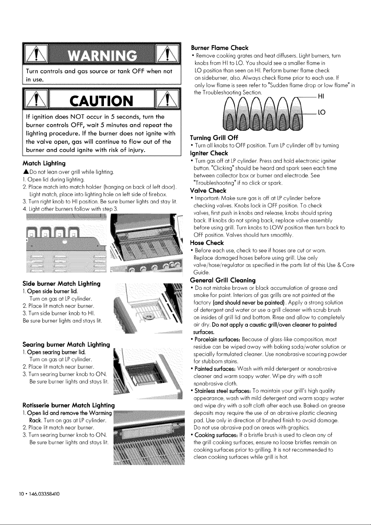
Burner Flame Check
• Remove cooking grates and heat diffusers Light burners, turn
knobs from HI to LO_You should see a smaller flame in
LO position than seen on HL Perform burner flame check
on sideburner, aiso. Always check flame prior to each use. if
only low flame is seen refer to "Suddenflame drop or low flame" in
the Troubleshooting Section.
Turning Grill Off
• Turn all knobs to OFF position Turn LPcylinder off by turning
Igniter Check
• Turn gas off at LPoilinder Press and hold electronic igniter
button. "Clicking" should be heard and spark seen each time
between collector box or burner and electrode. See
"Troubleshooting"if no click or spark_
Valve Check
• Important: Make sure gas isoff at LPcylinder before
checking valves° Knobs lock in OFF position. To check
valves, first push in knobs and release, knobs should spring
bacL tf knobs do not spring back, replace valve assembly
before using grill Turn knobs to LOW position then turn back to
OFF position_Valves should turn smoothly_
Hose Check
• Before each use, check to see if hoses are cut or worn_
Replace damaged hoses before using grill Use only
valve/hose/regulator asspecified in the parts list of this Use & Care
Guider
General Grill Cleaning
• Do not mistake brown or black accumulation of grease and
smoke for paint Interiors of gas gri!ls are not painted at the
factory (and should never be painted) Apply a strong solution
of detergent and water or use a grill cleaner with scrub brush
on insides of grili lid and bottom_ Rinseand allow to completely
air dry Do not apply a caustic grill/oven cleaner to painted
surfaces.
•Porcelain surfaces: Because of glass-like composition, most
residue can be wiped away with baking soda/water solution or
specially formulated deaner_ Use nonabrasive scouring powder
for stubborn stains.
• Painted surfaces: Wash with mild detergent or nonabrasive
cleaner and warm soapy water. Wipe dry with a soft
npnabrasive doth_
° Stainless steel surfaces: To maintain your grilFs high quality
appearance, wash with mild detergent and warm soapy water
and wipe dry with a soft cloth after each use. Baked-on grease
deposits may require the useof an abrasive plastic cleaning
pad Use only in direction of brushed finish to avoid darnage_
Do not use abrasive pad on areas with graphics_
• Cooking surfaces: If a bristle brush isused to clean any of
the grill cooking surfaces, ensure no loose bristles remain on
cooking surfaces prior to gri!ling Itis not recommended to
clean cooking surfaces while grill is hot.
10" 146.03358410
Page 11
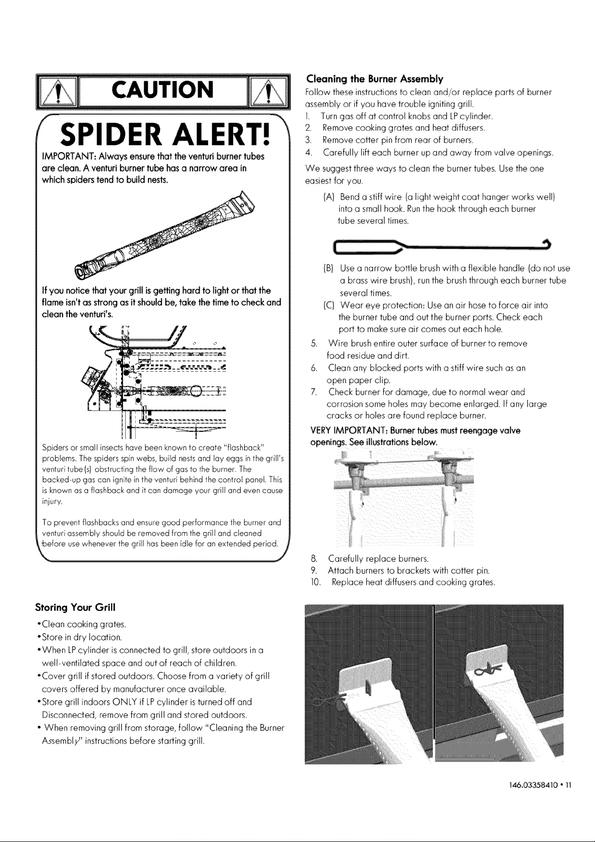
SPIDER A| ERr!
IMPORTANT:Always ensurethattheventuriburnertubes
are clean. A venturiburnertube hasa narrow area in
whichspiderstend to build nests.
If you notice thatyour grill isgetting hard to fight or that the
flame isn'tasstrong asitshouldbe,take the time to checkand
cleanthe venturi's.
Spidersor small insectshave been knownto create "flashback"
problems. Thespidersspinwebs, build nestsand tay eggs inthe grill's
venturitube(sl obstructing the flow of gas to the burner The
backed-up gascan ignitein theventuri behindthe controi panel This
isknown asa flashback and it can damage your grill and even cause
iniury
Cleaning the Burner Assembly
Followtheseinstructionsto clean and/or replace partsof burner
assemblyor if you have trouble ignitinggrill
L Turngas off at control knobsand LPcylinder.
2, Removecookinggrates andheatdiffusers,
3. Removecotter pinfrom rear of burners,
4. Carefully lift each burnerupand away from valve openings.
We 9uggestthree waysto clean the burnertubes.Usethe one
easiestfor you.
(A) Benda stiffwire (a lightweight coat hangerworkswdi)
intoa smallhook.Runthe hook througheach burner
tube severaltimes.
(B) Use a narrow bottle brush with a flexible handle (do not use
a brass wire brush), run the brush through each burner tube
several times.
(C) Wear eye protection: Use an air hose to force air into
the burner tube and out the burner ports. Check each
port to make sure air comes out each hole.
5. Wire brush entire outer surface of burner to remove
food residue and dirt.
6. Clean any blocked ports with a stiff wire such as an
open paper clip.
7. Check burner for damage, due to normal wear and
corrosion some hobs may become enlarged. If any large
cracks or holes are found replace burner.
VERYIMPORTANT: Burner tubes must reengage valve
openings. See illustrations below.
To preventflashbacksand ensuregood performance the burner and
venturiassemblyshould be removed from thegriil and cleaned
'before usewhenever the grill hasbeen idIe for an extended period
Storing Your Grill
• Clean cooking grates.
• Store in dry location.
• When LPcylinder is connected to grill, store outdoors in a
well-ventilated space and out of reach of children.
• Cover grill if stored outdoors. Choose from a variety of grill
covers offered by manufacturer once available.
• Store grill indoors ONLY if LPcyJinder is turned off and
Disconnected, remove from grill and stored outdoors.
• When removing griJlfrom storage, follow "CJeaning the Burner
A_embl;7 instructions before starting griJi.
& Carefu@ replace burners
9 Attach burners to brackets with cotter pin.
10 Replace heat diffusers and cooking grates.
146.03358410 " 11
Page 12
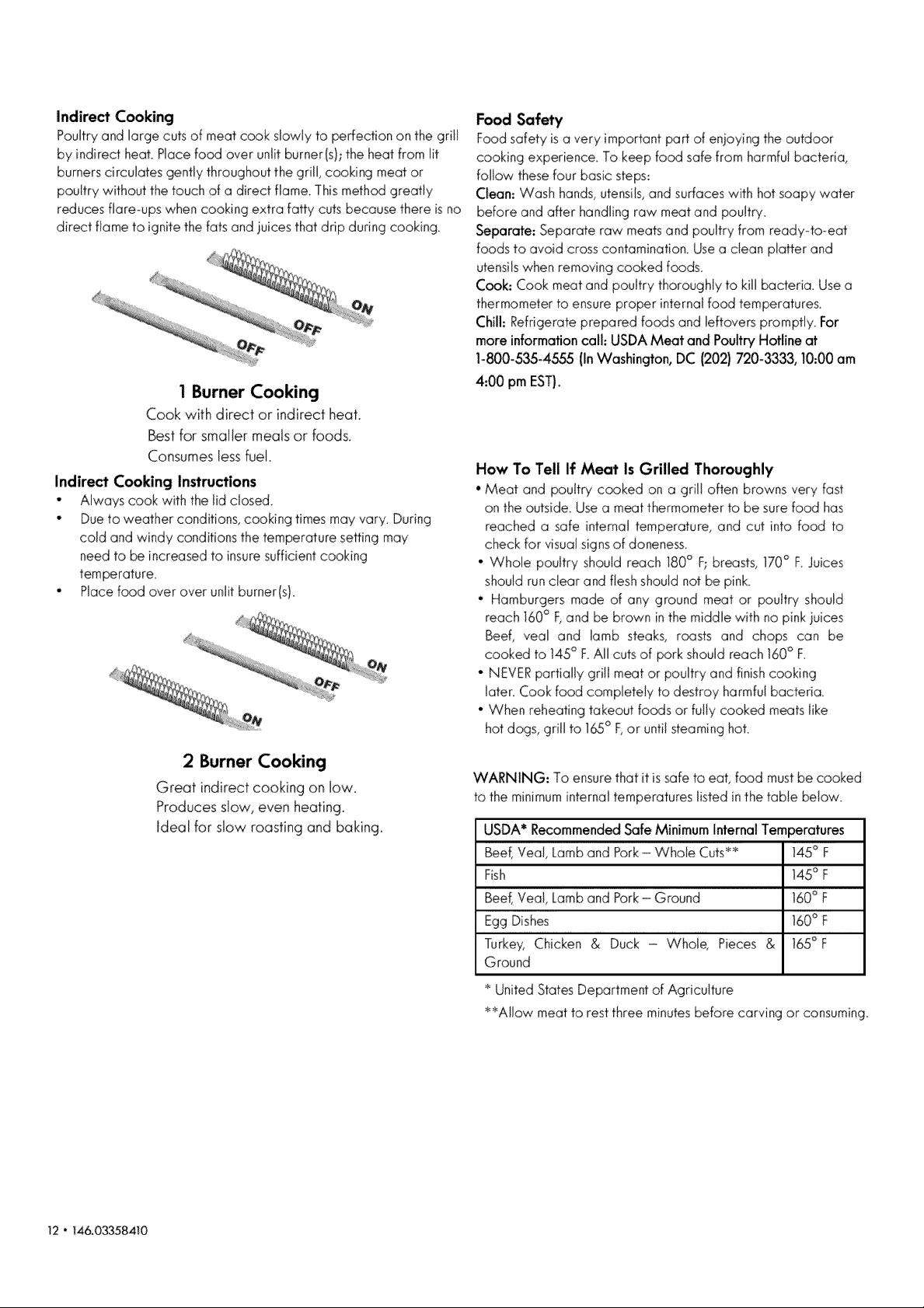
Indirect Cooking
Poultry and large cuts of meat cook slowly to perfection on the gri!l
by indirect heat. Place food over unlit burner(s/; the heat from lit
burners circulates gently throughout the grill, cooking meat or
poultry without the touch of a direct flame. This method greatly
reduces flare_ups when cooking extra fatty cuts because there is no
direct flame to ignite the fats and iuices that drip during cooking.
1 Burner Cooking
Cook with direct or indirect heat.
Best for smaller meals or foods.
Consumes Jessfuel.
Indirect Cooking Instructions
• Always cook with the lid closed.
• Due to weather conditions, cooking times may vary. During
cold and windy conditions the temperature setting may
need to be increased to insure sufficient cooking
ternperature,
• Place food over over unlit burner(s).
Food Safety
Foodsafety isa very importantpart of enjoying the outdoor
cooking experience. To keep food safefrom harmfu!bacteria,
follow thesefour basic steps:
Clean: Wash hands,utensils,and surfaceswith hotsoapy water
before and after handlingraw meat andpoultry.
Separate: Separate raw meatsand poultry from ready-to-eat
foods to avoid crosscontamination.Usea clean platter and
utensilswhenremovingcooked foods.
Cook: Cook meat and poultry thoroughlyto kill bacteria. Usea
thermometerto ensureproper internalfood temperatures.
Chill: Refrigerateprepared foods and leftoverspromptly. For
more informationcall: USDAMeat and PoultryHotline at
1-800-535-4&55 (InWashington,DC (202) 720-3333,10:00 am
4:00 pmEST),
How To Tell If Meat Is Grilled Thoroughly
' Meat and poultry cooked on a grill often browns very fast
on the outsider Use a meat thermometer to be sure food has
reached a safe internal temperature, and cut into food to
check for visual signs of doneness.
• Whole poultry should reach I80 ° F;breasts, 170° F_Juices
should run clear and flesh should not be pink,
• Hamburgers made of any ground meat or poultry should
reach 160° Band be brown in the middle with no pink juices
Beef, veal and lamb steaks, roasts and chops can be
cooked to 145° F_All cuts of pork should reach 160° F.
• NEVER partially grill meat or poultry and finish cooking
later. Cook food completely to destroy harmful bacteria.
• When reheating takeout foods or fully cooked meats like
hot dogs, grill to 165° F,or until steaming hot
2 Burner Cooking
Great indirect cooking on low.
Produces slow, even heating.
Ideal for slow roasting and baking_
WARNING: To ensure that it is safe to eat, food must be cooked
to the minimum internal temperatures listed in the table below.
USDA* Recommended Safe Minimum Internal Temperatures
Beef, Veal, Lamb and Pork - Whob Cuts_ !45 ° F
Fish 145° F
Beef, Veal, Lamb and Pork- Ground 160° F
Egg Dishes 160° F
Turkey, Chicken & Duck - Whole, Pieces & 165°F
Ground
United States Department of Agriculture
_:_AIIow meat to rest three minutes before carving or consuming.
12 - 146.03358410
Page 13
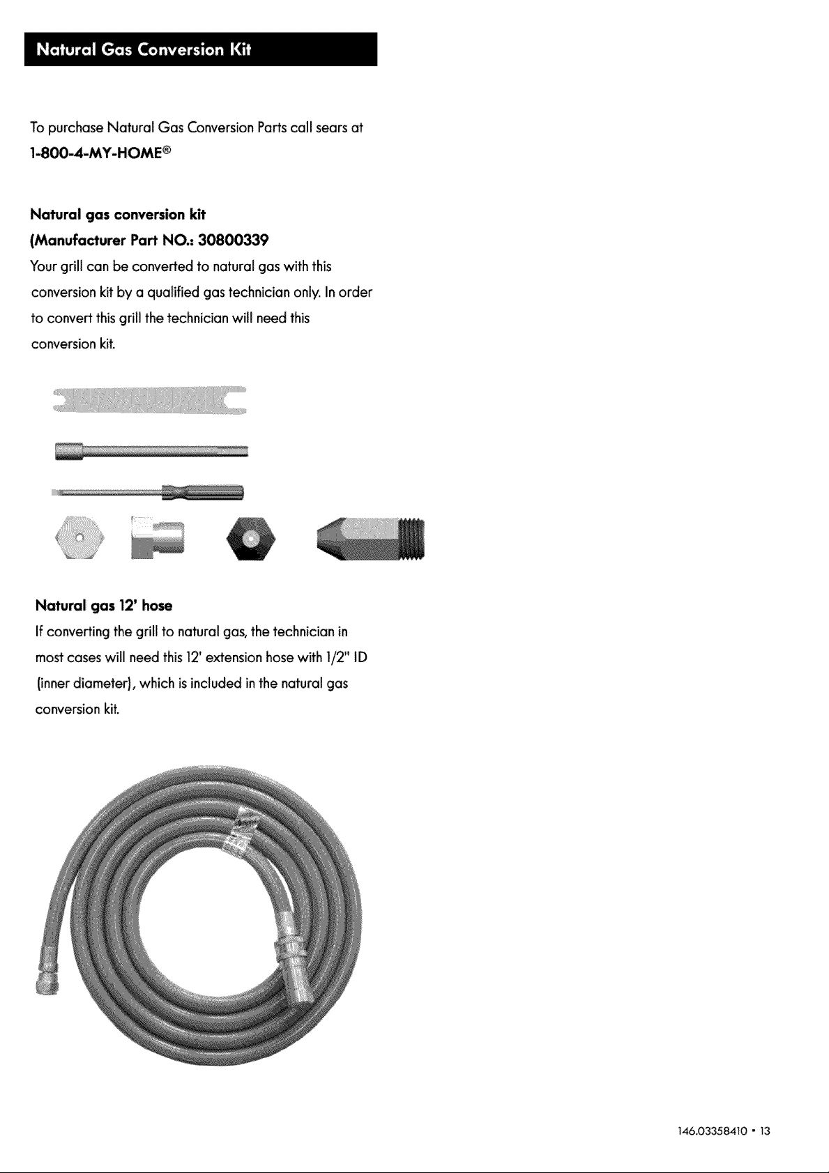
To purchase Natural Gas Conversion Parts call sears at
1-800-4-MY-HOME ®
Natural gas conversion kit
(Manufacturer Part NO.- 30800339
Your grill can be converted to natural gas with this
conversion kit by a qualified gas technician only. In order
to convert this grill the technician will need this
conversion kit.
Natural gas 12' hose
If converting the grill to natural gas, the technician in
most cases will need this 12_extension hose with 1/2" ID
(inner diameter), which isincluded in the natural gas
conversion kit.
146.03358410 - 13
Page 14

For Natural Gas Connection
Preparing:
1. Turnoff gas supply,and then remove cap on gas
Supply side.
2. Recommended: install a shut-offvalve on
gas supply side before installingthe socket.
3. Socket should be installed by an authorized
technician in accordance with the national fuel gas
code (NFPA 54/ANSI223.1)
4. Before insertingplug, turn on gas supplyand leak
test all connections including the stemof the shut-off
valve and the opening of the socket. For best results,
use and ammonia-free soap & water solution.
Gas Requirements
LP Gas
If your grill is for LPGas, the regulator supplied is set for
an N-in. Water column (WC) and is for use with LPgas
only. The factory-supplied regulator and hose mustbe
used with a 20-lb. LPgas tank.
Natural Gas
If your grill is for Natural Gas, it is set for a 7-in. water
column (WC) and isfor usewith Natural Gas only. Gas
pressure is affected by gas line size and the length of
gas line run from house gas line. Follow the
recommendations in the chart below.
From House to G_lJ
Operating Instructions"
1.To connect, push back socket sleeve.
2. Insert plug and release sleeve.
3. Pushplug untilsleeve snaps forward. (Gas will flow
automatically. Failure to connect plug properly to
socket will inhibit gas flow to the appliance.)
_t
Distance Tubing Size
Up to 25 ft. 3/8 in. diameter
26-50 ft. 1/2 in. diameter
51-100 ft. 2/3 of the run: 3/4 in. diameter
1/3 of the _n: 1//2 in. diameter
Over 101 ft. 3/4 in. diameter
To disconnect
1. Pull Sleeve back. Pull plug out socket. (Gas is
automatically shutoff.)
2. Close shut-off valve and replace dustcaps on socket
and plug.
t4 - 146.033584_0
Page 15

Key Description Qty
1 Lid, Side Burner 2
2 Rotate Rod, Side Burner 2
3 End Cap, RightSide Shelf 1
4 Right Side Shelf 1
5 Cooking Grid, Side Burner 1
6 Searing Burner Base 1
7 Grease Cup ,Searing Burner 1
Pad Number
41500041
41500205
30800206
50600033
50600203
50600036
50600039
Key Description Qty
35 Regulator 1
36 Hose Retaining Clip 1
37 Control Knob Bezel 7
38 Contrd Knob Bezel, Rotisserie Burner 1
39 Contrd Knob, Rotisserie Burner 1
40 Contrd Knob, Searing Burner 1
41 Control Knob 6
Part Number
50600233
30800226
40900036
50403001
50600218
50600217
30800219
8 Double Igniter Wire, Searing 1
Burner
9 Fascia, RightSide Shelf 1
10 Searing Burner 1
11 Side Shelf Badge 1
12 Control Panel 1
13 Control Panel Inner Panel 1
14 Led LightStrip 1
15 Ground Wire 1
16 Control Panel Glass 1
17 Pulseground wire 2
18 Switch Box 1
19 Waterproof Switch 2
20 Gas Valve, Side Burner 1
21 Thermocouple Assembh, 1
22 Gas Hose B 1
23 Side Burner Hose 2
24 Pulse Control Wire 1
25 Safety Switch 1
26 Gas Valve, Main Burner 5
27 Gas Valve, Searing Burner 1
28 Manifold, Side Burner 2
29 Manifold, Rotisserie Burner 1
30 Manifold, Main Burner 1
31 Gas Hose 1
32 Gas Hose A 1
33 Regulator Retention Bracket 1
34 Connector B 1
50600225
50600041
50600081
50600201
50600019
50600023
50600230
61300096
50600202
30800244
41500221
41500220
41500208
50600214
50600215
41500228
50600226
50600213
50600211
50600212
41500042
50600030
50600024
50600232
50600234
30800054
30800218
42 Bottom Shelf
43 Top Magnet Box 1
44 Magnet 4
45 Bottom Magnet Box 1
46 Caster 2
47 Caster with Brake 2
48 Cart Support Angel Bar 2
49 Fuel Gauge 1
.50 Tank Positioning Pin 2
.51 Grease Box 1
52 Door Bracket 1
53-1 Right Side Panel (Carbon Grey 1
Metallic}
53-2 Right Side Panel (Maroon Metallic} 1
.53-3 Right Side Panel (Silver} 1
54 Battery Module 1
55 Battery Box 1
56 Door Hinge 4
57 Match Holder 1
58 Match Holder Bracket 1
59 Match Holder Chain 1
60 Door Handle 2
61-1 Right Door (Carbon Grey Metallic) 1
61-2 Right Door (Maroon Metallic) 1
61o3 Right Door (Silver) 1
62ol Left Door (Carbon Grey Metallic) 1
62-2 Left Door (Maroon Metaliicl 1
62-3 Left Door (Silver) 1
50600072
50600057
40200094
50600076
30800238
30800237
50600058
30800087
30800229
30800082A
50600056
50600051A
50600051B
50600051C
41500223
50600050
30800236
40800128
40800129
50600231
50600069
50600066A
50600066B
50600066C
50600060A
50600060B
50600060C
146.03358410 " 15
Page 16

Key Description
Left Side Panel (Carbon Grey
63-1
Metallic)
Left Side Panel (Maroon
63-2
Metallic)
63-3 Left Side Panel (Silver)
Qty
Number
1
50600045A 90
1
50600045B 91
1
50600045C 92
Part Key
Motor
RotisserieRod
Fork
Description
Qty
1
1
2
Part Number
50600210
50600206
50600207
64 Tank Baffle
65 Transformer
66 Three legs power line
67 Wire Slot C
68-1 Back Panel (Black)
68-2 Back Panel (Silver)
69 Hole Bushing
70 Electronic Ignition Module
71 Main Burner Electrode L345
72 Main Burner Electrode L500
73 Main Burner Electrode L715
74 Main Burner Electrode L560
75 Main Burner Electrode L405
76 Grease Tray
77 Lamp Seat
78 Thermocouple Bracket
79 Motor Support Bracket
80 Motor Support
81 Main Burner
82 Fascia, LeftSide Shelf
2 50600074 93
1 41500216 94
1 50600229 95
1 50600049 96
1 50600055A 97
1 50600055B 98
2 30800245 99
2 61200215 100
1 50600219 10]
1 50600220 102
1 50600223 103
1 50600222 104
1 50600221 ]05-1
1 50600014 105-2
2 41500021 105-3
1 50600028 106
1 50600026 107
1 50600027 108
5 30800086 109
1 41500044 110
Wing Screw, Flat Head Set Screw
Shaft Collar
LidRubber Bumper, Front
LidRubber Bumper, Back
Temperature Gauge
Temp Gauge Bezel
Logo
Rotate Rod, Lid
LidHandle Spacers
Bezel, Lid Handle
Cotter Pin
LidHandle
Lid (Carbon Grey Metallic)
Lid (Maroon Metallic)
Lid (Silver/
RearPanel, RotisserieBurner
Lamp
RotisserieBurner
Wire SHotA
Wire Slot B
1
2
2
1
1
1
2
2
2
7
1
1
1
1
]
2
1
1
2
50600209
50600208
30800233
40800107
30800207
30800208
30800209
40800108
30800231
30800011
110050
50600006
50600002A
50600002B
50600002C
50600029
41500218
50600080
50600013
41500015
83 igniter Wire, Side Burner
84 Side burner bracket C
85 Side Burner Base
86 Cooking Grid, Side Burner
87 Side Burner
88 End Cap, Left Side Shelf
89 Left Side Shelf
Not Pictured
Hardware Pack
Manual
16 " 146,03358410
] 41500213 111
1 41500040 112
1 41500036 113
1 41500203 114
1 41500224 ]15
1 30800205 116
1 41500030 117
1
50600330
1
50600322A
Warming Rack
Cooking Grate
Heat Diffuser
Double igniter Wire, Rotisserie Burner
Firebox
Side Burner Hose Fixed Bracket
PulseDecoration Box
1
3
5
1
1
2
2
if you are missinghardware or have
damaged parts after unpacking grill,
call 1-888-287-0735 for replacement.
To order replacement parts after using grill,
call 1-800-4-MY-HOME ®
50600204
50600205
41500013
50600224
50600008
50600085
30800246
Page 17

©
@
®
@
146.03358410 " 17
Page 18
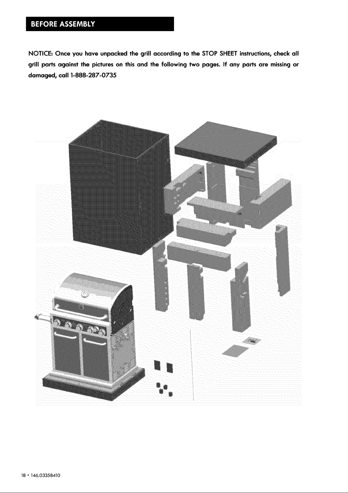
NOTICE: Once you have unpacked the grill according to the STOP SHEET instructions, check all
grill parts against the pictures on this and the following two pages. If any parts are missing or
damaged, call 1-888-287-0735
_8 " _46.03358410
Page 19

Page 20

20-146,033584_0
Page 21

CAREFULLY READ AND PERFORM ALL ASSEMBLY INSTRUCTIONS ON THE FOLLOVClNG PAGES.
Tools Required:
[] Adjustable wrench (not provided)
[] #2 and #3 Philips Screwdriver and Slotted Screwdriver (not provided)
[] The following hardware is provided in blister pack for convenient use.
M4XlO Screws
Qty.. 2 pcs
M6X13 Screws
Qty: 10 pcs
M4X12 Screws
Qty.. 2 pcs
AA Battery
_y: 6 pcs
146.03358410" 21
Page 22

Left Side Shelf Assembly
[] Hang shelf onto brackets on bft side of firebox. (A)
[] Attach shelf to firebox from inside with (2) M6x13 screws. (B)
[] Attach shdf to firebox from outside with (3) M6x13 screws and (1) M4x12 screw. (C)
M6X13 screws Qty: 5 pcs
M4X12 screws Qty: 1 pc
A
B
C
22- 146,03358410
Page 23

Right Side Shelf Assembly
[] Hang shelf onto brackets on right side of firebox. (A)
[] Attach shdf to firebox from inside with (2) M6x13 screws, (B)
[] Attach shdf to firebox from outside with (3) M6x13 screws and (1) M4x12 screw. (C)
A
M6X13 screws
M4X12 screws
Qt,/: 5 pcs
Qty: 1pc
B
/" \,
\, /
\
°oIt
\
C
@
i46.03358410- 23
Page 24

Le_ Side burner
D Remove plastic packaging from side burner valve. Remove side burner grate from within
side burner shelf.
D Connect fnatigniter wire tip to the igniter pin on the side burner valve. (A & B)
D Remove the 2 prednstalled screws from the valve control stem and set them aside. (C/
D Loosen the side burner to insert gas valve. To loosen, remove the two screws on front bracket,
and loosen the rear bracket screws halfway. (D&E}
D Insert the gas valve into the side burner (F}, and insert the valve control stem through the hole
in shelf fascia. (I)
D Replace side burner front bracket and tighten in place with 2 previously removed screws. (G)
Tighten screws on back bracket. (H)
D Install previously removed 2 screws .Note:Do not tighten these 2 screws until the bezel isattached
to fascia and valve face. (I).
D Attach bezel to facial and valve face with the insta!led screws .First attach one side key hole of
bezel to the screw ,then attach the other one to the other screw.Make sure the black mark faces
up.(J1.Tighten the 2 screws. (K}
D Pushcontrol knob onto side burner valve stem. (L} Replace side burner grate. (M)
D Connect the round igniter wire tip to the pin on the white electrode protruding from the bottom
of the side burner shelf. (NI
24" 146.03358410
Page 25

I_03358410" 25
Page 26

Right Side Searing burner
Remove plastic packaging from searing burner valve. Remove searing burner grate from within
searing burner shelf_
Connect flat igniter wire tip to the igniter pin on the searing burner valve. (A & Bf
D Remove the 2 prednstalled screws from the valve control stem and set them aside, (C1
Loosen the searing burner to insert gas valve. To loosen, remove the screw attaching the
electrode (DI to the shelf and set both aside. Then loosen and remove the two screws hNding
searing burner in place (E).
D Insert the gas valve into the searing burner (F},and insert the valve control stem through the hone
in shdf fascia. (I)
D Reattach searing burner to side shelf with the 2 previously removed screws (G)° Reattach
electrode to side shelf with previously removed screw (H).
Install previously removed 2 screws _Note: Do not tighten these 2 screws untinthe bezel is
attached to fascia and valve face.(I).
D Attach bezel to facial and valve face with the installed screws .Firstattach one side key honeof
bezel to the screw ,then attach the other one to the other screw. Make sure the black mark
faces up. Tighten the 2 screws. (J)
Pushcontrol knob with red indicator mark onto side burner valve stem. (K)
D RepJace searing burner grate, (L)
D Slide searing burner grease box into the grease box bracket. (MI
Connect the round igniter wire tip to the pin on the white electrode protruding from the bottom of
the searing burner shelf. (N)
26 " 146.03358410
Page 27

146_03358410 * 27
Page 28

Tank Baffle Assembly
[] Insert tank baffle bar tip with oval hob over oval tab on underside of grease tray bracket (A}.
D Turn bar to right to Uocktip in place (B).
[] Secure other tip of bar to gdH bottom shelf with (1) M4xlO screw (C).
G Repeat above steps for other tank baffle bar (D}.
M4X10 screws Qty: 2 pcs
A
C
D
28 - 146.03358410
Page 29

Grease Tray and Grease Box
[] From front of grill, slide grease tray onto grease tray brackets underneath firebox (A1. Make sure
grease drainage hole is on left side (BJ.
[] Shde grease box into grease box bracket as shown. (C/(D)
A
[]
I
/
[]
/
\,
D
/
/
/
[]
t°1
cAuTioN
Failure to install grease box will cause
hot grease to drip from boffom of grill
with risk of fire or property damage.
146.03358410 - 29
Page 30

Heat Diffusers, Cooking Grate and Warming Rack
D Place heat diffusers over burners. The heat diffusers will fit in firebox in either direction_ Fit tabs
in firebox front through slots in diffuser tips, Fitdiffuser tips inside tabs in firebox rear. (A)
D Place cooking grates onto grate rests. (B)
D Insert 'warming rack into brackets at top of firebox as shown. (C)
A
C
30- 146.03358410
Page 31

Door Adjustment (Left door shown}
o Remove the screw cover from the upper and lower hinges to expose the adjustment screws (A).
[_ To adjust the gap between the doors, turn the outer screws countercbckwbe to increase the
gap, and clockwise to decrease the gap (A & B).
To adjust the gap between the door and the cart, loosen the inner screws, then move the door to
the desired position and retighten the screws (C).
A B
\
\
C
146,03358410 - 31
Page 32

Gas Tank Installation
[] LPtank issold separateh/.
[] Place LPtank onto fuel gauge with tank collar opening facing to the left as shown_
Firsthang tank collar opening over hook in face of gauge. Then rotate gauge latch down over
cdlar and tighten wing nutto secure collar in place.
[] Connect the regunator and hose to the tank as shown. Make sure that hose is dipped to
underside of fuengauge.
32 " 146.03358410
Failure to install tank correctly may allow
gas hose to be damaged in operation.
Page 33

Safety Notice - Lock Caster Brakes
[] When the grill in the desired location, bck the caster brakes; this wilt help the grill stay in
place for safe operation.
\
i46.03358410- 33
Page 34

Rotisserie Kit Assembly (Rotisserie motor on left side as shown}
Remove warming rack from firebox. Insert motor support into motor support bracket
preassembJed to left side of firebox (A/.
insert rotisserie motor onto motor support (B}. Make sure to insert motor with power cord at
bottom,
Slide the shaft coiiar onto the rotisserie rod followed by the two forks (forks shoundbe
pointing toward each other). Make sure that shaft collar is positioned near rounded end of
rotisserie rod. Tighten Wing Screw, Hat Head Set Screw on shaft collar and forks, but do not futty
tighten in this step. (C)
D Insert the pointed end of the rotisserie rod into the hole for it in the motor. On the other end of the
rod, slide the shaft collar to the point where the groove in the collar will lay secureJy in the slot in
the firebox wall (D). Fully tighten the collar Wing Screw, Hat Head Set Screw with slotted
screwd river.
D The rotisserie motor can be assembled on either the left and right side of firebox. If you need to
use the rotisserie and side burner at the same time, you may position the motor over the searing
burner side of the grill Remove motor, motor support and motor support bracket and reassemble
to the other side of firebox. To detach bracket, remove the two screws and use them to attach the
bracket to the other side.
A
\
\
C
D
34 "146.03358410
Page 35

Batteries
a Unscrew the igniter caps from the cart side panels as shown below (A & B).
D insert (1)AA battery into each battery slot with the positive (+ } battery pole facing outward (C).
[] Screw igniter caps back on (D).
146.03358410 ° 35
Page 36

Control Panel LEDLight Battery Assembly
[] Lift battery module out of battery box on inside of left cart panel (A). Disconnect plug between
wires to free the module for battery insertion (B).
[] Remove battery module cover (C). Insert (4} AA batteries into battery slots in orientation as
shown (D), Replace module cover (E).
[] Reconnect plug between wires (FI. Replace battery module into battery box (GI. Make sure
that battery module switch is turned to ON (H).
36 " 146.033584_0
Page 37

Note: If the lamps on the inside rear of the firebox do not work,
follow the steps below to replace them.
Remove the rear panel screw and nuts
Remove the lamp screw and nuts
Take the rear panel out
Loosen the lamp from lamp seat
Take the lamp out from rear of lamp seat
Pressthe button to remove the lamp glass
146.03358410 " 37
Page 38

Remove the rejected lamp bulb Replace the new lamp bulb
Instali the lamp glass back
Install the screw and nut back
38 - 146,03358410
Install the lamp back to lamp seat
Install the rear panel screw and nut back
Page 39

EMERGENCIES: If a gas leak cannot be stopped, or a fire occurs clue to gas leakage, call the fire department.
Gas teaking from
hose
Gas leaking from LP
cyIinder.
Gas teaking from LP
cylinder vaIve.
Gas leaking between Lf
cyiinder and regulator
connection
Firecoming through
control panel
Grease fire or
continuous excessive
flames above cooking
Troubleshooting
Burner(s) will not light
using igniter
(See Electronic
Ignition
Troubleshooting also)
Continuedon next
page_
• Damaged hose
• Mechanical failure due to rusting or
mishandling
• Failureof cylinder valve from
mishandlingor mechanicalfailure
• Improper installation, connection not
tight, failure of rubber seal.
• Fireinburnertubesectionof burner
dueto blockage.
• Too much grease buildup in burner
area
GAS ISSUES:
" Trying to light wrong burner
• Burner not engaged with control
valve.
• Obstruction in burner.
° No gas flow.
•Turn off gas at LPcylinder or at source on natural gas systems.
Ifthe hose is cracked or cut but not burned, simply replace
valve / hose / regulator_ If the hose is burned, the cause could
be other than a faulty valve/hose/regulator: Discontinue use of
grill until a plumber or gas technician has investigated and
corrected the problem
• Replace LPcylinder_
• Turn off LPcylinder valve Return LPcylinder to gas supplier
•Turn off LPcylinder valve. Remove regulator from cylinder and
visually inspect rubber seal for damage See LPCylinder Leak
Test and Connecting Regulator to the LPCylinder
•Turn off contrd knobs and LPcylinder valve. Leave lid open to
anlow flames to die down After fire isout and gri!t is cold,
remove burner and inspect for spider nests or rust. See Spider
Alert and Cleaning the Burner Assembly sections of this Use &
Care Guide
• Turn off control knobs and LPcylinder valve. Leave lid open to
allow flames to die down After cooling, clean food particles
and excess grease from inside firebox area, grease tray, and
other surfaces.
• See instructions on control panel and in Useand Care sectiom
° Make sure valves are positioned inside of burner tubes
• Ensureburnertubesare not obstructedwith spider webs or
other matter Seecleaningsectionof Useand Care
° Make sure LPcylinder is not empty If LPcylinder is not empty,
refer to "Sudden drop in gas flow."
• Vapor lock at coupling nut to LP
cylinder.
•Coupiing nut and LPcylinder valve not
fully connected
° Electrode cracked or broken; "sparks
at crack_
° Electrode tip not in proper positiom
° Wire and/or electrode covered with
cooking residue
• Wires are bose or disconnecte4
• Wires are shorting(sparking)
between igniter and electrode
• Dead battery_
° Turnoff knobsand disconnectcouplingnutfrom LPcylinder
Reconnectandretry_
• Turn the coupling nut approximately one-half to three-quarters
additional turn until solid star Tighten by hand only - do not use
tools
• Replace electrode(s).
Main Burners:
° Tip of electrode should be pointing toward gas port opening
on burner The distance should be 1/8'_to 1/4" Adjust if
necessary
Sideburner;SearingBurnerand RotisserieBurner:
°Tipofelectrodeshouldbe pointingtowardgas port opening
on burnerthedistanceshouldbe I/8"to 3/16"Adjustif
necessary
• Clean wire and/or electrode with rubbing alcohol and clean
swab.
° Reconnect wires or replace electrode/wire assembly
• Replace igniter wire/eiectrode assemNy.
146.03358410" 39
Page 40

Troubleshooting (continued)
Burner(s) will not light
using igniter,
(See Electronic
Ignition
Troubleshooting also)
ELECTRONICIGNITION:
• No spark,noignitionnoise.
• No spark,someignition noise_
• See Section t of Electronic Ignition System.
• See Section II of Electronic Ignition System,
• See Section Ill of Electronic Ignition System
• Sparks,but notat electrode or at full
strengtk
Burner(s)will not
matchlight
• See"GAS ISSUES:'"onprevious
page_
• Uselong-stemmatch (fireplace matchl_
° See"MatchoLighting'_sectionof Useand Care
° Match will notreach.
• Improper methodof match-lighting_
Sudden drop in gas • Out of gas_ • Check for gas in LPcylinder,
flow or low flame_
• Excessflow valve tripped still low, turn off knobs and LPcylinder valve Disconnect
• Vapor lock at coupling nut/LP cylinder valve, wait 30 seconds and then light grill
cylinder connection from cylinder_ Reconnect and retry.
•Turn off knobs, wait 30 seconds and light grill Ifflames are
regulator. Reconnect regulator and leak-test. Turn on LP
•Turn off knobs and LPcylinder valve. Disconnect coupling nut
Flames blow out.
Flare-up.
Persistent grease fire.
Flashback...
(firein burnertube(s)),
Unable to fill LP
cylinder.
One burner does
not light from
other burner (s),
40 ° 146,03358410
° High or gusting winds,
° Low on LPgas.
° Excess flow vatve tripped,
• Grease buildup
• Excessivefat in meat_
• Excessivecooking temperature.
• Grease trapped by food buildup
around burner system,
• Burner and/or burner tubes are
blocked
• Somedealershaveolder fill nozzles
with worn threads_
• Grease buildup or food particles in
end (s) of carryover tube (s).
° Turn front of grill to face wind or increase flame height_
° Refill LPcylinder.
• Refer to "Sudden drop in gas flow"' above.
° Cleanburnersand insideof grill!firebox.
• Trimfat from meatbefore grilling
° Adiust (lower) temperatureaccordingly.
• Turn knobs to OFF. Turn gas off at LPcylinder. Leave lid in
position and let fire burn out. After grill cools, remove and
dean all parts.
• Turn knobs to OFF. Clean burner and/or burner tubes, See
burner cleaning section of Use and Care,
• The worn nozztes don't have enough "bite" to engage the
valve. Try a second LPdealer_
/
• Cleancarry-over tube(s) with wire brush.
Page 41

Troubleshooting - Electronic Ignition
SECTION I
No sparks appear at
any electrodes when
control knob turned
to HI: no noise can
be heard from spark
module
SECTION _1
No sparksappear at
any electrodeswhen
control knob turned
to HI; noisecan be
heard from spark
module
• Battery not installed
properly.
• Dead battery.
° Buttonassemblynot
installedproperly
• Faulty spark module
• Output lead
connedions not
conneded.
• Check battery orientation
• Has battery been used
previously?
• Checkto insurethreadsare
properly engaged. Button
shouldtravel up and down
without binding_
• If no sparks are generated
with new battery and good
wire connections, module is
faulty
• Are output connections
on and tight?
• Install battery (make sure that "+" and "-"
connectors are oriented correctly, with "+" end
up and "_" end down.t
• Replace battery with new AA-size alkaline
battery.
• Unscrew button cap assembly and reinstall,
making sure threads are aligned and engaged
fully
• Replace spark module assembly.
• Remove and reconnect all output
connections at module and dectrodes_
SECTION III
Sparksare present
butnot at all
notat full strength
* Output lead
connectionsnot
connected
• Electrical arc
between output wires
and grin frame
• Weak battery.
• Electrodesare weL
• Electrode(s) cracked
or broken; sparks
appear where
cracked.
- Areoutput connectionson
and tight?
• If possible,observegrill in
dark location. Operate
ignitionsystemand look for
arcing between output
wires and grill frame
" All sparks present but
weak or at slow rate
• Hasmoistureaccumulated
on electrode and/or in
burnerports?
• Inspect electrodes for
cracks.
• Remove and reconnect al! output connections
at module and electrodes
• If sparks are observed other than from
burner(s), wire insulation may be damaged
Replace wires
• Replace battery with a new AA-size alkaline
battery.
• Use paper towel to remove moisture.
• Replace cracked or broken electrodes.
146.03358410 " 41
Page 42

Your Home
For troubleshooting, product manuals and expert advice:
managemyiife
www.managemylife.com
For repair - in your home - of all major brand appliances,
lawn and garden equipment, or heating and cooling systems,
no matter who made it, no matter who sold it!
For the replacement parts, accessories and
owner's manuals that you need to do-it-yourself.
For Sears professional installation of home appliances
and items like garage door openers and water heaters.
1-8004-MY-HOME _ (1-800-469-4663)
Call anytime, day or night (U.S.A. and Canada)
www.sears.com www.sears.ca
Our Home
For repair of carry-in items like vacuums, lawn equipment,
and electronics, call anytime for the location of your nearest
Sears Parts & Repair Service Center
1-800-488-1222 (U.S.A.) 1-800-469-4663 (Canada)
www.sears.com www.sears.ca
To purchase a protection agreement on a product serviced by Sears:
1-800-827-6655 (U.S.A.) 1-800-361-6665 (Canada)
Para pedir servicio de reparaci6n
a domicilio, y para ordenar piezas:
1-888-SU-HOGAR ®
(1-888-784-6427)
® Registered Trademark / "rMTrademark of KCD IP, LLC in the United States, or Sears Brands, LLC in other countries
® Marca Registrada / TMMarca de Fabrica de KCD IP, LLC en Estados Unidos, o Sears Brands, LLC in otros paises
MCMarque de commerce, Marque d6pos6e de Sears Brands, LLC
MD
Au Canada pour service en fran_ais:
1-800-LE-FOYER Mc
(1-800-533-6937)
wvvw.sears.ca
 Loading...