

Kenmore 141.1786, Elite 141.168600, Elite 141.178600 Owner's Manual
Owner's Manual
E L I T E
Liquid Propane Gas Grill
Model141,168600
Natural Gas Grill
Model141.178600
L_ WARNING:
Read this Owner's Manual carefully and be sure
your gas grill is properly assembled, installed and
maintained. Failure to follow these instructions
could result in serious bodily injury and/or property
damage. This gas grin is intended for outdoor use
only and is not intended to be installed in or on
recreational vehicles or boats.
Note to Installer:
Leave this Owner's Manual with the consumer
after delivery and/or installation.
Note to Consumer:
Leave this Owner's Manual ina convenient place
for future reference.
Manufacturer's Customer Service Helpline:
If there are damaged or missing parts when you
unpack this unit fromthe shippingbox, oryou have
questionsabout assembly, call us 8am - 8pm CST,
Monday through Friday at:
1-888-317-7642
Sears, Roebuck and Co.,
Hoffman Estates, IL 60179 U.S.A.
P47AIA- Date:01/10/2001
Warranty ..................................................... 2
Safety Instructions .................................... 2
Pre-Assembly Instructions ........................ 4
Hardware, Parts Diagram and Lists....5
Assembly Instructions ................................ 9
Lighting Instructions ................................. 17
Cleaning and Maintenance Instructions. 19
Frequently Asked Questions ................ 21
Cooking Instructions ............................... 22
Cooking Guide and Recipes ............... 23
Full 1-Year Warranty on Grill
For one year from the date of purchase Sears
witl repair or replace, at our option, any grill part
(except for paint loss and ignitor battery) that is
defective in material or workmanship.
Limited Warranty on Selected Grill Parts
From one year after the date of purchase for the
designated time periods listed below, Bears will
replace the following grill parts if they are defec-
tive in material or workmanship. You will be
charged for labor.
• Lifetime of Grill: Exterior Stainless Steel Parts,
Aluminum Castings (except for paint loss)
• 2 Years: Flame Tamers, Cooking Grids, Burners
• 4 Years: All Other Grill Parts (except ignitor battery)
Warranty Service
Warranty service is available by contacting your
nearest Sears Service Center.
Warranty Restrictions
• This warranty is void if grill is used for com-
mercial or rental purposes.
• This warranty applies only when the grill is
used in the United States.
• This warranty gives you' specific legal rights,
and you may also have other rights which vary
from state to state.
Sears, Roebuck and Co., Dept. 817WA,
Hoffman Estates, IL 60179
/_WARNING
Combustion by-products produced when
using this product contain chemicals known
to the State of California to cause cancer,
birth defects, or other reproductive harm.
Z_WARNING
Failure to comply with these instructions
could result in a fire or explosion that
could cause serious bodily injury, death,
or property damage.
Grill Installation Codes
This gas grill must be installed in accordance with
all local codes. In areas without local codes,
follow the latest edition of the National Fuel Gas
Code ANSI Z223.1. In Canada, installation must
conform to standard CAN/CGA lb149.1 or 1-
b149.2 (Installation Code for Gas Burning Appli-
ances and Equipment) and all local codes.
Correct LP Gas Tank Use
LP gas gdll models are designed for use with a
standard 20 lb. Liquid Propane Gas (LP gas)
tank, not included with grin box. Never connect
your gas grill to an LP gas tank that exceeds
this capacity. A tank of approximately 12 inches
in diameter by 18-1/2 inches high is the maxi-
mum size LP gas tank to use. We recommend
buying an "OPD" gas tank which offers an Overfill
Prevention Device. This safety feature prevents
the tank from being overfilled which can cause
malfunction of the LP gas tank, regulator and/or
grill.
The LP gas tank must be constructed and
marked in accordance with specific_ations of the
U.S. Dept. of Transportation (DOT). In Canada,
the LP gas tank must meet the Canadian Trans-
portation and Communications (CTC)
specifications. Also be sure:
1. The LP gas tank has a shutoff valve, termi-
nating in an LP gas supply tank valve outlet,
that is compatible with a Type 1 tank con-
nection device. The LP gas tank must also
have a safety relief device that has a direct
communication with the vapor space of the
tank.
2. The tank supply system must be arranged
for vapor withdrawal.
3. The LP gas tank used must have a collar
to protect the tank valve.
2 Sears, Roebuck and Co.
PrOlmr Placement and Clearance of Grill
Nevw use your gas grillin a garage, porch, shed,
b_way or any other enclosed area. Your gas grill is
to I_used outdoors only, at least 24 inches from the
back and side of any combustible surface. Your
gasgrill should not be placed under any surface
that will bum. Do not obstruct the flow of ventilation
air mound the gas grill housing.
Thiseutdoor gas grill isnot intended to be installed in
or ommcraational vehicles and/or boats.
/ WARNING
Failure to comply with these instructions
¢muld result in a fire or explosion that
¢mald cause serious bodily injury, death,
m" property damage.
• Never connect an unregulated LP gas tank to
jour gas gdll. The gas regulator assembly
supplied with your gas grill is adjusted to have
an outlet pressure of 11" water column (W.C.)
for connection to an LP gas tank.
• Only use the regulator and hose assembly
supplied with your gas grill. Replacement
regulators and hose assemblies must be those
specified by Sears.
• Have your LP gas tank filled by a reputable
i=opane gas dealer and visually inspected and
m-qualified at each filling.
• Never fill the gas tank beyond 80% full.
Nave your propane gas dealer check the
release valve after every filling to ensure that
it remains free of defects.
• Aways keep LP gas tanks in an upright
position.
• DOnot store (or use) gasoline or other flammable
wapors and liquids in the vicinityof this gas grill.
• /m LP gas tank that is not connected for use must
not be stored in the vicinity of this or any other gas
grill.
• Do notsubjectthe LP gas tankto excessive heat.
• Never store an LP gas tank indoors. If you
store your gas grill in the garage or other
indoor location, always disconnect the LP gas
tank first and store it safely outside.
• [P gas tanks must be stored outdoors in a
well-ventilated area. Disconnected LP gas
tanks must not be stored in a building, garage
or any other enclosed area.
• _up,_:;_your gas grill iS not in use the gas
l,:;:_t be turned off at the LP gas tank.
• "lhe regulator and hose assembly must be
inspected before each use of the grill. If there
is excessive abrasion or wear or if the hose
is cut, it must be replaced prior to the grill
being used again.
• Keep the gas regulator hose away from
hot grill surfaces and ddpping grease.
Avoid unnecessary twisting of hose. Visually
inspect hose prior to each use for cuts,
cracks, excessive wear or other damage.
If the hose appears damaged do not use the
gas grill. Call Sears at 1-800-4-MY-HOME for
a Sears authorized replacement hose.
• Never light your gas gdll with the lid closed
or before checking to insure the burner tubes
are fully seated over the gas valve orifices.
• Never allow children to operate your gdll. Do
not allow children to play near your grill.
/ WARNING
A strong gas smell, or the hissing sound of
gas indicates a serious problem with your
gas grill or the LP gas tank. Failure to
immediately follow the steps listed below
could result in a fire or explosion that could
cause serious bodily injury, death, or prop-
erty damage.
Shut off gas supply to the gas grill.
Turn the control knobs to OFF position.
Put out any flame with a fire extinguisher.
Open gdll lid.
Get away from the LP gas tank.
Do not try to fix the problem yourself.
If odor continues or you have a fire you
cannot extinquish, call your fire department.
Do not call near the LP gas tank
because your telephone is an electrical
device and could create a spark resulting
in fire and/or explosion.
3
CAUTION: Spiders and small insects occa-
sionally spin webs or make nests in the gdll
burner tubes during t]'ansit and warehousing.
These webs can lead to a gas flow ob-
struction which could result in a fire in and
around the burner tubes. This type of fire is
known as a "FLASH-BACK" and can cause
serious damage to your grill and create an
unsafe operating condition for the user.
Although an obstructed burner tube is not
the only cause of "FLASH-BACK", it is the
most common cause.
To reduce the chance of "FLASH-BACK",
you must clean the burner tubes before
assembling your grill, and at least once a
month in late summer or eady fall when
spiders are most active. Also perform this
burner tube cleaning procedure if your grill
has not been used for an extended period
of time.
To reducethe chanceof "FLASH-BACK"(see
CAUTIONon page3) cleantheburnertubesand
burnersbefore fully assembling your grill. Remove
the cotter pin from the rear underside of each
burner using a pair of long nose pliers. Carefully
lift each burner up and away from the gas valve
orifice, then refer to Figure 1 and perform one of
these three cleaning methods:
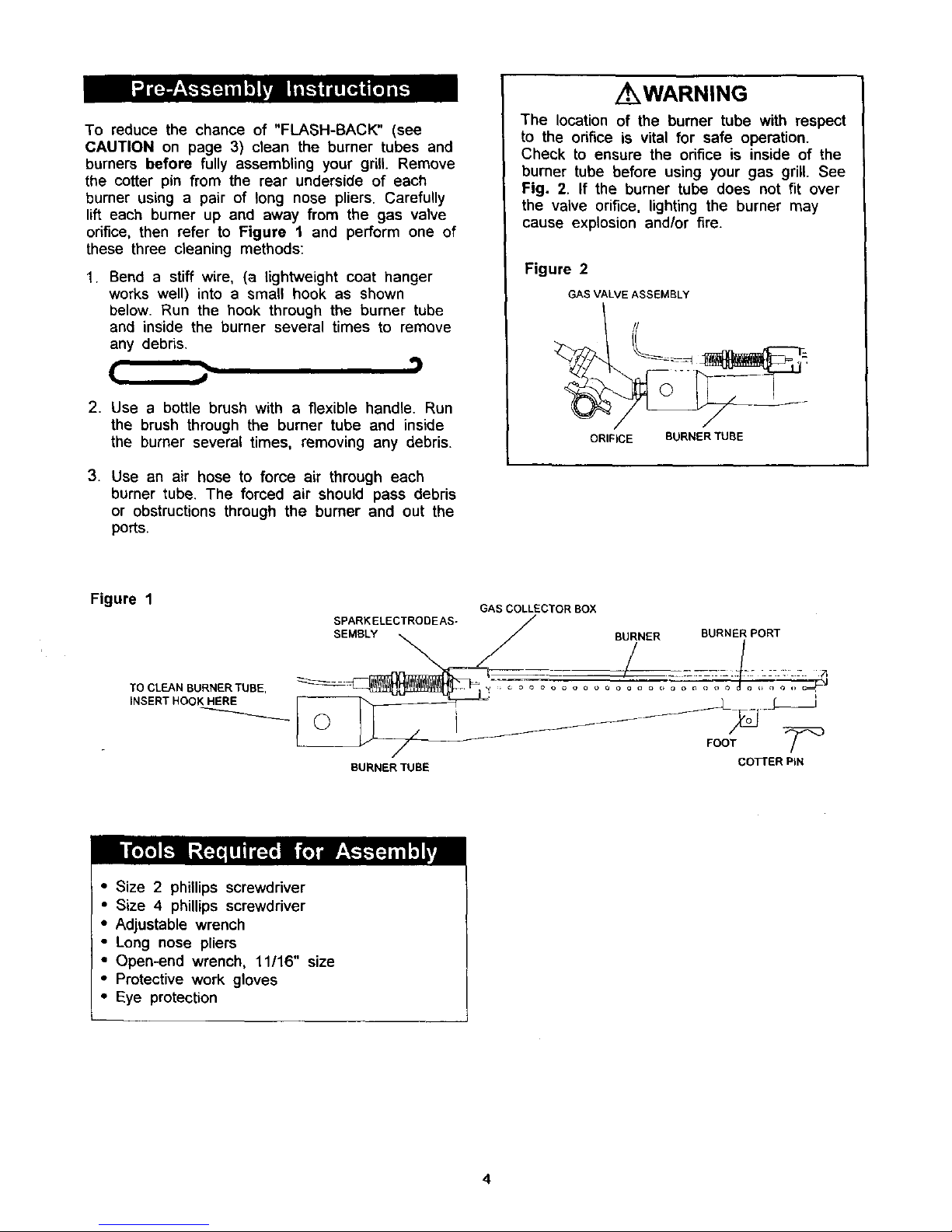
1. Bend a stiff wire, (a lightweight coat hanger
works well) into a small hook as shown
below. Run the hook through the burner tube
and inside the burner several times to remove
any debris.
( ..
2. Use a bottle brush with a flexible handle. Run
the brush through the burner tube and inside
the burner several times, removing any debris.
3. Use an air hose to force air through each
burner tube. The forced air should pass debris
or obstructions through the burner and out the
ports.
/ WARNING
The location of the burner tube with respect
to the orifice is vital for safe operation.
Check to ensure the orifice is inside of the
burner tube before using your gas grill. See
Fig. 2. If the burner tube does not fit over
the valve orifice, lighting the burner may
cause explosion and/or fire.
Figure 2
GAS VALVE ASSEMBLY
ORIFICE BURNER TUBE
Figure 1 GAS COLLECTOR BOX
SPARK ELECTRODEAS-
SEMBLY B_NER BURNEi PORT
TOCLEANBURNERTUBE, _ _ _ c_o o o o o o o o ooo c"_o'_> o o _ o o _ o ,,n _ ,, _--_
INSERT HOOK HERE [---- _ "_'=_'J='_ _ _ _ I
BURNER TUBE COl-rER BIN
• Size 2 phillips screwdriver
• Size 4 phillips screwdriver
• Adjustable wrench
• Long nose pliers
• Open-end wrench, 11/16" size
• Protective work gloves
• Eye protection
4

The following table illustrates a breakdown of the hardware pack. It highlights what components are used
in the various stages of assembly.
Ref. Component Qty. to Use
H005 1/4"x1/2" Phillips Head Screw 4
H008 1/4" Nut 4
H001 318" Wheel Bolt 2
H002 Spring Washer 2
H003 3/8" Nut 2
H005 1/4"x1/2" Phillips Head Screw 3
H008 1/4" Nut 3
H005 1/4"x1/2" Phillips Head Screw 7
H008 1/4" Nut 7
H005 1/4"x1/2" Phillips Head Screw 4
H008 1/4" Nut 4
H007 M4x6mm Phillips Head Screw 4
H006 1/4"x5/8" Part-Threaded Bolt 4
H005 1/4"x1/2" Phillips Head Screw 2
H008 1/4" Nut 2
H005 1/4"x1/2" Phillips Head Screw 2
H008 1/4" Nut 2
H005 1/4"x1/2" Phillips Head Screw 4
H012 1/4"xl-3/8" Phillips Head Screw 4
H009 1/4" Lock Nut 4
H004 1/4"x3/4" Phillips Head Screw 8
P0239A Door Handle 2
P5589A Magnetic Door Stop 2
P8080A AA BaKery 1
H015 M6 Phillips Head Screw 2
H016 M6 Nut 2
H013 M18x1.5 Nut 1
H014 M8x1.25 Nut
H005 1/4"x1/2" Phillips Head Screw
f
Purpose of Components
Install Bottom Shelf To Cart Legs
Install Wheels To Cart Legs
Install Rear Panel To Cart
Install Top Panel To Cart
Install Door Stops To Cart
Install Door Handles To Doors
Install Doors To Cart
Install Pressure Cylinder Holder To Cart
(LPG only)
Install Tank Guide To Cart (LPG only)
Restrict Drawer From Being Pulled Out Too-Far
Install Grill Head To Cart
J
i Install
Install
Install
Install
Install
Side Shelf and Side Burner To Cart
To Front Doors
To Cart
To Electric Ignitor
Tool Holder To Side Shelf
Install Pressure Cylinder To Pressure Cylinder Guide
(LPG only)
Install Tank Hook To Pressure Cylinder
LPG only)
Install Rear Wind Shield To Bowl Side Panel
5
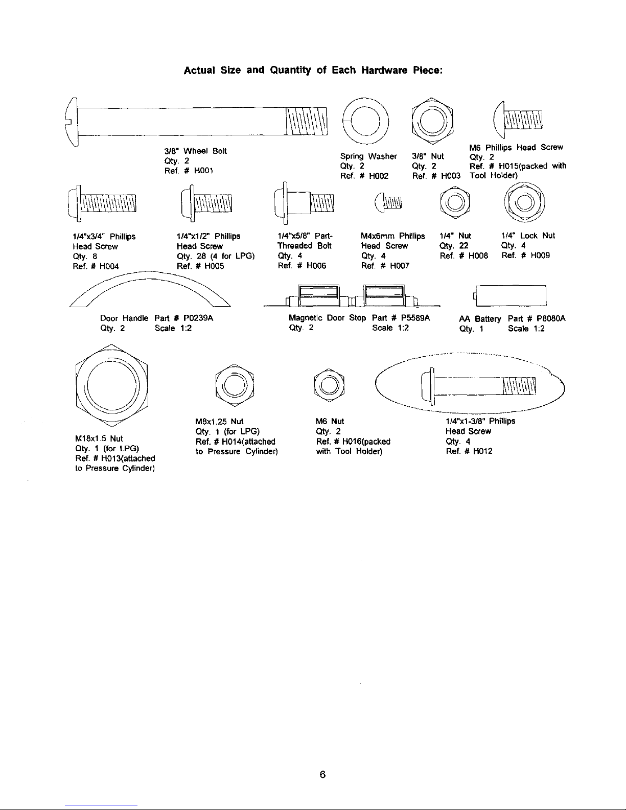
Actual Size and Quantity of Each Hardware Piece:
3/8" Wheel Bolt
Spring Washer
Qty. 2 Qty. 2
Ref. # HO01
Ref, # H002
M6 Phillips Head Screw
3/8" Nut Qty. 2
Qty. 2 Ref. # H015(packed with
1/4"x3/4" Phillips 1/4"xl/2" Phillips 114"x5/8" Part- M4x6mm Phillips
Head Screw Head Screw Threaded Bolt Head Screw
Qty. 8 Qty. 28 (4 for LPG) Qty. 4 Qty. 4
Ref. # H0O4 Ref. # HO05 Ref. # H006 Ref. # HO07
Door Handle Part # PO239A
Qty. 2 Scale 1:2
Ref. # H003 Toot Hotder)
G©
114" Nut 1/4" Lock Nut
Qty. 22 Qty. 4
Ref. # H008 Ref, # H009
Magnetic Door Stop Part # P5589A
Qty. 2 Scale 1:2
AA Battery Part # P8080A
Qty. 1 Scale 1:2
M18x1.8 Nut
Qty. 1 (for LPG)
Ref. # H013(attached
to Pressure Cylinder)
M8xl.25 Nut
Qty. 1 (for LPG)
Ref. # H014(attached
to Pressure Cylinder)
M6 Nut
Qty. 2
Ref. # H016(packed
with Tool Holder)
114"xl-3/8" Phillips
Head Screw
Qty. 4
Ref. # H012
6
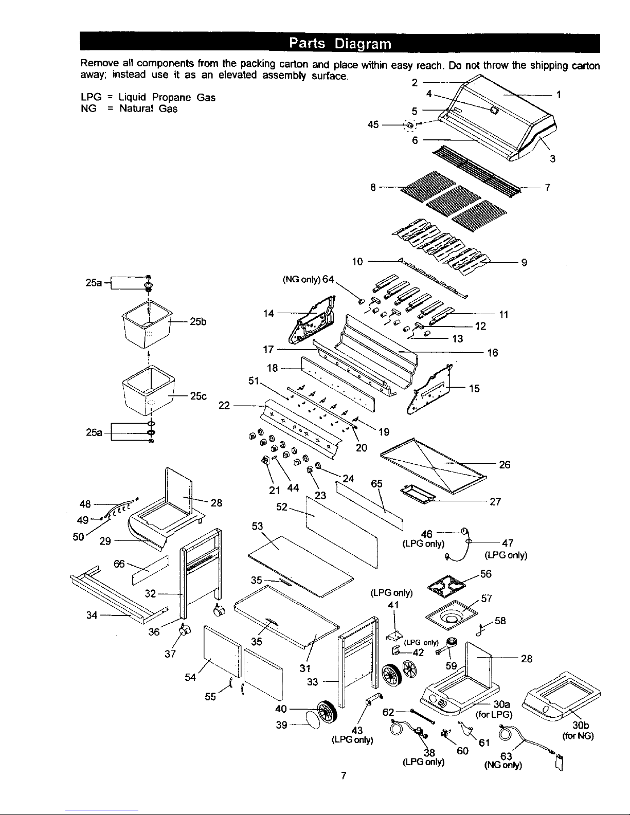
Remove all components from the packing carton and place within easy reach. Do not throw the shipping carton
away; instead use it as an elevated assembly surface.
LPG = Liquid Propane Gas
NG = Natural Gas
10
25a_ (NGonly)64,_
14--
2
5
6
11
12
13
16
25a
15
36
37
54
55
21 44
53
\
35
31
27
46
(LPGonly)-_ 47
(LPGonly)
38
(LPGonly)
7
60
(forLPG)
61
63
(NGonly)
30b
(forNG)
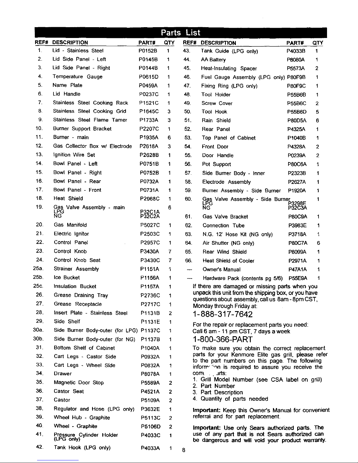
REF# DESCRIPTION PART# QTY
1. Lid - Stainless Steel PO152B 1
2. Lid Side Panel - Left P0145B 1
3. Lid Side Panel - Right P0144B 1
4. Temperature Gauge P0615D 1
5. Name Plate P0459A 1
6. Lid Handle P0237C 1
7. Stainless Steel Cooking Rack P1521C 1
8. Stainless Steel Cooking Grid P1645C 3
9. Stainless Steel Flame Tamer P1733A 3
10. Burner Support Bracket P2207C 1
11. Burner - main P1935A 6
12. Gas Collector Box w/ Electrode P2618A 3
13. Ignition Wire Set P2628B 1
14. Bowl Panel - Left PO751B 1
15. Bowl Panel - Right P0752B 1
16. Bowl Panel - Rear P0732A 1
17. Bowl Panel - Front P0731A 1
18. Heat Shield P2968C 1
19. Gas Valve Assembly - main 6
LPG P32C1A
NG P32C2A
20. Gas Manifold P5027C 1
21. Electric Ignitor P2503C 1
22. Control Panel P2957C 1
23, Control Knob P3430A 7
24, Control Knob Seat P3430C 7
25a, Strainer Assembly P1151A 1
25b, Ice Bucket P1156A 1
25c, Insulation Bucket P1157A 1
26. Grease Draining Tray P2736C 1
27. Grease Receptacle P2717C 1
28. Insert Plate - Stainless Steel P1131B 2
29. Side Shelf P1131E 1
30a. Side Burner Body-outer (for LPG) Pl137C 1
3Ob. Side Burner Body-outer (for NG) P1137B 1
31. Bottom Shelf of Cabinet P1040A 1
32. Cart Legs - Castor Side PO932A 1
33. Cart Legs - Wheel Side PO832A 1
34. Drawer P8078A 1
35. Magnetic Door Stop P5589A 2
36. Castor Seat P4521A 2
37. Castor P5109A 2
38. Regulator and Hose (LPG only) P3632E 1
39. Wheel Hub - Graphite P5113C 2
40. Wheel - Graphite P5106D 2
41. Pressure Cylinder Holder P4033C 1
(LPG only)
42. Tank Hook (LPG only) P4033A 1
REF#
43.
44.
45.
46.
47.
48.
49.
50.
51.
52.
53.
54.
55.
56.
8
57.
58.
59.
60.
DESCRIPTION PART# QTY
Tank Guide (LPG only) P4033B 1
AA Battery P8080A 1
Heat-Insulating Spacer P5573A 2
Fuel Gauge Assembly (LPG only) P80FgB 1
Fixing Ring (LPG only) P80F9C 1
Tool Holder P55B6B 1
Screw Cover P55B6C 2
Tool Hook P55B6D 5
Rain Shield P8OD5A 6
Rear Panel P4325A 1
Top Panel of Cabinet P1040B 1
Front Door P4328A 2
Door Handle P0239A 2
Pot Support P80C6A 1
Side Burner Body - Inner P2323B 1
Electrode Assembly P2627A 1
Burner Assembly - Side Burner P1920A 1
Gas Valve Assembly - Side Burner 1
LPG P3298E
NG P32C3A
61. Gas Valve Bracket P80C9A 1
62. Connection Tube P3983E 1
63. N.G_ 12' Hose Kit (NG only) P3718A 1
64. Air Shutter (NG only) P80C7A 6
65. Rear Wind Shield P8099A 1
66. Heat Shield of Cooler P2971A 1
-- Owner's Manual P47A1A 1
-- Hardware Pack (contents pg 5/6) P55E9A 1
If there are damaged or missing parts when you
unpack thisunitfrom theshippingbox,oryou have
questions about assembly, call us 8am - 8pro CST,
Monday through Friday at:
1-888-317-7642
For the repair or replacement parts you need:
Call 6 am - 11 pm CST. 7 days a week
1-800-366-PART
To make sure you obtain the correct replacement
parts for your Kenmore Elite gas grill, please refer
to the part numbers on this page. The following
inform_'_nn is required to assure you receive the
con'_ . Jrts:
1. Grill Model Number (see CSA label on grill)
2. Part Number
3. Part Description
4. Quantity of parts needed
Important: Keep this Owner's Manual for convenient
referral and for part replacement.
Important: Use only Sears authorized parts. The
use of any part that is not Sears authorized can
be dangerous and will void your product warranty.
Before assembling your gas gdll, use the parts
list to check that all necesean/ parts are included.
Inspect all parts for damage as you proceed. Do not
assemble or operate your grill if it appears damaged.
If you have questions dudng the assembly process, call
8am - 8pro CST, Monday through Friday,
1-888-317-7642
Remove the white PVC protective film from
stainless steel surfaces before assembty.
CAUTION:
While it is possible for one person to assemble
this gas grill, obtain assistance from another
person when handling some of the larger, heavier
pieces, especially the grill head.
Remove all cart parts, hardware, and grill head
from carton. Assemble the gas grill on a protective
work surface, such as the shipping box, to avoid
scratching surfaces. Refer to parts list and hard-
ware pack illustrations to help assemble your grill.
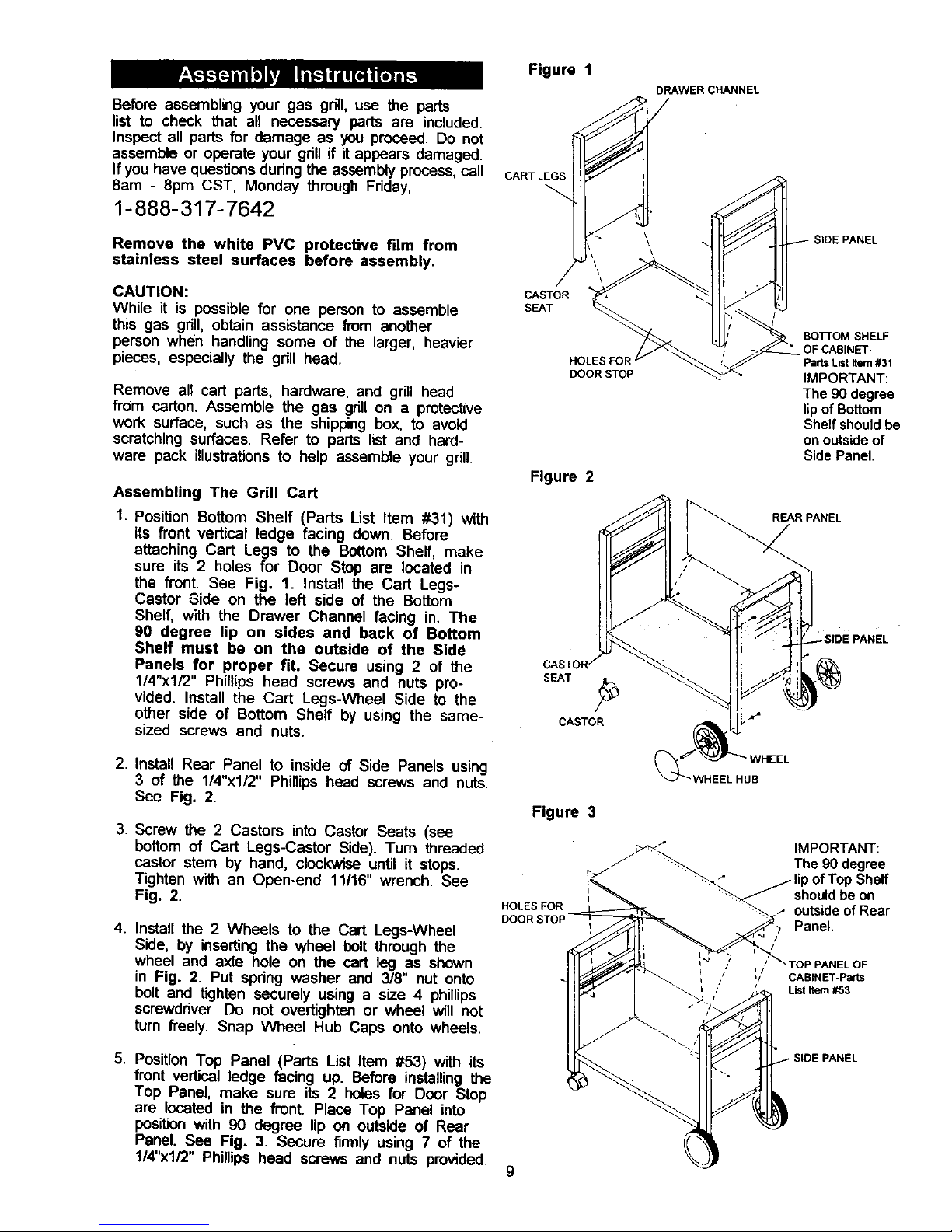
Assembling The Grill Cart
1. Position Bottom Shelf (Parts List Item #31) with
its front vertical ledge facing down. Before
attaching Cart Legs to the Bottom Shelf, make
sure its 2 holes for Door Stop are located in
the front. See Fig. 1. Install the Cart Legs-
Castor Side on the left side of the Bottom
Shelf, with the Drawer Channel facing in. The
90 degree lip on sides and back of Bottom
Shelf must be on the outside of the Side
Panels for proper fit. Secure using 2 of the
1/4"x1/2" Phillips head screws and nuts pro-
vided. Install the Cart Legs-Wheel Side to the
other side of Bottom Shelf by using the same-
sized screws and nuts.
2. InstaU Rear Panel to inside of Side Panels using
3 of the 1/4"x1/2" Phillips head screws and nuts.
See Fig. 2.
3. Screw the 2 Castors into Castor Seats (see
bottom of Cart Legs-Castor Side). Turn threaded
castor stem by hand, clockwise until it stops.
Tighten with an Open-end 11116" wrench. See
Fig. 2.
4. Install the 2 Wheels to the Cart Legs-Wheel
Side, by inserting the wheel bolt through the
wheel and axle hole on the cart leg as shown
in Fig. 2. Put spring washer and 3/8" nut onto
bolt and tighten securely using a size 4 phillips
screwdriver. Do not overtighten or wheel will not
turn freely. Snap Wheel Hub Caps onto wheels.
5. Position Top Panel (Parts List Item #53) with its
front vertical ledge facing up. Before installing the
Top Panel, make sure its 2 holes for Door Stop
are located in the fronL Place Top Panel into
position with 90 degree lip on outside of Rear
Panel. See Fig. 3. Secure firmly using 7 of the
1/4"xl/2" Phillips head screws and nuts provided.
Figure I
/
CASTOR
S_T
HOLE_
DOORSTOP
Figure 2
)RAWER CHANNEL
/
BOTTOM SHELF
OF CABINET-
Parts List Item #31
IMPORTANT:
The 90 degree
lipof Bottom
Shelfshouldbe
on outsideof
Side Pane|.
CASTOR
Figure 3
i
HOLESFOR
DOOR
WHEEL
WHEELHUB
IMPORTANT:
The 90 degree
lip of Top Shelf
should be on
outside of Rear
Panel.
/
/ Lb_TOP PANEL OF
'/ CABINET-Parts
/ List Item #53
SIDE PANEL
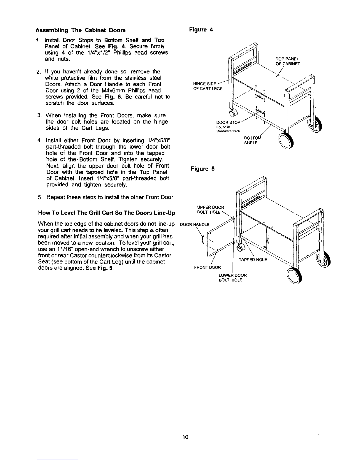
Assembling The Cabinet Doors
1. tnstall Door Stops to Bottom Shelf and Top
Panel of Cabinet. See Fig. 4. Secure firmly
using 4 of the 1/4"x1/2" Phillips head screws
and nuts.
Figure 4
2, If you haven't already done so, remove the
white protective film fi'om the stainless steel
Doors. Attach a Door Handle to each Front
Door using 2 of the M4x6mm Phillips head
screws provided. See Fig. 5. Be careful not to
scratch the door surfaces.
OF CART LEGS
3. When installing the Front Doors, make sure
the door bolt holes are located on the hinge
sides of the Cart Legs.
4. Install either Front Door by inserting 1/4"x5/8"
part-threaded bolt through the lower door bolt
hole of the Front Door and into the tapped
hole of the. Bottom Shelf. Tighten securely.
Next, align the upper door bolt hole of Front
Door with the tapped hole in the Top Panel
of Cabinet. Insert 1!4"x5/8" part-threaded bolt
provided and tighten securely.
Figure 5
BOTTOM
SHELF
5. Repeat these steps to install the other Front Door.
UPPER DOOR
How To Level The Grill Cart So The Doors Line-Up
When the top edge of the cabinet doors do not line-up DOORHANDLE
your grill cart needs to be leveled. This step is often
required after initial assembly and when your grillhas
been moved to a new location. To level your grill cart,
use an 11/16" open-end wrench to unscrew either
front or rear Castor counterclockwise from its Castor
Seat (see bottom of the Cart Leg) until the cabinet
doors are aligned. See Fig. 5.
TAPPED HOLE
FRONT DOOR
LOWER DOOR
BOLT HOLE
TOP PANEL
OF CABINET
10
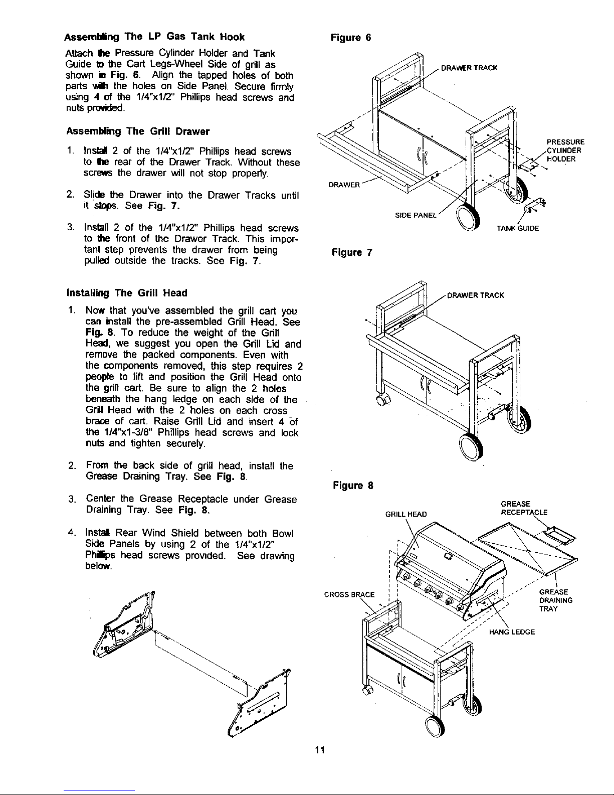
Assembling The LP Gas Tank Hook
Attach Ihe Pressure Cylinder Holder and Tank
Guide to the Cart Legs-Wheal Side of grill as
shown in Fig. 6. Align the tapped holes of both
parts v4h the holes on Side Panel, Secure firmly
using 4 of the 1/4"xl/2" Phillips head screws and
nuts provided,
Assembling The Grill Drawer
1. Install 2 of the 1/4"xl/2" Phillips head screws
to the rear of the Drawer Track. Without these
screws the drawer will not stop properly.
2. Slide the Drawer into the Drawer Tracks until
it st_os. See Fig. 7.
3. Install 2 of the 1/4"x112" Phillips head screws
to the front of the Drawer Track, This impor-
tant step prevents the drawer from being
pulled outside the tracks. See Fig. 7.
Figure 6
Figure 7
SIDE
TANK GUIDE
PRESSURE
HOLDER
Installing The Grill Head
.
Now that you've assembled the grill cart you
can install the pre-assembled Grill Head. See
Fig. 8. To reduce the weight of the Grill
Head, we suggest you open the Gdll Lid and
remove the packed components. Even with
the components removed, this step requires 2
people to lift and position the Grill Head onto
the grill cart. Be sure to align the 2 holes
beneath the hang ledge on each side of the
Grill Head with the 2 holes on each cross
braoe of cart. Raise Grill Lid and insert 4 ()f
the 1/4"xl-3/8" Phillips head screws and lock
nuts and tighten securely.
2. From the back side of grill head, install the
Grease Draining Tray. See Fig, 8.
3. Center the Grease Receptacle under Grease
Draining Tray. See Fig. 8.
.
Install Rear Wind Shield between both Bowl
Side Panels by using 2 of the 1/4"x1/2"
Phillips head screws provided, See drawing
below.
Figure 8
GRILL HEAD
i
CROSS BRACE =
11
GREASE
RECEPTACLE
. _" GREASE
DEAIN_NG
TRAY
HANG LEDGE
 Loading...