

Page 1

OPERATOR'S MANUAL
L I T
Liquid Propane Gas (LPG)Grill
Model141.16677
Natural Gas (NG)Grill
Model141.17677
• Safety
• Assembly
• Use and Care
• Cooking Guide
• Frequently Asked Questions
Call us first if you have any problem with
this product. We can help you with ques-
tions about assembly and grill operation or
if there are damaged or missing parts
when you unpack this unit from the ship-
ping box. Please call before contacting
your local retailer.
1-888-317-7642
8am-8pm CST, Monday throu,qh Friday
• NOTE TO ASSEM BLER/INSTALLER:
Leave this manual with the consumer.
• NOTETO CONSUMER:
Keep this manual for future reference.
• RECORDYOURSERIAL#
(see silver CSA label on main body of grill)
Sears, Roebuck and Co., Hoffman Estates, IL 60179, USA www.sears.com
Failure to comply with these instructions could
result in a fire or explosion that could cause
serious bodily injury, death or property damage.
Whether this grill was assembled by you or
someone else, you must read thisentire manual
before using your grill to ensure the grill is
properly assembled, installed and maintained.
Use your grill at least 3 feet away from any
wall or surface. Use your grill at least 3 feet
away from combustible objects that can melt or
catch fire (such as vinyl or wood siding, fences
and overhangs) or sources of ignition including
pilot lights on water heaters and live electrical
appliances.
THIS GAS APPLIANCE IS DESIGNED FOR
OUTDOOR USE ONLY.
Combustion byproducts produced when using
this product contain chemicals known to the
State of California to cause cancer, birth
defects, or other reproductive harm.
This product contains chemicals known to
the State of California to cause cancer, birth
defects, or other reproductive harm.
Manual # P80106006P - Date:2007/05/22
Page 2
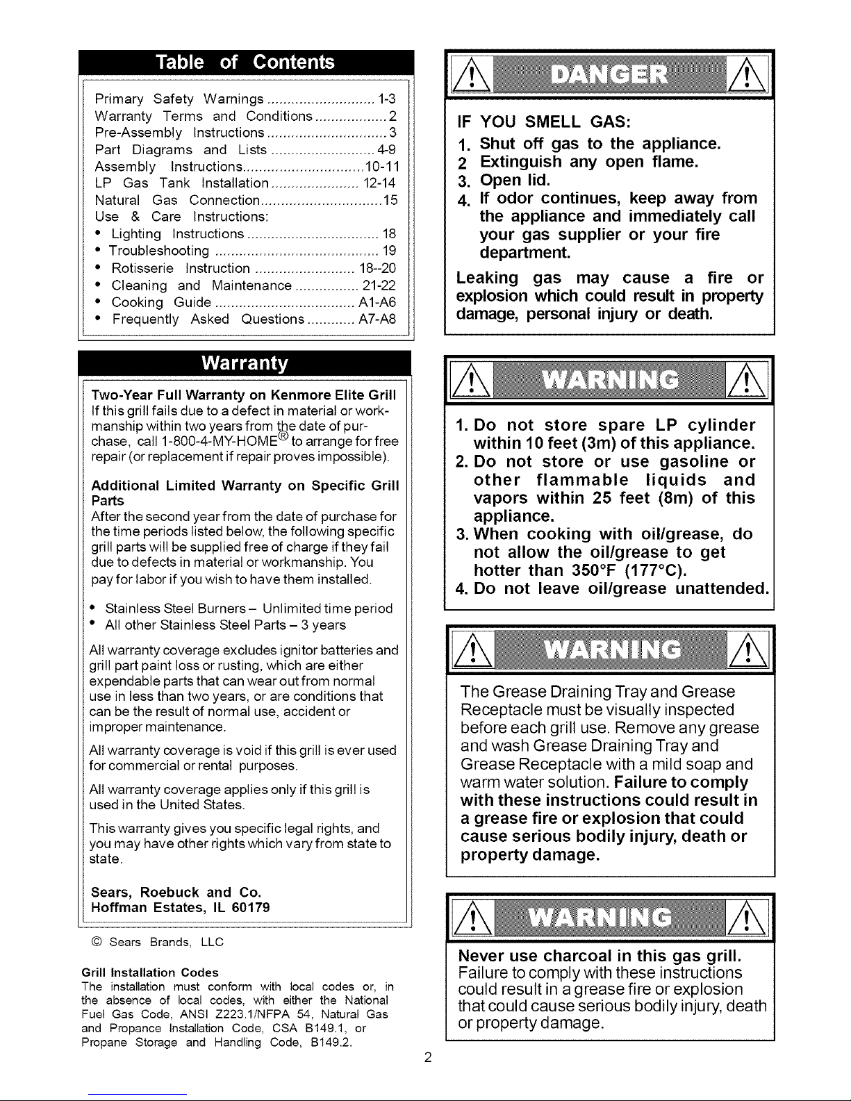
Primary Safety Warnings ........................... 1-3
Warranty Terms and Conditions .................. 2
Pre-Assembly Instructions .............................. 3
Part Diagrams and Lists .......................... 4-9
Assembly Instructions .............................. 10-11
LP Gas Tank Installation ...................... 12-14
Natural Gas Connection .............................. 15
Use & Care Instructions:
• Lighting Instructions ................................. 18
• Troubleshooting ......................................... 19
• Rotisserie Instruction ......................... 18--20
• Cleaning and Maintenance ................ 21-22
• Cooking Guide ................................... A1-A6
• Frequently Asked Questions ............ A7-A8
Two-Year Full Warranty on Kenmore Elite Grill
If this grill fails due to a defect in material or work-
manship within two years from t_e date of pur-
chase, call 1-800-4-MY-HOME "_ to arrange for free
repair (or replacement if repair proves impossible).
Additional Limited Warranty on Specific Grill
Parts
After the second year from the date of purchase for
the time periods listed below, the following specific
grill parts will be supplied free of charge if they fail
due to defects in material or workmanship. You
pay for labor if you wish to have them installed.
• Stainless Steel Burners- Unlimited time period
• All other Stainless Steel Parts - 3 years
IF YOU SMELL GAS:
1. Shut off gas to the appliance.
2 Extinguish any open flame.
3. Open lid.
4. If odor continues, keep away from
the appliance and immediately call
your gas supplier or your fire
department.
Leaking gas may cause a fire or
explosion which could result in property
damage, personal injury or death.
1. Do not store spare LP cylinder
within 10 feet (3m) of this appliance.
2. Do not store or use gasoline or
other flammable liquids and
vapors within 25 feet (8m) of this
appliance.
3. When cooking with oil/grease, do
not allow the oil/grease to get
hotter than 350°F (177°C).
4. Do not leave oil/grease unattended.
All warranty coverage excludes ignitor batteries and
grill part paint loss or rusting, which are either
expendable parts that can wear out from normal
use in less than two years, or are conditions that
can be the result of normal use, accident or
improper maintenance.
All warranty coverage is void if this grill is ever used
for commercial or rental purposes.
All warranty coverage applies only if this grill is
used in the United States.
This warranty gives you specific legal rights, and
you may have other rights which vary from state to
state.
Sears, Roebuck and Co.
Hoffman Estates, IL 60179
© Sears Brands, LLC
Grill Installation Codes
The installation must conform with local codes or, in
the absence of local codes, with either the National
Fuel Gas Code, ANSI Z223.1/NFPA 54, Natural Gas
and Propance installation Code, CSA B149.1, or
Propane Storage and Handling Code, B149.2.
The Grease Draining Tray and Grease
Receptacle must be visually inspected
before each grill use. Remove any grease
and wash Grease Draining Tray and
Grease Receptacle with a mild soap and
warm water solution. Failure to comply
with these instructions could result in
a grease fire or explosion that could
cause serious bodily injury, death or
property damage.
Never use charcoal in this gas grill.
Failure to comply with these instructions
could result in a grease fire or explosion
that could cause serious bodily injury, death
or property damage.
Page 3
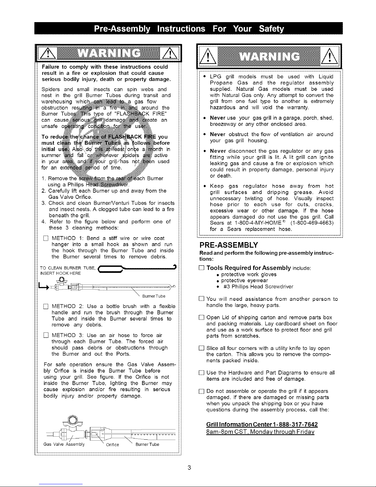
Failure to comply with these instructions could
result in a fire or explosion that could cause
serious bodily injury, death or property damage.
Spiders and small insects can spin webs and
nest in the grill Burner Tubes during transit and
warehousing whi< gas flow
obstruction around the
Burner Tube ,K FIRE"
can an
unsafe
To red_ you
must _efore
initial in
summer active
in your used
for an
1. Remove th_ Burner
using a Phillips
2. Carefully lift each Burner up and away from the
Gas Valve Orifice.
3. Check and clean Burner/Venturi Tubes for insects
and insect nests. A clogged tube can lead to a fire
beneath the grill.
4. Refer to the figure below and perform one of
these 3 cleaning methods:
[] METHOD 1: Bend a stiff wire or wire coat
hanger into a small hook as shown and run
the hook through the Burner Tube and inside
the Burner several times to remove debris.
TO CLEAN BURNER TUBE,_
INSERT HOOK HERE
BureerTube
[] METHOD 2: Use a bottle brush with a flexible
handle and run the brush through the Burner
Tube and inside the Burner several times to
remove any debris.
[] METHOD 3: Use an air hose to force air
through each Burner Tube. The forced air
should pass debris or obstructions through
the Burner and out the Ports.
For safe operation ensure the Gas Valve Assem-
bly Orifice is inside the Burner Tube before
using your grill. See figure. If the Orifice is not
inside the Burner Tube, lighting the Burner may
cause explosion and/or fire resulting in serious
bodily injury and/or property damage.
LPG grill models must be used with Liquid
Propane Gas and the regulator assembly
supplied. Natural Gas models must be used
with Natural Gas only. Any attempt to convert the
grill from one fuel type to another is extremely
hazardous and will void the warranty.
• Never use your gas grill in a garage, porch, shed,
breezeway or any other enclosed area.
• Never obstruct the flow of ventilation air around
your gas grill housing.
Never disconnect the gas regulator or any gas
fitting while your grill is lit. A lit grill can ignite
leaking gas and cause a fire or explosion which
could result in property damage, personal injury
or death.
Keep gas regulator hose away from hot
grill surfaces and dripping grease. Avoid
unnecessary twisting of hose. Visually inspect
hose prior to each use for cuts, cracks,
excessive wear or other damage. If the hose
appears damaged do not use the gas grill. Call
Sears at 1-800-4-MY-HOME _ (1-800-469-4663)
for a Sears replacement hose.
PRE-ASSEMBLY
Read and perform the following pre-assembly instruc-
tions:
[] Tools Required for Assembly include:
• protective work gloves
• protective eyewear
• #3 Phillips Head Screwdriver
[] You will need assistance from another person to
handle the large, heaw parts.
[] Open Lid of shipping carton and remove parts box
and packing materials. Lay cardboard sheet on floor
and use as a work surface to protect floor and grill
parts from scratches.
[] Slice all four corners with a utility knife to lay open
the carton. This allows you to remove the compo-
nents packed inside.
[] Use the Hardware and Part Diagrams to ensure all
items are included and free of damage.
[] Do not assemble or operate the grill if it appears
damaged. If there are damaged or missing parts
when you unpack the shipping box or you have
questions during the assembly process, call the:
Gas Valve AssembIy Orifice BurnerTube
Grill Information Center 1- 888-317-7642
8am-8pm CST, Monday throu,qh Friday
Page 4
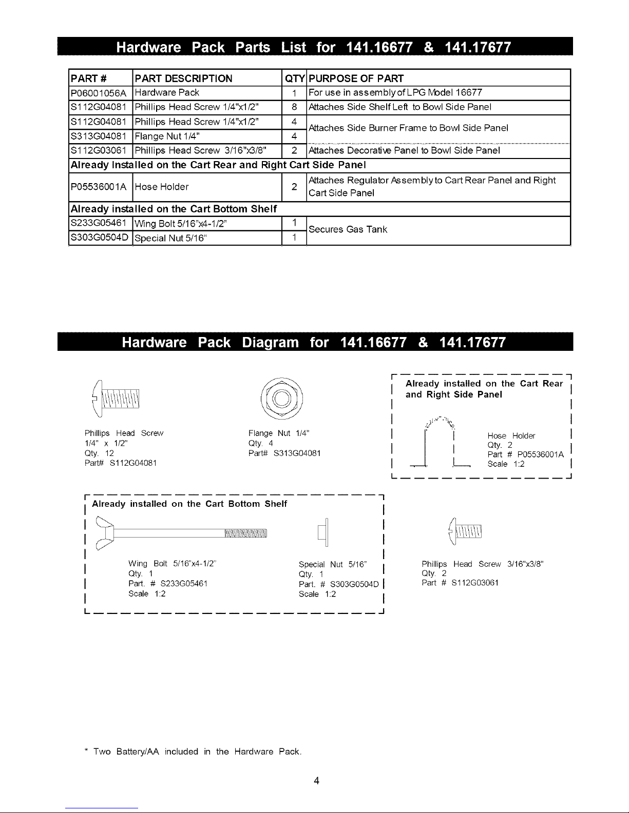
PART #
P06001056A
S112G04081
$112G04081
$313G04081
$112G03061
Already Installed
PART DESCRI PTION
Hardware Pack
Phillips Head Screw 1/4"xl/2"
Phillips Head Screw 1/4"xl/2"
Flange Nut 1/4"
Phillips Head Screw 3/16"x3/8"
on the Cart Rear and Right
QTY PURPOSE OF PART
1 For use in assemblyofLPG Model 16677
8 Attaches Side ShelfLeft to Bowl Side Panel
Attaches Side Burner Frame to Bowl Side Panel
4
2 Attaches Decorative Panel to Bowl Side Panel
Cart Side Panel
P05536001A Hose Holder
Already installed on the Cart Bottom Shelf
$233G05461 Wing Bolt 5/16"x4-1/2"
S303G0504D Special Nut 5/16"
©
Phillips Head Screw Flange Nut 1_"
1_" x 1/2" Qty. 4
Qty. 12 PaR# $3!3G04081
Part# $1!2G04081
2 Attaches RegulatorAssemblyto Cart Rear Panel and Right
Cart Side Panel
1
Secures Gas Tank
1
Already installed on the Cart Rear
and Right Side Panel
,__[ J Hose Holder
I Qty. 2
• .L Scale 1:2
Part # P05536001A
F"
Already installed on the Cart Bottom Shelf
I/!/!/!/!/!/!/!/!/!/!/!/!/!/!1]
Wing Bolt 5/16"x4-1/2"
Qty. 1
Part. # S233G05461
Scale 1:2
* Two Battery/AA included in the Hardware Pack.
Special Nut 5/16"
Qty. 1
Part. # S303G0504D
Scale 1:2
Phillips Head Screw 3/16"x3/8"
Qty. 2
Part # $1!2G03061
Page 5
2
5
1
4
28
33 \
10
80
79
\
13
76
77
24
20_
26
8
12
19 _ BIO
B4_ _
18 \ B2
15 % B9
G
B5__
B1
16
38
69
6
70
Page 6
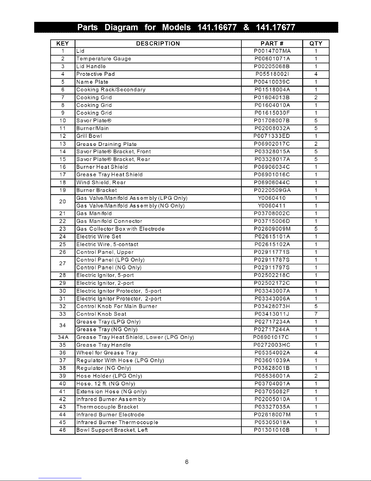
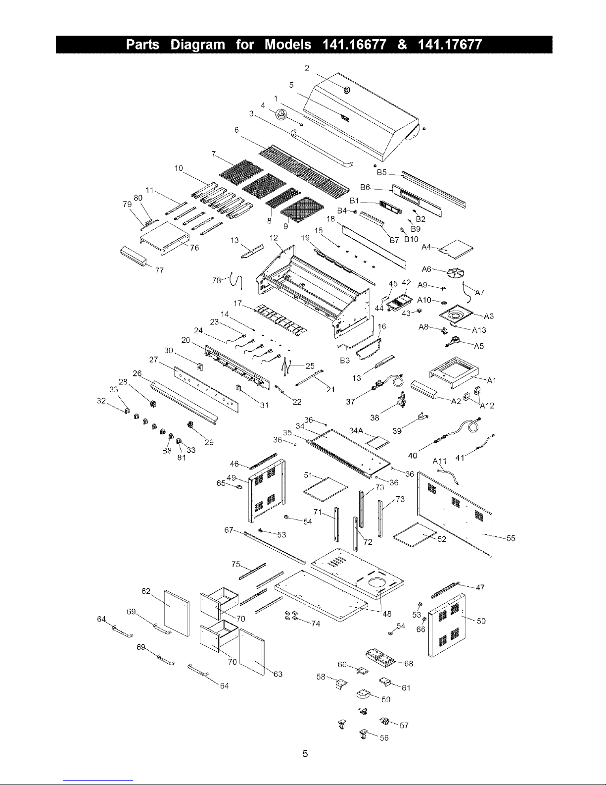
KEY DESCRIPTION PART # QTY
1 Lid P0014707MA 1
2 Temperature Gauge P00601071A 1
3 Lid Handle P00205068B 1
4 Protective Pad P055180021 4
5 Name Plate P00410039C 1
6 Cooking Rack/Secondary P01518004A 1
7 Cooking Grid P01604013B 2
8 Cooking Grid P01604010A 1
9 Cooking Grid P01615030F 1
10 Savor Plate® P01708007B 5
11 Burner/Main P02008032A 5
12 Grill Bowl P0071333ED 1
13 Grease Draining Plate P06902017C 2
14 Savor Plate® Bracket, Front P03328015A 5
15 Savor Plate® Bracket, Rear P03328017A 5
16 BurnerHeatShield P06906034C 1
17 GreaseTrayHeatShield P06901016C 1
18 Wind Shield, Rear P06906044C 1
19 Burner Bracket P0220509GA 1
Gas Valve/Manifold Assembly(LPG Only) Y0060410 1
20
Gas Valve/Manifold Assembly(NG Only) Y0060411 1
21 Gas Manifold P03708002C 1
22 Gas Manifold Connector P03715006D 1
23 Gas Collector Boxwith Electrode P02609009M 5
24 Electric Wire Set P02615101A 1
25 Electric Wire, 5-contact P02615102A 1
26 Control Panel, Upper P02911771S 1
Control Panel (LPG Only) P02911787S 1
27
Control Panel (NG Only) P02911797S 1
28 Electric Ignitor, 5-port P02502218C 1
29 Electric Ignitor, 2-port P02502172C 1
30 Electric Ignitor Protector, 5-port P03343007A 1
31 Electric Ignitor Protector, 2-port P03343006A 1
32 Control Knob For Main Burner P03428073H 5
33 Control Knob Seat P03413011J 7
Grease Tray (LPG Only) P02717234A 1
34
Grease Tray(NG Only) P02717244A 1
34A GreaseTrayHeatShield, Lower (LPG Only) P06901017C 1
35 Grease Tray Handle P0272003HC 1
36 Wheel for Grease Tray P05354002A 4
37 Regulator With Hose (LPG Only) P03601039A 1
38 Regulator (NG Only) P03628001B 1
39 Hose Holder (LPG Only) P05536001A 2
40 Hose, 12 ft. (NG Only) P03704001A 1
41 Extension Hose (NG only) P03705082F 1
42 Infrared Burner Assembly P02005010A 1
43 Therm ocouple Bracket P03327035A 1
44 Infrared Burner Electrode P02618007M 1
45 Infrared Burner Thermocouple P05305018A 1
46 Bowl Support Bracket, Left PO1301010B 1
Page 7

KEY DESCRIPTION PART# QTY
47 BowlSupportBracket,Right P01302010B 1
CartBottomShelf(LPGOnly) PO102OOO2A 1
48
CartBottomShelf(NGOnly) PO102OOO3A 1
49 CartSidePanel,Left P07614010A 1
CartSidePanel,Right(LPGOnly) PO761502OA 1
50
CartSidePanel,Right(NGOnly) PO7615021A 1
51 CartPartitionPanel,Left P07512008N 1
52 CartPartitionPaneI,Right(NGOnly) P07512009N 1
53 CartBottomPanelBracket,LF/RR P03328024C 2
54 CartBottomPanelBracket,RF/LR P03328046C 2
55 CartRearPanel P07701070A 1
56 Caster2-1/2in. P05117010A 2
57 Caster2-1/2in.,withBrake P05110007A 2
58 CasterSeat,LF P05327009Q 1
59 CasterSeat,RF P05327011Q 1
60 CasterSeat,LR P05327010Q 1
61 CasterSeat,RR P05327012Q 1
62 Door,Left PO430204OA 1
63 Door,Right P04303040A 1
64 DoorHandle P00205073B 2
65 DoorHingeBracket,UpperLeft P03314041C 1
66 DoorHingeBracket,UpperRight P03314049C 1
67 CartBracket P03306028A 1
68 Weight P05344004Q 1
69 Handle/Drawer P00212003A 2
70 Drawer Y0420009 2
71 CartPartitionPanelBracket,FrontLeft P019070101 1
72 CartPartitionPanelBracket,FrontRight P01907009B 1
73 CartPartitionPanelBracket,Rear P019070111 2
74 DoorMagnet P05523005M 4
75 DrawerSlideSet P01907006B 4
76 SideShelf,Left P01106009B 1
77 DecorativePanelforSideShelf P07503007A 1
78 LightingStick P05507031E 1
79 ToolHolder P05209004B 1
80 TooIHooks PO5514131F 4
81 ControlKnobForInfraredBurner P03428073H 1
A1 SideBurnerFrame P01108013B 1
A2 DecorativePanelforSideBurnerFrame P07502017A 1
A3 SideBurnerBody P02301019B 1
A4 SideBurnerLid P01127007B 1
SideBurnerwithBrassRing(LPOnly) P02002007A 1
A5
SideBurnerwithBrassRing(NGOnly) P02002014A 1
A6 SideBurnerPotSupport P00805010A 1
A7 SideBurnerElectrode P02614014C 1
A8 SideBurnerGasValve Y0060399 1
A9 SideBurnerControIKnob P03401013H 1
A10 SideBurnerControlKnobSeat P03408053S 1
A11 SideBurnerConnectionHose,Plug P037050511 1
A12 SideBurnerConnectionHose,Bracket P03341001C 2
A13 SideBurnerBracket P03327037C 1
Page 8
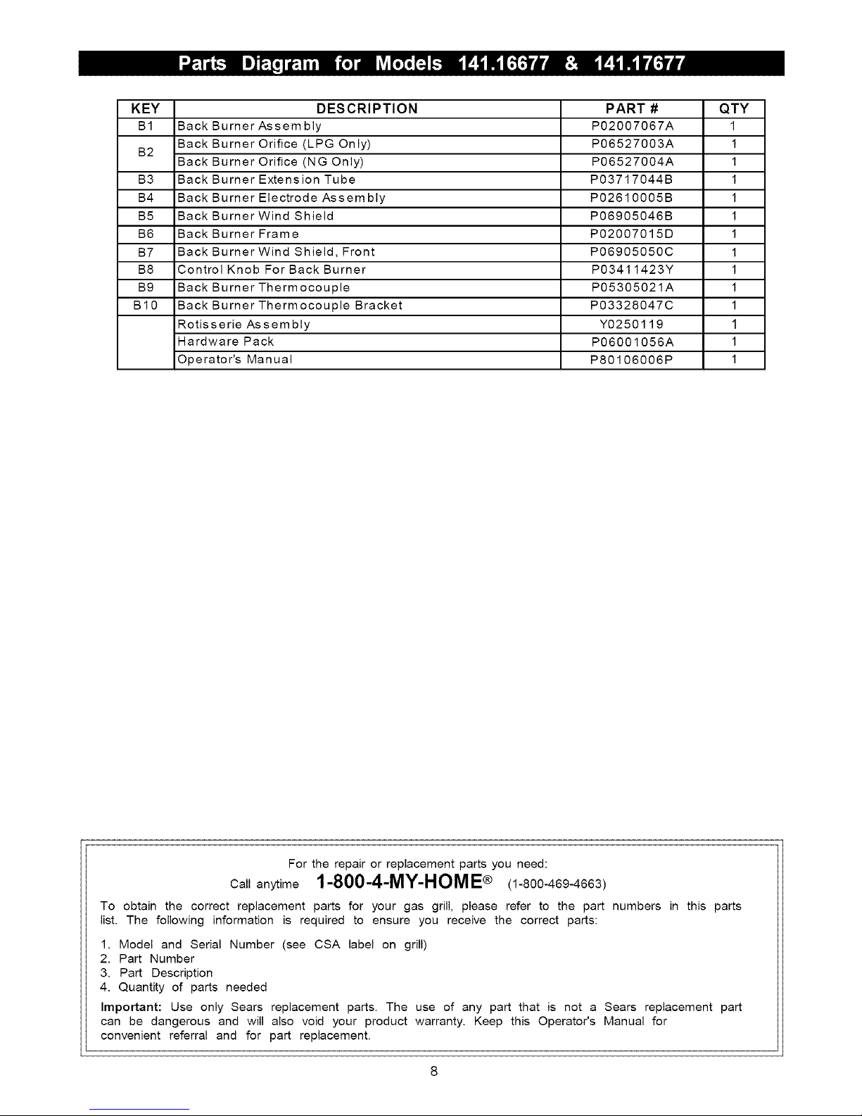
KEY DESCRIPTION PART# QTY
B1 BackBurnerAssembly P02007067A 1
BackBurnerOrifice(LPGOnly) P06527003A 1
B2
BackBurnerOrifice(NGOnly) P06527004A 1
B3 BackBurnerExtensionTube P03717044B 1
B4 BackBurnerElectrodeAssembly P02610005B 1
B5 BackBurnerWindShield P06905046B 1
B6 BackBurnerFrame P02007015D 1
B7 BackBurnerWindShield,Front P06905050C 1
B8 ControlKnobForBackBurner P03411423Y 1
B9 BackBurnerThermocouple P05305021A 1
B10 BackBurnerThermocoupleBracket P03328047C 1
RotisserieAssembly Y0250119 1
HardwarePack P06001056A 1
Operator'sManual P80106006P 1
Fortherepairorreplacementpartsyouneed:
anytime1-800-4-MY-HOME® (1-800-469-4663)
To obtain the correct replacement parts for your gas grill, please refer to the part numbers in this parts
list. The following information is required to ensure you receive the correct parts:
1. Model and Serial Number (see CSA label on grill)
2. Part Number
3. Part Description
4. Quantity of parts needed
Important: Use only Sears replacement parts. The use of any part that is not a Sears replacement part
can be dangerous and will also void your product warranty. Keep this Operator's Manual for
convenient referral and for part replacement.
Page 9
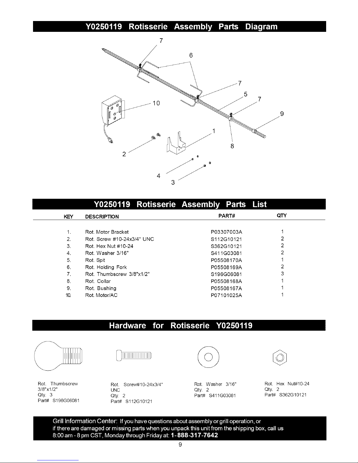
7
6
5
7
3
KEY DESCRIPTION
1. Rot. Motor Bracket
2. Rot. Screw #10-24x3/4" UNC
3. Rot. Hex Nut #10-24
4. Rot. Washer 3/16"
5. Rot. Spit
6. Rot. Holding Fork
7. Rot. Thumbscrew 3/8"x1/2"
8. Rot. Collar
9. Rot. Bushing
10. Rot. Motor/AC
Rot. Thumbscrew
3/8"xl/2"
Qty. 3
Part# $196G06081
_IIIIIIIIIIIIIIIIII]
Rot. Screw#10-24x3/4"
UNC
Qty. 2
Part# $1!2G10121
PART# QTY
P03307003A
S112G10121
S362G10121
S411G03081
P05508170A
P05508169A
S196G06081
P05508168A
P05508167A
P07101025A
©
Rot. Washer 3/16"
Qty. 2
Part# $411G03081
1
2
2
2
1
2
3
1
1
1
Rot. Hex Nut#10-24
Qty. 2
Part# S362G10121
Page 10
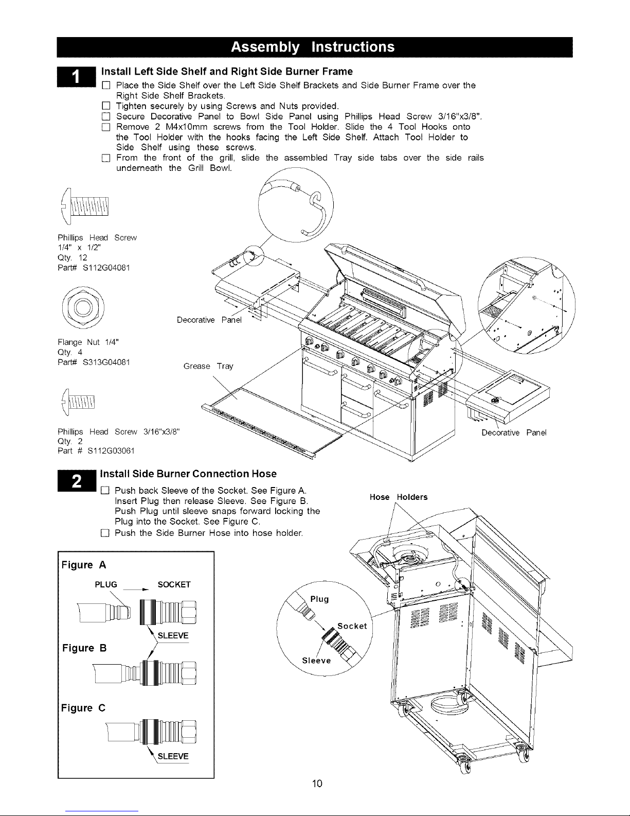
Install Left Side Shelf and Right Side Burner Frame
[] Place the Side Shelf over the Left Side Shelf Brackets and Side Burner Frame over the
Right Side Shelf Brackets.
[] Tighten securely by using Screws and Nuts provided.
[] Secure Decorative Panel to Bowl Side Panel using Phillips Head Screw 3/16"x3/8".
[] Remove 2 M4xl0mm screws from the Tool Holder. Slide the 4 Tool Hooks onto
the Tool Holder with the hooks facing the Left Side Shelf. Attach Tool Holder to
Side Shelf using these screws.
[] From the front of the grill, slide the assembled Tray side tabs over the side rails
underneath the Grill Bowl.
Phillips Head Screw
1/4" x 1/2"
Qty. 12
Part# $112G04081
©
Flange Nut 1/4"
Qty. 4
Part# $3!3G04081
Phillips Head Screw 3/16"x3/8"
Qty. 2
Part # $1!2G03061
Install Side Burner Connection Hose
[] Push back Sleeve of the Socket. See Figure A.
insert Plug then release Sleeve. See Figure B.
Push Plug until sleeve snaps forward locking the
Plug into the Socket. See Figure C.
[] Push the Side Burner Hose into hose holder.
Figure A
PLUG
SOCKET
Decorative Panel
Grease Tray
\
Decorative Panel
Hose Holders
Plug
Figure B
SLEEVE
Figure C
_\SLEEVE
10
Page 11

Install Ignitor Batteries
[] Unscrew Ignitor Cap from Control Panel.
[] Place supplied AA batteries into the
ignitor Slots with positive pole facing
you.
[] Position the Caps and Springs over the
AA batteries and tighten onto Control
Panel.
Main Burners Electrode Check
Perform this Electrode Check with the
assistance of another person.
This test will ensure that the Spark Electrode Tips
are properly positioned so your grill lights easily
and properly.
Spring
Spark Receiver Spark Eiectrode Tip
[] Be sure all Control Knobs are set to
"OFF" and open the Grill Lid.
[] Have your assistant stand behind to the
right of the grill and look toward the front
of the grill bowl. Never put your face
inside the Grill Bowl.
[] Press the Ignitor Cap. You should hear
a "clicking" sound. Your assistant should
see a blue spark within each Gas
Collector Box. If a spark is present the
Electrode Tips are properly positioned.
[] If no spark is seen, the Spark Gap
needs to be adjusted as follows:
• Using an adjustable wrench, loosen the
inside Nut until the Gas Collector Box can
be turned upward.
• If the gap between the Spark Elec-
trode Tip and Receiver is more than
3/16" use long nose pliers to gently
squeeze the Gas Collector Box to
narrow gap.
• Return the Gas Collector Box to its
original position, secure the inside Nut
and try the Electrode Check again. If no
"clicking" sound is heard:
• AA Batteries may be installed back-
wards.
• Electric wires may be loose. Remove
the AA Batteries and inspect the
ignitor Junction Box found behind the
Control Panel and reconnect any
loose wires.
Side Burner Electrode Check
[] Open side burner lid. Remove plastic
shipping band from burner and pot
support.
[] Push and turn side burner Control Knob
to HIGH. Look for spark between tip of
electrode and burner.
[] If you don't see a spark from side burner elec-
trode, adjust gap between electrode and
burner surface to 3/16 in.
H nstall Cooking Components
Secondary Cooking
Cookir
Slots for
Secondary
Cooking Rack
[] Place the Savor Plates ® on lower ledge
above Burners.
[] Place Cooking Grids on bowl ledge.
[] Place the Secondary Cooking Rack into
the slots on Grill Bowl Side Panels
Savor Plates ®
When you have finished assembling your
grill be sure that all screws are tightened
for safe operation of your grill.
Failure to read and follow the Use and Care
Instructions could result in a fire or explosion
that could cause serious bodily injury, death or
property damage.
11
Page 12

CORRECT LP GAS TANK USE
[] LP Gas grill models are designed for use with a
standard 20 lb. Liquid Propane Gas (LP Gas) tank,
not included with gdll. Never connect your gas grill to
an LP Gas tank that exceeds this capacity. A tank of
approximately 12 inches in diameter by 18-1/2 inches
high is the maximum size LP Gas tank to use. You
must use an "OPD" gas tank which offers a listed
Overfill Prevention Device. This safety feature
prevents tank from being overfilled which can cause
malfunction of LP Gas tank, regulator and/or grill.
[] The LP Gas tank must be constructed and marked in
accordance with the Specifications for LP-Gas Cylin-
ders of the U.S. Department of Transportation (D.O.T.)
or the National Standard of Canada, CAN/CSA-B339,
Cylinders, Spheres and Tubes for Transportation of
Dangerous Goods; and Commission, as applicable.
[] The LP Gas tank must have a shutoff valve, terminat-
ing in an LP Gas supply tank valve outlet, that is
compatible with a Type 1 tank connection device. The
LP Gas tank must also have a safety relief device
that has a direct connection with the vapor space of
the tank.
[] The tank supply system must be arranged for vapor
withdrawal.
[] Use of alcohol or drugs may impair the ability to
assemble and operate the appliance.
[] Keep fire extinguisher readily accessible. In the
event of a oil/grease fire, do not attempt to
extinguish with water. Use type B extinguisher
or smother with dirt, sand or baking soda.
[] In the event of rain, cover the grill and turn off
the burner and gas supply.
[] Use your grill on a level, stable surface in an
area clear of combustible materials.
[] Do not leave grill unattended when in use.
[] Do not move the appliance when in use.
[] Allow the grill to cool before moving or storing.
[] Do not use your grill as a heater.
[] This grill is not intended to be installed in or on
recreational vehicles and/or boats.
[] Never use charcoal in this gas grill.
[] The LP Gas tank used must have a collar
to protect the tank valve.
[] Never connect an unregulated LP gas tank to your
gas grill. The gas regulator assembly supplied with
your gas grill is adjusted to have an outlet pressure
of 11" water column (W.C.) for connection to an LP
gas tank. Only use the regulator and hose assembly
supplied with your gas grill. Replacement regulators
and hose assemblies must be those specified by
Sears. See Parts List.
[] Have your LP Gas dealer check the release valve
after every filling to ensure it remains free of defects.
[] Always keep LP Gas tank in upright position.
[] Do not subject the LP Gas tank to excessive heat.
[] Never store an LP Gas tank indoors. If you store
your gas grill in the garage always disconnect the
LP Gas tank first and store it safely outside.
[] LP Gas tanks must be stored outdoors in a well-
ventilated area and out of the reach of children.
[] Disconnected LP Gas tanks must not be stored in a
building, garage or any other enclosed area.
[] The regulator and hose assembly can be seen after
opening the doors (if applicable) and must be
inspected before each use of the grill. If there is
excessive abrasion or wear or if the hose is cut, it
must be replaced prior to using the grill again.
[] Never light your gas grill with the lid closed or
before checking to ensure the burner tubes are fully
seated over the gas valve orifices.
[] Never allow children to operate your grill. Do not
allow children or pets to play near your grill.
A. Do not store a spare LP-Gas tank under or near
this appliance.
B. Never fill the tank beyond 80 percent full; and
C. If the information in "(a)" and "(b)" is not followed
exactly, a fire causing death or serious injury may
occur.
• Use your grill at least 3 feet away from any
wall or surface. Use your grill at least 3 feet
away from combustible objects that can melt
or catch fire (such as vinyl or wood siding,
fences and overhangs) or sources of ignition
including pilot lights on water heaters and live
electrical appliances.
• Outdoor cooking gas appliance shall not be
used under overhead combustible construction.
• Never use your gas grill in a garage, porch, shed,
breezeway or any other enclosed area.
• Never obstruct the flow of ventilation air around
your gas grill housing.
12
Page 13

NOTE about LP Gas Tank Exchange Programs
• Many retailers that sell grills offer you the option of
replacing your empty LP Gas tank through an ex-
change service. Use only those reputable exchange
companies that inspect, precision fill, test and certify
their tanks. Exchange your tank only for an OPD safety
feature-equipped tank as described in the LP Gas tank
section of this manual.
• Always keep new and exchanged LP Gas tanks in an
upright position during use, transit or storage.
• Leak test new and exchanged LP Gas tanks BEFORE
connecting one to your grill.
How to Leak Test your LP Gas Tank
For your safety:
• All leak tests must be repeated each time your LP
Gas tank is exchanged or refilled.
• When checking for gas leaks do not smoke.
• Do not use an open flame to check for gas leaks.
• Your grill must be leak tested outdoors in a well-
ventilated area, away from ignition sources such as
gas fired or electrical appliances. During the leak test,
keep your grill away from open flames or sparks.
• Do not use household cleaning agents. Damage to
gas assembly components can result.
To Install LP Gas Tank (LPG model only):
Secure a 201b LP Gas Tank to Gas Grill
[] Screw the Wing Bolt and Special Nut to Cart
Bottom Shelf.
[] Turn your LP Gas Tank Valve clockwise to the
closed or OFF positon.
[] Place LP Gas tank into tank hole on bottom shelf
or (on select models) slide the Tank Tray out of
the cabinet until it is fully extended. The Tank Tray
has an auto lock position and may need to be
pulled firmly.
[] install the tank so the Tank Valve faces the front
right corner of cabinet.
[] Secure Gas Tank with Special Nut and Wing Bolt.
[] Use a clean paintbrush and a 50/50 mild soap and
water solution.
[] Brush soapy solution onto LP Gas tank in the
areas indicated by the arrows. See diagram.
[] If growing bubbles appear do not use or move the
LP Gas tank. Call an LP Gas Supplier or your Fire
Department.
4-
The Special Nut has
to be mounted to the
Wing Bolt BEFORE
inserting tank into
tank hole.
With the Special Nut,
the Wing Bolt holds
the tank foot firmly.
[I!t!t//!Iflt/t/!N///!/!/!/!/A
Special Nut 5/16" Wing Bolt 5/16"x4-1/2"
Qty. 1 Qty. 1
Part. # S303GO504D Part. # $233G05461
Scale 1:2 Scale 1:2
If growing bubbles appear do not use or move
the LP Gas tank. Contact an LP Gas Supplier
or your fire department!
NOTE: Many different size propane gas tank bottom
collars are available in the market, especially with the
popularity of tank exchange programs, tf your tank
bottom collar does not fit into the tank hole after attaching
the special nut to the wing bolt, simply remove the special
nut and secure the tank using the wing bolt only.
13
Page 14

LP Gas Model only:
Connect Regulator with Hose to your LP Gas Tank
[] Turn all Burner Valves to the OFF position.
[] Inspect the valve connection port and regulator
assembly for damage or debris. Remove any
debris. Never use damaged or plugged equip-
ment.
[] Connect the regulator assembly to the tank valve
and HAND TIGHTEN nut clockwise to a full stop.
DO NOT use a wrench to tighten because it could
damage the Quick Coupling Nut and result in a
hazardous condition.
[] Open the tank valve 1/4 to 1/2 (counterclockwise)
and use a soapy water solution to check all
connections for leaks before attempting to light
your grill. See "Checking for LP Gas Leaks". If
a leak is found, turn the tank valve off and do not
use your grill until the leak is repaired.
TyPsl 12_n5zatt_°coZer
Quick
Coupling Nut
Check all connections for LP Gas Leaks
Never test for leaks with a flame. Prior to first use,
at the beginning of each season, or every time
your LP Gas tank is changed, you must check for
gas leaks. Follow these three steps:
[] Make a soap solution by mixing one part liquid
detergent and one part water.
[] Turn the grill Control Knobs to the full OFF
position, then turn the gas ON at source.
[] Apply the soap solution to all gas connections
indicated by the arrows. See diagram. If
bubbles appear in the soap solution the
connections are not properly sealed. Check
each fitting and tighten or repair as necessary.
Manifold Assembly
CAUTION: When the appliance is not in use the gas
must be turned off at the tank.
I
I
LP Gas Tank
If you have a gas leak that cannot be repaired
by tightening, turn off the gas at the source,
disconnect fuel line from your grill and call
1-800-4-MY-HOME ° or your gas supplier for
repair assistance.
Disconnecting A Liquid Propane Gas (LPG)
Tank From Your Grill
[] Make sure the Burner Valves and LP Gas tank
valve are off. (Turn clockwise to close.)
[] Detach the hose and regulator assembly from
the LP Gas tank valve by turning the Quick
Coupling Nut counterclockwise.
14
Page 15

Natural Gas Model only:
Connecting Natural Gas To Your Grill
[] Connect the Swivel nut of the 12' Natural Gas
Hose to the vertical fitting of NG Regulator as
shown in Fig. 1. Connect the other hose end
(male plug) to the gas supply line from house.
Also, read and follow all natural gas safety
instructions below.
Natural Gas Safety Instructions
[] Your natural gas grill is designed to operate on
natural gas only, at a pressure of 4" water column
(W.C.) with natural gas regulator. The gas pres-
sure Regulator supplied with this appliance must
be used. This Regulator is set for an outlet
pressure of 4" W.C.
[] Install a Shutoff Valve at the gas supply source
outdoors at a point after the gas pipe exits the
outside wall and before the quick-disconnect
hose. Or install it at the point before the gas line
piping enters the ground. See Fig. 2.
[] Pipe sealing compound or pipe thread tape
resistant to the action of natural gas must be used
on all male pipe thread connections.
[] Disconnect your gas grill from fuel source when
the gas supply is being tested at high pressures.
This gas grill and its individual shutoff valve must
be disconnected from the gas supply pipe system
during any pressure testing of that system at
pressure in excess of 1/2 psi (3.5kpa).
[] Turn off your gas grill when the gas supply is
being tested at low pressures. The grill must be
isolated from the gas supply pipe system by
closing its individual manual shutoff valve during
any pressure testing of the gas supply pipe
system at pressures equal to or less than 1/2 psi
(3.5kpa).
Figure 1 S
Vertical fitting _ _ __
Swwel nut _
Check all connections for NG Leaks
Never test for leaks with a flame. Prior to first use,
at the beginning of each season, you must check
for gas leaks. Follow these three steps:
[] Make a soap solution by mixing one part liquid
detergent and one part water.
[] Turn the grill Control Knobs to the full OFF
position, then turn the gas ON at source.
[] Apply the soap solution to all gas connections
indicated by the arrows. See Fig. 3. If bubbles
appear in the soap solution the connections are
not properly sealed. Check each fitting and
tighten or repair as necessary.
Figure 3
Gas Valve / Manifold Assembly
/
Figure 2
Inside Wall
Outside Wall
Male Fitting
Gas
Shut Off
Locking
Shut Off
Quick
Disconnect
NG Regulator J
Hose, 12 ft./NG
If you have a gas leak that cannot be repaired
by tightening, turn off the gas at the source,
disconnect fuel line from your grill and call
1-800-4-MY-HOME ® or your gas supplier for
repair assistance.
15
Page 16

Grill Lighting Instructions
1. Before each use, check all hoses for cracks, nicks, cuts,
burns or abrasions, if a hose is damaged in any way, do
not use your grill before replacing the hose with an
authorized part from the Parts List. Also make sure all
gas supply connections are securely tightened.
2. Familiarize yourself with the safety and Use and Care
instructions in this manual. Do not smoke while lighting
grill or checking gas supply connections.
3. Be sure the LP Gas tank is filled.
4. Open the Grill Lid.
5. Check that the end of each Burner Tube is properly
located over each Valve Orifice.
Failure to replace a faulty hose, secure gas supply
connections or to open the Lid before proceeding
to the Lighting Procedures could result in a fire
or explosion that could cause serious bodily injury,
death, or property damage.
6. Set Control Knobs to OFF and open the LP Gas
tank valve SLOWLY 1/4 of a turn. For Natural Gas
open the Shut Off Valve at source.
| Open LP Gas tank _-"_
OFF
7. Push and turn one Control Knob to IGN and hold it in
3-4 secs to ignite the Burner._Once the burner is lit,
turn the knob back to HIGH,
!
IGN
Low_
OFF
8. If ignition does not occur in 5 seconds, turn gas off at
source and turn Control Knobs OFF. Wait at least 5
minutes for gas to clear, then retry. If your grill still fails
to light turn the burner Control Knob(s) and gas source
OFF and conduct a leak test of ALL gas connections
and gas sources as explained in the Use and Care
section of this manual, if no leaks are detected, wait 5
minutes for any gas to clear and repeat the lighting
procedure.
9. After one Burner is lit, turn the tank valve SLOWLY one
more 1/4 of a turn for 1/2 of one complete turn.
10. Repeat steps to light each burner individually. Turn
Knob for each other burner and light as you move
toward the fuel source.
Burner Control Knobs on Control Panel
Main Burner Back Infrared
Burner Burner
Back Burner Lighting Instructions
1. Follow steps 1 through 6 of the Grill Lighting
instructions.
2. Push and turn the Control Knob to IGN and hold it in
3-4 seconds to ignite the Burner.
3. Keep pressing and turning knob to HIGH and hold in
5-10 seconds before releasing.
4. if ignition does not occur in 5 seconds, turn gas off
at source and turn Control Knobs OFF. Wait at least
5 minutes for gas to clear, then retry. If your grill still
fails to light turn the Control Knob(s) and gas
source OFF and conduct a leak test as explained in
the Use and Care section of this manual. If no
leaks are detected, wait 5 minutes for any gas to
clear and repeat the lighting procedure.
5. After Burner is lit, turn the tank valve SLOWLY one
more 1/4 of a turn for 1/2 of one complete turn.
IMPORTANT: Do not use the Back Burner and Main
Burners at the same time. Backburner is for Rotisserie
Cooking only.
BACK BURNER KNOB:
!
IGN
OFF
Infrared Burner Lighting
1.
Follow steps 1 through 6 of the Grill Lighting
instructions.
2.
Push and turn the Control Knob to IGN and hold it in
3-4 secs to ignite the Burner.
3.
Keep pressing and turning knob to HIGH and hold in
5-10 seconds before releasing.
4.
if ignition does not occur in 5 seconds, turn the
burner Control Knob(s) and gas source OFF and
conduct a leak test as explained in the Use and
Care section of this manual. If no leaks are de-
tected, wait 5 minutes for any gas to clear and
repeat the lighting procedure.
5. After Burner is lit, turn the tank valve SLOWLY one
more 1/4 of a turn for 1/2 of one complete turn.
Side Burner Lighting Instructions
1. Follow steps 1 through 5 of the Grill Lighting
Instructions.
2. Open Side Burner Lid.
3. Set Control Knobs to OFF and open the LP Gas
tank valve SLOWLY 1/4 of a turn.
4. Push and turn control knob to HIGH ._
5. You may have to push and turn the Control Knob up
to 3 or 4 times to light.
6. If ignition does not occur, turn gas off at source and
turn Control Knobs OFF. Wait at least 5 minutes for
gas to clear, then retry, if your grill still fails to light turn
the burner Control Knob and gas source OFF and
conduct a leak test of ALL gas connections and fuel
sources. If no leaks are detected, wait 5 minutes for
any gas to clear and repeat the lighting procedure.
INFRARED BURNER
KNOB: |
IGN
Low_
OFF
Instructions
Manually Lighting Your Grill By Paper Match
To light your gas grill by match, insert a match into the
Lighting Stick and follow steps 1 through 6 of the Grill
Lighting Instructions. Then, light the match and place
(continue over page)
16
Page 17

LightingStickthroughtheLightingHoleontheleftside
ofthegrillasshownbelow.TurnthenearestControl
KnobtotheHIGHsettingtoreleasegas.TheBurner
shouldlightimmediately.
LightingH_
Lighting
Troubleshooting
If the grill fails to light :
Turn gas off at source and turn Control Knobs to
OFF. Wait at least 5 minutes for gas to clear, then
retry.
2.
If your grill still fails to light, check gas supply
and connections.
3.
Repeat lighting procedure. If your grill still fails
to operate, turn the gas off at source, turn the
Control Knobs to OFF, then check the following:
[]
Misalignment of Burner Tubes over Orifices
Correction: Reposition Burner Tubes over Orifices.
[]
Obstruction in gas line
Correction: Remove fuel line from grill. Do not
smoke! Open gas supply for one second to clear
any obstruction from fuel line. Close off gas supply
at source and reconnect fuel line to grill.
[]
Plugged Orifice
Correction: Remove Burners from grill by remov-
ing the screw from the rear of each Burner using a
Phillips Head Screwdriver. Carefully lift each
Burner up and away from gas valve Orifice.
Remove the Orifice from gas valve and gently clear
any obstruction with a fine wire. Then reinstall all
Orifices, Burners and cooking components.
If an obstruction is suspected in Gas Valves or
Manifold, call the Grill Information Center.
Obstruction in Burner Tubes
[]
Correction: Follow the Burner Tube cleaning
procedure on page 22 of this Operator's Manual.
[]
Misalignment of Ignitor on Burner
Correction: Check for proper position of the
Electrode Tip as shown in step 4 page 11. The
gap between the Spark Electrode Tip and Spark
Receiver should be approximately 3/16". Adjust
if necessary. With the gas supply closed and all
Control Knobs set to OFF press the Electric
Ignitor cap and check for the presence of a spark
at the Electrode.
Match
Disconnected Electric Wires
[]
Correction: inspect the Electric ignitor (see Parts
List) found behind the Control Panel. Connect loose
Electric wires to Junction Box and try to light the grill.
[]
Weak AA battery
Correction: Unscrew the Ignitor Cap and replace
the battery.
[]
If the grill still does not light you may need to
purge air from the gas line or reset the
regulator excess gas flow device. Note: This
procedure should be done every time a new
LP Gas tank is connected to your grill.
To purge air from your gas line and/or reset
the regulator excess gas flow device:
[] Turn Control Knobs to the OFF position.
[] Turn off the gas at the tank valve.
For Natural Gas shut off NG valve.
[] Disconnect regulator from LP Gas tank.
For Natural Gas disconnect regulator from 12 ft.
Natural Gas Hose.
[]
Let unit stand 5 minutes to allow air to purge
from gas line.
[]
Reconnect regulator to the LP Gas tank.
For Natural Gas reconnect regulator to 12 ft.
Natural Gas Hose.
[] Turn tank valve on SLOWLY 1/4 of a turn.
For Natural Gas open Shut Off valve.
[] Open the Grill Lid.
[] Push and turn the LEFT Control Knob to HIGH.
[] Press Electric ignitor for 3-4 seconds to light
the burners.
Should a FLASHBACK fire occur in or around
the Burner Tubes, follow the instructions below.
Failure to comply with these instructions could
result in a fire or explosion that could cause
serious bodily injury, death, or property damage.
• Shut off gas supply to the gas grill.
• Turn the Control Knobs to OFF position.
• Open the Grill Lid.
• Put out any flame with a Class B fire
extinguisher.
• Once the grill has cooled down, clean
the Burner Tubes and Burners according
to the cleaning instructions in this
Operator's Manual.
Call 8am to 8pm CST 1-888-317-7642 Monday through Friday
GRILL INFORMATION CENTER
17
Page 18

Never lean over the grill cooking area while
lighting your gas grill. Keep your face and body
a safe distance (at least 18 inches) from the
Lighting Hole or Burners when lighting your grill
by match.
CORRECT ROTISSERIE USE
1. Read all instructions before initial use.
IMPORTANT: When using electrical appliances, basic
safety precautions should always be used.
The Rotisserie Motor is set for 120V, 60Hz AC current.
The Rotisserie is for outdoor use only.
Do not let children operate or play nearby your grill or
Rotisserie.
Connecting Rotisserie
2. Always attach the assembled Rotisserie to your grill first
and then plug the Cord into an outlet.
Operating Rotisserie
3. Do not operate the Rotisserie if the cord or plug be-
comes damaged, or if the Rotisserie malfunctions or
has been damaged in any manner.
Keep any electrical supply cord and the fuel
supply hose away from any heated surface.
The use of accessory attachments is not recommeded
by the manufacturer and may cause injuries. Do not use
this Rotisserie other than for its intended use.
Do not immerse Electrical Cord, Plug or Motor in water
or expose to rain, as this may result in an electrical
shock.
Disconnect Rotisserie
Be careful as all surfaces will be hot, both grill and
Rotisserie parts. Use protective mitts to handle the
Rotisserie.
Unplug the Rotisserie from electrical outlet when not in
use and before cleaning. Allow to cool before adding or
removing parts.
When Roitsserie cooking place a Cooking Pan under
the food to be cooked as this will capture the drippings
and keep your grill clean of excess grease which could
cause a fire.
CAUTION: Handle with care when moving a Cooking
Pan with hot oils
Should a grease fire occur, turn the burners and gas off
and leave the grill lid Closed until the fire is out.
Store the Rotisserie indoors
5. When Rotisserie is not in use, store it indoors in a dry
place.
18
Page 19

.
Remove all components from the carton.
2.
Attach the Motor Bracket on the outside of the left grill bowl panel. Align the two holes of the Bracket
with the holes on the grill bowl. Tighten securely using two Screws #10-24x3/4" UNC, Plain Washers
and Nuts provided.
Washer
[ 111111111111111111/
Rot. Screw #10-24x3/4" UNC x2
©
Rot. Washer x2
Motor Bracket ._
#10-24 Nut
Rot. Screw#10-24x3/4"
Rot. Nut #10-24 x2
.
Slide the Spit through the piece of meat or poultry and the Holding Forks onto each end of the Rotisserie
UNC with washers
and nuts
/(_, J'f'J
Outside of left grill
bowl panel
Spit. Adjust spacing between Holding Forks to accommodate your food, then tighten the Thumbscrews
to keep the Holding Forks in position. Slide the Collar and Bushing onto the threaded end of the Spit.
Do not tighten the Collar Thumbscrew until the Rotisserie is placed into your grill.
Thumbscrew
3/8"xl/2"
Rot.Thumbscrew 3/8"xl/2" x3
Holding Forks
Spit
Bushing
Collar
Thumbscrew
3/8"x1/2"
19
Page 20

4. InstalltheAC(alternatingcurrent)RotisserieMotorontothe MotorBracketasshownbelow.Besure
theMotorattachesto the Bracketwiththe electricalcorddown.This installationinsuresthatonce
the Spit is insertedinto the Motorit will alsorestsecurelyintotheslotof yourgrillbowl.
Rotisserie Motor
Motor Bracket
Rotisserie Spit must rest securely
into the slot of your grill bowl.
.
Insert the assembled Rotisserie into the Motor as shown below. The Motor should be on the left side
of your grill. Place the Bushing into the slot opening on the right side of your grill bowl, then tighten
the Collar Thumbscrew to the right of the Bushing. The Collar will stabilize the Rotisserie during the
cooking process and the Bushing allows the Rotisserie Spit to turn smoothly. Plug the Rotisserie into
an outlet and turn on to test.
Thumbscrew Holding Forks Thumbscrew
Motor
Bushing
z
Collar
Spit
The Bushinq and Collar must always be used with this Rotisserie.
BEFORE rotisserie cooking you will need to remove the Cooking Grid(s) and possibly the Savor Plates ®
from your grill. When rotisserie cooking place a Cooking Pan under the food to be cooked. This will
capture the drippings and keep your grill clean of excess grease which could cause a fire. Use caution
when moving a Cooking Pan containing hot oils.
20
Page 21

10. Replace Savor Plates ® and Cooking Grids.
Proper care and maintenance will keep your grill in top
operating condition and prolong its life. Follow these
cleaning procedures on a timely basis and your grill will
stay clean and operate with minimum effort.
CAUTION: Be sure your grill is OFF and cool before cleaning.
Cleaning The Cooking Grids
[] Before initial use, and periodically, wash your
Cooking Grids in a mild soap and warm water
solution. You can use a wash cloth or vegetable
brush to clean your Cooking Grids.
Cleaning The Savor Plates ®
[] Periodically you should wash the Savor Plates ®
in a soap and warm water solution. Use a
vegetable brush to remove stubborn burnt-on
cooking residue. Dry the Savor Plates _"_thoroughly
before you reinstall them into the cooking bowl.
Cleaning The Grease Tray and Receptacle
[] To reduce the chance of fire, the Grease Draining
Tray and Grease Receptacle (some models)
should be visually inspected before each grill use.
Remove any grease and wash Grease Tray and
Receptacle with a mild soap and warm water
solution.
Cleaning the Inside of the Grill Lid
[] Grease can have a tendency to build up on the
inside of the Grill Lid and could drip onto deck or
patio when the lid is opened. Visually inspect the
inside of the Grill Lid before each grill use. Remove
any grease and wash with a mild soap and warm
water solution.
Regular Cleaning of The Grill Interior
[] Burning-off excess food after every cookout will
keep it ready for instant use. However,at least every
3 months you must give the entire grill a thorough
cleaning to minimize your risk of grease fire and
keep the grill in top shape. Follow these steps:
Turn all Burner Valves to the full OFF position.1.
2.
Turn the LP gas tank valve to the full OFF
position.For Natural Gas shut off valve.
3.
Disconnect the regulator from the gas tank. Inspect
the hose with regulator assembly for cracking, cuts
or any other damage, and replace as neccessary.
Refer to the Parts List in this Operator's Manual.
4.
Remove and clean the Savor Plates ®, Cooking
Grids, Cooking Rack and Grill Burners.
5.
Cover each Gas Valve Orifice with aluminum foil.
6.
Brush the inside and bottom of the grill with a fiber
pad or nylon brush and wash with a mild soap and
warm water solution. Rinse thoroughly and let dry.
Remove aluminum foil from Orifices and check
7.
each Orifice for obstruction.
8.
Check each Spark Electrode, adjusting as needed.
The space between the Spark Electrode Tip and
Spark Receiver should be approximately 3/16".
g.
Replace the Burners and adjust the Gas
Collector Box. The edge of the collector box should
be overlapping the Burner Port.
11. Reconnect the gas source and observe the
Burner flame for correct operation.
Cleaning Exterior Surfaces:
Before initial use, and periodically thereafter, we
suggest you wash your grill using a mild soap and
warm water solution. You can use a wash cloth or
sponge for this process. Do not use a stiff wire or
brass brush. These will scratch stainless steel and
chip painted surfaces (varies by model) during the
cleaning process.
Cleaning Exterior Stainless Steel Surfaces:
Weathering and extreme heat can cause exterior
stainless steel surfaces to turn tan in color. Machine
oils used in the manufacturing process of stainless
steel can also cause this tanning color. After remov-
ing any protective PVC film from the Grill Lid and
Control Panel use a Stainless Steel Cleaner to polish
the stainless steel surfaces of your grill. Never use
abrasive cleaners or scrubbers because they will
scratch and damage your grill. Follow these steps for
the best results.
1.
Turn the LP Gas tank valve (clockwise) to the full
OFF position. Disconnect the regulator and hose
assembly from LP Gas tank. For Natural Gas shut
off valve and disconnect the NG regulator and hose
from valve. Cover exposed gas fitting with
aluminum foil.
2. Remove dirt or grease using a soft cloth and
polish stainless surfaces. Wipe with a soft cloth.
3.
Remove aluminum foil from exposed gas fitting
and allow grill to air dry before attaching the
regulator and hose to your LP Gas tank, or
attaching the regulator and hose to Natural Gas
valve.
Failure to comply with these instructions may
result in a hazardous situation which, if not
avoided, may result in injury.
Keep grill area clear and free from combustible
materials, gasoline and other flammable vapors
and liquids.
Do not obstruct the flow of air for combustion
and ventilation.
Keep the ventilation openings of the tank enclosure
cabinet free and clear of debris.
After completing each burner lighting procedure
visually check burner flame pattern as shown below.
MAGNIFIED VIEW OF
BURNER FLAME
THROUGH LIGHTING
HOLE
21
Page 22
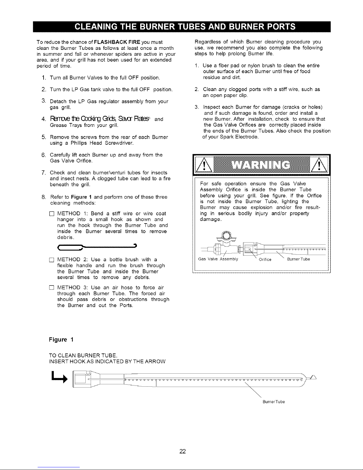
ToreducethechanceofFLASHBACKFIREyoumust
cleantheBurnerTubesasfollowsatleastoncea month
insummerandfallorwheneverspidersareactiveinyour
area,andifyourgrillhasnotbeenusedforanextended
period of time.
1. Turn all Burner Valves to the full OFF position.
Regardless of which Burner cleaning procedure you
use, we recommend you also complete the following
steps to help prolong Burner life.
1. Use a fiber pad or nylon brush to clean the entire
outer surface of each Burner until free of food
residue and dirt.
2. Turn the LP Gas tank valve to the full OFF position.
3. Detach the LP Gas regulator assembly from your
gas grill.
4. F_BITEM_thBagc_Jng(_tids, S_IvCrF_65F and
Grease Trays from your grill.
5. Remove the screws from the rear of each Burner
using a Phillips Head Screwdriver.
6. Carefully lift each Burner up and away from the
Gas Valve Orifice.
7. Check and clean burner/venturi tubes for insects
and insect nests. A clogged tube can lead to a fire
beneath the grill.
8. Refer to Figure 1 and perform one of these three
cleaning methods:
[] METHOD 1: Bend a stiff wire or wire coat
hanger into a small hook as shown and
run the hook through the Burner Tube and
inside the Burner several times to remove
debris.
,)
[] METHOD 2: Use a bottle brush with a
flexible handle and run the brush through
the Burner Tube and inside the Burner
several times to remove any debris.
[] METHOD 3: Use an air hose to force air
through each Burner Tube. The forced air
should pass debris or obstructions through
the Burner and out the Ports.
2. Clean any clogged ports with a stiff wire, such as
an open paper clip.
3.
Inspect each Burner for damage (cracks or holes)
and if such damage is found, order and install a
new Burner. After installation, check to ensure that
the Gas Valve Orifices are correctly placed inside
the ends of the Burner Tubes. Also check the position
of your Spark Electrode.
For safe operation ensure the Gas Valve
Assembly Orifice is inside the Burner Tube
before using your grill. See figure. If the Orifice
is not inside the Burner Tube, lighting the
Burner may cause explosion and/or fire result-
ing in serious bodily injury and/or property
damage.
Gas Valve Assembty Orifice BurnerTube
Figure 1
TO CLEAN BURNER TUBE,
INSERT HOOK AS INDICATED BY THE ARROW
BumerTube
22
Page 23

Burn-Off
[] Before cooking on your gas grill for the first time, you
should "burn off" the grill to eliminate any odor or
foreign matter. Ignite the burners, lower the Lid, and
operate grill on HIGH setting for 3 to 5 minutes.
CAUTION: Operating ALL main burners on HIGH
setting for longer than five minutes may damage
certain parts of your grill. Do not leave your grill unat
tended when in use.
Preheating
[] To preheat, light your grill on HIGH, lower the Lid
and follow this timetable:
• For high temperature cooking, preheat grill 3 to 5
minutes.
• For low temperature cooking, preheat grill 3 minutes.
• To slow cook, preheating is not necessary.
Cooking Temperatures
[] High setting: The HIGH Control Knob setting should
only be used to pre-heat your grill the first 3-5 minutes
and for burning food residue off the grill for 3-5 minutes
after cooking is complete.
CAUTION: Operating ALL main burners on HIGH setting
for longer than five minutes may damage certain parts
of your grill. Do not leave your grill unattended when in
use.
IndirectCooking
[] The indirect cooking method can also be used with
the supplied Cooking Grids. To cook indirectly, the
food should be placed on the left or right side of your
grill with the Burner lit on the opposite side. Or place
your food on the Secondary Cooking Rack and light
the outer grill Burners. Either way, indirect cooking
must be done with the Lid down.
Prepare Cooking Grids for Grilling
[] Greasing the cooking surface will help keep foods
from sticking during the cookout and reduces the
amount of cleanup required. Use a brush to apply a
thin layer of cooking oil or vegetable shortening onto
each Cooking Grid before each cookout. We do not
suggest spray type oils unless they are specified for
high-temperature cooking. Be sure to coat the entire
cooking surface including edges and any areas with
chipped porcelain.
Flare-Ups
[] The fats and juices dripping from grilled food can
cause flare-ups. Since flare-ups impart a favorably,
distinctive taste and color to food cooked over an
open flame, they should be accepted up to a point.
To minimize flare-ups use a drip pan under foods
that produce a lot of grease, like ribs.
[] Medium to Low Settings: Most recipes specify
medium to low settings, including all smoking,
rotisserie cooking and cooking lean cuts such as fish.
An Important Note About Cooking Temperatures
[] The suggested heat settings and cooking times
shown in the following pages are approximate.
Unlike the controlled environment inside your kitchen,
variables including outside temperatures, direction
and conditions of wind, as well as grill location will
affect your grill's heat distribution. Because these
condition vary, and no two backyards are alike, we
offer this guide as a convenience. We recommend
you monitor your grill closely and rotate foods as
needed to prevent overcooking and ensure the most
delicious results every time.
• The middle and back primary cooking areas offer the
highest heat for searing and grilling.
• The Secondary Cooking Rack offers medium heat for
preparing breads and firm vegetables like potatoes
and corn.
• The front primary cooking area offers less heat and is
ideal for preparing delicate foods and for keeping
cooked foods warm.
DirectCooking
[] The direct cooking method can be used with the
supplied Cooking Grids and food placed directly over
the lit grill Burners. Direct Cooking requires the Grill
Lid to be open. This method is ideal for searing,
grilling, deep frying and whenever you want foods to
have an open-flame barbecued taste.
• Failure to comply with these instructions could
result in a fire or explosion that could cause
serious bodily injury, death or property damage.
• Never cover the cooking grids, bottom of grill bowl
or Grease/Water Tray with charcoal, aluminum foil,
sand or any substance that can absorb grease.
• Before each use of your grill: Pull out the Grease/
Water Tray and remove all grease and food debris to
prevent grease fire hazard. It is important to keep this
Tray filled with water while grilling to get the best
possible results. Wear a flame retardant BBQ Mitt
when handling the Grease/Water Tray.
• Use your grill at least 5 feet away from any
wall or surface. Use your grill at least 5 feet
away from combustible objects that can melt or
catch fire (such as vinyl or wood siding, fences
and overhangs) or sources of ignition including
pilot lights on water heaters and live electrical
appliances.
• Never use your gas grill in a garage, porch, shed,
breezeway or any other enclosed area.
• Your grill will get very hot. Always wear a flame
retardant BBQ Mitt when cooking on your grill and
handling the Grease/Water Tray. Never lean over
cooking areas while using grill. Do not touch cooking
surfaces, Lid, grill housing or other parts while grill
in operation, or until the grill has cooled down after
use. Be aware that the Tray does contain water and
grease and be extremely careful when removing to
prevent spillage.
A-1
Page 24

Grilling Steak and Ribs
Turn the grill Burners on HIGH, close the Lid and preheat
your grill 3 to 5 minutes. Open Lid and place the meat on
the Cooking Grid directly above the lit Burners. Cook the
meat on both sides until seared. Reduce the heat to
MEDIUM and cook meat until done. Grilling times will vary
according to meat thickness.
Grilling Hamburgers and Sausages
Turn the grill Burners on HIGH, close Lid and preheat your
grill 3 to 5 minutes. Open Lid and place the meat on the
Cooking Grid directly above the lit Burners. Cook the meat
on both sides until seared. Reduce the heat to MEDIUM
and cook the meat until done. Grilling times will vary
according to meat thickness.
Grilling Poultry
Turn the grill Burners on HIGH, close Lid and preheat your
grill 2 to 3 minutes. Then raise the Lid, reduce heat to
MEDIUM and cook poultry directly over lit Burners until
done. Poultry skin is fatty so you should expect some
flare-ups when using this direct method.
To minimize flare-ups, try grilling poultry using the indirect
method. Place the poultry on one side of the grill with the
opposing Burners on MEDIUM heat, and lower the grill
Lid. Grilling times will vary based on the size of your
poultry.
Cut of Meat
T-bone steak
Sirloin steak
Beef spare ribs
Porterhouse steak
New York strip steak
Hamburgers
Sausages
Chicken breast
(cook with bone down)
Chicken wings
Drumsticks
Whole bird
(cook with breast up)
Approximate Cooking Times
Rare: 4-8 minutes
Medium: 10-14 minutes
Well done: 15-20 minutes
Rare: 4-6 minutes
Medium: 8-10 minutes
Well done: 10-15 minutes
Direct method:
approximately 15 minutes
Indirect method:
up to 30 minutes
Indirect method:
approximately 1 hour
Grilling Pork
Turn Burners on HIGH and preheat your grill 3 to 5
minutes with the Lid closed. Raise Lid, place pork on
Cooking Grid and cook until seared. Reduce heat to
MEDIUM and cook until done. Grilling times will vary
according to meat thickness.
Whole Fish and Whole Fillets
Preheat your grill on HIGH for 2-3 minutes with the Lid
down. Raise lid and turn Burners to MEDIUM heat. Place
fish (skin down) on grill and cook over direct heat until
done. Use cooking time as a guide or until fish is opaque
but still moist.
Smaller Fish Fillets and Cubes
Follow the directions from above, using approximate
cooking times shown at right. Place a small piece of
aluminum foil on the Cooking Grids if the fish pieces are
small enough to drop between the Cooking Grids.
Vegetables and Fruit
Prepare your fruit or vegetables and brush with butter or
basting sauce if desired. To cook indirectly, the food
should be placed on the left or right side of your grill with
the Burner lit on the opposite side and the grill lid down.
Or center your food on the Secondary Cooking Rack and
light the outer grill Burners. Either way, indirect cooking
must be done with the Lid down.
In some instances, you may want to grill vegetables and
fruit directly over the heat, using the supplied Cooking
Grids. Foods that work best with direct heat are relatively
soft and require a short cooking time: mushrooms,
zucchini, tomatoes and skewered fruit such as apricots,
peaches, pineapple, strawberries and kiwis. Remember
the Grill Lid must remain up when cooking directly.
Chops
Loins
Medium: 10-14 minutes
Well done: 15-20 minutes
Cutlets
Whole fish
Whole fish fillets
Fish fillets
Boneless cubes
For very firm vegetables--particularly potatoes and yams,
we recommend that you partially boil until almost cooked,
before placing them on the grill. Cooking times using the
indirect method with the lid down will be similar to those
for your kitchen oven. However, there are many factors
such as outside temperature, wind conditions and
location of grill that affect your grill performance so we
suggest you watch the temperature gauge and adjust the
heat accordingly.
Cooking times for foods prepared with the direct method
will be much shorter mainly because of the direct heat
source and softness of the food. Timing will be compa-
rable to normal pan frying or grilling.
10 - 12 minutes per pound or
until fish is opaque
4 - 5 minutes each side
or until fish is opaque
A-2
Page 25
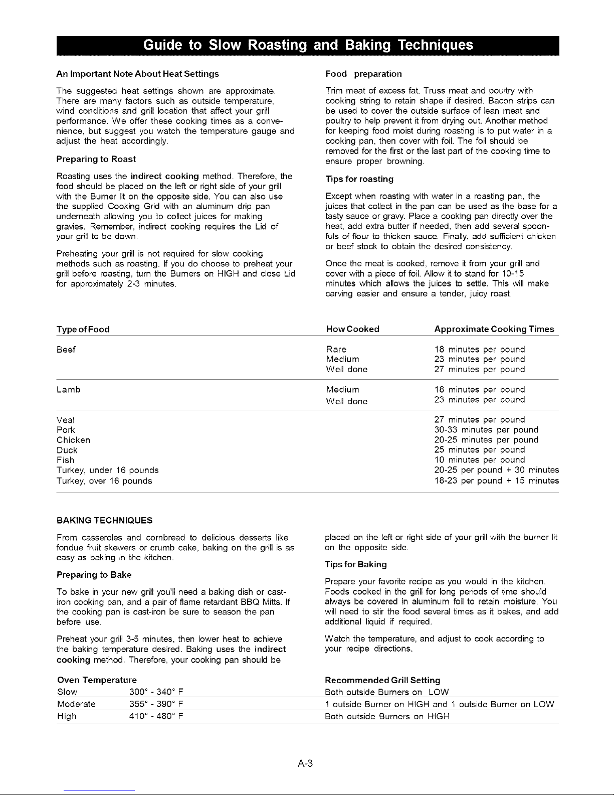
An Important Note About Heat Settings
The suggested heat settings shown are approximate.
There are many factors such as outside temperature,
wind conditions and grill location that affect your grill
performance. We offer these cooking times as a conve-
nience, but suggest you watch the temperature gauge and
adjust the heat accordingly.
Preparing to Roast
Roasting uses the indirect cooking method. Therefore, the
food should be placed on the left or right side of your grill
with the Burner lit on the opposite side. You can also use
the supplied Cooking Grid with an aluminum drip pan
underneath allowing you to collect juices for making
gravies. Remember, indirect cooking requires the Lid of
your grill to be down.
Preheating your grill is not required for slow cooking
methods such as roasting. If you do choose to preheat your
grill before roasting, turn the Burners on HiGH and close Lid
for approximately 2-3 minutes.
Type of Food How Cooked Approximate Cooking Times
Beef Rare 18 minutes per pound
Food preparation
Trim meat of excess fat. Truss meat and poultry with
cooking string to retain shape if desired. Bacon strips can
be used to cover the outside surface of lean meat and
poultry to help prevent it from drying out. Another method
for keeping food moist during roasting is to put water in a
cooking pan, then cover with foil. The foil should be
removed for the first or the last part of the cooking time to
ensure proper browning.
Tips for roasting
Except when roasting with water in a roasting pan, the
juices that collect in the pan can be used as the base for a
tasty sauce or graw. Place a cooking pan directly over the
heat, add extra butter if needed, then add several spoon-
fuls of flour to thicken sauce. Finally, add sufficient chicken
or beef stock to obtain the desired consistency.
Once the meat is cooked, remove it from your grill and
cover with a piece of foil. Allow it to stand for 10-15
minutes which allows the juices to settle. This will make
carving easier and ensure a tender, juicy roast.
Medium 23 minutes per pound
Well done 27 minutes per pound
Lamb Medium 18 minutes per pound
Well done 23 minutes per pound
Veal 27 minutes per pound
Pork 30-33 minutes per pound
Chicken 20-25 minutes per pound
Duck 25 minutes per pound
Fish 10 minutes per pound
Turkey, under 16 pounds 20-25 per pound + 30 minutes
Turkey, over 16 pounds 18-23 per pound + 15 minutes
BAKING TECHNIQUES
From casseroles and combread to delicious desserts like
fondue fruit skewers or crumb cake, baking on the grill is as
easy as baking in the kitchen.
Preparing to Bake
To bake in your new grill you'll need a baking dish or cast-
iron cooking pan, and a pair of flame retardant BBQ Mitts. If
the cooking pan is cast-iron be sure to season the pan
before use.
Preheat your grill 3-5 minutes, then lower heat to achieve
the baking temperature desired. Baking uses the indirect
cooking method. Therefore, your cooking pan should be
Oven Temperature
Slow 300 ° - 340 ° F
Moderate 355 ° - 390 ° F
High 410 ° - 480 ° F
placed on the left or right side of your grill with the burner lit
on the opposite side.
Tips for Baking
Prepare your favorite recipe as you would in the kitchen.
Foods cooked in the grill for long periods of time should
always be covered in aluminum foil to retain moisture. You
will need to stir the food several times as it bakes, and add
additional liquid if required.
Watch the temperature, and adjust to cook according to
your recipe directions.
Recommended Grill Setting
Both outside Burners on LOW
1 outside Burner on HiGH and 1 outside Burner on LOW
Both outside Burners on HiGH
A-3
Page 26

Slow Cooking with a Rotisserie
Rotisserie cooking produces foods that are moist,
flavorful and attractive. The optional rotisserie system
is most commonly used for cooking meat or poultry
and is designed to cook food slowly. You can place a
cooking pan beneath the food to collect juices for
basting and gravy. To flavor the contents of the cooking
pan you may add herbs, onions, or other spices of your
choice.
The cooking times on a rotisserie will be approximately
the same as for oven cooking.
Balancingthe Food
In rotisserie cooking, balancing the food is of utmost
importance. The rotisserie must turn evenly or the
stopping and starting action will cause the food to cook
unevenly and possibly burn the heavier side.
The easiest foods to balance are those of uniform
shape and texture. To test if the food is balanced
correctly when secured, place the ends of the rotis-
serie spit loosely in the palms of your hands. If there is
no tendency to roll, give the spit a quarter turn. If it is
still stable, give it a final quarter turn. It should rest
without turning in each of these positions. It can then
be attached to your grill.
Food Preparation
When preparing poultry, truss the birds tightly so that
wings and drumsticks are close to the body of the bird.
The cavity of the bird may be stuffed prior to this. Pull the
neck skin down and, using a small skewer, fix it to the
back of the bird. Push the rotisserie spit through length-
wise, catching the bird in the fork of the wishbone. Center
the bird and tighten with the holding forks. Test the
balance as described before.
Preparing to Smoke
Smoking gives food a distinctive, delicious flavor. You will
find a variety of wood chips available for use in smoking
grilled foods. Pre-soaking of wood chips may be re-
quired so read and follow the manufacturers instructions
for preparing smoking chips prior to use.
Note: It is our experience that many smoking chip
products do not actually produce a smoke but instead
infuses the food with flavor. Please read product labels
carefully and if in doubt, ask your retailer for details.
Using A Smoker Box
There are many optional smoker boxes available for
purchase. Follow these guidelines and always refer to
the label of your smoking chips for specific directions.
Raise your Grill Lid and light the grill. Lower the Grill Lid
allowing your grill to reach the desired cooking tempera-
ture for the food you are grilling. Fill your smoker box with
your prepared smoking chips. Dried herbs and spices
may also be added to produce different flavors. Wear a
flame retardant BBQ Mitt and place your smoker box on a
Cooking Grid or Savor Plate® directly above a lit grill
Burner. The heated smoking chips will flavor your foods.
Tips for Smoking
You can reduce the strength of the smoke flavor by only
smoking for half or three quarters of the cooking time.
The heat required for smoking is normally LOW to
MEDIUM.
Foods naturally high in oils lend themselves well to
smoking, while drier foods benefit from a marinade.
A rolled piece of meat requires the rotisserie skewer to be
inserted through the center of the length of meat, then
secured and balanced.
For meats that contain bones, it is best to secure the
rotisserie skewer diagonally through the meaty sections. If
protruding bones or wings brown too quickly, cover with
pieces of foil.
• Tuna steaks, marinated in Asian flavors of sesame
oil, soy sauce and sherry.
• Pork fillets, rubbed with ginger, orange rind and
brushed with maple syrup.
• Mussels, brushed with lemon rind and chili oil.
• Lamb cutlets, marinated in virgin olive oil, lemon,
oregano and black pepper. The same marinade can
be used for a whole leg or rack of lamb.
• Chicken, boneless chicken pieces--especially sliced
breasts.
• Fish, sliced fillets of firm fish, assorted seafood such
as prawns, scallops and calamari.
• Pork, sliced fillets, diced or minced pork, sliced leg
steak, sliced chops.
• Beef, sliced fillet, rib-eye, round, rump, sirloin.
• Lamb, sliced fillet, round, loin.
A-4
Page 27

STIR-FRYING TECHNIQUES
This method of cooking is popular around the world and
can be easily accomplished outdoors on your gas grill. It's
a quick and healthful way of preparing a complete meal
using meat, poultry or seafood in infinite combinations
with other interesting ingredients like vegetables, rice or
noodles.
DEEP-FRYING TECHNIQUES
A wide variety of foods can be deep-fried outdoors on
your grill, from potatoes, to seafood and chicken. Deep-
frying uses a large portion of oil, preferably saturated.
The outdoor location is ideal for deep-frying as smoke,
grease and smells disperse in the open air instead of
collecting on the ceiling of your kitchen.
Preparing to Stir-fry
Although it is possible to stir fry in other dishes, a wok is
your best tool. Its high sides enable the cook to stir food
without spillage. Its construction allows you to cook quickly
at high temperatures, with instant control of heat which is
essential for successful stir frying.
Food preparation
Slice meat and poultry into long thin strips and cube fish
fillets. Remove all fat from meat and poultry and cut large
vegetables into even slices or cubes.
Marinate foods for extra flavor and tenderness. Marinating
times will vary for red meat, fish and or various cuts. Less
tender cuts of meat should be marinated longer. Remem-
ber to always chili marinating food in the refrigerator prior
to cooking.
Stir-fry meats, poultry or fish first. Next, add hard veg-
etables like carrots. Then continue with softer vegetables
like snowpeas and peppers. To ensure even cooking,
continually stir and toss the food in the wok using a
wooden spoon or spatula.
Tips for Stir-frying
Place a wok on a Cooking Grid or Side Burner directly
over a HIGH heat . Add only a small amount of food at
a time to ensure fast cooking and also to allow the wok
to reheat between ingredients.
Preparing to Deep-fry
Deep-fry on your grill using a cooking pan or wok, over
direct heat.
Fill a cooking pan no more than half full of vegetable or
corn oil. Start with LOW heat, then raise the heat gradu-
ally. Check the temperature of the oil carefully with a
frying thermometer or test with a cube of bread. The
cube of bread should brown in about 30 seconds for
most cooking needs. A temperature between 350 and
400 degrees is optimal for preparing the majority of
deep-fried foods.
Food Preparation
Foods being deep-fried taste better when coated with
either batter or breadcrumbs to add flavor and prevent
moisture from escaping.
Tips for Deep-frying
Wear a flame retardant BBQ Mitt and slowly lower
foods into the hot oil using a wire scoop or stainless
steel tongs. Add only a small quantity of food to the
oil, allow it to cook, then repeat with another small
quantity. This ensures the oil doesn't drop in tem-
perature. Once the food is cooked, remove it carefully
and drain onto a paper towel. Turn the heat off as
soon as you have finished deep-frying and allow your
pan to cool. When the oil is cool, remove all rem-
nants of fried foods by straining it through a fine
metal sieve, and store it in a clean bottle for future
use.
Vegetables are generally easy to cook on the grill. The
Cooking Rack makes it convenient because you can still
use the main cooking area while the vegetables are
suspended above the grids.
Pre-cook hard vegetables by briefly boiling or
microwaving them before cooking on the grill. Wrap
vegetables in a double thickness of foil to protect them
while cooking on the grill. Then, remove the foil if desired,
10-15 minutes before the end of cooking, brush veg-
etables with butter or oil and finish cooking.
The Cooking Rack can be used for purposes other than
just the obvious. Consider using the rack for warming
French bread, garlic bread, croissants or even bagels.
A small whole fish wrapped in foil also cooks well on the
Cooking Rack. Parcels of seafood such as scallops,
prawns and sliced fish fillets prepared in a sauce and
portioned into small foil wraps cook well this way, too.
A-5
Page 28

Anything you enjoy cooking indoors can be
prepared outdoors as well. These optional
grill accessories make it easy to enjoy your new
Kenmore Premium or Kenmore Elite grill as an
outdoor kitchen.
Rotisserie cooking produces foods that are moist and
flavorful because the slowly rotated food self-bastes to
seal in meat's natural juices. Use a Rotisserie Kit to slow
cook foods using the indirect cooking method or an
infrared back burner, a feature available on some models.
Not all locations carry all items and availability is
limited to supplies on hand. Accessory fit will vary
by grill model so ask a sales associate for details.
Grill accessories are offered at most larger
Sears full line stores, Sears Grand, Sears
Hardware, The Great Indoors, Orchard Supply
Hardware and sears.com.
Versatile cast-iron Pan
and Lid set is ideal for
preparing deep dish pizza,
cornbread, casseroles
and deserts.
Reversible cast-iron
Griddle offers a flat side
for grilling breakfast,
fish and fajitas and a
ribbed side for cooking
bacon, sausages and
burgers.
Load this Smoker Box with
your favorite chips and add
flavor to grilled foods.
Quality 304 grade
stainless steel grill tools
offer long reach handles
for easier outdoor
cooking.
Protect your grill from rain, snow and
with a quality made grill cover. Fit varies by grill model.
Call the Grill Information Center if you have any problem with this product. We can help with questions about
assembly, grill operation, accessory availability or if there are damaged or missing parts when you unpack this
unit from the shipping box. Please call us before contacting your local retailer.
Call 8am to 8pm CST 1-888-317-7642 Monday through Friday
GRILL INFORMATION CENTER
A-6
Page 29

Question:
Can I convert my grill from one fuel type to another in
other words from LPG to NG or vice versa?
Answer:
No, your gas grill is manufactured to exact specifications
and is certified for LPG (Liquid Propane Gas) or NG
(Natural Gas) use only. For your safety, conversion kits
are not available, nor will we sell or otherwise provide
parts or information to be used to convert your grill. Any
attempt to convert your grill is dangerous and will void
your warranty.
Question:
Are the serial and model numbers of my grill listed
somewhere for reference?
Answer:
The serial and model numbers are listed on a silver
CSA label placed on the grill. Depending on the grill
model, the silver CSA label will be located on the left or
right side bowl panel underneath the side shelf,
underneath the right side of the control panel, outside
left or right of control panel or on the back of the grill
cabinet.
Question:
My grill will not light properly. Why?
Answer:
Try this procedure:
1. Turn gas off at source and turn Control Knobs OFF.
Wait at least 5 minutes for gas to clear, then retry.
2. If your grill still fails to light, turn the Burner Control
Knob(s) and gas source OFF and conduct a leak test
of ALL gas connections and gas sources as
explained in the Use and Care section of this manual.
3. If no leaks are detected, wait 5 minutes for any gas to
clear and repeat the lighting procedure.
Question:
If my ignitor or battery is not working how can I light
my grill manually? And - Why would I need the silver
lighting stick that hangs from the side of my grill?
Answer:
If your ignition fails to work or your battery needs
replacing, you can light your grill through the Lighting
Hole on the side of the grill bowl using the Manual
Lighting Stick that hangs from the side of your grill. The
Lighting Stick is designed to hold a paper match and
allows you to safely insert a match through the Lighting
Hole without getting close to the Burner. Never remove
the Cooking Grids and attempt to light the grill from
above. To light your gas grill manually, insert a paper
match into the Manual Lighting Stick and follow steps 1
through 6 of the Basic Lighting Procedures. Then, light
the match and place it through the Lighting Hole on the
left side of the grill (location of hole varies by grill
model). Turn the nearest main Burner Control Knob to
the High setting to release gas. The Burner should light
immediately.
Question:
Sometimes I hear a humming sound coming from my
regulator, What causes this? And- My grill has a low
flame and sometimes will not light, Why?
Answer:
The humming sound is gas flowing through the
regulator. A low volume of sound is normal and will not
interfere with the operation of your grill. Loud or
excessive regulator humming and/or low flow and
intermittent lighting may be caused by the regulator's
excess gas flow device. Opening the tank valve all the
way or too quickly is what triggers the regulator's
safety device to restrict gas flow, preventing excess
gas flow to your grill. Lighting the main Burner farthest
from the fuel source every time will help eliminate air
pockets in the manifold. Note: This procedure should
be done every time a new LP Gas tank is connected to
your grill.
[] Turn all Control Knobs to the OFF position.
[] Turn off the LP Gas tank at the tank valve.
[] Disconnect regulator from LP Gas tank.
[] Let unit stand for 5 minutes.
[] Reconnect regulator to the LP Gas tank.
[] Open grill Lid (or Side Burner Lid if you are lighting
the Side Burner)
[] Turn the tank valve slowly _¼ of one turn.
[] Light the left main Burner.
[] Turn the tank valve slowly one more t/4 of one turn
for ½ of one complete turn.
[] Turn Knob for each other burner and light as you
move toward the fuel source.
[] Do not turn tank valve more than ½ of one turn.
Question:
Where do I use my grill for safer operation and
better performance?
Answer:
[] Strong winds and low temperatures can affect the
heating and performance of your gas grill so
factor in these elements when positioning your
grill outdoors for cooking.
[]
Use your grill at least 5 feet away from any wall or
surface.
[]
Use your grill at least 5 feet away from
combustible objects that can melt or catch fire
(such as vinyl or wood siding, fences and
overhangs) or sources of ignition including pilot
lights on water heaters and live electrical
appliances.
A-7
[]
Never use your gas grill in a garage, porch, shed,
breezeway or any other enclosed area.
[]
Never obstruct the flow of ventilation air around
your gas grill housing.
Page 30

Question:
The Regulator and Hose supplied with my gas grill
does not fit the older LP Gas tank I've used for
years. Why not?
Answer:
The U.S. Government regulates gas appliances and
LP Gas tanks. When regulations are changed the LP
Gas tank fittings are altered to insure compliance. If
your LP Gas tank does not fit the Regulator and Hose
supplied with your new grill, the tank is outdated and
must be replaced. Note: Effective April 1, 2002 all LP
Gas tanks sold must include an "OPD" Overfill
Prevention Device. The OPD tanks are identified by
their triangular-shaped valve wheel. This internal
device prevents the LP Gas tank from being
overfilled. Tanks without an OPD valve can not be
refilled.
Question:
Is it safe to clean my porcelain coated cooking grids
in the dishwasher?
Answer:
Clean your cooking grids by hand if there are any chips
or cracks in the porcelain finish and dry them thoroughly.
If no chips or cracks are present it should be safe to use
the dishwasher. Remember to dry the cooking grids
thoroughly before placing back onto your grill to
minimize rusting.
Question:
What causes grill parts to rust and what affect does
it have on my grill?
Answer:
Rusting is a natural oxidation process and may
appear on cast-iron and steel parts. Rust will not
affect the short term performance of your grill.
To slow the rusting process on steel Cooking Grids
(select models) we recommend greasing the
Cooking Grids before and after each cookout. Use a
brush to apply a thin layer of cooking oil or vegetable
shortening onto each Cooking Grid. We do not
suggest spray type oils unless they are specified for
high-temperature cooking. Be sure to coat the entire
cooking surface including edges and any areas with
chipped porcelain.
Question:
Which is a better cooking surface to grill on;
porcelain coated steel / cast-iron cooking grids or
stainless steel grids?
Answer:
They all have their advantages. For traditional grilling
and searing meats, cast-iron or steel grids offer
better heat conductivity. To protect against the natural
rusting process, steel or cast-iron cooking grids offer
a porcelain finish which requires routine
maintenance to keep the grids well seasoned.
Stainless steel is popular with those who prefer less
maintenance.
A new innovative solution is available on select
models called Stainless Clad Therma-Core R. This
Cooking Grid combines a heat conducting steel core
with an easy-to-clean stainless outer shell.
A-8
Page 31

Congratulations on making a smart purchase. Your new Kenmore _>product is designed and manufactured for years
of dependable operation. But like all products, it may require preventive maintenance or repair from time to time.
That's when having a Master Protection Agreement can save you money and aggravation.
The Master Protection Agreement also helps extend the life of your new product. Here's what the Agreement*
includes:
[]
[]
[]
[]
[]
[]
[]
[]
[]
[]
[]
Once you purchase the Agreement, a simple phone call is all that it takes for you to schedule service. You can call
anytime day or night, or schedule a service appointment online.
Parts and labor needed to help keep products operating properly under normal use, not just defects. Our
coverage goes well beyond the product warranty. No deductibles, no functional failure excluded from
coverage - real protection.
Expert service by a force of more than 10,000 authorized Sears service technicians, which means
someone you can trust will be working on your product.
Unlimited service calls and nationwide service, as often as you want us, whenever you want us.
"No-lemon" guarantee - replacement of your covered product if four or more product failures occur within
twelve months.
Product replacement if your covered product can't be fixed.
Annual Preventive Maintenance Check at your request - no extra charge.
Fast help by phone - we call it Rapid Resolution - phone support from a Sears representative on all
products. Think of us as a "talking owner's manual."
Power surge protection against electrical damage due to power fluctuations.
$250 Food Loss Protection annually for any food spoilage that is the result of mechanical failure of any
covered refrigerator or freezer.
Rental reimbursement if repair of your covered product takes longer than promised.
10% discount off the regular price of any non-covered repair service and related installed parts.
The Master Protection Agreement is a risk free purchase. If you cancel for any reason during the product warranty
period, we will provide a full refund. Or, a prorated refund anytime after the product warranty period expires.
Purchase your Master Protection Agreement today!
Some limitations and exclusions apply. For prices and additional information in the U.S.A. call 1-800-827-6655.
* Coverage in Canada varies on some items. For full details call Sears Canada at 1-800-361-6665.
Sears Installation Service
For Sears professional installation of home appliances, garage door openers, water heaters, and other major
home items, in the U.S.A. or Canada call 1-800-4-MY-HOME_(
A-9
Page 32

Your Home
For repair -in your home - of aft major bra_d applances_
_awn and garden equipment_ or heating and cooling system&
no ma_er who made it, no ma_er who sold it!:
IFo[ the replacement pa_s, accessories and
owneCs manuals that you need to doAt-yourseE
For Sears ona_ insta/ation ot home app/a_ces
and iitems ike garage door openers and water heaters.
I_0O4-MY-HOME ¢
Ca/an_ime, day or night (U.S.A. a_d Ca_ada)
_w,_ea_'s,com www.sea_s.ca
For exDert ho,tYce s ad_,_c/9:www, maBagemyho_e°co_
Our Home
For repair of carry-in items ike vacuums, _awn equipment,
and electronics, call or go on-line for the location d your nearest
Sears Pa_$ & Repair Se_ice Center
1-800-488-t222 (U.S.A.) _-800-469-4663 (Canada)
Cal anytime day or _ight
www,sears._om _w.sea[a.ca
To purchase a protection agreement on a produd sewiced by Sears:
Para _dr servicio d_ rep_racidn
a domici/o, y para ordena_ piezas:
(1-888-784-6427)
t-800-361-6665 (Canada)
 Loading...