

Kenmore ELITE 141.16655900, 141.16655900 Use And Care Manual
Use and Care Guide
E L ! T
LiquidPropaneGas(LPG)
GrillIsland
Model141.16655900
-®
• Safety
• Assembly
• Use and Care
• Cooking Guide
• Frequently Asked Questions
Call us first if you have any problem with
this product. We can help you with ques-
tions about assembly and grill operation or
if there are damaged or missing parts
when you unpack this unit from the ship-
ping box. Please call before contacting
your local retailer.
1- 888-317-7642
8am-8pm CST, Monday throu,qh Friday
NOTE TO ASSEMBLER/INSTALLER:
Leave this guide with the consumer.
NOTE TO CONSUMER:
Keep this guide for future reference.
• RECORDYOURSERIAL#
(see silver CSA label on main body of grill)
• Failure to comply with these instructions could
result in a fire or explosion that could cause
serious bodily injury, death or property damage.
• Whether this grill was assembled by you or
someone else, you must read this entire manual
before using your grill to ensure the grill is
properly assembled, installed and maintained.
• Use your grill at least 3 feet away from any
wall or surface. Use your grill at least 3 feet
away from combustible objects that can melt or
catch fire such as vinyl or wood siding, fences
and overhangs or sources of ignition including
pilot lights on water heaters and live electrical
appliances.
• THIS GASAPPLIANCE ISDESIGNED FOROUT-
DOOR USE ONLY.
• Never use your gas grill in a garage, porch,
shed, breezeway or any other enclosed area.
• Never obstruct the flow of ventilation air
around your gas grill housing.
• Never disconnect the gas regulator or any gas
fitting while your grill is lit. A lit grill can ignite
leaking gas and cause afire or explosion which
could result in property damage, personal injury
or death.
Guide# P80136008L- Date:2009/04/09
Sears, Roebuck and Co., Hoffman Estates, IL 60179, USA www.sears.com
Primary Safety Warnings ............................ 1-3
Warranty Terms and Conditions .................... 2
Pre-Assembly Instructions ................................ 3
Part Diagrams and Lists ............................ 4-8
Assembly Instructions .................................. 9-11
Use & Care Instructions:
• Gas Safety and Leak Tests .............. 12-15
• Lighting Instructions ................................... 16
• Troubleshooting ........................................... 17
• Rotisserie Instruction ............................. 18-20
Cleaning and Maintenance ....................... 21-22
Cooking Guide .......................................... A1-A5
Frequently Asked Questions .................. A7-A8
Repair Protection Agreements ..................... A9
Kenmore Elite Full Warranty
If this grill fails due to a defect in material or
workmanship within two years from the date of
purchase, call 1-800-4-MY-HOME _ to arrange for
free repair (or replacement if repair proves impos-
sible).
Limited Warranty on Stainless Steel Burners
Any stainless steel burner that ever rusts through
will be replaced free of charge. After the second
year from the date of purchase you must pay the
labor cost to have it installed.
Limited Warranty on Selected Grill Parts
For three years from the date of purchase, any
stainless or painted steel part will be replaced free
of charge if it rusts through. After the second year
from the date of purchase you must pay the labor
cost to have it installed.
All warranty coverage excludes ignitor batteries
and grill part paint loss or rusting (except for rust-
through as specified above), which are either
expendable parts that can wear out from normal
use in less than a year, or are conditions that
can be the result of normal use, accident or
improper maintenance.
All warranty coverage is void if this grill is ever
used for commercial or rental purposes.
All warranty coverage applies only if this grill is
used in the United States.
This warranty gives you specific legal rights, and
you may have other rights which vary from state
to state.
Sears, Roebuck and Co., Hoffman Estates, IL
© Sears Brands, LLC
If you smell gas:
1. Shut off gas to the appliance.
2. Extinguish any open flame.
3. Open lid.
4. If odor continues, keep away from
the appliance and immediately call
your gas supplier or your fire
department.
LPG models must be used with Liquid Pro-
pane Gas and the regulator assembly sup-
plied. Natural Gas models must be used with
Natural Gas only. Any attempt to convert the
grill from one fuel type to another is hazardous
and must be performed by a qualified gas
technician only, using a NG Conversion Kit
purchased from Sears at 1-800-4-MY-HOME ®.
Keep gas regulator hose away from hot grill
surfaces and dripping grease. Avoid unneces-
sary twisting of hose. Visually inspect hose
prior to each use for cuts, cracks, excessive
wear or other damage. If the hose appears
damaged do not use the gas grill. Call Sears
at 1-800-4-MY-HOME ® for a certified replace-
ment hose.
California Proposition 65
Combustion byproducts produced when using
this product contain chemicals known to the
State of California to cause cancer, birth de-
fects, or other reproductive harm.
Brass components on the grill, such as hose
fittings, propane cylinder valves (sold sepa-
rately) and burner valve stems, contain lead
which is known to the State of California to
cause cancer, birth defects, or other reproduc-
tive harm.
Never use charcoal or lighter fluid inthis gas
grill. Failure to comply with these instructions
could result in a grease fire or explosion that
could cause serious bodily injury, death or
property damage.
The Grease Draining Tray and Grease Recep-
tacle must be visually inspected before each
grill use. Remove any grease andwash Grease
Draining Tray and Grease Receptacle with a
mild soap and warm water solution. Failure to
complywith these instructions could result
in a grease fire or explosion that could
cause serious bodily injury, death or prop-
erty damage.
Failure to comply with these instructions may result
in a hazardous situation which, if not avoided, may
result in injury.
Spiders and small insects can spin webs and nest
in the grill Burner transit and ware-
housing which flow obstruction
resulting in urner Tubes.
This type _useserious
grill con-
dition
month i
active in
used for at
iK FIRE
follows
once a
3iders are
not been
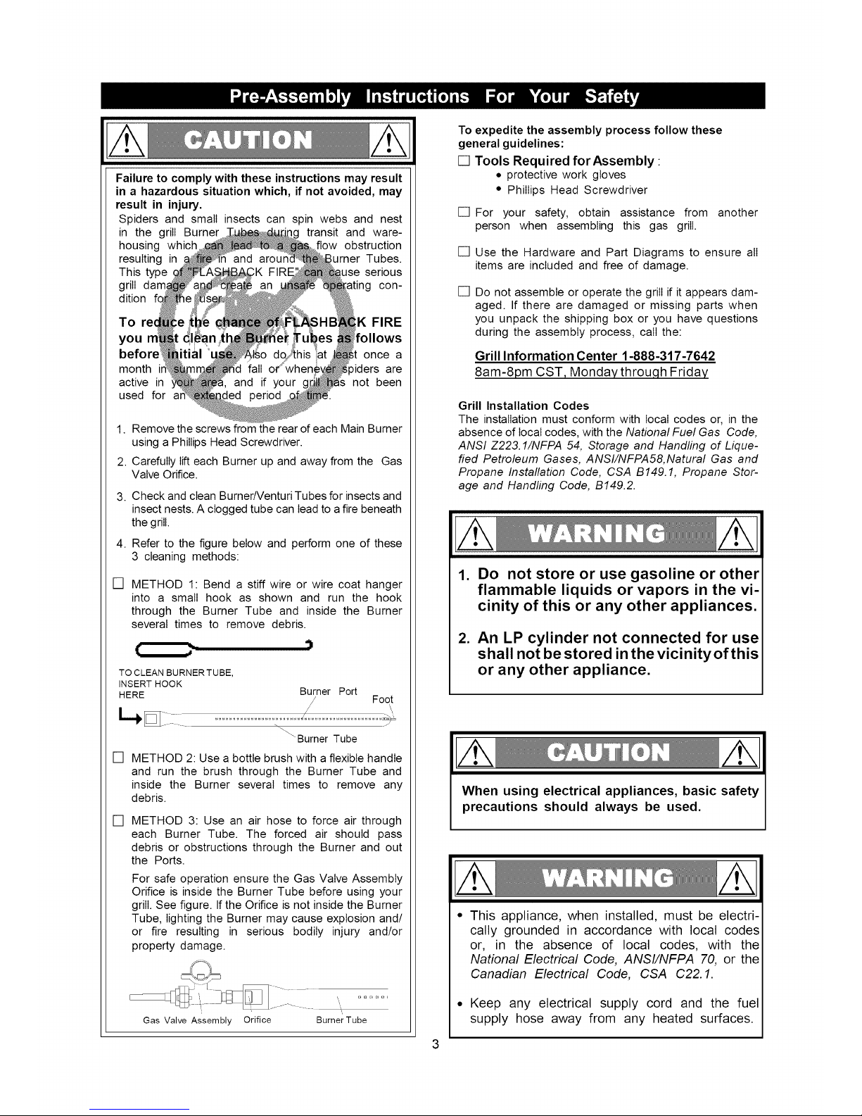
1. Remove the screws from the rear of each Main Burner
using a Phillips Head Screwdriver.
2. Carefully lift each Burner up and away from the Gas
Valve Orifice.
3. Check and clean BurnerNenturi Tubes for insects and
insect nests. A clogged tube can lead to afire beneath
the grill.
4. Refer to the figure below and perform one of these
3 cleaning methods:
[] METHOD 1: Bend a stiff wire or wire coat hanger
into a small hook as shown and run the hook
through the Burner Tube and inside the Burner
several times to remove debris.
I[ Z- "i
TO CLEAN BURNER TUBE,
INSERT HOOK
HERE
Burner Port
/ Foot
\Burner Tube
[] METHOD 2: Use a bottle brush with a flexible handle
and run the brush through the Burner Tube and
inside the Burner several times to remove any
debris.
[] METHOD 3: Use an air hose to force air through
each Burner Tube. The forced air should pass
debris or obstructions through the Burner and out
the Ports.
For safe operation ensure the Gas Valve Assembly
Orifice is inside the Burner Tube before using your
grill. See figure. If the Orifice is not inside the Burner
Tube, lighting the Burner may cause explosion and/
or fire resulting in serious bodily injury and/or
property damage.
Gas Valve Assembly Orifice BurnerTube
To expedite the assembly process follow these
general guidelines:
[] Tools Required for Assembly :
• protective work gloves
• Phillips Head Screwdriver
[] For your safety, obtain assistance from another
person when assembling this gas grill.
[] Use the Hardware and Part Diagrams to ensure all
items are included and free of damage.
[]
Do not assemble or operate the grill if itappears dam-
aged. If there are damaged or missing parts when
you unpack the shipping box or you have questions
during the assembly process, call the:
Grill Information Center 1-888-317-7642
8am-8pm CST, Monday throuqh Friday
Grill Installation Codes
The installation must conform with local codes or, in the
absence of local codes, with the National Fuel Gas Code,
ANSI Z223.1/NFPA 54, Storage and Handling of Lique-
fied Petroleum Gases, ANSI/NFPA58,Natural Gas and
Propane Installation Code, CSA B149.1, Propane Stor-
age and Handling Code, B149.2.
1. Do not store or use gasoline or other
flammable liquids or vapors in the vi-
cinity of this or any other appliances.
2. An LP cylinder not connected for use
shall not be stored in the vicinityofthis
or any other appliance,
When using electrical appliances, basic safety
precautions should always be used.
This appliance, when installed, must be electri-
cally grounded in accordance with local codes
or, in the absence of local codes, with the
National Electrical Code, ANSI/NFPA 70, or the
Canadian Electrical Code, CSA C22. 1.
• Keep any electrical supply cord and the fuel
supply hose away from any heated surfaces.
21
23
6a5
6-.
43
41
L2- .
51.
48
49-
_- . . .
73
51
53
73
_69a
i " 64
70 64a
64b
4
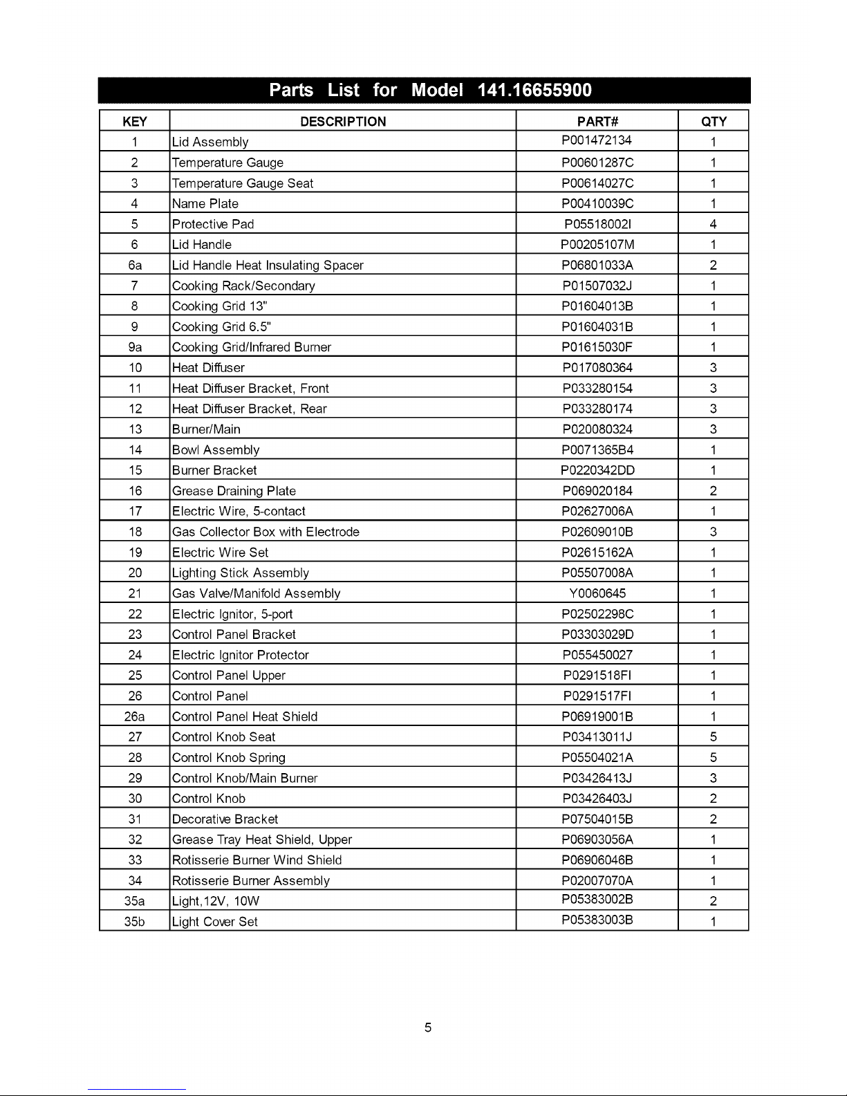
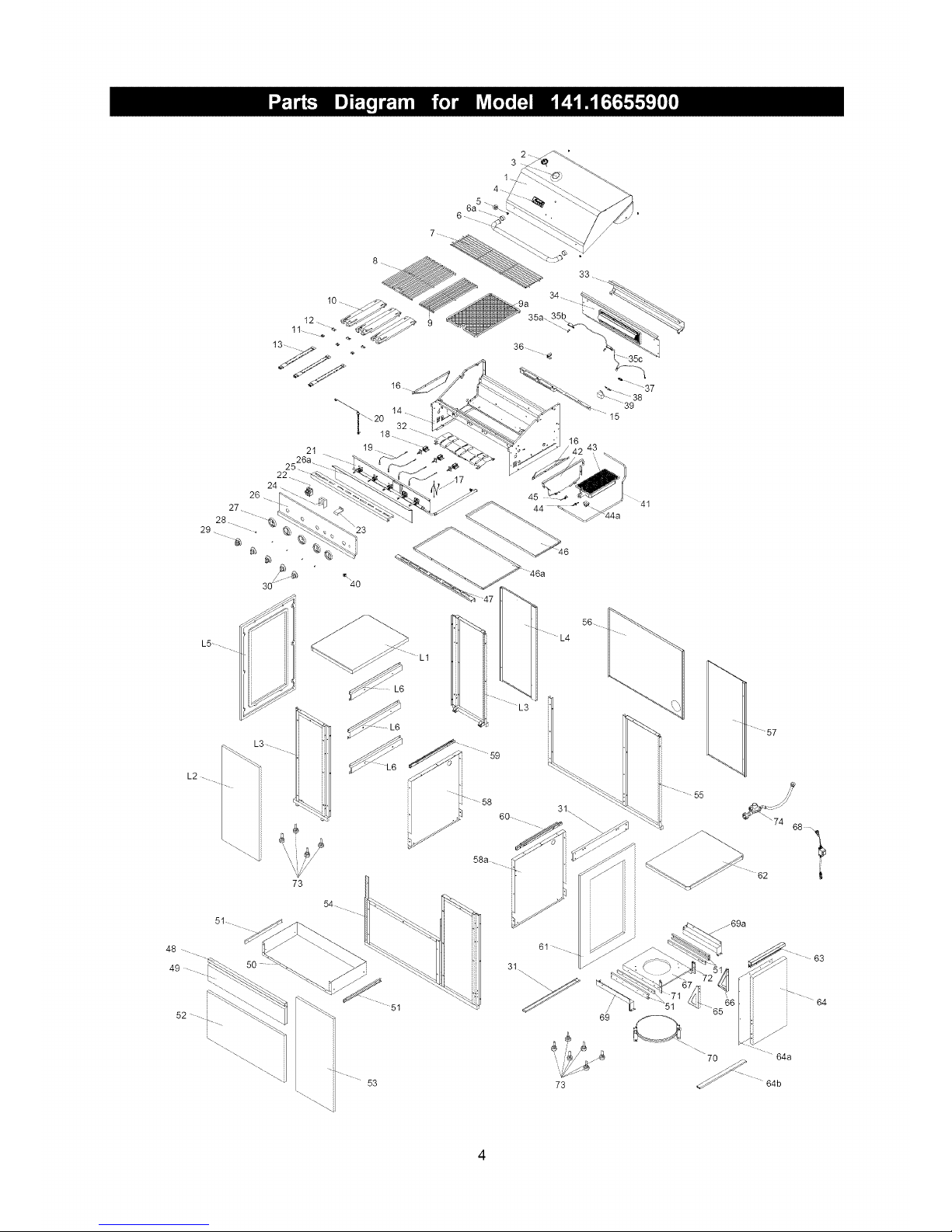
KEY DESCRIPTION PART# QTY
1 LidAssembly P001472134 1
2 TemperatureGauge P00601287C 1
3 TemperatureGaugeSeat P00614027C 1
4 NamePlate P00410039C 1
5 ProtectivePad P055180021 4
6 LidHandle P00205107M 1
6a LidHandleHeatInsulatingSpacer P06801033A 2
7 CookingRack/Secondary P01507032J 1
8 CookingGrid13" P01604013B 1
9 CookingGrid6.5" P01604031B 1
9a CookingGrid/InfraredBurner P01615030F 1
10 HeatDiffuser P017080364 3
11 HeatDiffuserBracket,Front P033280154 3
12 HeatDiffuserBracket,Rear P033280174 3
13 Burner/Main P020080324 3
14 BowlAssembly P0071365B4 1
15 BurnerBracket P0220342DD 1
16 GreaseDrainingPlate P069020184 2
17 ElectricWire,5-contact P02627006A 1
18 GasCollectorBoxwithElectrode P02609010B 3
19 ElectricWireSet P02615162A 1
20 LightingStickAssembly P05507008A 1
21 GasValve/ManifoldAssembly Y0060645 1
22 ElectricIgnitor,5-port P02502298C 1
23 ControlPanelBracket P03303029D 1
24 ElectricIgnitorProtector P055450027 1
25 ControlPanelUpper P0291518FI 1
26 ControlPanel P0291517FI 1
26a ControlPanelHeatShield P06919001B 1
27 ControlKnobSeat P03413011J 5
28 ControlKnobSpring P05504021A 5
29 ControlKnob/MainBurner P03426413J 3
30 ControlKnob P03426403J 2
31 DecorativeBracket P07504015B 2
32 GreaseTrayHeatShield,Upper P06903056A 1
33 RotisserieBurnerWindShield P06906046B 1
34 RotisserieBurnerAssembly P02007070A 1
35a Light,12V,10W P05383002B 2
35b LightCoverSet P05383003B 1
5
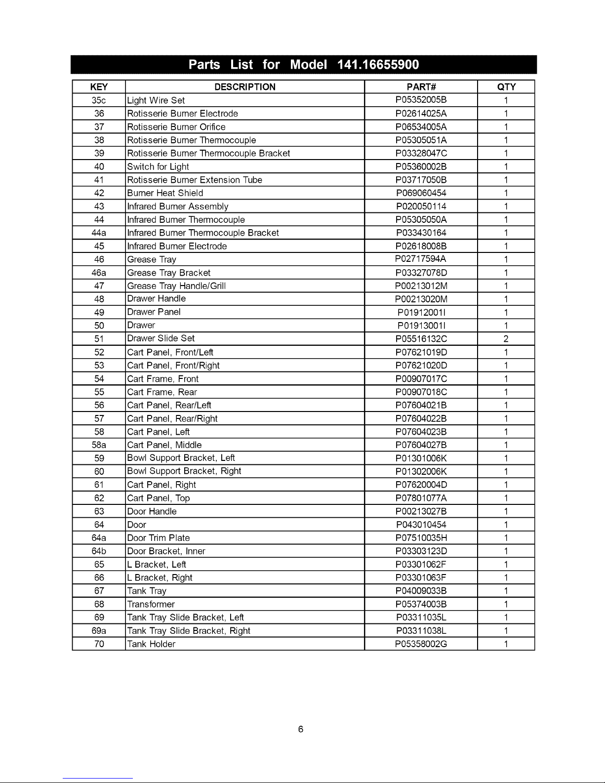
KEY DESCRIPTION PART# QTY
35c LightWireSet P05352005B 1
36 RotisserieBurnerElectrode P02614025A 1
37 RotisserieBurnerOrifice P06534005A 1
38 RotisserieBurnerThermocouple P05305051A 1
39 RotisserieBurnerThermocoupleBracket P03328047C 1
40 SwitchforLight P05360002B 1
41 RotisserieBurnerExtensionTube P03717050B 1
42 BurnerHeatShield P069060454 1
43 InfraredBurnerAssembly P020050114 1
44 InfraredBurnerThermocouple P05305050A 1
44a InfraredBurnerThermocoupleBracket P033430164 1
45 InfraredBurnerElectrode P02618008B 1
46 GreaseTray P02717594A 1
46a GreaseTrayBracket P03327078D 1
47 GreaseTrayHandle/Grill P00213012M 1
48 DrawerHandle P00213020M 1
49 DrawerPanel P019120011 1
50 Drawer P019130011 1
51 DrawerSlideSet P05516132C 2
52 CartPanel,Front/Left P07621019D 1
53 CartPanel,Front/Right P07621020D 1
54 CartFrame,Front P00907017C 1
55 CartFrame,Rear P00907018C 1
56 CartPanel,Rear/Left P07604021B 1
57 CartPanel,Rear/Right P07604022B 1
58 CartPanel,Left P07604023B 1
58a CartPanel,Middle P07604027B 1
59 BowlSupportBracket,Left P01301006K 1
60 BowlSupportBracket,Right P01302006K 1
61 CartPanel,Right P07620004D 1
62 CartPanel,Top P07801077A 1
63 DoorHandle P00213027B 1
64 Door P043010454 1
64a DoorTrimPlate P07510035H 1
64b DoorBracket,Inner P03303123D 1
65 _Bracket,Left P03301062F 1
66 _Bracket,Right P03301063F 1
67 TankTray P04009033B 1
68 Transformer P05374003B 1
69 TankTraySlideBracket,Left P03311035L 1
69a TankTraySlideBracket,Right P03311038L 1
70 TankHolder P05358002G 1
6

KEY DESCRIPTION PART# QTY
71 DoorBracket,Left P033270694 1
72 DoorBracket,Right P033270704 1
73 LevelAdjuster P05322004A 10
74 RegulatorwithHose P03601004A 1
L1 CartPanel,Top P07801072A 1
L2 CartPanel,Front P07621016D 1
L3 CartPanelFrame P03344017D 2
L4 CartPanel,Rear P07702104M 1
L5 CartPanel,Left P07619003D 1
L6 DecorativeBracket P03344018D 3
Cover P07005011B 1
Cover/GrillIsland P07005007A 1
Wrench(PackedwiththeUseandCareGuide) P05515017L 1
WingBolt1/4"xl/2"(AlreadyinstalledontheTankHolder) $233G04084 1
RotisserieAssembly Y0250169 1
UseandCareGuide Pa0136008L 1
OneBattery/AAPackedwiththeUseandCareGuide
To purchase Natural Gas Conversion Parts
call Sears at 1-800-4-MY-HOME ®
Natural gas conversion kit
Part #Y0440037
Your grill can be converted to natural gas
with this conversion kit by a qualified gas
technician only. In order to convert this
grill the technician will need this conver-
sion kit.
Natural gas 12' hose
Part #P03703001A
If converting the grill to use natural gas,
in most cases the technician will need this
optional 12' extension hose with 3/8" ID
(inner diameter).
For the repair or replacement parts you need:
Call anytime 1-800-4-MY-HOME® (1-800-469-4663)
To obtain the correct replacement parts for your gas grill, please refer to the part numbers in this parts list. The
following information is required to ensure you receive the correct parts:
1. Model and Serial Number (see CSA label on grill)
2. Part Number
3. Part Description
4. Quantity of parts needed
Important: Use only Kenmore replacement parts. The use of any part that is not a Kenmore replacement part
can be dangerous and will also void your product warranty. Keep this use and care guide for convenient referral
and for part replacement.
7
/ z5
/
I0 Z
7
2
.J
8 _f
9
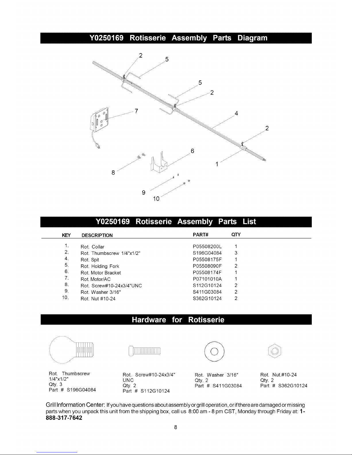
KEY DESCRIPTION PART#
1. Rot. Collar P05508200L
2. Rot. Thumbscrew 1/4"xl/2" $196G04084
4. Rot. Spit P05508175F
5. Rot. Holding Fork P05508090F
6. Rot. Motor Bracket P05508174F
7. Rot. Motor/AC P07101010A
8. Rot. Screw#10-24x3/4"U NC $112G10124
9. Rot. Washer 3/16" $411G03084
10. Rot. Nut #10-24 $362G10124
QTY
1
3
1
2
1
1
2
2
2
Rot. Thumbscrew Rot. Screw#10-24x3/4" Rot. Washer 3/16" Rot. Nut.#10-24
1/4"xl/2" UNC Qty. 2 Qty. 2
Qty. 3 Qty. 2 Part # $411G03084 Part # $362G10124
Part # $196G04084 Part # $112G10124
Grill Information Center: Ifyou have questions about assembly or grill operation, or ifthere are damaged or missing
parts when you unpack this unit from the shipping box, call us 8:00 am - 8 pm CST, Monday through Friday at: 1-
888-317-7642
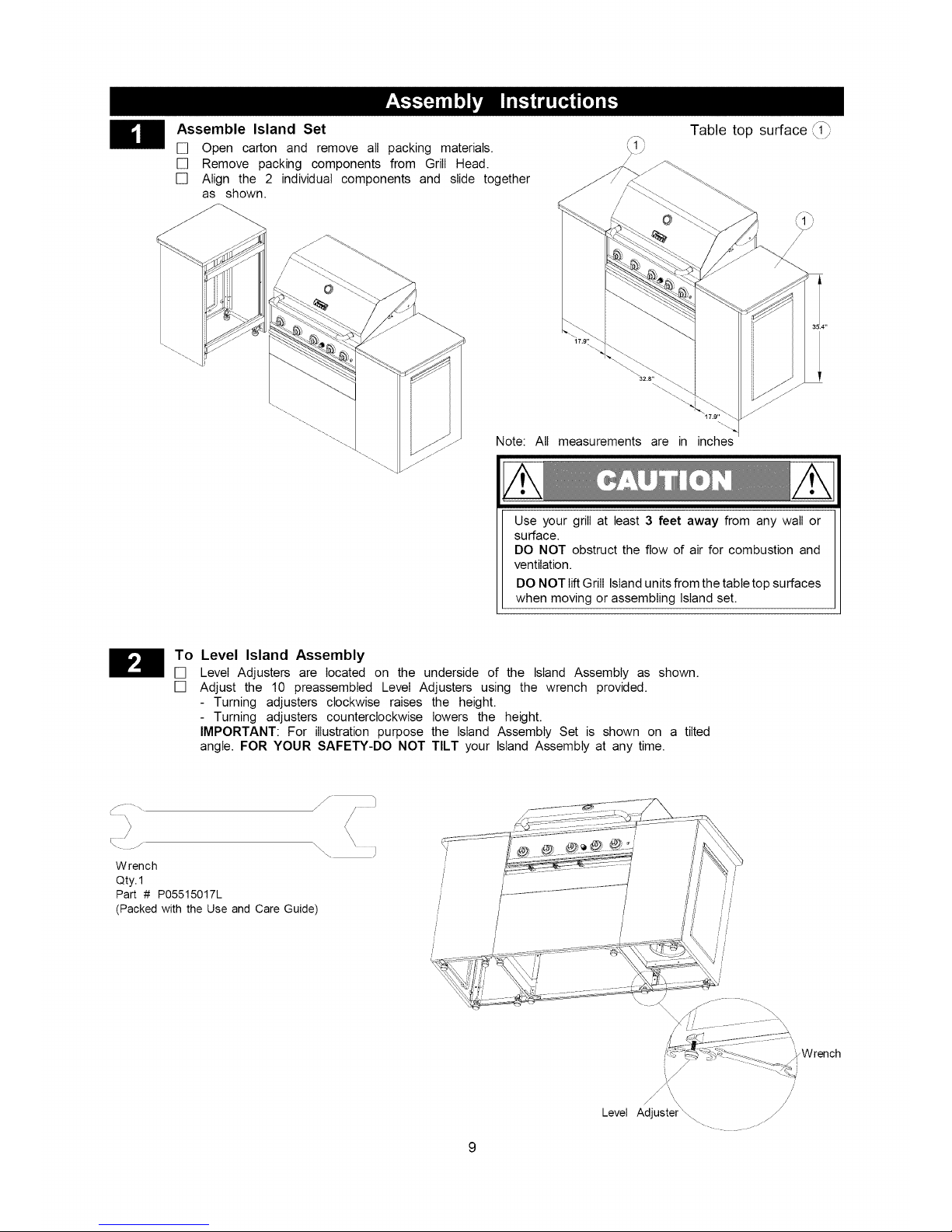
Assemble Island Set
[] Open carton and remove all packing materials.
[] Remove packing components from Grill Head.
[] Align the 2 individual components and slide together
as shown.
Table top surface \_1_
Note: All measurements are in inches
Use your grill at least 3 feet away from any wall or
surface.
DO NOT obstruct the flow of air for combustion and
ventilation.
DO NOT liftGrill Island units from the table top surfaces
when moving or assembling Island set.
H o Level Island Assembly
[] Level Adjusters are located on the underside of the Island Assembly as shown.
[] Adjust the 10 preassembted Level Adjusters using the wrench provided.
- Turning adjusters clockwise raises the height.
- Turning adjusters counterclockwise lowers the height.
IMPORTANT: For illustration purpose the Island Assembly Set is shown on a tilted
angle. FOR YOUR SAFETY-DO NOT TILT your Island Assembly at any time.
\. .J
Wrench
Qty.1
Part # P05515017L
(Packedwith the Use and Care Guide)
\
Level Adjuster_ _j/
_Wrench
/'
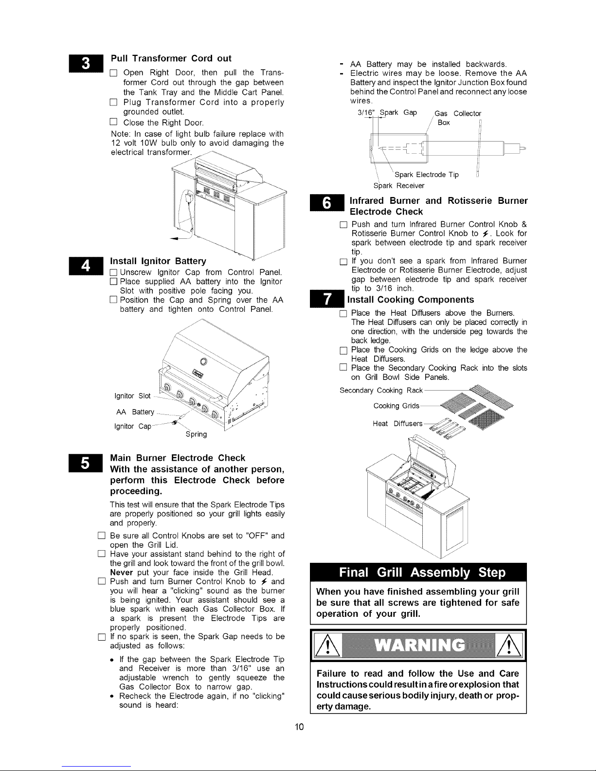
Pull Transformer Cord out
[] Open Right Door, then pull the Trans-
former Cord out through the gap between
the Tank Tray and the Middle Cart Panel.
[] Plug Transformer Cord into a properly
grounded outlet.
[] Close the Right Door.
Note: In case of light bulb failure replace with
12 volt 10W bulb only to avoid damaging the
electrical transformer.
Install Ignitor Battery
[] Unscrew Ignitor Cap from Control Panel.
[] Place supplied AA battery into the Ignitor
Slot with positive pole facing you.
[] Position the Cap and Spring over the AA
battery and tighten onto Control Panel.
":i
Ignitor Slot ' ".i
AA Battery _j
Ignitor Cap ............_\\
Spring
- AA Battery may be installed backwards.
Electric wires may be loose. Remove the AA
Battery and inspect the Ignitor Junction Box found
behind the Control Panel and reconnect any loose
wires.
3!16" _park Gap ,Gas Collector
/' Box
i
i 'Spark Electrode Tip
Spark Receiver
Infrared Burner and Rotisserie Burner
Electrode Check
[] Push and turn Infrared Burner Control Knob &
Rotisserie Burner Control Knob to _. Look for
spark between electrode tip and spark receiver
tip.
[] If you don't see a spark from Infrared Burner
Electrode or Rotisserie Burner Electrode, adjust
gap between electrode tip and spark receiver
tip to 3/16 inch.
Install Cooking Components
[] Place the Heat Diffusers above the Burners.
The Heat Diffusers can only be placed correctly in
one direction, with the underside peg towards the
back ledge.
[] Place the Cooking Grids on the ledge above the
Heat Diffusers.
[] Place the Secondary Cooking Rack into the slots
on Grill Bowl Side Panels.
Secondary Cooking Rack _
CookingGrids _ _
Heat Diffusers_;_ _
Main Burner Electrode Check
With the assistance of another person,
perform this Electrode Check before
proceeding.
This test will ensure that the Spark Electrode Tips
are properly positioned so your grill lights easily
and properly.
[] Be sure all Control Knobs are set to "OFF" and
open the Grill Lid.
[] Have your assistant stand behind to the right of
the grill and look toward the front of the grill bowl.
Never put your face inside the Grill Head.
[] Push and turn Burner Control Knob to _: and
you will hear a "clicking" sound as the burner
is being ignited. Your assistant should see a
blue spark within each Gas Collector Box. If
a spark is present the Electrode Tips are
properly positioned.
[] If no spark is seen, the Spark Gap needs to be
adjusted as follows:
• If the gap between the Spark Electrode Tip
and Receiver is more than 3/16" use an
adjustable wrench to gently squeeze the
Gas Collector Box to narrow gap.
• Recheck the Electrode again, if no "clicking"
sound is heard:
When you have finished assembling your grill
be sure that all screws are tightened for safe
operation of your grill.
Failure to read and follow the Use and Care
Instructions could result in a fire orexplosion that
could causeserious bodily injury, death or prop-
erty damage.
10
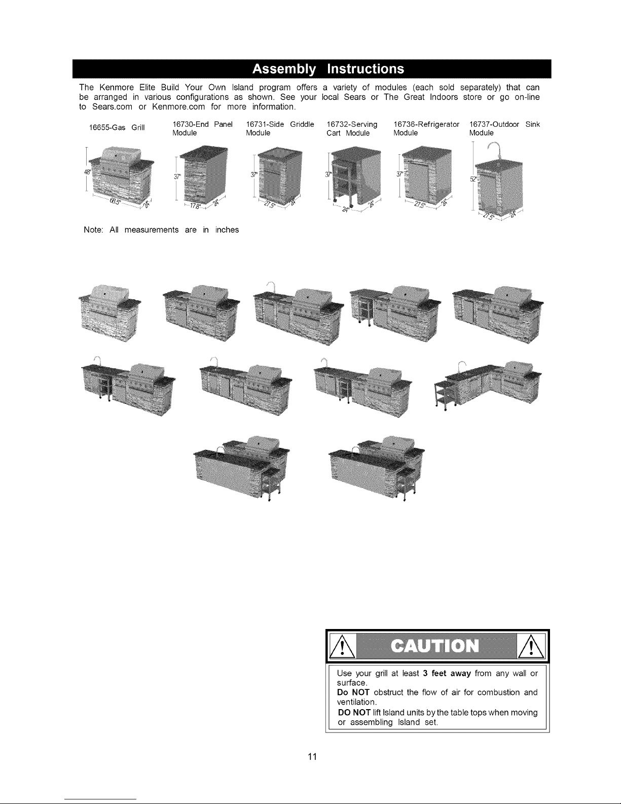
The Kenmore Elite Build Your Own Island program offers a variety of modules (each sold separately) that can
be arranged in various configurations as shown. See your local Sears or The Great Indoors store or go on-line
to Sears.com or Kenmore.com for more information.
16655-Gas Grill 16730-End Panel 16731-Side Griddle 16732-Serving 16736-Refrigerator 16737-Outdoor Sink
Module Module Cart Module Module Module
Note: All measurements are in inches
Jiiiijiiiiii_iiiiii[!iJii[!iijiJ
Use your grill at least 3 feet away from any wall or
surface.
Do NOT obstruct the flow of air for combustion and
ventilation.
DO NOT lift Island units by the table tops when moving
or assembling Island set.
11
CORRECT LP GAS TANK USE
[] LP Gas grill models are designed for use with a standard
20 lb. Liquid Propane Gas (LP Gas) tank, not included
with grill. Never connect your gas grill to an LP Gas tank
that exceeds this capacity. A tank of approximately 12
inches in diameter by 18-1/2 inches high is the maximum
size LP Gas tank to use. You must use an "OPD" gas
tank which offers a listed Overfill Prevention Device.
This safety feature prevents tank from being overfitled
which can cause malfunction of LP Gas tank, regulator
and/or grill.
[] The LP Gas tank must be constructed and marked in
accordance with the Specifications for LP-Gas Cylinders
of the U.S. Department of Transportation (D.O.T.) or the
National Standard of Canada, CAN/CSA-B339, Cylinders,
Spheres and Tubes for Transportation of Dangerous
Goods; and Commission, as applicable.
[] The LP Gas tank must have a shutoff valve, terminating
in an LP Gas supply tank valve outlet, that is compatible
with a Type 1 tank connection device. The LP Gas tank
must also have a safety relief device that has a direct
connection with the vapor space of the tank.
[] The tank supply system must be arranged for vapor
withdrawal.
[] The LP Gas tank used must have a collar to protect the
tank valve.
[] Never connect an unregulated LP gas tank to your gas
grill. The gas regulator assembly supplied with your gas
grill is adjusted to have an outlet pressure of 11" water
column (W.C.) for connection to an LP gas tank. Only use
the regulator and hose assembly supplied with your gas
grill. Replacement hose and regulator assembly must
be identical to those listed in the parts list of this Use
and Care Guide as specified by the Manufacturer.
[] Have your LP Gas dealer check the release valve after every
filling to ensure it remains free of defects.
[] Always keep LP Gas tank in upright position.
[] Do not subject the LP Gas tank to excessive heat.
[] Never store an LP Gas tank indoors. If you store your gas
grill in the garage always disconnect the LP Gas tank first
and store it safely outside.
[] LP Gas tanks must be stored outdoors in a well-ventilated
area and out of the reach of children.
[] Disconnected LP Gas tanks must not be stored in a building,
garage or any other enclosed area.
[] The regulator and hose assembly can be seen after opening
the doors (if applicable) and must be inspected before each
use of the grill. If there is excessive abrasion or wear or
if the hose is cut, it must be replaced prior to using the
grill again.
[] Any attempt to convert the grill from one fuel type to
another is extremely hazardous and must be per-
formed by a qualified gas technician only, using a NG
Conversion Kit purchased from Sears.
[] Never light your gas grill with the lid closed or before
checking to ensure the burner tubes are fully seated over
the gas valve orifices.
[] Never allow children to operate your grill. Do not allow
children or pets to play near your grill.
12
[] Use of alcohol, prescription or non-prescription drugs
can impair your ability to properly assemble and
safely operate your grill.
[] Keep fire extinguisher readily accessible. In the event
of a oil/grease fire, do not attempt to extinguish with
water. Use type B extinguisher or smother with dirt,
sand or baking soda.
[] In the event of rain, cover the grill and turn off the
burner and gas supply.
[] Use your grill on a level, stable surface in an area
clear of combustible materials.
[] Do not leave grill unattended when in use.
[] Do not move the appliance when in use.
[] Allow the grill to cool before moving or storing.
[] Do not use your grill as a heater.
[] This grill is not intended to be installed in or on
recreational vehicles and/or boats.
[] The grill is not intended for commercial use.
[] Never use charcoal in this gas grill.
A. Do not store a spare LP-Gas tank under or near
this appliance.
B. Never fill the tank beyond 80 percent full; and
C. If the information in "(a)" and "(b)" is not followed
exactly, a fire causing death or serious injury may
occur.
• Use your grill at least 3 feet away from any wall
or surface. Use your grill at least 3 feet away from
combustible objects that can melt or catch fire such
as vinyl or wood siding, fences and overhangs or
sources of ignition including pilot lights on water
heaters and live electrical appliances.
• Outdoor cooking gas appliance shall not be used
under overhead combustible construction.
• Never use your gas grill in a garage, porch, shed,
breezeway or any other enclosed area.
• Never obstruct the flow of ventilation air around your
gas grill housing.
• Inwindy conditions, always position the front of grill to
face oncoming wind to reduce smoke and heat blowing
in your face and prevent potential hazards to self and
grill.
NOTE about LP Gas Tank Exchange Programs
• Many retailers that sell grills offer you the option of
replacing your empty LP Gas tank through an exchange
service. Use only those reputable exchange compa-
nies that inspect, precision fill, test and certify their
tanks. Exchange your tank only for an OPD safety fea-
ture-equipped tank as described in the LP Gas tank
section of this guide.
• Always keep new and exchanged LP Gas tanks in an up-
right position during use, transit or storage.
• Leak test new and exchanged LP Gas tanks BEFORE
connecting one to your grill.
How to Leak Test your LP Gas Tank
For your safety:
All leak tests must be repeated each time your LP
Gas tank is exchanged or refilled.
When checking for gas leaks do not smoke.
Do not use an open flame to check for gas leaks.
Your grill must be leak tested outdoors in a well-ven-
tilated area, away from ignition sources such as gas
fired or electrical appliances. During the leak test, keep
your grill away from open flames or sparks.
Do not use household cleaning agents. Damage to
gas assembly components can result.
[] Use a clean paintbrush and a 50/50 mild soap and
water solution.
[] Brush soapy solution onto LP Gas tank in the ar-
eas indicated by the arrows. See diagram.
[] If growing bubbles appear do not use or move the
LP Gas tank. Call an LP Gas Supplier or your Fire
Department.
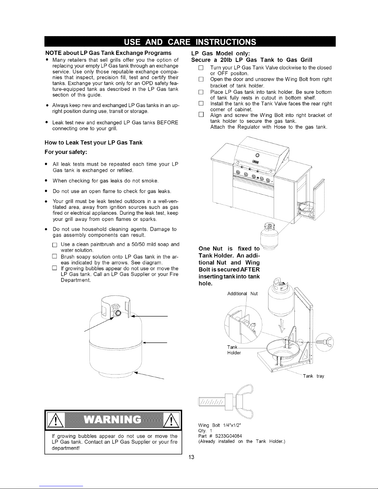
LP Gas Model only:
Secure a 201b LP Gas Tank to Gas Grill
[] Turn your LP Gas Tank Valve clockwise to the closed
or OFF positon.
[] Open the door and unscrew the Wing Bolt from right
bracket of tank holder.
[] Place LP Gas tank into tank holder. Be sure bottom
of tank fully rests in cutout in bottom shelf.
[] Install the tank so the Tank Valve faces the rear right
corner of cabinet.
[] Align and screw the Wing Bolt into right bracket of
tank holder to secure the gas tank.
Attach the Regulator with Hose to the gas tank.
!
One Nut is fixed to
Tank Holder. An addi-
tional Nut and Wing
Bolt is secured AFTER
inserting tank into tank
hole.
Additional Nut
J
__-._ ....__.I _
/
If growing bubbles appear do not use or move the
LP Gas tank. Contact an LP Gas Supplier or your fire
department!
Tank
Holder
Wing Bolt 1!4"xl/2"
Qty. 1
Part # S233G04084
(Already installed on the Tank Holder.)
13
Tank tray
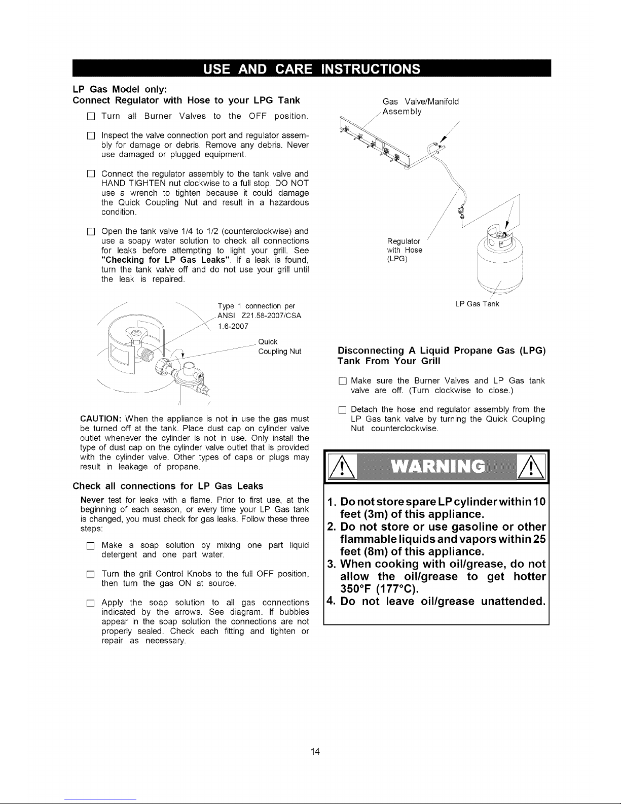
LP Gas Model only:
Connect Regulator with Hose to your LPG Tank
[] Turn all Burner Valves to the OFF position.
[] Inspect the valve connection port and regulator assem-
bly for damage or debris. Remove any debris. Never
use damaged or plugged equipment.
[]
Connect the regulator assembly to the tank valve and
HAND TIGHTEN nut clockwise to a full stop. DO NOT
use a wrench to tighten because it could damage
the Quick Coupling Nut and result in a hazardous
condition.
[]
Open the tank valve 1/4 to 1/2 (counterclockwise) and
use a soapy water solution to check all connections
for leaks before attempting to light your grill. See
"Checking for LP Gas Leaks". If a leak is found,
turn the tank valve off and do not use your grill until
the leak is repaired.
j/f
- ..... Type 1 connection per
_ _ANSl Z21.58-2007/CSA
1.6-2007
Quick
..................CouplingNut
\
CAUTION: When the appliance is not in use the gas must
be turned off at the tank. Place dust cap on cylinder valve
outlet whenever the cylinder is not in use. Only install the
type of dust cap on the cylinder valve outlet that is provided
with the cylinder valve. Other types of caps or plugs may
result in leakage of propane.
Check all connections for LP Gas Leaks
Never test for leaks with a flame. Prior to first use, at the
beginning of each season, or every time your LP Gas tank
is changed, you must check for gas leaks. Follow these three
steps:
[] Make a soap solution by mixing one part liquid
detergent and one part water.
[] Turn the grill Control Knobs to the full OFF position,
then turn the gas ON at source.
[] Apply the soap solution to all gas connections
indicated by the arrows. See diagram. If bubbles
appear in the soap solution the connections are not
properly sealed. Check each fitting and tighten or
repair as necessary.
Gas Valve/Manifold
/Assembly
Regulator /
with Hose
(LPG)
LP Gas Tank
Disconnecting A Liquid Propane Gas (LPG)
Tank From Your Grill
[] Make sure the Burner Valves and LP Gas tank
valve are off. (Turn clockwise to close.)
[] Detach the hose and regulator assembly from the
LP Gas tank valve by turning the Quick Coupling
Nut counterclockwise.
1. Do not store spare LP cylinderwithin 10
feet (3m) of this appliance.
2. Do not store or use gasoline or other
flammable liquids and vapors within 25
feet (8m) of this appliance.
3. When cooking with oil/grease, do not
allow the oil/grease to get hotter
350°F (177°C).
4. Do not leave oil/grease unattended.
14
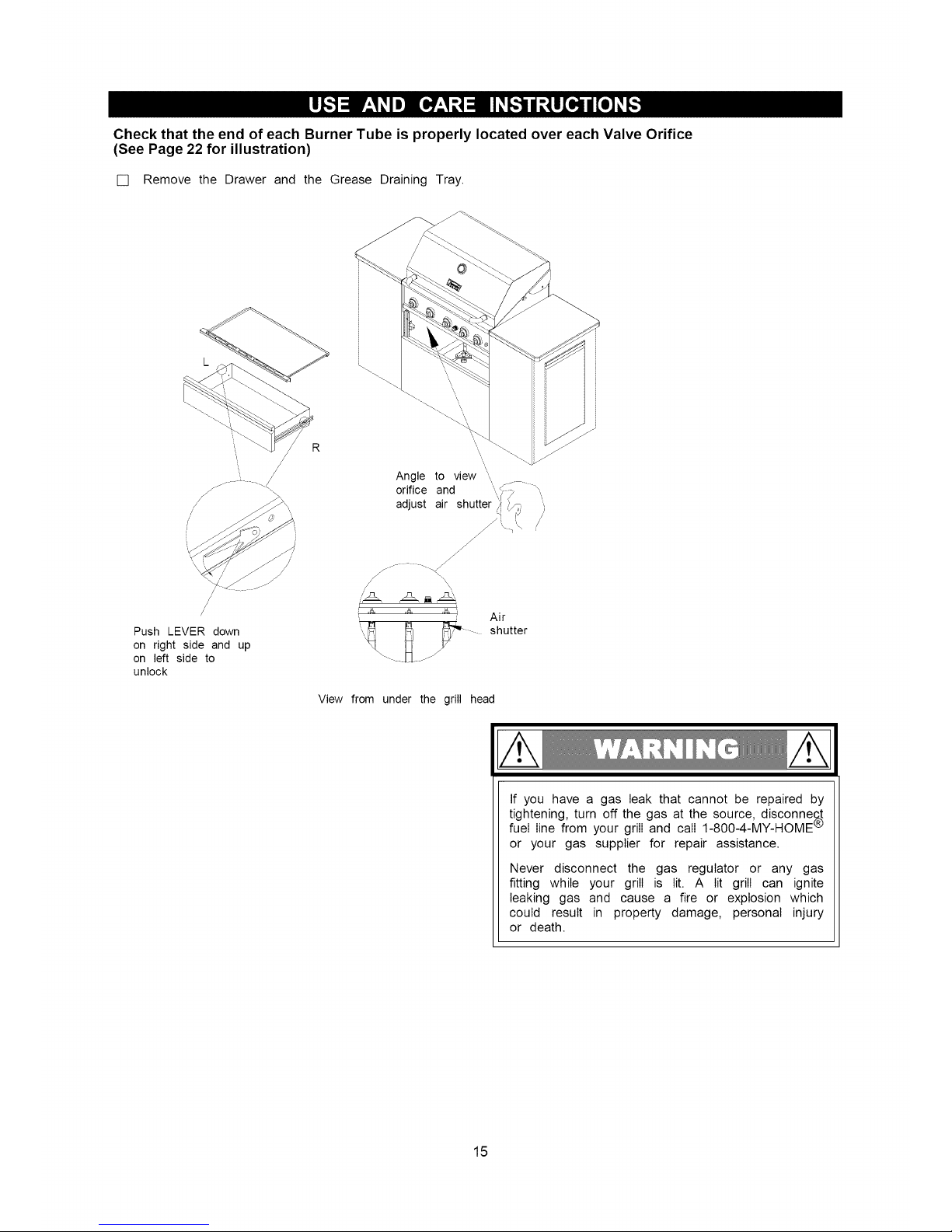
Check that the end of each Burner Tube is properly located over each Valve Orifice
(See Page 22 for illustration)
[] Remove the Drawer and the Grease Draining Tray.
Push LEVER down
on right side and up
on left side to
unlock
R
Angle to view '
orifice and \,
adjust air shutter
J
y ./
/
Air
shutter
View from under the grill head
If you have a gas leak that cannot be repaired by
tightening, turn off the gas at the source, disconne_
fuel line from your grill and call 1-800-4-MY-HOME '_
or your gas supplier for repair assistance.
Never disconnect the gas regulator or any gas
fitting while your grill is lit. A lit grill can ignite
leaking gas and cause a fire or explosion which
could result in property damage, personal injury
or death.
15
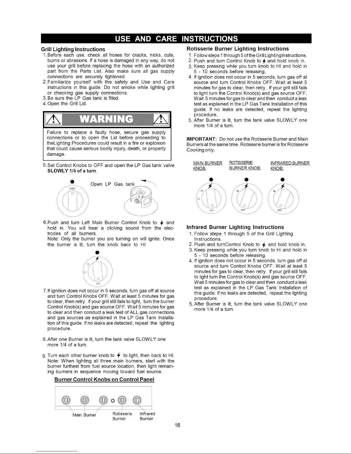
Grill Lighting Instructions
1.Before each use, check all hoses for cracks, nicks, cuts,
burns or abrasions. If a hose is damaged in any way, do not
use your grill before replacing the hose with an authorized
part from the Parts List. Also make sure all gas supply
connections are securely tightened.
2.Familiarize yourself with the safety and Use and Care
instructions in this guide. Do not smoke while lighting grill
or checking gas supply connections.
3.Be sure the LP Gas tank is filled.
4.Open the Grill Lid.
Failure to replace a faulty hose, secure gas supply
connections or to open the Lid before proceeding to
theLighting Procedures could result in a fire or explosion
that could cause serious bodily injury, death, or property
damage.
5.Set Control Knobs to OFF and open the LP Gas tank valve
SLOWLY 1/4 of a turn.
Rotisserie Burner Lighting Instructions
1. Follow steps 1through 5 ofthe GrillLightinglnstructions.
2. Push and turn Control Knob to _ and hold knob in.
3. Keep pressing while you turn knob to HI and hold in
5 - 10 seconds before releasing.
4. If ignition does not occur in 5 seconds, turn gas off at
source and turn Control Knobs OFF. Wait at least 5
minutes for gas to clear, then retry. If your grill still fails
to light turn the Control Knob(s) and gas source OFF.
Wait 5 minutes for gas to clear and then conduct a leak
test as explained in the LP Gas Tank Installation of this
guide. If no leaks are detected, repeat the lighting
procedure.
5. After Burner is lit, turn the tank valve SLOWLY one
more 1/4 of a turn.
IMPORTANT: Do not use the Rotisserie Burner and Main
Burners at the same time. Rotisserie burner isfor Rotisserie
Cooking only.
MAIN BURNER ROTISSERIE INFRARED BURNER
KNOB: BURNER KNOB: KNOB:
• Open LP Gas tank
[\
6.Push and turn Left Main Burner Control Knob to _r and
hold in. You will hear a clicking sound from the elec-
trodes of all burners.
Note: Only the burner you are turning on will ignite. Once
the burner is lit, turn the knob back to HI.
7. If ignition does not occur in 5 seconds, turn gas off at source
and turn Control Knobs OFF. Wait at least 5 minutes for gas
to clear, then retry. Ifyour grill stillfails to light, turn the burner
Control Knob(s) and gas source OFF. Wait 5 minutes for gas
to clear and then conduct a leak test of ALL gas connections
and gas sources as explained in the LP Gas Tank Installa-
tion of this guide. If no leaks are detected, repeat the lighting
procedure.
//' i
Infrared Burner Lighting Instructions
1. Follow steps 1 through 5 of the Grill Lighting
Instructions.
2. Push and turnControI Knob to _, and hold knob in.
3. Keep pressing while you turn knob to Hi and hold in
5 - 10 seconds before releasing.
4. If ignition does not occur in 5 seconds, turn gas off at
source and turn Control Knobs OFF. Wait at least 5
minutes for gas to clear, then retry. Ifyour grill still fails
to light turn the Control Knob(s) and gas source OFF.
Wait 5 minutes for gas to clear and then conduct a leak
test as explained in the LP Gas Tank Installation of
this guide. Ifno leaks are detected, repeat the lighting
procedure.
5. After Burner is lit, turn the tank valve SLOWLY one
more 1/4 of a turn.
8.After one Burner is lit, turn the tank valve SLOWLY one
more 1/4 of a turn.
9. Turn each other burner knob to _, to light, then back to HI.
Note: When lighting all three main burners, start with the
burner furthest from fuel source location, then light remain-
ing burners in sequence moving toward fuel source.
Burner Control Knobs on Control Panel
/_ Rotsser e nfrared
Main Burner
Burner Burner
16

Manually Lighting Your Grill By Paper Match
To light your gas grill by match, insert a match into the Lighting
Stick and follow steps 1 through 5 of the Grill Lighting
Instructions. Then, light the match and place Lighting Stick
through the Cooking Grid on the grill as shown below. Turn
the nearest Control Knob to the HI setting to release gas. The
Burner should light immediately.
Match
'\
\
\
\
\
Lighting
Stick
(Note: the Lighting Stick is placed in the drawer.)
Never lean over the grill cooking area while lighting
your gas grill. Keep your face and body a safe distance
(at least 18 inches) from the front of grill when lighting
your grill by match.
Should a FLASHBACK fire occur in or around the
Burner Tubes, follow the instructions below. Failure
to comply with these instructions could result in a
fire or explosion that could cause serious bodily
injury, death, or property damage.
• Shut off gas supply to the gas grill.
• Turn the Control Knobs to OFF position.
• Open the Grill Lid.
• Put out any flame with a Class B fire
extinguisher.
• Once the grill has cooled down, clean the
Burner Tubes and Burners according to the
cleaning instructions in this Use and Care
Guide.
If ignition does not occur in 5 seconds, turn the Control
Knob(s) and gas source OFF and conduct a leak test
as explained in the Use and Care section of this guide.
If no leaks are detected, wait 5 minutes for any gas
to clear and repeat the lighting procedure.
To
the
[]
[]
[]
[]
[]
[]
[]
[]
[]
17
Troubleshooting
If the grill fails to light :
1. Turn gas offat source and turn Control Knobs to OFF. Wait
at least 5 minutes for gas to clear, then retry.
2. If your grill still fails to light, check gas supply and
connections.
3. Repeat lighting procedure. If your grill still fails to oper-
ate, turn the gas off at source, turn the Control Knobs to
OFF, then check the following:
[] Misalignment of Burner Tubes over Orifices
Correction: Reposition Burner Tubes over Orifices.
[] Obstruction in gas line
Correction: Remove fuel line from grill. Do not smoke! Open
gas supply for one second to clear any obstruction from fuel
line. Close off gas supply at source and reconnect fuel line
to grill.
[] Plugged Orifice
Correction: Remove Burners from grill by removing the
screw from the rear of each Burner using Phillips Head
Screwdriver. Carefully lift each Burner up and away from
gas valve Orifice. Remove the Orifice from gas valve and
gently clear any obstruction with a fine wire. Then reinstall
all Orifices, Burners, screws and cooking components.
[] If an obstruction is suspected in Gas Valves or Manifold,
call the Grill Information Center 1-888-317-7642 8am to
8pm CST, Monday through Friday.
[] Obstruction in Burner Tubes
Correction: Follow the Burner Tube cleaning procedure on
page 22 of this Use and Care Guide.
[] Misalignment of Ignitor on Burner
Correction: Check for proper position of the Electrode Tip
as shown in steps 5 & 6 on page 10. The gap between
the Spark Electrode Tip and Spark Receiver should be
approximately 3/16". Adjust if necessary. With the gas
supply closed, turn any Main Burner Control Knob _, to
then push in and watch for the presence of a spark at the
Electrode.
[] Disconnected Electric Wires
Correction: Inspectthe Ignitor Junction Boxfound behind the
Control Panel. Connect loose Electric wires to Junction Box
and try to light the grill.
[] WeakAA battery
Correction: Unscrew the Ignitor Cap and replace the bat-
tery.
[] If the grill still does not light you may need to purge
air from the gas line or reset the regulator excess gas
flow device. Note: This procedure should be done every
time a new LP Gas tank is connected to your grill.
purge air from your gas line and/or reset
regulator excess gas flow device:
Turn Control Knobs to the OFF position.
Turn off the gas at the tank valve.
Disconnect regulator from LP Gas tank.
Let unit stand 5 minutes to allow air to purge.
Reconnect regulator to the LP Gas tank.
Turn tank valve on SLOWLY 1/4 of a turn.
Open the Grill Lid.
Push and
to _, and
burner is
turn the Left Main Burner Control Knob
you will hear a clicking sound as the
being ignited.
Once the burner is lit, turn the knob back to HI.
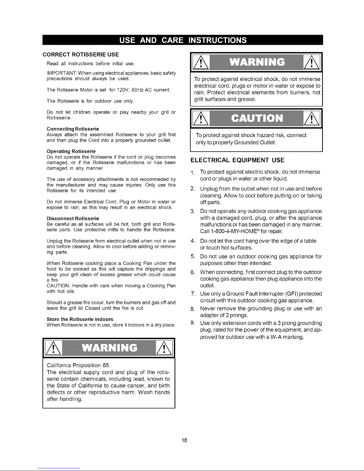
CORRECT ROTISSERIE USE
Read all instructions before initial use.
IMPORTANT: When using electrical appliances, basic safety
precautions should always be used.
The Rotisserie Motor is set for 120V, 60Hz AC current.
The Rotisserie is for outdoor use only.
Do not let children operate or play nearby your grill or
Rotisserie.
Connecting Rotisserie
Always attach the assembled Rotisserie to your grill first
and then plug the Cord into a properly grounded outlet.
Operating Rotisserie
Do not operate the Rotisserie if the cord or plug becomes
damaged, or if the Rotisserie malfunctions or has been
damaged in any manner.
The use of accessory attachments is not recommeded by
the manufacturer and may cause injuries. Only use this
Rotisserie for its intended use.
Do not immerse Electrical Cord, Plug or Motor in water or
expose to rain, as this may result in an electrical shock.
Disconnect Rotisserie
Be careful as all surfaces will be hot, both grill and Rotis-
serie parts. Use protective mitts to handle the Rotisserie.
Unplug the Rotisserie from electrical outlet when not in use
and before cleaning. Allow to cool before adding or remov-
ing parts.
When Roitsserie cooking place a Cooking Pan under the
food to be cooked as this will capture the drippings and
keep your grill clean of excess grease which could cause
a fire.
CAUTION: Handle with care when moving a Cooking Pan
with hot oils
Should a grease fire occur, turn the burners and gas off and
leave the grill lid Closed until the fire is out.
Store the Rotisserie indoors
When Rotisserie is not in use, store it indoors in a dry place.
To protect against electrical shock, do not immerse
electrical cord, plugs or motor in water or expose to
rain. Protect electrical elements from burners, hot
grill surfaces and grease.
To protect against shock hazard risk, connect
only to properly Grounded Outlet.
ELECTRICAL EQUIPMENT USE
, To protect against electric shock, do not immerse
cord or plugs in water or other liquid.
2. Unplug from the outlet when not in use and before
cleaning. Allow to cool before putting on or taking
off parts.
3. Do not operate any outdoor cooking gas appliance
with a damaged cord, plug, or after the appliance
malfunctions or has been damaged in any manner.
Call 1-800-4-MY-HOME ®for repair.
,
5.
,
Do not let the cord hang over the edge of a table
or touch hot surfaces.
Do not use an outdoor cooking gas appliance for
purposes other than intended.
When connecting, first connect plug to the outdoor
cooking gas appliance then plug appliance into the
outlet.
7. Use only a Ground Fault Interrupter (GFI) protected
circuit with this outdoor cooking gas appliance.
8. Never remove the grounding plug or use with an
adapter of 2 prongs.
9. Use only extension cords with a 3 prong grounding
plug, rated for the power of the equipment, and ap-
proved for outdoor use with a W-A marking.
California Proposition 65
The electrical supply cord and plug of the rotis-
serie contain chemicals, including lead, known to
the State of California to cause cancer, and birth
defects or other reproductive harm. Wash hands
after handling.
18
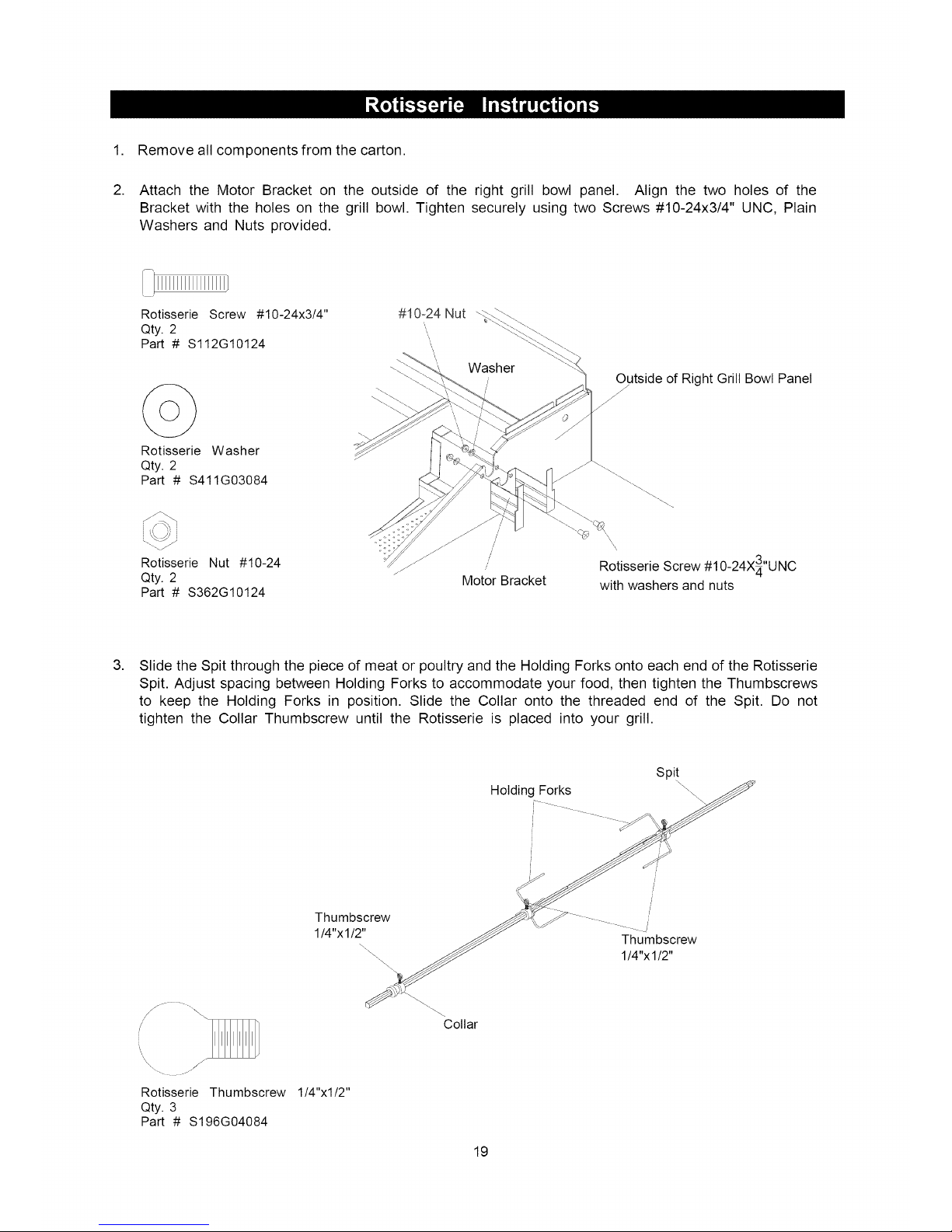
1. Removeallcomponentsfromthecarton.
2. Attachthe MotorBracketon the outsideof the rightgrill bowlpanel. Alignthetwo holesof the
Bracketwiththeholeson thegrill bowl.TightensecurelyusingtwoScrews#10-24x3/4"UNC,Plain
WashersandNutsprovided.
i[1111111111111111
Rotisserie Screw #10-24x3/4" #10-24 Nut
Qty. 2
Part # S112G10124 ",,
,\
Rotisserie Washer
Qty. 2
Part # S411G03084
Rotisserie Nut #10-24
Qty. 2
Part # S362G10124
J
Outside of Right Grill Bowl Panel
/
f
f
f
Motor Bracket
/ \\
' X
/
J Rotisserie Screw #10-24X3"UNC
with washers and nuts
,
Slide the Spit through the piece of meat or poultry and the Holding Forks onto each end of the Rotisserie
Spit. Adjust spacing between Holding Forks to accommodate your food, then tighten the Thumbscrews
to keep the Holding Forks in position. Slide the Collar onto the threaded end of the Spit. Do not
tighten the Collar Thumbscrew until the Rotisserie is placed into your grill.
Holding Forks
J
Spit
Thumbscrew
1/4"x1/2"
Thumbscrew
1/4"x1/2"
Rotisserie Thumbscrew 1/4"xl/2"
Qty. 3
Part # S196G04084
"Collar
19
 Loading...