

Kenmore 141.156400, Elite 141.156400 Owner's Manual
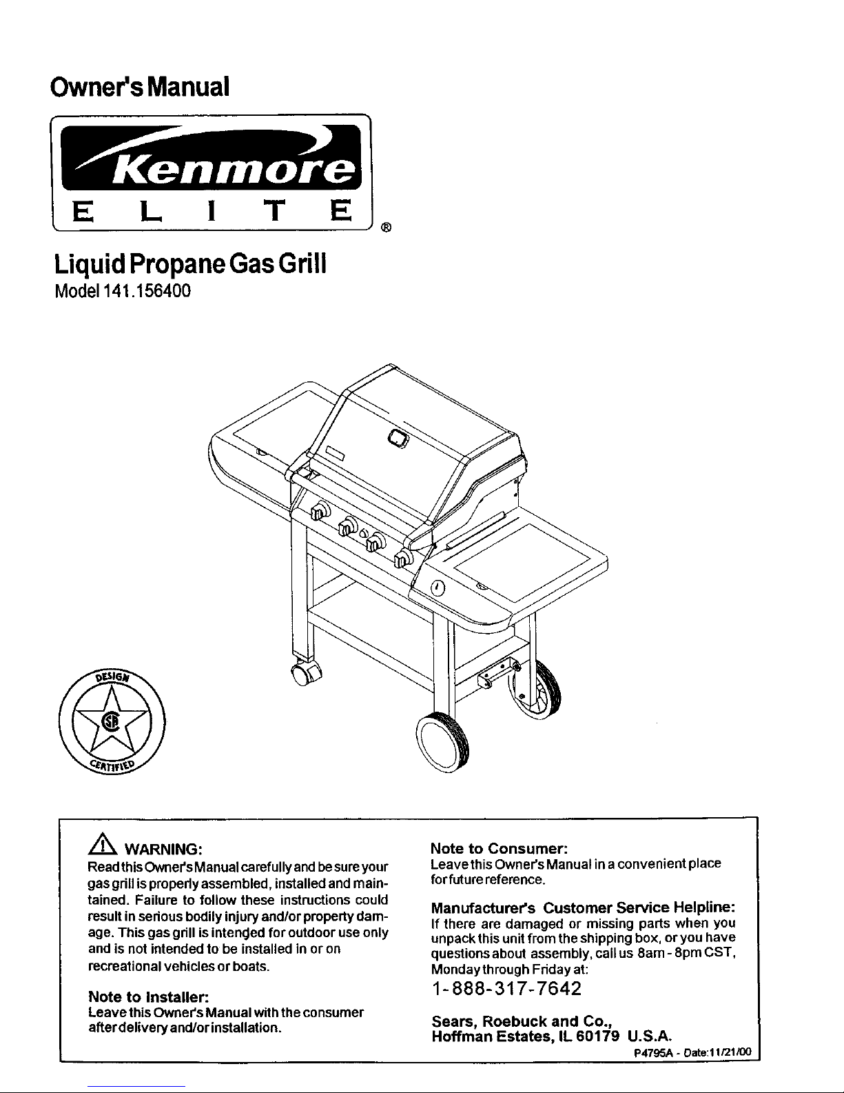
Owner'sManual
E L I T E
LiquidPropaneGasGrill
Model141.156400
®
Z_ WARNING:
Readthis Owner'sManual carefully andbesure your
gas grillispropedy assembled, installed and main-
tained. Failure to follow these instructions could
resultin sedous bodily injuryand/or propertydam-
age. This gas gdll is intencJedfor outdoor use only
and is not intended to be installed in or on
recreational vehicles or boats.
Note to Installer:
Leave this Owner's Manual withtheconsumer
afterdelivery and/or installation.
Note to Consumer:
Leavethis Owner's Manual in a convenient place
for futurereference.
Manufacturer's Customer Service Helpline:
If there are damaged or missing parts when you
unpackthis unit from the shipping box, oryou have
questions about assembly, callus 8am - 8pm CST,
Mondaythrough Fdday at:
1-888-317-7642
Sears, Roebuck and Co.,
Hoffman Estates, IL60179 U.S.A.
P4795A - Date:l 1/21/00
Warranty ..................................................... 2
Safety Instructions .................................... 2
Pre-Assembly Instructions ......................... 4
Hardware, Parts Diagram and Lists ..... 5
Assembly Instructions ................................. 8
lighting Instructions .................................. 13
Cleaning and Maintenance Instructions .... 15
Frequently Asked Questions .................. 17
Cooking Instructions ................................ 18
Cooking Guide and Recipes ................ 24
Full l-Year Warranty on Grill
For one year from the date of purchase Sears will
repair or replace, at our option, any grill part
(except for paint loss and ignitor battery) that is
defective in material or workmanship.
Limited Warranty on Selected Grill Parts
From one year after the date of purchase for the
designated time periods listed below, Sears will
replace the following gdll parts if they are defective
in material or workmanship. You will be charged
for labor.
• Lifetime of Grill: Exterior Stainless Steel Parts,
Aluminum Castings (except for paint loss)
• 2 Years: Flame Tamers, Cooking Gnds, Burners
• 4 Years: All Other Grill Parts (except ignitorbattery)
Warranty Service
Warranty service is available by contacting your
nearest Sears Service Center.
Warranty Restrictions
• This warranty is void if grill is used for commer-
cial or rental purposes.
• This warranty applies only when the grill is
used in the United States.
• This warranty gives you specific legal dghts,
and you may also have other rights which vary
from state to state.
Sears, Roebuck and Co., Dept. 817WA,
Hoffman Estates, IL 60179
Z_WARNING
Combustion by-products produced when
using this product contain chemicals known
to the State of California to cause cancer,
birth defects, or other reproductive harm.
Z_WARNING
Failure to comply with these instructions
could result in a fire or explosion that
could cause serious bodily injury, death,
or property damage.
Grill Installation Codes
This gas grill must be installed in accordance with
all local codes. In areas without local codes,
follow the latest edition of the National Fuel Gas
Code ANSI Z223.1. In Canada, installation must
conform to standard CAN/CGA lb149.1 or 1-
b149.2 (Installation Code for Gas Burning Appli-
ances and Equipment) and all local codes.
Correct LP Gas Tank Use
LP gas gnll models are designed for use with a
standard 20 lb. Liquid Propane Gas (LP gas)
tank; not included with gdll box.. Never connect
your gas gdll to an LP gas.tank that exceeds
this capacity: A tank of approximately 12 inches
in diameter by 18-1/2 inches high is the maxi-
mum size LP gas tank to use. We recommend
buying an "OPD" gas tank which offers an Overfill
Prevention Device. This safety feature prevents the
tank from being overfilled which can cause mal-
function of the LP gas tank, regulator and/or gdll.
The LP gas tank must be constructed and
marked in accordance with specifications of the
U.S. Dept. of Transportation (DOT). In Canada, the
LP gas tank must meet the Canadian Transpoda-
tion and Communications (CTC)
specifications. Also be sure:
1. The LP gas tank has a shutoff valve, termi-
nating in an LP gas supply tank valve outlet,
that is compatible with a Type 1 tank con-
nection device. The LP gas tank must also
have a safety relief device that has a direct
communication with the vapor space of the
tank.
2. The tank supply system must be arranged for
vapor withdrawal.
3. The LP gas tank used must have a collar
to protect the tank valve.
2 Sears, Roebuck and Co.

ProperPlacementand Clearanceof Grill
Neveruseyourgasgrillinagarage,porch,shed,
breezewayoranyotherenclosedarea.Yourgasgrillis
tobeusedoutdoorsonly,atleast24inchesfromthe
backandsideof anycombustiblesurface.Your
gas grill should not be placed under any surface
that will bum. Do not obstruct the flow of ventilation
air around the gas grill housing.
This outdoor gas grill isnot intended to be installed in
or on recreational vehicles and/or boats.
WARNING
Failure to comply with these instructions
could result in a fire or explosion that
could cause serious bodily injury, death,
or property damage.
• Never connect an unregulated LP gas tank to
your gas grill. The gas regulator assembly
supplied with your gas grill is adjusted to have
an outlet pressure of 11" water column (W.C.)
for connection to an LP gas tank.
• Only use the regulator and hose assembly
supplied with your gas grill. Replacement
regulators and hose assemblies must be those
specified by Sears.
• Have your LP gas tank filled by a reputable
propane gas dealer and visually inspected and
re-qualified at each filling.
• Never fill the gas tank beyond 80% full.
Have your propane gas dealer check the
release valve after every filling to ensure that it
remains free of defects.
• Always keep LP gas tanks in an upright
position.
• Do not store (or use) gasoline orother flammable
vapors and liquids in the vicinity of this gas grill.
• An LP gas tank that is not connected for use must
not be stored in the vicinity of this or any other gas
grill.
• Do not subject the LP gas tank to excessive heat.
• Never store an LP gas tank indoors. If you
store your gas gdll in the garage or other indoor
location, always disconnect the LP gas tank
first and store it safely outside.
• LP gas tanks must be stored outdoors in a
well-ventilated area. Disconnected LP gas tanks
must not be stored in a building, garage or
any other enclosed area.
• When your gas grill is not in use the gas
must be turned off at the LP gas tank.
• The regulator and hose assembly must be
inspected before each use of the grill. If there
is excessive abrasion or wear or if the hose is
cut, it must be replaced prior to the grill being
used again.
• Keep the gas regulator hose away from
hot grill surfaces and dripping grease.
Avoid unnecessary twisting of hose. Visually
inspect hose prior to each use for cuts,
cracks, excessive wear or other damage.
If the hose appears damaged do not use the
gas grill. Call Sears at 1-8O0-4-MY-HOME for
a Sears authorized replacement hose.
• Never light your gas grill with the lid closed
or before checking to insure the burner tubes
are fully seated over the gas valve orifices.
• Never allow children to operate your gdll. Do
not allow children to play near your grill
AkWARNING
A strong gas smell, or the hissing sound of
gas indicates a serious problem with your
gas grill or the LP gas tank. Failure to
immediately follow the steps listed below
could result in a fire or explosion that could
cause serious bodily injury, death, or prop-
erty damage.
• Shut off gas supply to the gas grill.
• Turn the control knobs to OFF position.
• Put out any flame with a fire extinguisher.
• Open grill lid.
• Get away from the LP gas tank.
• Do not try to fix the problem yourself.
• If odor continues or you have a fire you
cannot extinquish, call your fire department.
Do not call near the LP gas tank because
your telephone is an electrical device and
could create a spark resulting in fire and/or
explosion.
3
CAUTION: Spiders and small insects occa-
sionally spin webs or make nests in the
grill burner tubes during transit and ware-
housing. These webs can lead to a gas flow
obstruction which could result in a fire in
and around the burner tubes, This type of
fire is known as a "FLASH-BACK" and can
cause serious damage to your grill and
create an unsafe operating condition for the
user.
Although an obstructed burner tube is not
the only cause of "FLASH-BACK", it is the
most common cause.
To reduce the chance of "FLASH-BACK",
you must clean the burner tubes before
assembling your gdll, and at least once a
month in late summer or early fall when
spiders are most active. Also perform this
burner tube cleaning procedure if your grill
has not been used for an extended period
of time.

To reduce the chance of "FLASH-BACK" (see
CAUTION on page 3) clean the burner tubes and
burners before fully assembling your gdll. Remove
the cotter pin from the rear underside of each
burner using a pair of long nose pliers. Carefully
lift each burner up and away from the gas valve
odfice, then refer to Figure 1 and perform one of
these three cleaning methods:
1. Bend a stiff wire, (a lightweight coat hanger
works well) into a small hook as shown below.
Run the hook through the burner tube and
inside the burner several times to remove any
debds.
{ '1)
2. Use a bottle brush with a flexible handle. Run
the brush through the burner tube and inside
the burner several times, removing any debris.
3. Use an air hose to force air through each
burner tube. The forced air should pass debris
or obstructions through the burner and out the
pods.
Z WARNING
The location of the burner tube with respect
to the orifice is vital for safe operation.
Check to ensure the edfice is inside of the
burner tube before using your gas gdll. See
Fig. 2. If the burner tube does not fit over
the valve Ddfice, lighting the burner may
cause explosion and/or fire.
Figure 2
GAS VALVE ASSEMBLY
ORIFICE
BURNER TUBE
Figure 1
TO CLEAN BURNER TUBE,
INSERT HOOK HERE
SPARK ELECTRODE
ASSEMBLY
/
BURNER TUBE
GAS COLLECTOR BOX
¢o.......i? ;iiooi ;iio oll
COTTER PIN
• Size 2 phillips screwdriver
• Size 4 phillips screwdriver
• Adjustable wrench
• Long nose pliers
• Open-end wrench, 11116" size
• Protective work gloves
• Eye protection
4

The following table illustrates a breakdown of the hardware pack. It highlights what components are used
in the various stages of assembly.
Ref.
HO05
H001
H002
H003
H005
H005
H005
H005
H012
H009
H004
H015
H008
H013
H014
P8080A
Component Qty. to
1/4"x1/2" Phillips Head Screw 4
3/8" Wheel Bolt 2
Spdng Washer 2
3/8" Nut 2
1/4"x1/2" Phillips Head Screw 8
1/4"x1/2" Phillips Head Screw 4
114"x112"Phillips Head Screw 2
1/4"x1/2" Phillips Head Screw 2
1/4"xl-3/8" Phillips Head Screw 4
1/4" Lock Nut 4
1/4"x3/4" Phillips Head Screw 8
M6 Phillips Head Screw 2
M6 Nut 2
M18xl.5 Nut 1
M8x1.25 Nut 1
AA Battery 1
Use
Purpose of Components
Install Bottom Shelf To Cart Legs
Install Wheels To Cart Legs
Install The Two Braces To Cart
Restdct Drawer From Being Pulled Out Too Far
Install Pressure Cylinder Holder To Cart
Install Tank Guide To Cart
Install Grill Head To Cart
Install Side Shelves To Cart
Install Tool Holder To Side Shelf
Install Pressure Cylinder To Holder
Install Tank Hook To Pressure Cylinder
Install To Electric Ignitor
Actual Size and Quantity of Each Hardware Piece:
3/8" Wheel Bolt
Qty. 2
Ref. # HO01
©
SpringWasher
Qty. 2
Ref. # HO02
1/4"x3/4" Phillips
Head Screw
Qty. 8
Ref, # HO04
1/4"xli'Z' Phillips
Head Screw
Qty. 20
Ref. # H005
AA Battery
Qty. 1
Part # P8080A
M6 Phillips Head Screw
Qty. 2
Ref. # HO15(packed w_th Tool Holder)
1/4"xl-3/8" Phillips Head Screw
Qty. 4
Ref, # H012
M18x1+5 Nut Qty. 1
Ref+ #
HO13(attached to
Pressure Cylinder)
©
MSx1.25 Nut Qty. 1
Ref. # HO14(attached
to Pressure cylinder)
©
3/8" Nut
Qty.2
Ref. # H003
©
114" Lock Nut
Qty. 4
Ref. # H009
©
M6 Nut
Qty. 2
Ref, # HOOS(packed
with Tool Holder)
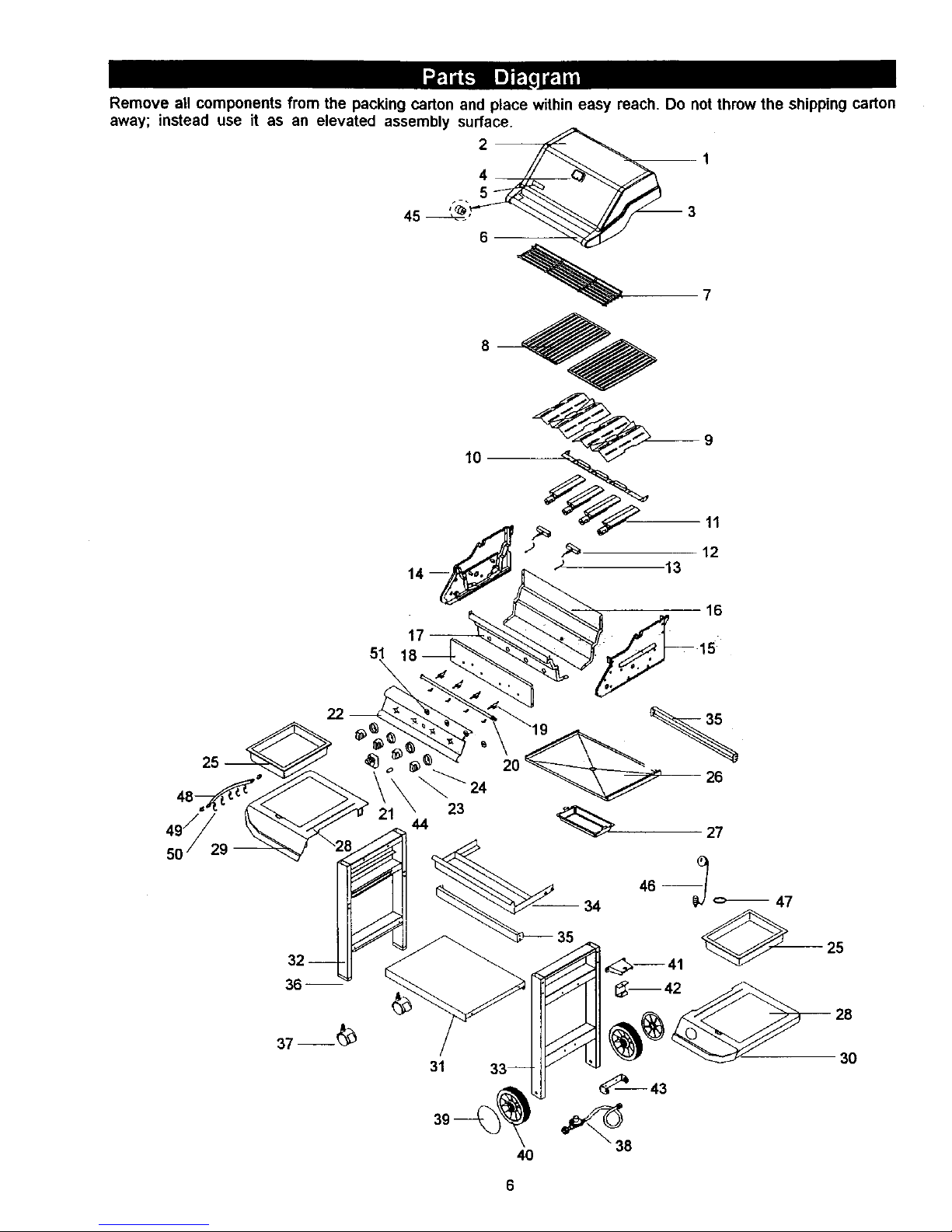
Remove all components from the packing carton and place within easy reach. Do not throw the shipping carton
away; instead use it as an elevated assembly surface.
45 _" 3
51
16
47
3O
6
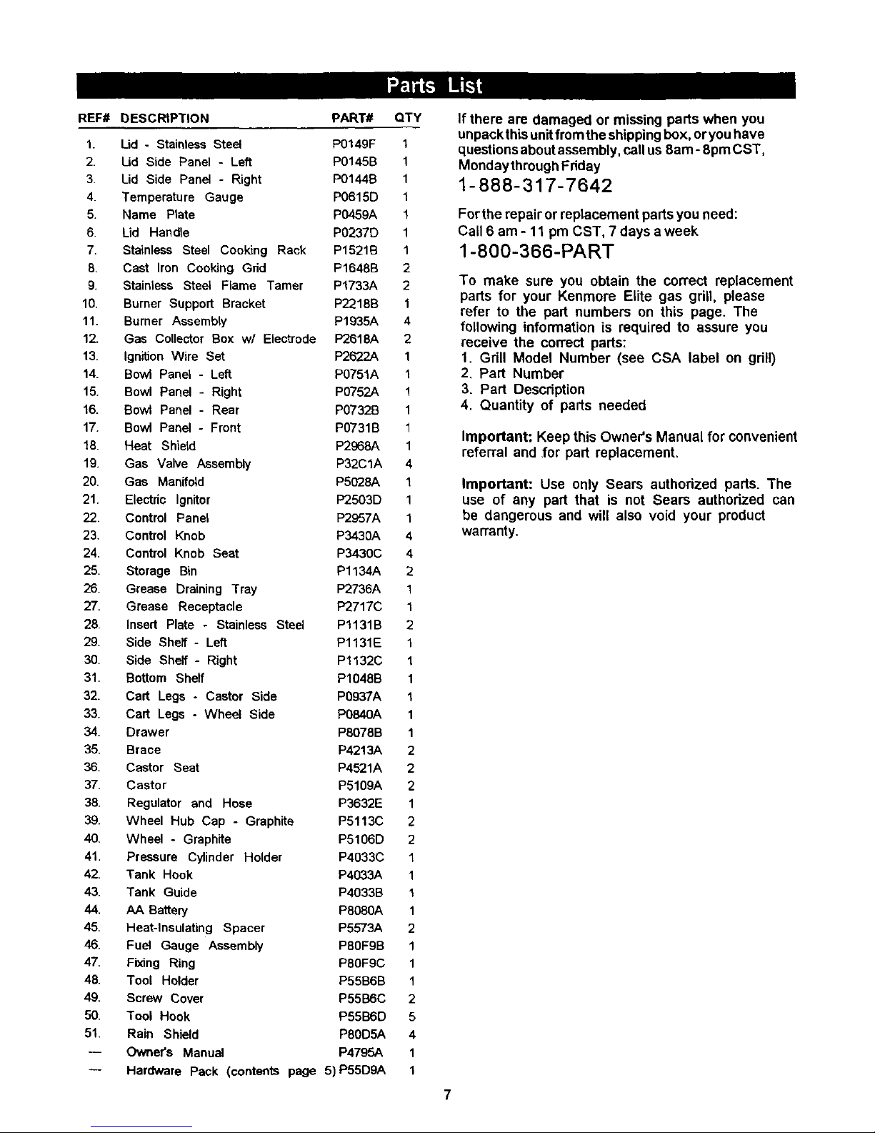
REF# DESCRIPTION PART# QTY
1. Lid - Stainless Steel P0149F 1
2. Lid Side Panel - Left P0145B 1
3. Lid Side Panel - Right P0144B 1
4. Temperature Gauge P0615D 1
5. Name Plate P0459A 1
6. Ud Handle P0237D 1
7. Stainless Steel Cooking Rack P1521B 1
8. Cast Iron Cooking Grid P1648B 2
9. Stainless Steel Flame Tamer P1733A 2
10. Burner Support Bracket P2218B 1
11. Burner Assembly P1935A 4
12. Gas Collector Box w/ Electrode P2618A 2
13. Ignition Wire Set P2622A 1
14. Bowl Panel - Left PO751A 1
15. Bowl Panel - Right P0752A 1
16. Bowl Panel - Rear PO732B 1
17. Bowl Panel - Front PO731B 1
18. Heat Shield P2968A 1
19. Gas Valve Assembly P32ClA 4
20. Gas Manifold P5028A 1
21. Electric Ignitor P'2503D 1
22. Control Panel P2957A 1
23. Control Knob P343OA 4
24. Control Knob Seat P3430C 4
25. Storage Bin P1134A 2
26. Grease Draining Tray P2736A 1
27. Grease Receptacle P2717C 1
28. Insert Plate - Stainless Steel P1131B 2
29. Side Shelf- Left Pl131E 1
30. Side Shelf- Right Pl132C 1
31. Bottom Shelf P1048B 1
32. Cart Legs - Castor Side P0937A 1
33. Cart Legs - Wheel Side P0840A 1
34. Drawer P8078B 1
35. Brace P4213A 2
36. Castor Seat P4521A 2
37. Castor P5109A 2
38. Regulator and Hose P3632E 1
39. Wheel Hub Cap - Graphite P5113C 2
40. Wheel - Graphite P5106D 2
41. Pressure Cylinder Holder P4033C 1
42. Tank Hook P4033A 1
43. Tank Guide P4033B !
44. AA Battery P808OA 1
45. Heat-Insulating Spacer P5573A 2
46. Fuel Gauge Assembly P80FgB 1
47. Fixing Ring P80F9C 1
48. Tool Holder P55B6B 1
49. Screw Cover P55B6C 2
50. Tool Hook P55B6D 5
51. Rain Shield P80D5A 4
-- Owner's Manual P4795A 1
-- Hardware Pack (contents page 5)P55D9A 1
If there are damaged or missing parts when you
unpackthis unit fmmthe shipping box, oryou have
questions about assembly, call us 8am- 8pm CST,
Mondaythmugh Fdday
1-888-317-7642
For the repair or replacement parts you need:
Call 6 am - 11 pm CST, 7 days a week
1-800-366-PART
To make sure you obtain the correct replacement
parts for your Kenmore Elite gas grill, please
refer to the part numbers on this page. The
following information is required to assure you
receive the correct parts:
1. Grill Model Number (see CSA label on gdll)
2. Part Number
3. Part Description
4. Quantity of parts needed
Important: Keep this Owner's Manual for convenient
referral and .for part replacement.
Important: Use only Sears authorized parts. The
use of any part that is not Sears authorized can
be dangerous and will also void your product
warranty.
7
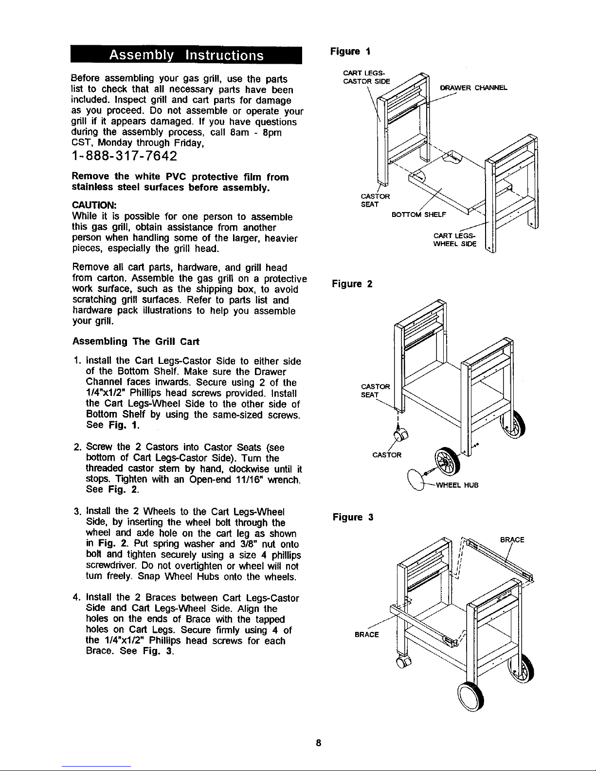
Before assembling your gas gdll, use the parts
list to check that all necessary parts have been
included. Inspect gnll and cart parts for damage
as you proceed. Do not assemble or operate your
grill if it appears damaged. If you have questions
during the assembly process, call 8am - 8pro
CST, Monday through Friday,
1-888-317-7642
Remove the white PVC protective film from
stainless steel surfaces before assembly.
CAUTION:
While it is possible for one person to assemble
this gas gdll, obtain assistance from another
person when handling some of the larger, heavier
pieces, especially the grill head.
Remove all cart pads, hardware, and gdll head
from carton. Assemble the gas grill on a protective
work surface, such as the shipping box, to avoid
scratching grilt surfaces. Refer to parts list and
hardware pack illustrations to help you assemble
your grill.
Assembling The Grill Cart
1. Install the Cart Legs-Castor Side to either side
of the Bottom Shelf. Make sure the Drawer
Channel faces inwards. Secure using 2 of the
114"x112" Phillips head screws provided. Install
the Cart Legs-Wheel Side to the other side of
Bottom Shelf by using the same-sized screws.
See Fig. 1.
2. Screw the 2 Castors into Castor Seats (see
bottom of Cart Legs-Castor Side). Tum the
threaded castor stem by hand, clockwise until it
stops. Tighten with an Open-end 11/16" wrench.
See Fig. 2.
3. Install the 2 Wheels to the Cart Legs-Wheel
Side, by inserting the wheel bolt through the
wheel and axle hole on the cart leg as shown
in Fig. 2. Put spring washer and 3/8" nut onto
bolt and tighten securely using a size 4 phillips
screwdriver. Do not overtighten or wheel will not
turn freely. Snap Wheel Hubs onto the wheels.
4. Install the 2 Braces between Cart Legs-Castor
Side and Cart Legs-Wheel Side. Align the
holes on the ends of Brace with the tapped
holes on Cart Legs. Secure firmly using 4 of
the 1/4"xl/2" Phillips head screws for each
Brace. See Fig. 3.
Figure 1
CART LEGS-
CASTOR SIDE
ORAWER CHANNEL
CASTOR
SEAT
BOTTOM SHELF
CART LEGS-
WHEEL SIDE
Figure 2
CASTOR
SEAT
I
CASTOR
HUB
Figure 3
BRACE
BRACE
8

AssemblingTheTankGuideand Grill Drawer
,
Attach the Pressure Cylinder Holder and Tank
Guide to the Cart Legs-Wheel Side as shown
in Fig. 4a. Align the holes of both parts with
the tapped holes on Cart Legs-Wheel Side.
Secure firmly using 4 of the 1/4"x112" Phillips
head screws provided.
2. Install a 1/4"x1/2" Phillips head screw to the
rear of each Drawer Track. Without these
screws the drawer will not stop propedy.
3. Slide the Drawer into the Drawer Tracks until
it stops. See Fig. 4b.
4,
Install a 1/4"x112" Phillips head screw to the
front of each Drawer Track. This important
step prevents the drawer from being pulled
outside the tracks. See Fig. 4b.
installing The Grill Head
.
Now that you've assembled the grill cart you
can install the pre-assembled Gdll Head.
See Fig. 5. To reduce the weight of the Gdll
Head, we suggest you open the Gdll Lid and
remove the packed components. Even with
the components removed, this step requires 2
people to lift and position the Gdll Head onto
the griU cart. Be sure to align the 2 holes
beneath the hang ledge on each side of the
Gdll Head with the 2 holes on each cross
brace of cart. Raise Gdll Lid and insert 4 of
the 1/4"xl-3/8" Phillips head screws and lock
nuts and tighten securely.
2. From the back side of grill head, install the
Grease Draining Tray. See Fig. 5.
3. Center the Grease Receptacle under Grease
Draining Tray. See Fig. 5.
Figure 4a
DRAWER TRACK
DRAWER
PRESSURE
CYLINDER
HOLDER
TANK GUIDE
Figure 4b
J
DRAWER
Figure 5
CROSS BRACE
GREASE RECEPTACLE
GRILL HEAD
i
/
//
GREASE
DRAINING TRAY
HANG LEDGE
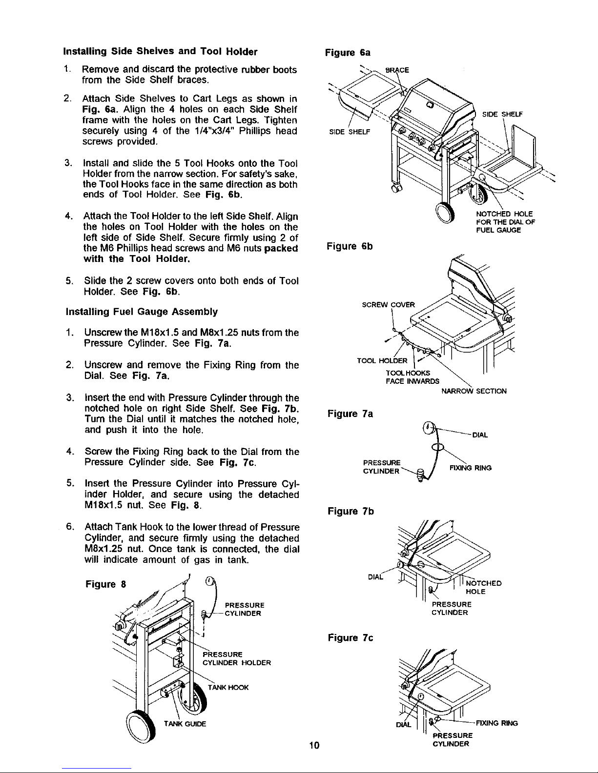
Installing Side Shelves and Tool Holder
1. Remove and discard the protective rubber boots
from the Side Shelf braces,
Figure 6a
2,
Attach Side Shelves to Cart Legs as shown in
Fig. 6a. Align the 4 holes on each Side Shelf
frame with the holes on the Cart Legs. Tighten
securely using 4 of the 1/4"x3/4" Phillips head
screws provided.
SIDE SHELF
SIDE SHELF
3.
Install and slide the 5 Tool Hooks onto the Tool
Holder from the narrow section. For safety's sake,
the Tool Hooks face in the same direction as both
ends of Tool Holder. See Fig. 6b.
4.
Attach the Tool Holder to the left Side Shelf. Align
the holes on Tool Holder with the holes on the
left side of Side Shelf. Secure firmly using 2 of
the M6 Phillips head screws and M6 nuts packed
with the Tool Holder.
5. Slide the 2 screw covers onto both ends of Tool
Holder. See Fig. 6b.
Installing Fuel Gauge Assembly
1. Unscrew the M18x1.5 and M8x1.25 nuts from the
Pressure Cylinder. See Fig. 7a.
2. Unscrew and remove the Fixing Ring from the
Dial. See Fig. 7a.
.
Insert the end with Pressure Cylinder through the
notched hole on right Side Shelf. See Fig. 7b.
Turn the Dial until it matches the notched hole,
and push it into the hole.
NOTCHED HOLE
FOR THE DIAL OF
FUEL GAUGE
Figure 6b
TOOL HOLDER
NARROW SECTION
Figure 7a
4.
5.
6.
Screw the Fixing Ring back to the Dial from the
Pressure Cylinder side. See Fig. 7c,
Insert the Pressure Cylinder into Pressure Cyl-
inder Holder, and secure using the detached
M18xl.5 nut. See Fig. 8.
Attach Tank Hook to the lower thread of Pressure
Cylinder, and secure firmly using the detached
M8x1.25 nut. Once tank is connected, the dial
will indicate amount of gas in tank.
Figure 8
CYLINDER
• ._J
_ANK HCOK
TANK GUIDE
PRESSURE
Figure 7b
DIAL
Figure 7c
FIXING RING
HOLE
PRESSURE
CYLINDER
DiAL
PRESSURE
10 CYLINDER
FIXING RING
 Loading...