

Page 1

Use & Care Guide
Model: 90109
Kenmore®
Liquid Propane
Gas Grill
P/N 19000343A0 (1110)
Sears Canada Inc.
Toronto, ON., M5B 2C3
www.sears.ca
™
Page 2
Table of Contents
Precautions
Warranty------------------------------------------------2
Safety Precautions--------------------------------2~4
Package Content List-----------------------------5~6
Hardware Contents----------------------------------7
Preparation--------------------------------------------7
Parts Diagram ---------------------------------------8
Parts List-----------------------------------------------9
Assembly Instructio ns---------------------------10-15
Lighting Instructions----------------------------16~17
Cleaning and Maintenance------------------------18
Troubleshooting--------------------------------------19
Cooking Instru ction----------------------------------20
Cooking Chart-----------------------------------------21
Kenmore Grill Warranty
One-Year Full Warranty on Kenmore Grill
If this grill fails due to a defecting material or
workmanship within one year from the date of
purchase, call 1-800-913-8999 (English) or 1-800648-5864 (French) to arrange for free repair (or
replacement if repair proves impossible).
Five-Year Limited Warranty on Stainless Steel
Burners
!
WARNING
Failure to comply with these instructions could
result in a fire or explosion that could cau se
serious bodily injury, death, or property damage.
WARNING
!
Your grill will get very hot. Never lean over the
cooking area while using your grill. Do not touch
cooking surfaces, grill housing, lid or any other
grill parts while the grill is in operation, or until
the gas grill has cooled down after use.
Failure to comply with these instructions may
result in serious bodily injury.
WARNING
!
1. Do not store or use gasoline or
other flammable liquids or
vapors in the vicinity of this or
any other appliance.
2. An LP cylinder not connected for
use shall not be stored in the
vicinity of this or any other
appliance.
For five years from the date of purchase, any
stainless steel burner that rusts through will be
replaced free of charge. After the first year from the
date of purchase, you pay for labor if you wish to
have it installed.
All warranty coverage excludes ignitor batteries and
grill part paint loss, discoloration or rusting, which are
either expendable parts that can wear out from
normal use within the warranty period, or are
conditions that can be the result or normal use,
accident or improper maintenance.
All warranty coverage is void if this grill is ever used
for commercial or rental purposes.
All warranty coverage applies only if this grill is used
in the Canada.
.
Sears Canada Inc.
Toronto, ON., M5B 2C3
!
DANGER
If you smell gas:
1. Shut off gas to the appliance.
2. Extinguish any open flame.
3. Open lid.
4. If odor continues, keep away
from the appliance and
immediately call your gas
supplier or your fire department.
Grill Installation Codes
The installation must conform with local codes or,
in the absence of local codes, with either the
national fuel gas code, ANSI Z 223.1/NFPA S4,
Natural gas and propane installation code, CSA
B149.1, or propane storage and handling code,
B149.2, or the standard for Recreational vehicles,
ANSI A 119.2, and CSA Z240 RV series
recreational vehicle code, as applicable.
LP gas grill models are designed for use with a
standard 20 lb. Liquid Propane Gas tank, not
included with grill. Never connect your gas grill to
an LP gas tank that exceeds this capacity.
2
Page 3

Precautions
A tank of approximately 12 inches in diameter by 18-1/2
inches high is the maximum size LP gas tank to use.
You must use an OPD gas tank which offers an
Overfill Prevention Device.
This safety feature prevents the tank from being
overfilled which can cause malfunction of the LP gas
tank, pressure regulator and/or grill.
The LP gas tank must be constructed and marked in
accordance with specifications of the U.S. Dept. of
Transportation (DOT). In Canada, the LP gas tank must
meet the National Standard of Canada ,CAN/CSA-B339 ,
Cylinders , spheres and Tubes for Transportation of
Dangerous Goods and Commission .
1. The LP gas tank must have a shutoff valve,
terminating in an LP gas supply tank valve outlet, that is
compatible with a Type 1 tank connection device. The LP
gas tank must also have a safety relief device that has a
direct connection with the vapor space of the tank.
2. The tank supply system must be arranged for vapor
withdraw.
3. The LP gas tank used must have a collar to protect the
tank valve.
Proper Placement and Clearance of Grill
Never use your gas grill in a garage, porch, shed,
breezeway or any other enclosed area. Your gas grill is
to be used outdoors only, at least 24 inches from the
back and side of any combustible surface. Your gas grill
should not be used under overhead combustible
construction . Do not obstruct the flow of ventilation air
around the gas grill housing.
• Do not install this outdoor gas grill in or on recreational
vehicles or boats
• Keep outdoor gas grill area clear and free from
combustible materials, gasoline and other flammable
vapors and liquids
• Do not obstruct the flow of combustion and ventilation
air. Check for this each time prior to using grill.
• Never connect an unregulated LP gas tank to your gas
grill. The gas pressure regulator assembly supplied with
your gas grill is adjusted to have an outlet pressure of 11”
water column (W.C.) for connection to an LP gas tank.
• Only use the pressure regulator and the hose assembly
supplied with your gas grill. Replacement pressure
regulators and hose assemblies must be those specified
in this manual.
• Have your LP gas tank filled by a reputable
propane gas dealer and visually inspected and requalified at each filling.
• Do not store a spare LP gas tank under or
• near this appliance.
• Never fill the tank beyond 80 percent full . If this
information is not followed exactly a fire causing
death or serious injury may occur.
• Always keep LP gas tanks in an upright position.
• Do not store or use gasoline or other flammable
vapors and liquids in the vicinity of this gas grill.
• Do not subject the LP gas tank to excessive heat.
• Never store an LP gas tank indoors. If you store
your gas grill in the garage or other indoor
location, always disconnect the LP gas tank first
and store it safely outside.
Always keep the LP cylinder at
90° (upright) orientation to
provide vapor withdraw.
• Place dust cap on cylinder valve outlet whenever
the cylinder is not in use. Only install the type of
dust cap on the cylinder valve outlet that is
provided with the cylinder valve. Other types of
caps or plugs may result in leakage of propane.
• LP gas tanks must be stored outdoors in a wellventilated area and out of reach of children.
Disconnected LP gas tanks must not be stored in
a building, garage or any other enclosed area.
• When your gas grill is not in use the gas must be
turned off at the LP gas tank.
• The pressure regulator and hose assembly must
be inspected before each use of the grill. If there
is excessive abrasion or wear or if the hose is cut,
it must be replaced prior to the grill being used
again.
• Keep the gas pressure regulator hose away from
hot grill surfaces and dripping grease. Avoid
unnecessary twisting of hose. Visually inspect the
hose prior to each use for cuts, cracks, excessive
wear or other damage. If the hose appears
damaged do not use the gas grill. Call 1-800-9138999 (English) or 1-800-648-5864 (French) for a
replacement hose.
• Never light your gas grill with the lid closed or
before checking to ensure the burner tubes are
fully seated over the gas valve orifices.
• Never allow children to operate your grill.
3
Page 4

WARNING
!
A strong gas smell, or the hissing sound of gas
indicates a serious problem with your gas grill or
the LP gas tank. Failure to immediately follow the
steps listed below could result in a fire or
explosion that could cause serious bodily injury,
death, or property damage.
• Shut off gas supply to the gas grill.
• Turn the control knobs to OFF position.
• Put out any flame with a proper fire extinguisher.
• Open Grill Lid.
• Get away from the LP gas tank.
• Do not try to fix the problem yourself.
• If odor continues or you have a fire you can not
extinguish, call your fire department. Do not call
near the LP gas tank because your telephone is
a form of electrical device and could create a
spark resulting in fire and/or explosion.
NOTE: The normal flow of gas through the pressure
regulator and hose assembly can create a humming
noise. A low volume of noise is perfectly normal and
will not interfere with operation of the grill. If humming
noise is loud and excessive you may need to purge
air from the gas line or reset the pressure regulator
excess gas flow device. This purging procedure
should be done every time a new LP gas tank is
connected to your grill. For help with this procedure
refer to page 16, Item 4 of “If Grill Still Fails To Light”,
or call the Grill Information Center at 1-800-913-8999
(English) or 1-800-648-5864 (French).
Burner Flame Check
Visually check the burner flames prior to each use. The
flames should look like picture, if they do not, refer to the
cleaning burner tubes and ports, see page 18 of this
manual.
CAUTION: Beware of Flash-Back
CAUTION: Spiders and small insects occasionally
spin webs or make nests in the grill burner tubes
during transit and warehousing. These webs can lead
to gas flow obstruction which could result in a fire in
and around burner tubes. This type of fire is known as
“FLASH-BACK” and can cause serious damage to
your grill and create an unsafe operating condition for
the user.
Although an obstructed burner tube is not the only
cause of “FLASH-BACK”, it is the most common
cause.
To reduce the chance of “FLASH-BACK”, you must
clean the burner tubes before assembling your grill,
and at least once a month in late summer or early fall
when spiders are most active. Also perform this
burner tube cleaning procedure if your grill has not
been used for an extended period of time.
See Cleaning Burner Tubes and Ports on page # 18.
4
Page 5
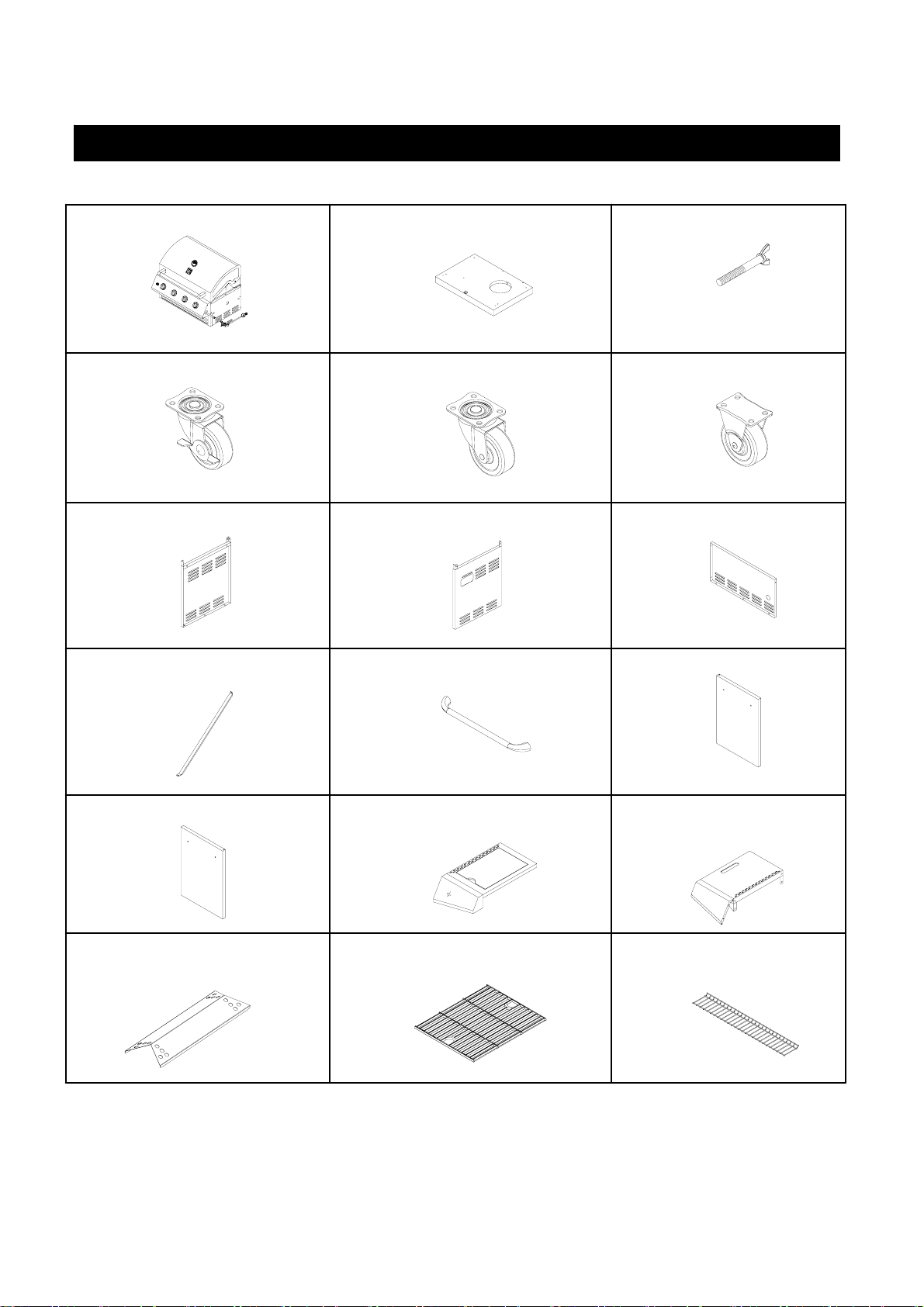
PACKAGE CONTENTS LIST
C. Tank Tray Bolt---1pc.B. Bottom panel----1pc.A. Firebox--------1pc.
3
0
2
0
0
0
4
0
0
1
1
0
0
50
5
0
0
5
5
0
0
2
5
C
F
0
3
0
6
5
0
0
70
0
F. Caster----------2pcs.E. Swivel Caster---------1pc.D. Swivel Caster with Brake---1pc.
I. Back panel----1pc.H. Side Panel, Right-----1 pc.G. Side Panel, Left-----1pc.
M. Door Right-----1pc.
N. Side Burner bowl assembly frame
with Side burner control panel-----1pc.
L. Door, Left------1 pc.K. Door handle-----2pcs.J. Gas Tank Barrier Bar---1pc.
O. Left side shelf with side
shelf front panel---------1pc.
S. Warming Racket-------1pcs.R. Cooking Grid---2pcs.P. Heat Diffuser--------4pcs.
5
Page 6
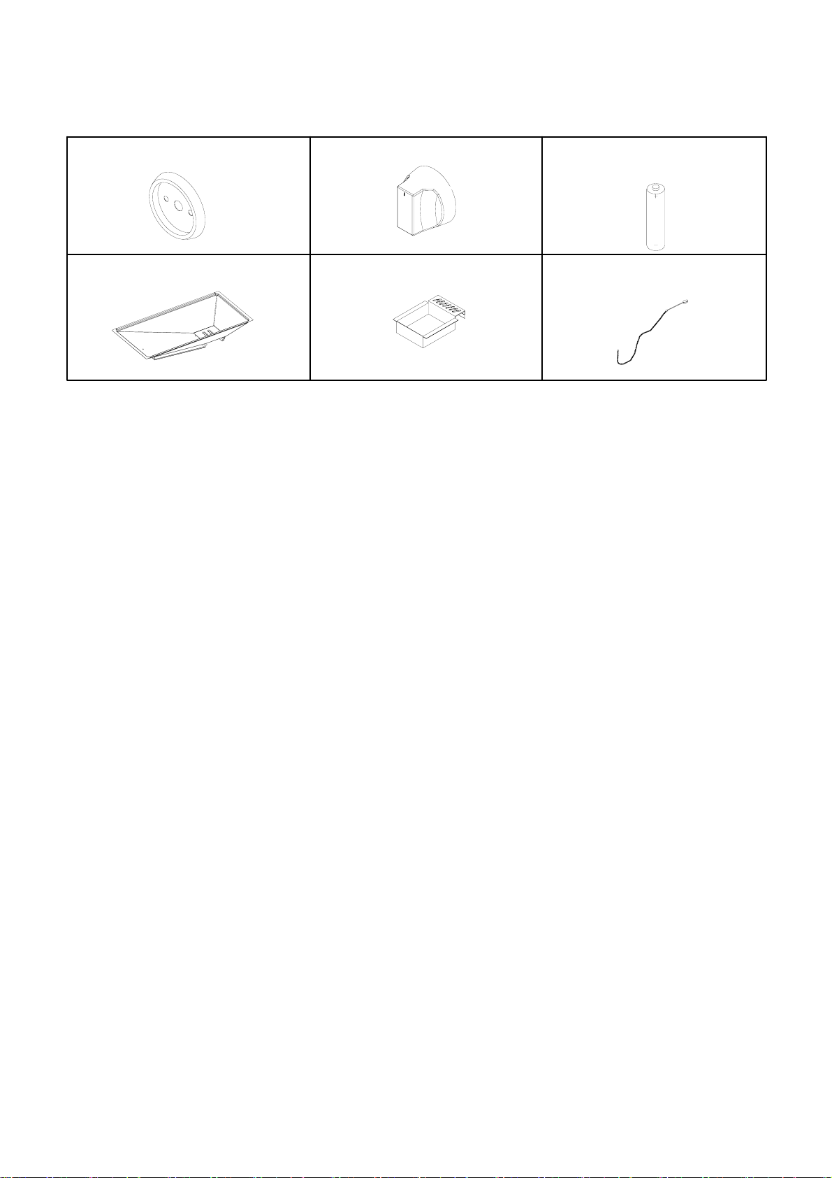
U.. Control Knob-------------1 pcT. B ezel---------------------------1 pc
V.1.5 Volt “AA” Size Alkaline
Battery----------1pc.
Y. Manual Lighting Stick-----1pc.X. Grease Cup----------------1pcW. Grease Tray -----1pc.
6
Page 7

Hardware Pack Contents
Item Description Specification Quantity
Phillips Head Screw
AA 1/4 x 15mm
16 pcs
Phillips Head Screw
BB
1/4 x 10mm 14 pcs
Phillips Head Screw
CC 5/32 x 8m m 15pcs
Flat Head Screw
DD 5/32 x 8mm
8 pcs
Flat Washer
4pcsEE 1/4
Lock Washer
FF
1/4 26pcs
Lock Washer
GG 11 pcs5/32
Hex Wrench
HH 5/64 1pc
Preparation
Before beginning assembly, make sure all parts are present. Compare parts with package contents list and
diagram above. If any part is missing or damaged, do not attempt to assemble the product. Contact
customer service for replaceme nt parts.
•Tools required for Assembly.
Phillips Screwdriver (not included) and Wrench (not included)·
Phillips Screwdriver Wrench
• Note: The left and right sides of the grill are on your left and right as you face the front of the grill.
7
Page 8
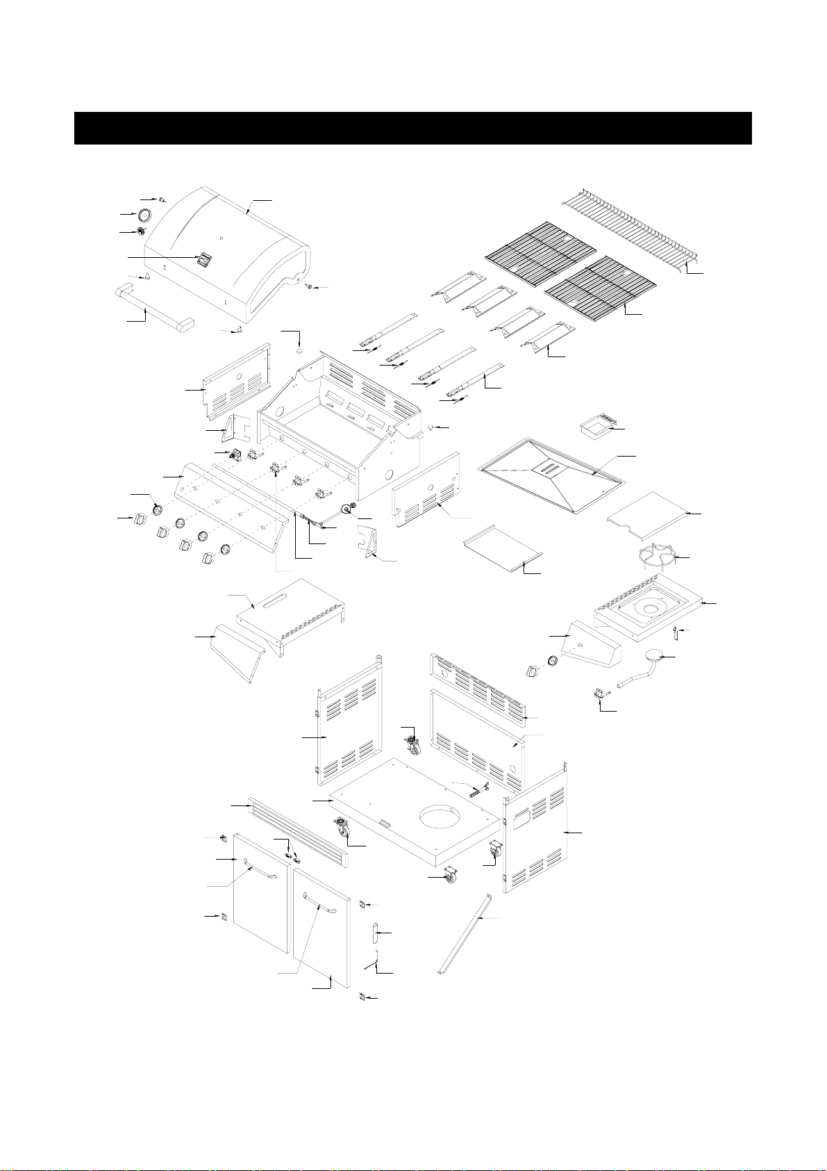
Model 90109 Parts diagram
0 3
0 4
0 5
0 6
0 7
1 8
0 2
1 7
1 6
0 8
1 0
1 1
0 6
1 9
0 6
0 1
5 8
1 5
0 2
5 3
1 3
1 4
5 2
12
5 1
3 7
5 0
0 6
0 9
5 7
5 6
5 5
5 4
4 9
4 8
4 6
4 5
4 7
4 4
2 0
3 0
3 3
3 0
3 1
2 8
2 9
3 3
2 1
2 5
3 2
2 4
3 0
3 0
2 3
3 5
3 4
2 7
2 6
2 7
3 6
4 1
3 9
4 3
4 2
4 0
3 8
2 2
8
Page 9
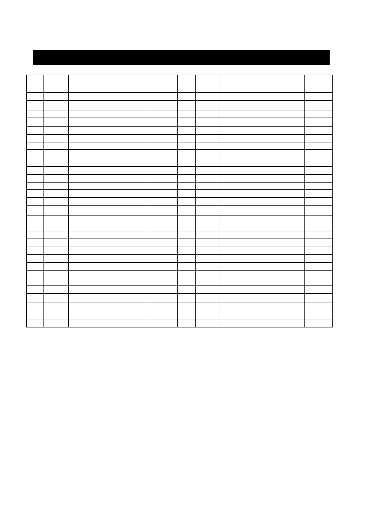
Model 90109 Parts List
DESCRIPTIONPARTSKEY#QUANTITYDESCRIPTIONPARTSKEY#
0773-033331Temperature Gauge0773-0044
Control Knob0773-01818
QUANTIT
Y
4Door Hinge0773-030301Main Lid0773-0011
1Front Door, Left0773-031312Main Lid Screw0773-0022
1Front Door, Right0773-032321Temperature Gauge Housing0773-0033
2Door Handle
1Lighting Rod0773-034341Logo0773-0055
1Lighting Rod Cover0773-035354Hood Buffer0773-0066
1Gas Tank Barrier Bar0773-036361Main Lid Handle0773-0077
1control panel support bracket, Right 0773-037371Flange, Left0773-0088
1Back Panel0773-038381Flange, Right0773-0099
1Back Panel, Top0773-039391control panel support bracket, left 0773-01010
1Side Burner Gas Valve0773-040401Pulse Igniter Module0773-01111
1Side Burner Front Panel0773-041411Regulator, LP0773-01212
1Side Burner Pipe Assembly0773-042421Side Manifold0773-01313
1Side Burner Igniter Wire0773-043431 Side Burner Flex Gas Line0773-01414
1Side Burner Bowl Assembly0773-044441Main Manifold0773-01515
1Side Burner Cooking Grate0773-045451Main Control Panel0773-01616
1Side Burner Lid0773-046465Bezel0773-01717
1Gas Tank Heat Shield0773-047475
1Grease Slide Panel0773-048481Side Shelf, Left0773-01919
1Grease Box0773-049491Side Shelf Front Panel, Left0773-02020
1Main Burner Igniter Wire A0773-050501Side Panel, Left0773-02121
1Main Burner Igniter Wire B0773-051511Side Panel, Right0773-02222
1Main Burner Igniter Wire C0773-052521Swivel Caster with Brake 0773-02323
1Main Burner Igniter Wire D0773-053531Swivel Caster0773-02424
4Main Burner0773-054541Bottom Panel, LP0773-02525
4Heat Diffuser0773-055551Tank Tra y B ol t0773-02626
2Cooking Grid with Hole0773-056562Caster0773-02727
1Warming Rack0773-057571Cart Frame, Front0773-02828
4Main Gas Valve0773-058582Door Magnet0773-02929
If you are missing hardware or have damaged
parts after unpacking grill, call 1-800-913-8999
(English) or 1-800-648-5864 (French) for
replacements.
To order replacement parts after using grill, call:
1-800-913-8999 (English) or 1-800-648-5864
(French).
To make sure you obtain the correct replacement
parts for your Kenmore gas grill, pl ease refer to
the part numbers on this page.
Important: Use only parts listed above. When ordering
parts, providing the following information:
1. Model #
2. Serial # (found inside the front panel of your grill)
3. Part Number (see PART# in chart)
4. Part Description
5. Quantity of parts needed
9
Page 10
Assembly Instructions
Fig. 1
CAUTION: While it is possible for one person to
assemble this grill, obtain assistance from another
person when handling some of the la rger, heavier
pieces.
Note: Be sure to slide grease tray out of back of grill
head and remove all packaging from tray.
1. Use the parts list to check that all parts have been
included.
2. Inspect the grill for damage as you assemble it. Do not
assemble or operate the grill if it appears damaged. If there
are damaged or missing parts when you unpack the
shipping box, or you have questions during the assembly
process, call:
For Assembly Questions, call 1-800-913-8999 (English)
or 1-800-648-5864 (French)
8AM – 5 PM PST, Monday through Friday.
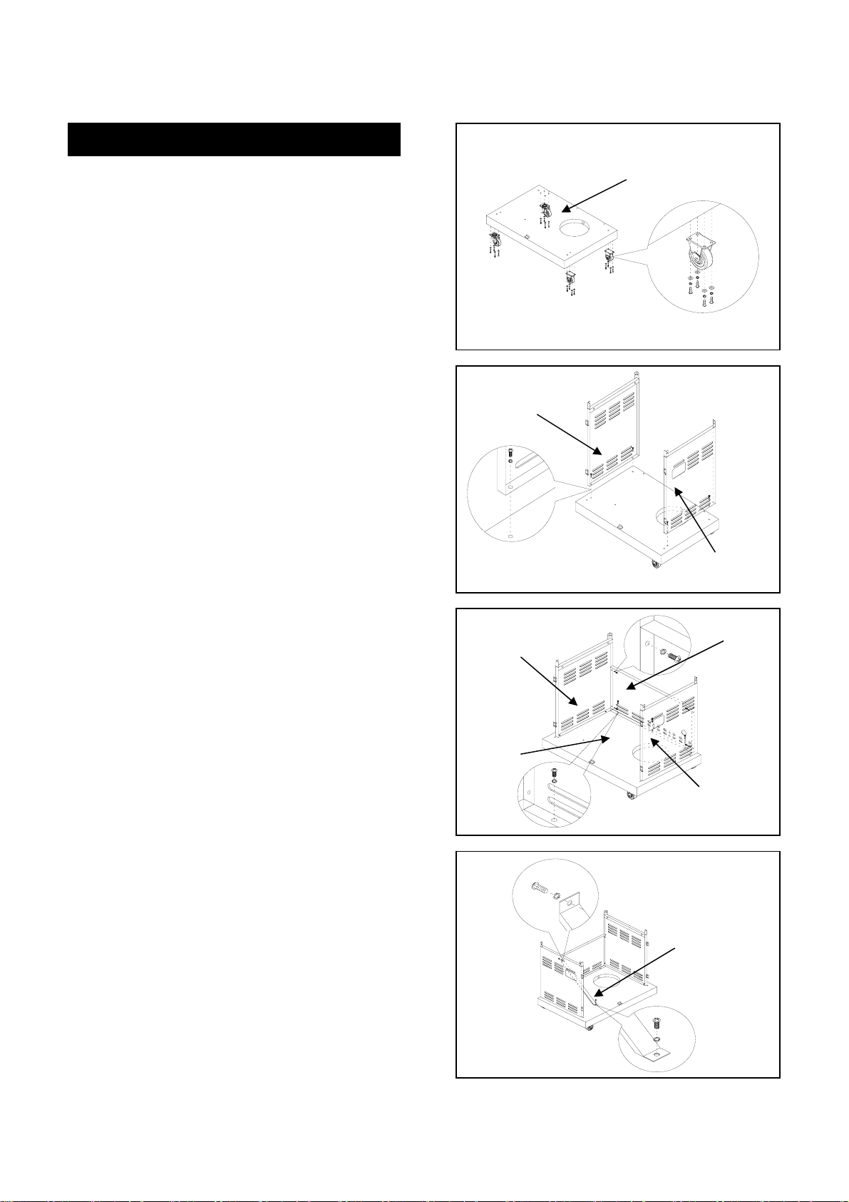
1. Assembling Grill Cart
(a) Attach four casters to bottom panel (B) using (16) 1/4
x15mm Phillips head screws (AA), (16) 1/4 lock washers
(FF). Note: (D) is swivel caster with brake, (E) is swivel
caster, (F) are straight casters. (Fig.1)
Hint: For ease of caster assembly, turn bottom panel
upside down.
E
Fig. 2
Fig. 3
D
F
G
G
B
F
H
I
(b) Attach left & right side panels (G & H) to bottom panel
(B) using (4) 5/32 x 8mm Phillips head screws (CC) with (4)
5/32 lock washers (GG). (Fig.2)
(c) Attach back panel (I) to bottom panel (B) using (3) 5/32
x 8mm Phillips head screws (CC) with (3) 5/32 washers
(GG). Attach back panel (I) to side panel (G&H) using (4)
1/4 x 10mm Phillips head screws (BB) with (4)1/4 lock
washers (FF) . (Fig.3)
(d) Attach gas tank barrier bar (J) to back panel (I) using (1)
5/32 x 8mm Phillips head screw (CC) and (1) 5/32 lock
washer (GG) from the back panel side. Attach bar to bottom
panel using same size screw and lock washer. (Fig. 4)
B
H
Fig. 4
J
10
Page 11
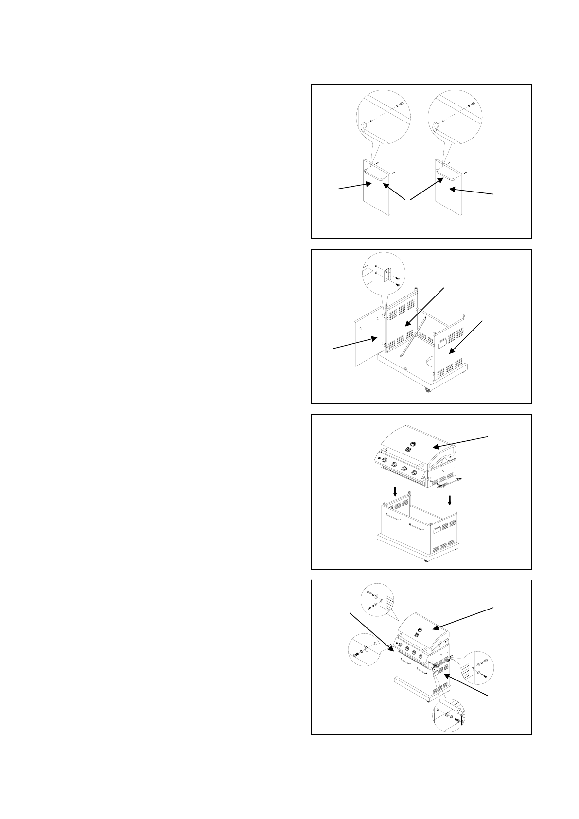
(e) Attach door handle (K) to left door (L) using (2) 5/32 x
8mm Phillips head screws (CC) and (2) 5/32 lock washers
(GG). Repeat to assemble the other door handle to right
door (M). (Fig.5)
(f) Attach two doors (L & M) to side panels (G & H) using
(8) 5/32 x 8mm flat head screws (DD). (Fig. 6)
Fig. 5
2. Firebox Assembly
(a) Be sure grill cart doors are closed to stabilize cart.
Remove grill head (A) from carton. Place onto cart from
above as shown in (Fig. 7)
CAUTION: Grill head is heavy . To avoid injury, obtain
the help of an assistant for this step. Also, make sure
doors remain closed when placing grill head onto
cart. DO NOT open doors until grill head is securely
mounted to cart.
(b) Attach grill head (A) to left and right side panels (G &
H) using (6) 1/4 x 10mm Phillips head screws (BB) and (6)
lock washers (FF). (Fig. 8)
L
Fig. 6
L
Fig. 7
M
K
G
H
3
0
0
0
2
0
4
0
0
1
1
0
5
0
0
5
5
5
0
0
0
0
2
5
F
0
C
6
3
0
0
5
0
7
0
0
A
11
Fig. 8
G
0
3
2
0
0
0
4
0
0
1
1
0
0
5
0
5
0
5
5
0
0
0
2
5
C
F
0
0
3
6
0
5
0
7
0
0
A
H
Page 12
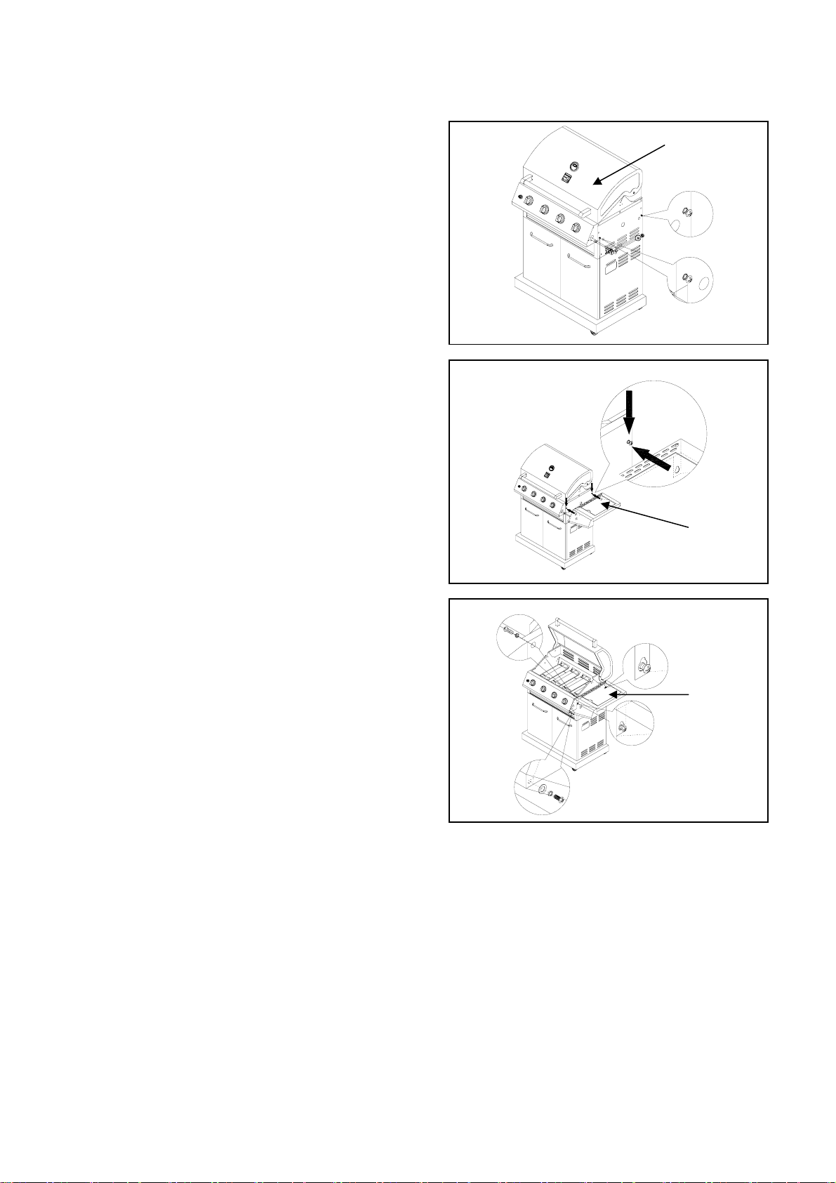
3. Side Burner & Side Shelf Assembly
(a) Loosen (2) preinstalled 1/4 x 10mm Phillips head
screws and (2) ¼ lock washers from right side of grill
head (A) as shown. Do not screw out fully; leave ¼
extended for shelf assembly. (Fig. 9)
(b) Through side burner shelf keyholes, hang side
burner shelf (N) on two loosened screws. (Fig. 10)
(c) Using (2) 1/4 x 10mm Phillips head screws (BB) and
(2) 1/4 flat washers (EE), attach side burner shelf (N) to
grill head from inside the firebox. Insert (1) 5/32 x 8
mm Phillips head screws (CC) and (1) 5/32 lock
washers (GG) to attach the side burner shelf front panel
to the control panel (Fig 11).Fully tighten the two
loosened screws to secure shelf to firebox.
(d) Repeat steps (a) through (c) to install side shelf.
Fig.9
Fig.10
A
3
0
0
2
0
0
4
0
0
1
1
5
0
0
0
5
0
5
5
0
0
0
2
5
C
F
0
6
3
0
5
0
0
7
0
0
0
3
0
2
0
0
4
0
0
1
1
0
0
5
0
5
0
5
0
5
0
0
2
5
0
F
C
6
5
3
0
0
0
7
00
N
Fig.11
N
12
Page 13
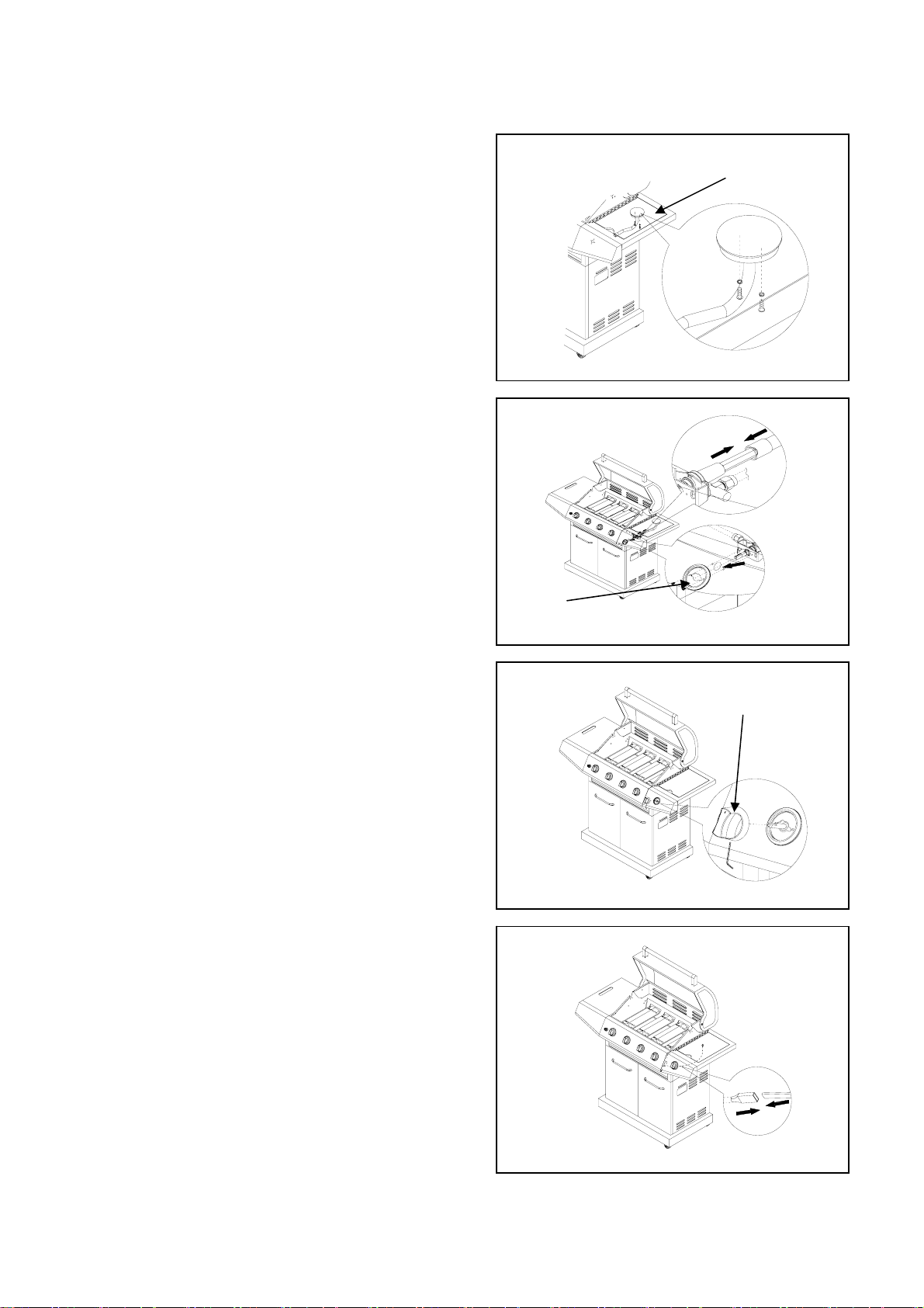
4. Side Burner Valve Assembly
(a) Remove side burner grate from side burner shelf and
set aside. Remove the two Phillips head screws
attaching side burner (N) to shelf to make room to install
side burner valve. See (Fig.12)
(b) Remove two screws from side burner control valve
face. Insert side burner valve control stem through hole
in side burner control panel . Place side burner control
knob bezel (T) over side burner valve control stem.
Secure bezel to control panel and valve with 2 screws
removed above. (Fig . 13A1).
Fig. 12
N
(c) Insert side burner tube over side burner valve orifice
(Fig. 13B1). Use the two previously removed side burner
screws to reattach side burner to side burner shelf.
(d) Push control knob (U) onto valve control stem, and
tighten use hex wrench. (Fig.14)
(e) Plug ignition wire into igniter wire hanging from
electrode on underside of burner (Fig.15).
(f) Replace the side burner grate into the side burner
shelf.
Fig. 13
Fig. 14
B1
T
A1
U
13
Fig. 15
Page 14
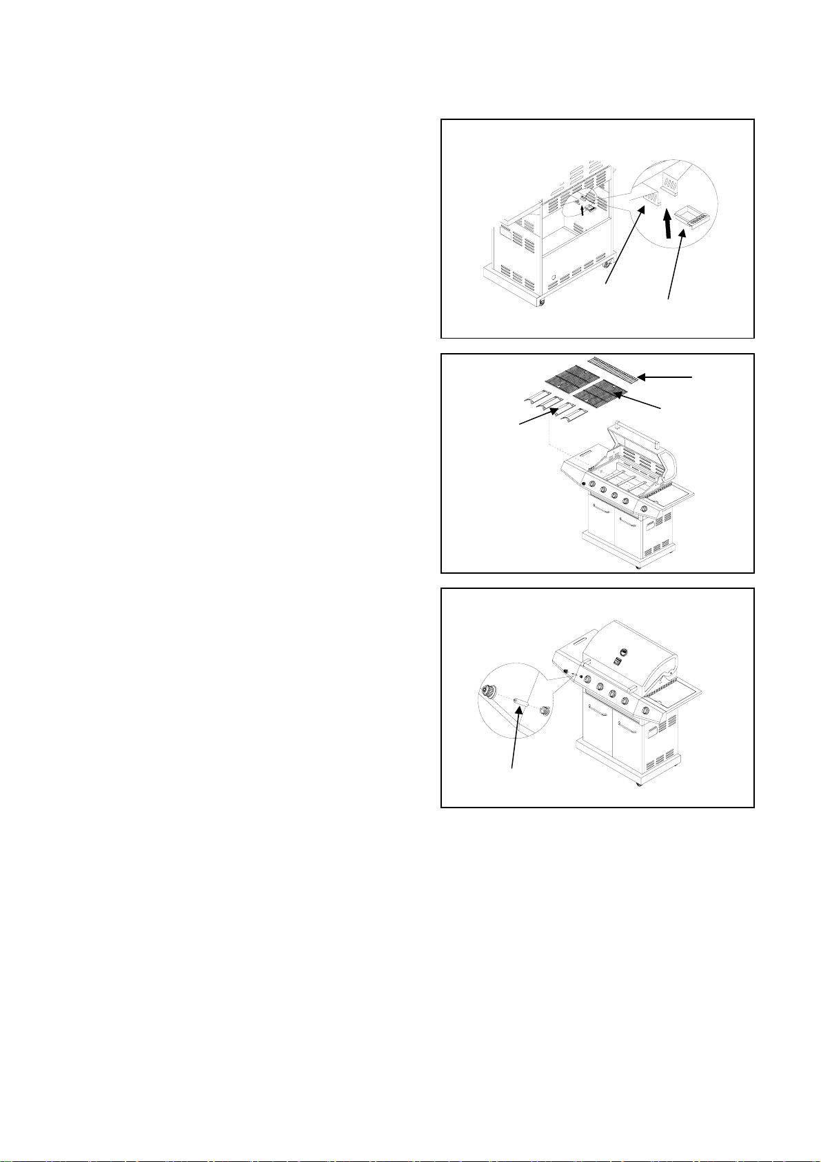
5. Grease Cup Assembly
From the back, pull out grease tray (W), remove a ny
packaging materials from it, then insert grease cup (X) into
grease tray (W) as shown in (Fig.16). Push grease tray
back into grill.
6. Installing Cooking Components
(a) Place heat diffusers over burners as shown. Diffuser
ends insert into channels on front and back of firebox.
(Fig. 17)
(b) Evenly space cooking grates (R) on the ledge above
heat diffusers. (Fig.17)
To obtain sear marks in cooked meat, be sure to insert
grates so that side with four corner feet faces down.
(c) Insert legs of warming rack (S) into the holes in the top
of firebox side panels. (Fig.17)
7. Battery Assembly
(a) Unscrew the ignition battery cap. (Found at far left of
control panel)
Fig.16
w
X
Fig.17
S
R
P
(b) Install battery (V) into ignition box with positive terminal
facing outward.
(c) Replace the ignition battery cap after the battery has
been installed. (Fig. 18)
Fig.18
3
0
0
2
0
0
4
0
0
1
1
5
0
0
0
5
5
0
5
0
0
0
2
5
0
F
C
6
0
3
0
5
0
7
0
0
V
14
Page 15
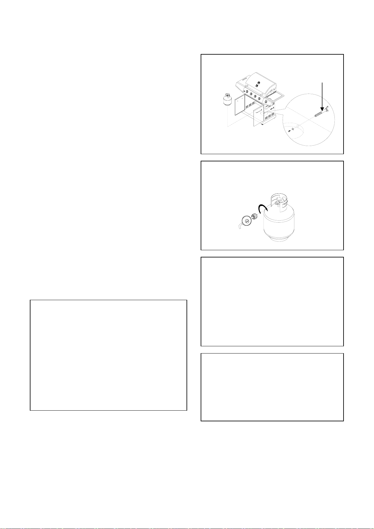
8. Connecting LP Gas Tank to LP Grill
(a) From front of the cart, place foot ring of 20 lb tank into
the hole in bottom panel. Make sure the tank valve is in
OFF position. Use the tank bolt to secure the tank in a
fixed position (Fig.19).
(b) Check the tank valve to ensure it has proper external
mating threads to fit the hose and pressure regulator
assembly provided.
(c) Make sure all burner valves are in OFF po siti on.
(d) Inspect the valve connection port and pressure regulator
assembly. Look for damage or debris. Remove any debris.
Inspect hose for damage. Never use damaged or plugged
equipment.
(e) When connecting pressure regulator and hose
assembly to tank valve, hand tighten quick coupling nut
clockwise to a full stop. (Fig.20) Do not use a wrench to
tighten because it could damage the quick coupling nut and
result in a hazardous condition.
(f) Slowly open tank valve fully (counterclockwise). Use a
soapy water solution to check all connections for leaks
before attempting to light your grill (see next page for gas
leak check instructions). If a leak is found, turn tank valve
off and do not use your grill until the leak is repaired.
CAUTION: When the appliance is not in use, gas must
be turned off at the supply tank.
DISCONNECTING THE LIQUID PROPANE
CYLINDER
Turn the grill burner valves “OFF” and make sure the
grill is cool.
Turn the Liquid Propane Cylinder valve “OFF” by
turning clockwise until it stops.
Detach the pressure regulator assembly from the
cylinder valve by turning the quick coupling nut
counterclockwise.
Place dust cap on cylinder valve outlet whenever the
cylinder is not in use. Only install the type of dust cap
on the cylinder valve outlet that is provided with the
cylinder valve. Other types of caps or plugs may
result in leakage of propane.
Fig.19
C
3
0
0
2
0
0
4
0
0
1
1
5
00
0
5
0
5
5
0
0
0
2
5
0
F
C
6
00
3
5
0
7
0
0
Fig.20
pressure regulator
Connection
Congratulations
Your Kenmore gas grill is now ready for use.
Before the first use and at the beginning of each
season (and whenever the LP gas tank has
been changed):
1. Read all safety, lighting and operating
instructions.
2. Check gas valve orifices, burner tubes and
burner ports for any obstructions.
3. Perform gas leak check according to
instructions found on next page of the manual.
Important
Before cooking on your grill the first time, wash
cooking grids and cooking rack with warm ,
soapy water. Rinse and dry thoroughly. Season
with cooking oil regularly. After cooking is
completed, turn grill to HIGH setting for 3 to 5
minutes to burn off excess grease or food
residue.
15
Page 16
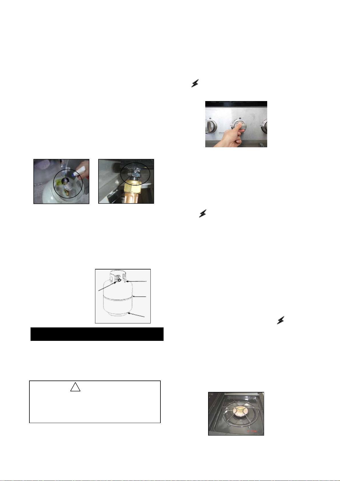
Checking for LP gas leaks
Never test for leaks with a flame. Prior to first use, at
the beginning of each season, or every time your LP
gas tank is changed, you must check for gas leaks.
1. Make a 50/50 (soap/water) mild soap solution.
2. Turn the control knobs to full OFF position; then turn
gas ON at supply tank.
3. Apply the soap solution with a clean brush to all gas
connections. See below. If growing bubbles appear
in the solution the connections are not properly
sealed. Check each fitting and tighten or repair as
necessary.
3. Be sure all gas connections are securely
tightened.
4. Turn on gas supply.
5. Open the grill main lid.
6. Push and turn any main burner control knob to
HI position. Push Electronic Ignition button for
3 to 5 seconds to light burner.
Gas Connection Leak Check
4. If you have a gas connection leak you cannot repair,
turn gas OFF at supply tank, disconnect fuel line
from your grill and call 1-800-913-8999 (English) or
1-800-648-5864 (French) or your gas supplier for
repair assistance.
5. Also apply soapy solution to the tank seams. See
below. If growing bubbles appear, shut tank OFF
and do not use or move it! Contact an LP gas
supplier or your fire department for assistance.
Gas Tank Leak Check
Grill Lighting Instruction
Grill Lighting Instructions for Main Burners
1. Do not smoke while lighting grill or checking gas
supply connections.
2. Be sure that LP gas tank is sufficiently full.
WARNING
!
Failure to open grill lid during the lighting
procedure could result in a fire or explosion
that could cause serious bodily injury, death,
or property damage.
7. If the burner does not light after 5 seconds, turn
knob to OFF. Turn gas OFF at LP tank and wait
5 minutes for gas to clear. Then turn gas ON at
tank and repeat step 5
8. If burner still does not light, see Match Lighting
section and If Grill Still Fails to Light section on
following page.
9. To light additional burners, turn burner knob(s)
to HI . Push and hold electronic ignition button
to light burner. Adjust knob(s) to desired setting.
USING THE SIDE BURNER:
Inspect the gas supply hose prior to turning the gas
“ON”. If there is evidence of cuts, wear or abrasion,
it must be replaced prior to use. Do not use the
side burner if the odor of gas is present.
WARNING: Always keep your face and body as
far away from the burner as possible when
lighting.
LIGHTING INSTRUCTIONS FOR SIDE BURNER
1. Open side burner lid fully.
2. Push and turn side burner knob to HI position.
Push and hold Electronic Ignition button for 3-5
seconds to light burner.
3. If the side burner does not light after 5 seconds,
turn knob to OFF. Turn gas OFF at LP tank and
wait 5 minutes for gas to clear. Then turn gas
ON at tank and repeat step 2.
4. If burner still does not light, see Match Lighti ng
section and If Grill Still Fails to Light Section on
following page.
16
Page 17
!
WARNING
Never lean over the grill cooking area while
lighting your gas grill. Keep your face and body
a safe distance (at least 18 inches) from the
cooking grid surface when lighting your grill by
match.
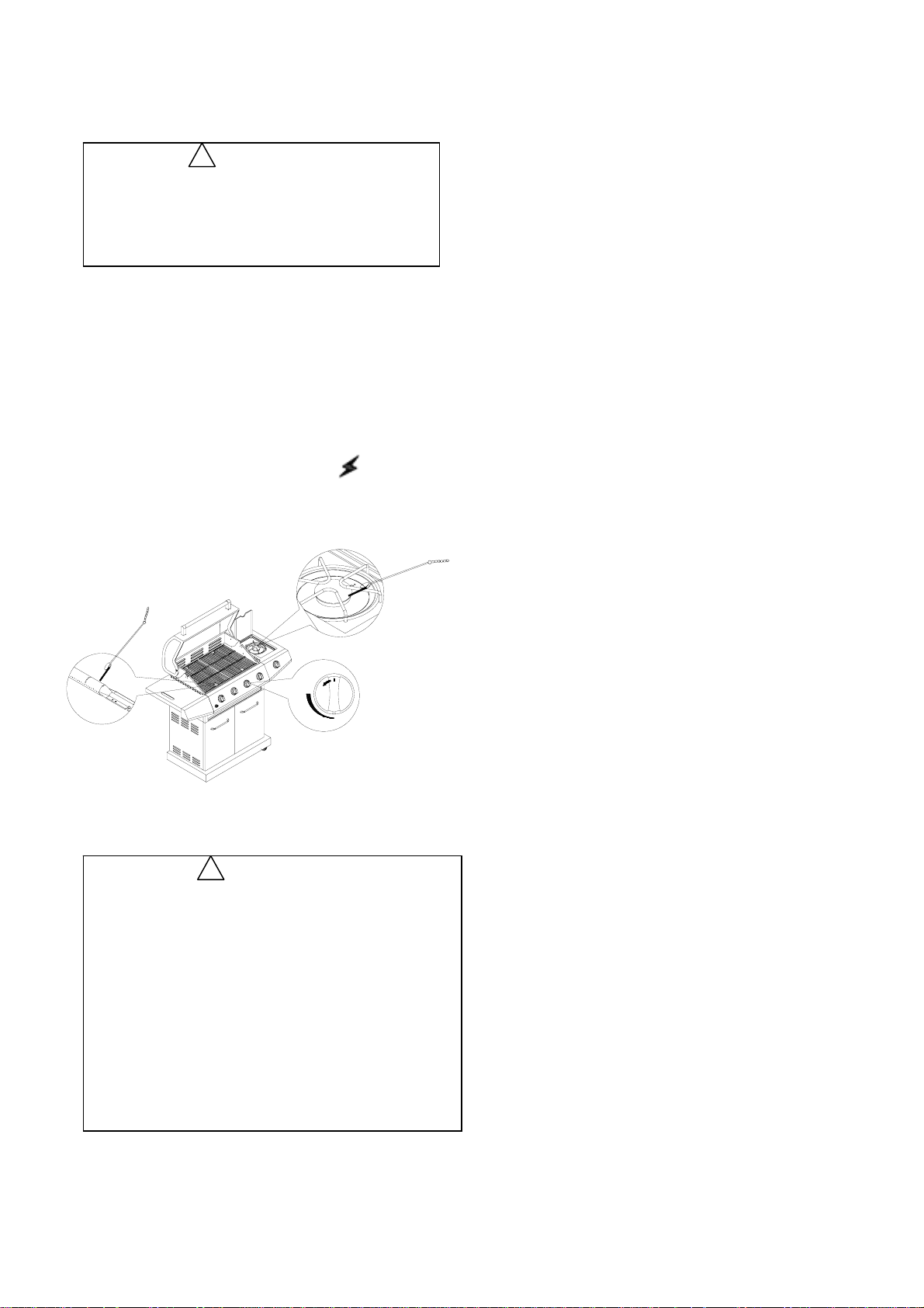
Manually Lighting Your Grill by Match
1. Insert a match into the manual lighting stick.
2. Follow steps 1 through 5 of the Basic Lighting
Procedure.
3. Light the match and extend the lighting stick to
cooking grid surface.
4. Turn the desired control knob to the HI
position setting to release gas. The burner should
light immediately.
If Grill Still Fails To Light
1. Check gas supply and connections for leaks. Check
that all wire connections are secure.
2. Repeat basic lighting procedure. If your grill still
fails to operate, turn the gas off at source, turn the
control knobs to OFF, then check the following:
• Misalignment of burner tubes over orifices
Correction: Reposition burner tubes over orifices.
• Plugged orifice
Correction: Remove burners from grill, carefully lift
each burner up and away from gas valve orifice.
Remove the orifice from gas valve and gently clear
any obstruction with a fine wire. Then reinstall all
orifices, burners, and cooking components.
3. If an obstruction is suspected in grill burner valves,
please call for repair service at 1-800-913-8999
(English) or 1-800-648-5864 (French) .
4. If the grill still does not light you may need to purge
air from the gas line or reset the pressure regulator
excess gas flow device. Note: This procedure should
be done every time a new LP gas tank is connected to
your grill.
OFF
IGNITE / HI
LO
!
WARNING
Should a “FLASH-BACK” fire occur in/or
around the burner tubes, follow the instructions
below. Failure to comply with these instructions
could result in a fire or explosion that could
cause serious bodily injury, death, or property
damage.
• Shut off gas supply to the gas grill.
• Turn the control knobs to OFF position.
• Put out any flame with a proper fire extinguisher.
• Open grill lid.
• Once the grill has cooled down, clean the burner
tubes and burners according to the cleaning
instructions found on page 18.
To purge air from your gas line and/or reset the
pressure regulator excess gas flow device:
• Turn all control knobs to the OFF position.
• Turn off the gas at the tank valve.
• Disconnect pressure regulator from LP gas tank.
• Let unit stand for 5 minutes.
• Reconnect pressure regulator to the LP gas tank.
• Turn the tank valve on slowly until ¼ to ½ open.
• Open the grill lid.
• Push and turn any control knob to HIGH.
• Turn control knobs to HIGH until all the burners are
lit
• You may start to use the grill
5. If all checks or corrections have been made and
you still have questions about operating your gas grill,
call the Grill Information Center at 1-800-913-8999
(English) or 1-800-648-5864 (French)
17
Page 18
Cleaning and Maintenance
To ensure a proper working unit the following proper
care and maintenance is suggested.
Cleaning Cooking Grids
We suggest you wash your cooking grids in a mild
soap and warm water solution. You can use a wash
cloth or soft brush to clean your cooking grids.
Cleaning Heat diffusers
Periodically you should wash the heat diffusers in a
soap and warm water solution. Use a soft brush to
remove stubborn burnt-on cooking residue. The heat
diffusers should be dry before you reinstall them.
Cleaning Grease Tray
The grease tray should be emptied and wiped down
periodically and washed in a mild detergent and warm
water solution. A small amount of sand or cat litter may
be placed in bottom of grease tray to absorb the grease.
Check the grease tray frequently, don’t allow excess
grease to accumulate and overflow out of the grease
tray.
Annual Cleaning of Grill Interior
Burning-off the grill after every use will keep it ready for
your next use. However, once a year you should give
the entire grill a thorough cleaning to keep it in top
operating condition. Follow these steps.
1. Turn all burner valves to full OFF position.
2. Turn LP gas tank valve to full OFF position.
3. Detach LP gas hose and pressure regulator
assembly from your gas grill. Inspect for any damage
and replace as necessary with manufacturer
replacement part number found on parts list.
4. Remove and clean heat diffusers, cooking grids and
grill burners.
5. Cover each gas valve orifice with aluminum foil.
6. Brush inside and bottom of grill with a nylon brush,
and wash with a mild soap and warm water solution.
Rinse thoroughly and let dry.
7. Remove the aluminum foil, then reinstall heat
diffusers, and cooking grids.
8. Reconnect gas source and observe burner flame for
correct operation.
Cleaning Exterior Stainless Steel Surfaces
Weathering and extreme heat can cause exterior
stainless steel surfaces to turn tan in color. Machine oils
used in manufacturing process of stainless steel can also
cause this tanning color. Use a stainless steel cleaner to
polish stainless steel surfaces of your grill. Never use
abrasive cleaners or scrubbers because they will scratch
and damage your grill.
Cleaning Burner Tubes and Burner Ports
To reduce the chance of “FLASH-BACK” the procedure
below should be followed at least once a month in late
summer or early fall when spiders are most active or
when your grill has not been used for a period of time.
1. Turn all burner valves and gas tank valve to off position.
2. Detach the LP gas pressure regulator assembly from
your gas grill.
3. Remove cooking grids, heat diffusers, and grease tray
from the grill.
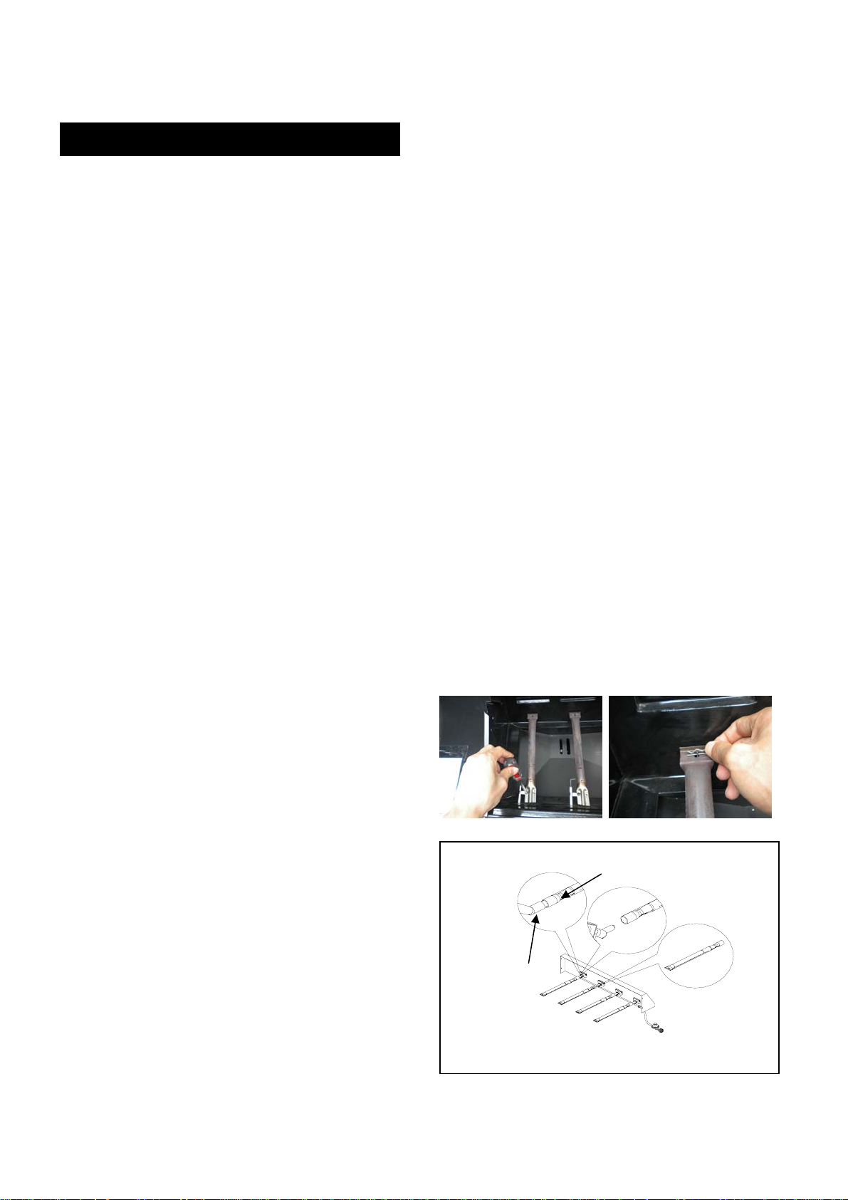
4. Remove the screws from the underside of each burner
and lift the burners up and away from the gas valve orifice.
5. Using a bent stiff wire in the shape of a hook , air hose
or a bottle brush, run it through the burner tube and inside
several times to remove any debris.
6. Replace burners, see illustration below.
Step 1. Remove screw which locks ig nite wire.
Step 2. Take off R clip which fixes burner at the end side.
Step 3. Locate the new burner onto the orifice.
(a) Insert the burner over the main burner gas valve .
(b) Make sure the orifice stud (C1) is inside the burner
venture (D1) as shown in (Fig.2 1).
Step 4. Secure the main burner on the back wall use R
clip, and fix on ignite wire.
Fig. 21
D1
Cleaning Exterior Surface
We suggest you wash your grill using a mild soap and
warm water solution. You can use a wash cloth or
sponge for this process. Do not use abrasives or a
brush that might remove finish during the cleaning
process.
C1
18
Page 19
!
WARNING
The location of the burner tube with respect to the
orifice is vital for safe operation. Check to ensure the
orifice is inside the burner tube before using the gas
grill. If the burner tube does not fit over the valve
orifice, lighting the burner may cause explosion
and/or fire.
2. Clean any clogged ports with a stiff wire, such as
an open paper clip.
3. Inspect each burner for damage (cracks or holes)
and if such damage is found, order and install a new
burner. After installation check to ensure that gas
valve orifices are correctly placed inside the ends of
the burner tubes.
Regardless of which burner cleaning procedure you
use, we recommend you also complete the following
steps to help prolong burner life.
1. Use a fiber pad or nylon brush to clean the entire
outer surface of each burner until free of food residue
and dirt.
Spiders and insects can nest inside the burners of
the grill and disrupt gas flow. This very dangerous
condition could cause a fire behind the valve panel,
thereby damaging the grill and making it unsafe
for operation. Inspect the grill at least twice a year.
WARNING
!
Troubleshooting
BEFORE CALLING FOR SERVICE
If the grill does not function properly, use the following check list before calling for service.
You should inspect the burners at least once a year or immediately after any of the following
conditions occur:
PROBLEMS WHAT TO DO
Grill won’ t l i ght when t he cont rol knob i s
rotated.
Check t o see i f LP t ank i s em pt y.
Clean wires and/or electrode by rubbi ng
with al cohol and cl ean swab.
W i pe with dry cl oth.
Mak e sure t he wire i s c onnected t o
elec t rode assembl y.
Do other burners on the uni t operate?
Check t o see i f ot her burners operate. If
so, c heck t he gas ori fice on t he
malfunc tioni ng burner for an obst ruct i on.
Burner flam e i s y el l ow or orange, i n
com bi nati on with t he odor of gas .
Refer to Clean Burner Tubes and Burner
Port s on page 19. If problem st i l l exists ,
pleas e cal l 1-800-913-8999.
Low heat with k nob in “HI” posi t i on. Is t he fuel hose bent or ki nked?
Is t he gri l l i n a dust y area?
Is t here adequate gas suppl y available?
If it is onl y one burner t hat appears l ow,
does the orifice or burner need c l eani ng?
Is t he gas supply or gas pres sure l ow?
19
Page 20
Cooking Instructions
WARNING
!
Do not leave the grill unattended.
Your grill will get very hot. Never lean over
the cooking area while using your grill. Do not
touch cooking surfaces, grill housing. Grill Lid
or any other grill parts while the grill is in
operation, or until the grill has cooled down
after use. Failure to comply with these
instructions may result in serious bodily injury.
Burn-off
Before cooking on your gas grill for the first time,
you will want to “burn off” the grill to eliminate any
odor or foreign matter. Just ignite the burners,lower
the Lid, and operate grill on the HIGH setting for 3 to
5minutes.
Cooking Temperatures
High setting: Only use this setting for fast warm-
up,searing steaks or chops and for burning food
residue off the grill after cooking is complete. Never
use the HIGH setting for extended cooking.
Indirect Cooking
To cook indirectly, the food should be placed on
the left or right side of your grill with the burner lit
on the opposite side.
Flare-ups
The fats and juices dripping from grilled food can
cause flare-ups. Since flare-ups impart a
favorably,distinctive taste and color to food cooked
cover an open flame, they should be accepted up
to a point. Nevertheless, uncontrolled flaring can
result in a ruined meal.
Medium to Low Settings: Most recipes specify
medium to low settings, including all smoking,
rotisserie cooking and for cooking lean cuts such as
fish.
NOTE: Temperature settings will vary with the
temperature and the amount of wind outside your
home.
Direct Cooking
The direct cooking method can be used with the
supplied cooking grids and food placed directly over
the lit grill Burners. The method is ideal for searing
and whenever you want meat, poultry or fish to have
and open-flame barbecued taste. Deep frying and
smoking are also best cooked in this manner
because they require direct heat.
WARNING
!
Do not line the bottom of the grill housing with
aluminum foil, sand or any substance that will
restrict the flow of grease into the grease tray.
Failure to comply with these instructions could
result in a fire or explosion which could ca us e
serious bodily injury, death, or property
damage.
20
Page 21
Grill Cooking Chart
Warning: To ensure that it is safe to eat, food must be cooked to the minimum internal
temperatures listed in the table below.
TemperatureFood
63°C (145°F)Beef, veal and lamb (pieces and whole cuts) - medium-rare
71°C (160°F)Beef, veal and lamb (pieces and whole cuts) - medium
77°C (170°FBeef, veal and lamb (pieces and whole cuts) - well done
71°C (160°F)Pork (pieces and whole cuts)
74°C (165°F)Poultry (e.g. chicken, turkey, duck) - pieces
85°C (185°F)Poultry -whole
Ground meat and meat mixtures (e.g. burgers, sausages, meatballs,
meatloaf, casseroles) - beef, veal, lamb and pork
From:Canadian Food Inspection Agency
71°C (160°F)
74°C (165°F)Ground meat and meat mixtures -poultry
74°C (165°F)Egg dishes
74°C (165°F)Others (hot dogs, stuffing and leftovers)
FOOD Weight or t hi ckness Temperature Time Special i nstr uct i ons and tips
Vegetabl es NA Medium 8 to 20 mi nut es
Potatoes Whol e Medium 40 to 60 mi nutes
Meat/St eaks 1/2 to 3/4 inc hes High-Medium 4 to 15 minutes
Ground Meats 1/2 to 3/ 4 i nc hes Medium 8 t o 15 m i nut es
Ribs 1/2 or full rack Medium 20 to 40 minut es
Hot dogs NA Medium 5 to 10 mi nut es
Poult ry -Cut 1/4 to 1/2 pounds Low or Medium 20 t o 40 m i nut es
Low or 1 to 1-1/ 2 hours
Poult ry W hol e 2 t o 3 pounds
Medium 40 to 60 mi nut es
Slice or chop vegetables and dot wi t h but ter or
margarine. Wrap tightly in heavy duty foil. Grill
turning occassionally.
Wrap indi vidually i n heavy duty foil . Cook
rotating occassionally.
Pre heat grill for 15-20 minutes then sear
st eak s on each side for two mi nut es. Nex t
grill 3 to 5 minutes on each side or until
desired donenes s.
Grill turning once when juices rise to the
surface or unti l des i red amount of doneness.
Do not leave hamburgers unattended s i nc e a
flare-up could occur quic kly .
Grill turning occassionally. During last few
minut es brush with barbec ue s auce, t urn
several times.
Grill turning four times. 2-4 minutes on each of
four sides.
Grill turning occassionally. During last few
minut es brush with barbec ue s auce if desi red,
turn several times.
Use poult ry stand and brus h frequently as
desired
Use poult ry stand and brus h frequently as
desired
Fis h 3/4 to 1 inch Medium 8 to 15 mi nutes
21
Grill turning once to desired doneness. Brus h
with mel t ed but ter, m argarine or oil.
 Loading...