


Electric Dryer
Secadora Electrica
riA I
8519319A
Sears Roebuck and Co., Hoffman Estates, IL 60179 U.S.A.
vuww.sears.com

TABLE OF CONTENTS
PROTECTION AGREEMENTS....................................................2 EE Ml ENT'S
WARRANTY
PEDESTAL OPTION WARRANTY................................................3 Master Protection Agreements
DRYER SAFETY........................................................................ 4 Congratulations on making a smart purchase. Your new
INSTALLATION INSTRUCTIONS ^ Kenmore®appliance is designed and r^anufactured for years of
I oois ana parts..........................................................................o preventive maintenance or repair from time to time. That’s when
Optional Pedestal.......................................................................5 having a Master Protection Agreement can save you money and
Location Requirements ............................................................5 aggravation.
Electrical Requirements..........................................................7
Electrical Connection
Venting Requiranents...............................................................12 yourself from unexpected hassle and expense.
Plan Vent System
Install Vent System
Install Leveling Legs.................................................................14 your new appliance. Here’s what’s included in the Agreement:
Level Dryer............................................................................14
Connect Vent 15 Expert service by our 12,000 professional repair specialists
Reverse Door Swing
Complete Installation................................................................16 covered repairs
FEATURES AND BENEFITS
Automatic Temperature Control
Jeans Cycle..............................................................................17 months
Ultra Delicate............................................................................17 ,/ Product replacement if your covered product can’t be fixed
DRYER USE..............................................................................
Starting Your Dryer
StoDoina Your Drver.............................................................18
n ✓ Fast help by phone - non-technical and instmctional
Control Locked.........................................................................18 repair scheduling
Loading.................................................................................18
Drying and Cycle Tips 19 Power surge protection against electrical damage due to
Status Lights
Cycles.....................................................................................19 ✓ Rental reimbursement if repair of your covered product takes
Options.....................................................................................20 longer than promised
Modifiers
Changing Cycles, Options and Modifiers
End of Cycle Signal..................................................................21 night, or schedule a service appointment online.
TUMBLE FREE^M Heated Dryer Rack
DRYER CARE......................................................................... 22 access to over 4.5 million quality parts and accessories. That’s
Cleaning the Dryer Location.....................................................22 the kind of professionalism you can count on to help prolong the
rMeaninn thn I int 'ii-raen 00 life of vour new purchase for years to come. Purchase vour
aeanlng She hS:;:::::::::::::::::::: S Master Protectkin Agreemen/todayl '
Removing Accumulated Lint
Vacation and Moving Care.......................................................23 information call 1 -800-827-^55.
Changing the Drum Light
TROUBIESHOOTING.
SERVICE NUMBERS.............................................BACK COVER appliances and items like garage door openers and water
........................................
.................................................................
.................................................................
..................................................................
..............................................................
..........
.................................................................
...........................................................................
................................................................................
....................................................
.......................................................
............................................................ 23 Installation Servi№
.......................................3
........................................ 17 ✓ “No-lemon” guarantee - replacement of your covered
...............................................
.................................
....................................
dependable operation. But like ali products, it may require
8 Purchase a Master Protection Agreement now and protect
12
14 j|.^g Master Protection Agreement also helps extend the life of
15 Unlimited service and no charge for parts and labor on ali
17 product if more than three product failures occur within twelve
17 ^ Annual Preventive Maintenance Check at your request - no
17 extra charge
assistance on products repaired in your home, plus convenient
19 P°^er fluctuations
21 Once you purchase the Agreement, a simple phone call is all that
21 ¡t takes for you to schedule service.You csn call anytime day or
21 Sears has over 12,000 professional repair specialists, who have
23 Some limitations and exclusions apply. For prices and
23 . .
For Sears guaranteed professional installation of home
heaters, in the U.S.A. call 1-800-4-MY-HOME®.
PROTECTION

WARRANTY
PEDESTAL OPTION
Full One-Year Warranty on Mechanical and Electrical Parts
For one year from the date of purchase, when this dryer is
installed and operated according to the instructions provided in
this Use and Care Guide, Sears will repair this dryer, free of
charge, if defective in materials or workmanship.
NOTE: Exhausting this dryer with a plastic vent can void this
warranty. See “Installation Instructions” for the complete exhaust
requirements for this dryer.
Limited Two-Year Warranty on SENSOR SMAFiT™
Electronic Control Board
For the second year from the date of purchase, Sears will replace
the electronic control board if defective in material or
workmanship. You will be charged for labor after the first year.
Wairanty Restriction
If the dryer is subject to other than private family use, the above
warranty coverage is effective for only 90 days.
Wairanty Service
Warranty service is available by contacting the nearest Sears
Service Center. This warranty applies only while the product is in
use in the United States.
This wairanty gives you specific legal rights and you may also
have other rights which vary from state to state.
For Sears Warranty information or to contact a Sears Service
Center, please refer to the service numbers located on the back
page of this manual.
Sears, Roebuck and Co.
D/817WA, Hoffman Estates, IL60179
V\/ARR^NTY
Full One-Year Wairanty on Mechanical Parts
For one year from the date of purchase, supplier will repair or
replace any of its mechanical parts if defective in material or
workmanship. This Pedestal must be installed with this dryer
according to the instmctlons provided In the Pedestal Installation
Instructions.
Warranty Restriction
If the Pedestal is subject to other than private family use and/or
used with any other product than those listed in the installation
instructions, this warranty is null and void.
In the space following, record your complete model number,
serial number, and purchase date.You can find this information
on the model and serial number label.
Have this information available to help you quickly obtain
assistance or service when you contact Sears concerning your
appliance.
Model number 110.
Serial number_
Purchase date
Save these instructions and your sales receipt for future
reference.
Product Record
In the space following, record your complete model number,
serial number, and purchase date. You can find this Information
on the mode! and serial number label, located at the top inside
dryer door well.
Have this information available to help you quickly obtain
assistance or service when you contact Sears concerning your
appliance.
Model number 110._____________________________________________
Serial number
Purchase date_________________________________________________
Save these instructions and your sales receipt for future
reference.
_________________________________________________
DRYER SAFETY
Your safety and the safety of others are very important.
We have provided many important safety messages in this manual and on your appliance. Always read and obey all
safety messages.
This is the safety alert symbol.
This symbol alerts you to potential hazards that can kill or hurt you and others.
All safety messages will follow the safety alert symbol and either the word “DANGER” or
“WARNING.” These words mean:
You can be killed or seriously injured if you don't
ADANGER
AWARNING
All safety messages will tell you what the potential hazard is, tell you how to reduce the chance of injury, and tell you
what can happen if the instructions are not followed.
IMPORTANT SAFETY INSTRUCTIONS
WARNING: To reduce the risk of fire, electric shock, or injury to persons when using the dryer, follow basic
precautions, including the following:
immediately follow instructions.
You can be killed or seriously injured if you don't follow instructions.
Read all instructions before using the dryer.
Do not place items exposed to cooking oils in
your dryer. Items contaminated with cooking oils
may contribute to a chemical reaction that could
cause a load to catch fire.
Do not dry articles that have been previously
cleaned in, washed in, soaked In, or spotted with
gasoline, dry-cleaning solvents, other flammable,
or explosive substances as they give off vapors
that could ignite or explode.
Do not allow children to play on or in the dryer.
Close supervision of children is necessary when
the dryer is used near children.
Before the dryer is removed from service or dis
carded, remove the door to the drying compart
ment.
Do not reach into the dryer if the drum is moving.
Do not install or store the dryer where it will be
exposed to the weather.
Do not tamper with controls.
SAVE THESE INSTRUCTIONS
Do not repair or replace any part of the dryer or
attempt any servicing unless specifically recom
mended in this Use and Care Guide or in published
user-repair instructions that you understand and have
the skills to carry out.
Do not use fabric softeners or products to eliminate
static unless recommended by the manufacturer of
the fabric softener or product.
Do not use heat to dry articles containing foam rubber
or similarly textured rubber-like materials.
Clean lint screen before or after each load.
Keep area around the exhaust opening and adjacent
surrounding areas free from the accumulation of lint,
dust, and dirt.
The interior of the dryer and exhaust vent should be
cleaned periodically by qualified service personnel.
See installation instructions for grounding require
ments.

INSTALLATION
INSTRUCTIONS
Check that you have everything necessary for correct installation.
Proper installation is your responsibility.
Are you placing the dryer on a pedestal? You can purchase a
pedestal separately for this dryer. TTiis pedestal will add about
14 in. (35.56 cm) to the height of your unit for a tota! height of
approximately 52 in. (132.08 cm).
Flat-blade screwdriver
Adjustable wrench that
opens to 1 in. {2.54 cm)
or hex-head socket
wrench (for adjusting
dryer feet)
Level
Wire stripper (direct wire
installations)
#2 Phillips screwdriver
Parts supplied
Remove parts package from dryer drum. Check that all parts are
included.
4 Leveling legs
NOTE: Do not use leveling legs if installing the dryer on a
pedestal.
Parts needed
Check local codes. Check existing electrical supply and venting.
See “Electrical Requirements” and “Venting Requirements”
before purchasing parts.
■ For close-clearance installations between 31.5 in. (80.01 cm)
and 37 in. (93.98 cm), see “Plan Vent System” section for
venting requirements.
Safety glasses
Duct tape
Caulking gun and
compound (for installing
new exhaust vent)
Gloves
Tin snips (new vent
installations)
V4 in. nut driver or socket
wrench
The pedestal is available in three colors
White - Part Number 42842
Biscuit - Part Number 42844
Graphite - Part Number 42846
To order, call your local Sears store. For further information,
please call 1-800-4-MY-HOME® (1-800-469-4663).
Location Reciuiremerits
AWARNING
Explosion Hazard
Keep flammable materials and vapors, such as
gasoline, away from dryer.
Place dryer at least 18 inches (46 cm) above the
floor for a garage installation.
Failure to do so can result in death, explosion,
or fire.
•*: 37" ►
(S3.9B cm)
Mobile home installations require meta! exhaust system hardware
available for purchase from your local Sears store or Sears
Service Center. For further information, please call
1-800-4-MY-HOME® (1 -800-469-4663).
You will need
■ A location that allows for proper exhaust installation. See
“Venting Requirements.”
■ A separate 30 amp circuit.
■ A grounded electrical outlet located within 2 ft (61 cm) of
either side of the dryer. See “Electrical Requirements.”
■ A sturdy floor to support the total dryer weight of 200 lbs
(90.7 kg). The combined weight of a companion appliance
should also be considered.
■ A level floor with a maximum slope of 1 in. (2.5 cm) under
entire dryer. (If slope is greater than 1 In. [2.5 cm], install
Extended Dryer Feet Kit, Part No. 279810.) Clothes may not
tumble properly and automatic sensor cycles may not
operate correctly if dryer is not level.

■ For a garage installation, you will need to place the dryer at
least 18 in. {46 cm) above the floor. If using a pedestal, you
will need an additional 6 in. (15.24 cm).
Do not operate your dryer at temperatures below 45“F (7°C). At
lower temperatures, the dryer might not shut off at the end of an
automatic cycle. Drying times can be extended.
Install the dryer where it is protected from water and/or weather.
Check code requirements. Some codes iimit, or do not permit,
installation of the dryer in garages, closets, mobile homes, or
sleeping quarters. Contact your local building inspector.
Installation clearances
The location must be large enough to fully open the dryer door.
Dryer Dimensions
Closet installation - Dryer only
1. Side view - closet or confined area
2. Closet door with vents
Recessed or closet installation - Dryer on pedestal
* Most installations require a minimum 5y2 in. (14 cm) clearance
behind the dryer for the exhaust vent with elbow. See 'Venting
Requirements.”
Minimum installation spadng for recessed area, custom
undercounter or closet installation
The following dimensions shown are for the minimum spacing
allowed.
■ Additional spacing should be considered for ease of
installation and servicing.
■ Additional clearances might be required for wall, door and
floor moldings.
■ Additional spacing of 1 in. (2.5 cm) on all sides of the dryer is
recommended to reduce noise transfer.
■ For closet installation, with a door, minimum ventilation
openings in the top and bottom of the door are required.
Louvered doors with equivalent ventilation openings are
acceptable.
■ Companion appliance spacing should also be considered.
Custom undercounter installation - Dryer only
1. Recessed Area
2. Side view - cioset or confined area
Mobile home-additional installation requirements
This dryer is suitable for mobile home installations.
The installation must conform to the Manufactured Home
Construction and Safety Standard, Title 24 CFR, Part 3280
(formerly the Federal Standard for Mobile Home Construction
and Safety, Title 24, HUD Part 280).
Mobile home installations require;
■ Metal exhaust system hardware which is avaiiabie for
purchase from your iocal Sears store or Sears Service Centa".
■ Special provisions must be made in mobiie homes to
introduce outside air into the drya. The opening (such as a
nearby window) should be at ieast twice as large as the dryer
exhaust opening.

MM
H: is your responsibility
■ To contact a qualified electrical installer.
■ To be sure that the electrical connection is adequate and in
conformance with the National Electrical Code, ANSI/NFPA
70-latest edition and all local codes and ordinances.
A copy of the above code standards can be obtained from:
National Fire Protection Association, Batterymarch Park,
Quincy, MA 02269.
■ To supply the required 3 or 4 wire, single phase, 120/240-volt,
60-Hz., AC-only electrical supply (or 3 or 4 wire, 120/208-volt
electrical supply, if specified on the seriai/rating plate) on a
separate 30-amp circuit, fused on both sides of the line. A
time-delay fuse or circuit breaker is recommended. Connect
to an individual branch circuit. Do not have a fuse in the
neutral or grounding circuit.
■ Do not use an extension cord.
■ If codes permit and a separate ground wire is used, it is
recommended that a quaiified eiectrician determine that the
ground path is adequate.
Electrical Connection
To properly install your dryer, you must determine the type of
electrical connection you will be using and follow the instructions
provided for it here.
■ If local codes do not permit the connection of a cabinet
ground connector to the neutral wire, see “Optional 3-wire
connection” section.
■ This dryer is manufactured with a 3-wire, cabinet-ground
conductor connected to the NEUTRAL {white or center wire)
of the wiring harness at the terminai block.
■ Use a 4-wire conductor cord when the dryer is instailed in a
mobiie home or an area where locai codes do not permit
grounding through the neutral.
If your outlet looks like this:
3-wire receptacle (10-30R)
Then choose a 3-wire power supply cord with ring or spade
terminals and UL approved strain relief. The 3-wire power supply
cord, at least 4 ft (1.22 m) long, must have 3, No.-10 copper wires
and match a 3-wire receptacle of NEMA Type 10-30R.
If connecting by direct wire:
Power supply cable must match power supply (4-wire or 3-wire)
and be:
■ Flexible armored cable or non-metallic sheathed copper
cable (with ground wire), protected with flexible metallic
conduit. All current-carrying wires must be insulated.
■ 10 gauge solid copper wire (do not use aluminum).
■ At least 5 ft (1.52 m) long.
GROUNDING INSTRUCTIONS
■ For a grounded, cord-connected dryer:
This dryer must be grounded, in the event of malfunction
or breakdown, grounding will reduce the risk of electric shock
by providing a path of least resistance for electric current. This
dryer uses a cord having an equipment-grounding
conductor and a grounding plug. The plug must be plugged
into an appropriate outlet that is properly installed and ground
ed in accordance with ail locai codes and ordinances.
■ For a permanently connected dryer:
This dryer must be connected to a grounded metal, permanent
wiring system, or an equipment-grounding conductor must be
run with the circuit conductors and connected to the equip
ment-grounding terminal or lead on the dryer.
If using a power supply cord:
Use a UL approved power supply cord kit marked for use with
ciothes dryers. The kit shouid contain:
■ A UL approved 30 amp power suppiy cord, rated 120/240
volt minimum. The cord should be type 3RD or SRDT and be
at least 4 ft (1.22 m) long. The wires that connect to the dryer
must end in ring terminals or spade temninals with upturned
ends.
■ A UL approved strain relief.
If your outlet looks like this:
4-wire receptacle (14-30R)
Then choose a 4-wire power supply cord with ring or spade
terminals and UL approved strain reiief. The 4-wire power supply
cord, at least 4 ft (1.22 m) long, must have 4,10 gauge solid
copper wires and match a 4-wire receptacie of NEMA Type
14-30R. TTie ground wire (ground conductor) may be either green
or bare. The neutral conductor must be identified by a white
cover.
WARNING: Improper connection of the equipment
grounding conductor can result in a risk of electric shock.
Check with a qualified electrician or service representative or
personnel if you are in doubt as to whether the dryer is proper
ly grounded. Do not modify the plug on the power supply cord:
if it will not fit the outlet, have a proper outlet installed by a
qualified electrician.
SAVE THESE INSTRUCTIONS
Eteotricai Connection
Power Supply Cord
Direct Wile
ikWARNING AWARNING
M
Fire Hazard
Use a new UL approved 30 amp power
supply cord.
Use a UL approved strain relief.
Disconnect power before making electrical
connections.
Connect neutral wire (white or center wire) to center terminal (silver).
center terminal (silver).
Ground wire (green or bare wire) must be
connected to green ground connector.
Connect remaining 2 supply wires to remaining 2 terminals (gold).
2 terminals (gold).
Securely tighten all electrical connections.
Failure to do so can result in death, fire, or
electrical shock.
Use 10 gauge solid copper wire.
Use a UL approved strain relief.
Disconnect power before making electrical
connections.
Connect neutral wire (white or center wire) to
Ground wire (green or bare wire) must be
connected to green ground connector.
Connect remaining 2 supply wires to remaining
Securely tighten all electrical connections.
Failure to do so can result in death, fire, or
electrical shock.
M,
Fire Hazard
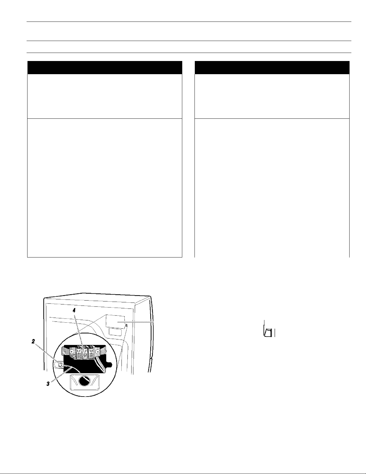
1. Disconnect power.
2, Remove the hold-down screw and temninal block cover.
7. Terminal block cover and hold down screw
2. External ground connector
3. Neutral grounding wire (green/yellow)
4. Center, silver-colored terminal-block screw
3. Assemble a % in. (1.9 cm) UL approved strain relief (UL
marking on strain relief) into the hole below the terminal block
opening. Tighten strain reiief screws just enough to hold the
two clamp sections together. Put power supply cord through
the strain relief. TTie strain reiief should have a tight fit with the
dryer cabinet and be in a horizontai position.
4. Now complete Installation following instructions for your type
of electrical connection:
4-wire (recommended)
3-wire (if 4-wlre Is not available)

Electrical Connection Options
If your home has: And you will be
Go to Section
connecting to:
4-wire receptacle
(NEMA Type 14-30R)
A UL listed,
120/240 volt
4-wire connection:
Power supply cord
minimum, 30
amp, dryer
power supply
cord*
4-wire direct A fused 4-wire connection:
_________
disconnect or Direct Wire
circuit breaker
**" ¡Tz.7 cm) ^
3-wire receptacle
(NEMA type 10-30R)
box*
A UL listed,
120/240 volt
3-wire connection:
Power supply cord
minimum, 30
amp., dryer
power supply
cord*
3-wire direct A fused
disconnect or
3-wire connection:
Direct Wire
circuit breaker
box*
1. Remove center terminal block screw.
2. Remove appliance ground wire (green with yellow stripes)
from external ground connector screw. Fasten it under center,
silver colored terminal block screw.
1. External ground connector - Dotted line shows
position of NEUTRAL ground wire before being
moved to center termini block screw
2. Center silver-colored terminal block screw
3. Green/yellow wire of harness
3. Connect ground wire (green or bare) of power supply cord to
external ground conductor screw. Tighten screw.
4. Connect neutral wire (white or center wire) of power supply
cord under center screw of the terminal block.
*lf local codes do not permit the connection of a frame-grounding
conductor to the neutral wire, go to “Optional 3-wire
Connection" section.
4-wire connection: Power supply cord
IMPORTANT: A 4-wire connection is required for mobile homes
and where local codes do not permit the use of 3-wire
connections.
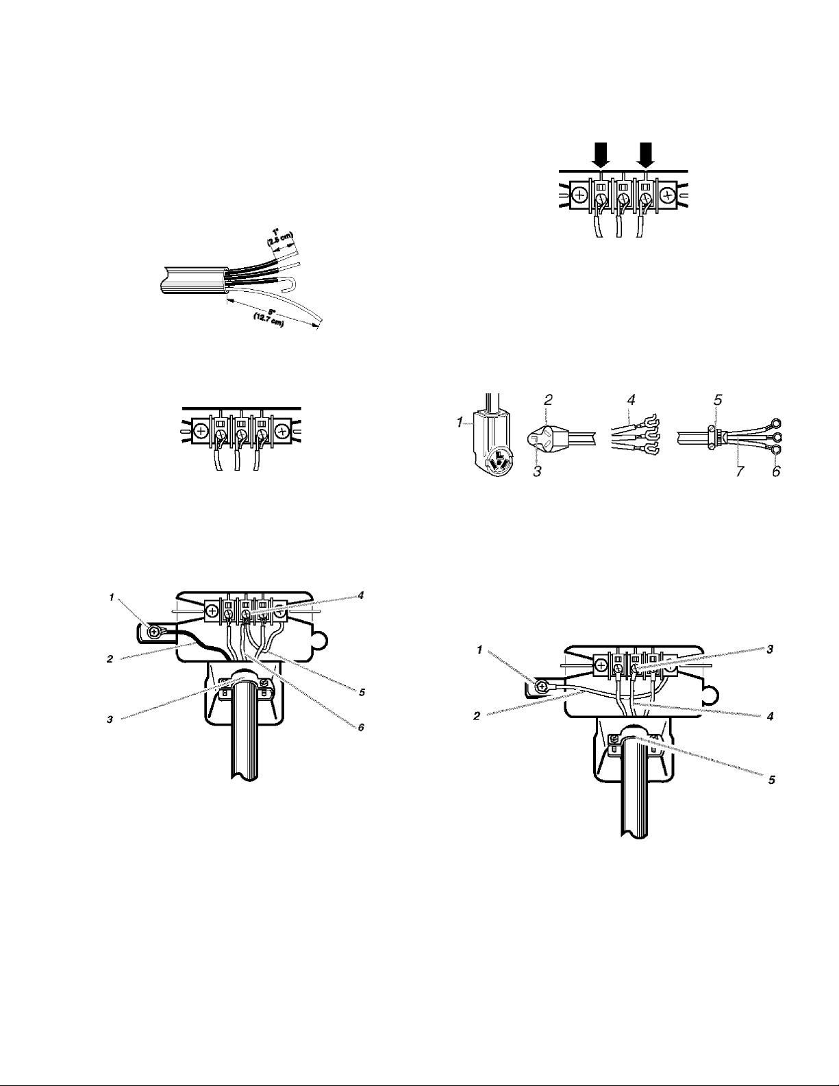
7. 4-wirB rBCBptaclB (NEMA type 14-30R)
2. 4-prong plug
3. Ground prong
4. Neutral prong
5. SpadB terminals with upturned ends
6. % in. (1.9 cm) UL approved strain relief
7. Ring terminals
1. External ground connector
2. Green or bare copper wire of power supply cord
3. ¥4 in. (1.9 cm) UL-listed strain relief
4. Center silver-colored terminal block screw
5. Neutral grounding wire (green/yellow)
6. Neutral wire (white or center wire)
5.
Connect the other wires to outer terminal block screws.
Tighten screws.
6.
Tighten strain relief screws.
7.
Insert tab of terminal block cover into slot of dryer rear panel.
Secure cover with hold-down screw.
4-wire connection; Direct wire
IMPORTANT: A 4-wire connection is required for mobile homes
and where local codes do not permit the use of 3-wire
connections.
Direct wire cable must have 5 ft (1.52 m) of extra length so dryer
can be moved if needed.
Strip 5 in. (12.7 cm) of outer covering from end of cable, leaving
bare ground wire at 5 in. (12.7 cm). Cut 114 in. (3.8 cm) from 3
remaining wires. Strip insuiation back 1 in. (2.5 cm). Shape ends
of wires into a hook shape.
4.
Place the hooked end of the neutral wire (white wire) of power
supply cable under the center screw of terminal block (hook
facing right). Squeeze hooked end together. Tighten screw.
5.
Place the hooked ends of the other power supply cable wires
under the outer temninal block screws (hooks facing right).
Squeeze hooked ends together. Tighten screws.
6. Tighten strain relief screws.
7. Insert tab of terminal block cover into slot of dryer rear panel.
Secure cover with hold-down screw.
3-wire connection: Pow®- ^pply cord
When connecting to the terminal block, place the hooked end of
the wire under the screw of the terminal block (hook facing right),
squeeze hooked end together and tighten screw. See example
below.
1.
Remove center terminal block screw.
2,
Remove appliance ground wire (green with yellow stripes)
from external ground connector screw. Fasten it under center,
silver colored terminal block screw.
3.
Connect ground wire (green or bare) of power supply cable to
external ground conductor screw. Tighten screw.
Use where local codes permit connecting cabinet-ground
conductor to neutral wire.
7. 3-wire receptacle (NEMA type 10-30R)
2. 3-wire plug
3. Neutral prong
4. Spade terminals with up turned ends
5. %in. (1.9 cm) UL approved strain relief
6. Ring terminals
7. Neutral (white or center wire)
1. Loosen or remove center terminal block screw.
2. Connect neutral wire (white or center wire) of power supply
cord to the center, silver colored terminal screw of the
terminal block. Tighten screw.
10
7. External ground connector
2. Green or bare copper wire of power supply cord
3. %in. (1.9 cm) UL-iisted strain relief
4. Center silver-colored terminal block screw
5. Neutral grounding wire (green/yeliow)
6. Neutral wire (white or center wire)
1. External ground connector
2. Neutral grounding wire (green/yeliow)
3. Center silver-colored terminal block screw
4. Neutral wire (white or center wire)
5. ¥4 in. (1.9 cm) UL-iisted strain relief
3.
Connect the other wires to outer terminal block screws.
Tighten screws.
4.
Tighten strain relief screws.
5.
Insert tab of terminal block cover into slot of dryer rear panel.
Secure cover with hold-down screw.

3-wire connection; Direct wire
Optional 3-wire connection
Use where local codes permit connecting cabinet-ground
conductor to neutral wire.
Direct wire cable must have 5 ft (1.52 m) of extra length so dryer
can be moved if needed.
Strip 3V2 in. (8.9 cm) of outer covering from end of cable. Strip
insulation back 1 in. (2.5 cm). If using 3-wire cable with ground
wire, cut bare wire even with outer covering. Shape ends of wires
into a hook shape.
When connecting to the terminal block, place the hooked end of
the wire under the screw of the terminal block (hook facing right),
squeeze hooked end together and tighten screw. See example
below.
1.
Loosen or remove center temninal block screw.
2.
Place the hooked end of the neutral wire (white or center wire)
of power supply cable under the center screw of terminal
block (hook facing right). Squeeze hooked end together.
Tighten screw.
Use for direct wire or power supply cord where local codes
do not permit connecting cabinet-ground conductor to
neutral wire.
1.
Remove center terminal block screw.
2.
Remove appliance ground wire (green with yellow stripes)
from external ground connector screw. Connect appliance
ground wire and the neutral wire (white or center wire) of
power supply cord/cabie under center, silver colored terminal
block screw. Tighten screw.
3.
Connect the other wires to outer terminal block screws.
Tighten screws.
4. Tighten strain relief screws.
5. Insert tab of terminal block cover into slot of dryer rear panel.
Secure cover with hold-down screw.
6. Connect a separate copper ground wire from the external
ground connector screw to an adequate ground.
7. Extern^ ground connector
2. Neutral grounding wire (green/yellow)
3. Center sUver-coiored terminal block screw
4. Neutral wire (white or center wire)
5. %in. (1.9 cm) UL-iisted strain relief
3.
Place the hooked ends of the other power supply cable wires
under the outer terminal block screws (hooks facing right).
Squeeze hooked ends together. Tighten screws.
f t
4, Tighten strain relief screws.
5. Insert tab of terminal block cover into slot of dryer rear panel.
Secure cover with hoid-down screw.
7. External ground connector
2. Neutral grounding wire (green/yellow)
3. Neutral wire (white or center wire)
4. Grounding path determined by a
qualified electrician
11

fi illfi i€ii ii
^WARNING
Fire Hazard
Use a heavy metal vent.
Do not use a plastic vent.
Do not use a metal foil vent.
Failure to follow these instructions can result in
death or fire.
WARNING: To reduce the risk of fire, this dryer MUST BE
EXHAUSTED OUTDOORS.
Exhaust hood must be at least 12 in. (30.5 cm) from the ground or
any object that may be in the path of the exhaust (such as
flowers, rocks or bushes, etc.).
If using an existing vent system, clean lint from the entire length
of the system and make sure exhaust hood is not plugged with
lint. Replace any plastic or metal foil vent with rigid metal or
flexible metal vent.
Oi
Typical exhaust installations
Typical Installations vent the dryer from the rear of the dryer.
Other Installations are possible.
4 in. (10.2 cm) heavy metai exhaust vent and ciamps must be
used. DURASAFE'^'^ venting products are recommended and are
available from your local Sears store or Sears Service Center.
DURASAFE^i^ vent products can be purchased from your deaier.
For further infomnation, please cali 1-800-4-MY-HOME®
(1-800-469-4663) or visit our Internet site at: www.sears.com.
■ The dryer exhaust must not be connected into any gas vent,
chimney, wall, ceiling, or a concealed space of a building.
■ Do not use an exhaust hood with a magnetic latch.
■ Do not install flexible metal vent In enclosed walls, ceilings or
floors.
■ Use clamps to seal all joints. Exhaust vent must not be
connected or secured with screws or other fastening devices
which extend into the interior of the duct. Do not use duct
tape.
IMPORTANT; Observe all governing codes and ordinances.
Improper venting can cause moisture and lint to collect indoors, which may result in:
■ Moisture damage to woodwork, furniture, paint, wall
paper, carpets, etc.
■ Housecieaning problems and health problems.
Use a heavy metal vent. Do not use plastic or metal foil vent.
Rigid metal vent is recommended to prevent cmshing and
kinking.
Flexible metal vent must be fully extended and supported when
the dryer is in its final position. Remove excess flexible metal vent
to avoid sagging and kinking that may result in reduced airflow
and poor performance.
An exhaust hood should cap the vent to prevent rodents and
insects from entering the home.
1. Dryer
2. Elbow
3. Wall
4. Exhaust hood
5. Clamps
6. Rigid metal or flexible metal vent
7. Vent length necessary to connect elbows
8. Exhaust outlet
Optional exhaust installations
This dryer can be converted to exhaust out the right side, left
side, or through the bottom.
AWARNING
Fire Hazard
Cover unused exhaust holes with one of the
following kits:
279818 (white)
279915 (graphite)
279925 (biscuit)
Contact your local dealer.
Failure to follow these instructions can result in
death, fire, electrical shock, or serious injury.
12
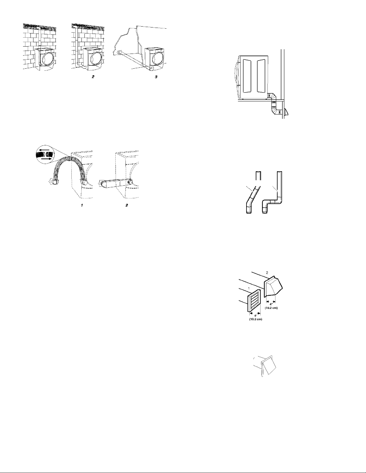
7. Standard rear offset exhaust installation
2. Left or right side exhaust instaliation
3. Bottom exhaust installation (Not an option with
pedestal installations.)
Alternate installations for close clearances
Venting systems come in many varieties. Seiect the type best for
your instaiiation. Twfo dose-clearance installations are shown.
Refer to the manufacturer’s instructions.
Special provisions for mobile home installations
The exhaust vent must be securely fastened to a noncombustible
portion of the mobile home structure and must not terminate
beneath the mobile home. Temninate the exhaust vent outside.
Determine Vent Length
1. Select the route that will provide the straightest and most
direct path outdoors. Plan the installation to use the fewest
number of elbows and turns. When using elbows or making
turns, allow as much room as possible. Bend vent gradually
to avoid kinking. Avoid 90° turns.
batter _ good
7. Over-The-Top installation (also available with one
offset elbovv)
2. Periscope installation
NOTE: The following kits for close clearance alternate
installations are available for purchase. For further information,
please call
1-800-4-MY-HOME®(1-8(X)-469-4663).
■ Over-The-Top Installation:
Part Number 26-49900
■ Periscope Installation (For use with dryer vent to wall vent
mismatch):
Part Number 26-49901 - Less than 5 in. (12.7 cm) mismatch
Part Number 26-49908 - 5 in. (12.7 cm) to 18 in. (45.72 cm)
mismatch
Part Number 26-49904 - 18 in. (45.72 cm) to 29 in. (73.66 cm)
mismatch
Part Number 26-49905 - 29 in. (73.66 cm) to 50 in. (127 cm)
mismatch
2. Determine vent length
The maximum length of the exhaust system depends upon:
■ The type of vent (rigid metal or flexible metal).
■ The number of elbows used.
■ Type of hood.
Recommended hood styles are shown here.
7. Louvered hood style
2. Box hood style
The angled hood style (shown following) is acceptable.
4 " >>
(10.2 CfflT
2Vi"
cm)
See the exhaust vent length chart that matches your hood
type for the maximum vent lengths you can use.
13

Exhaust systems longer than specified will:
■ Shorten the life of the dryer.
■ Reduce performance, resulting in longer drying times and
increased energy usage.
3. Determine the number of elbows you will need.
IMPORTANT: Do not use vent runs longer than specified in
the Vent Length Chart.
The chart below helps you determine your maximum vent
length based on the number of 90° turns or elbows you will
need and the type of vent (rigid or flexible metal) and hood
that you will use.
Vent Length Chart
Number of
90“ turns
or elbows
Type of
vent
Box or
Louvered
hoods
Angled
hoods
irisfc3llLe¥€3 3..:;:',::
^WARNING
Excessive Weight Hazard
Use two or more people to move and install
dryer.
Failure to do so can result in back or other injury.
1.
To protect the floor, use a large flat piece of cardboard from
the dryer carton. Place cardboard under the entire back edge
of the dryer. See illustration.
2.
Firmly grasp the body of the dryer (not the console panel).
0 Rigid metal
Flexible metal
1 Rigid metal
Flexible metal
2 Rigid metal
Flexible metal
3 Rigid metal
Flexible metal
4 Rigid metal
Flexible metal
NOTE: Side and bottom exhaust installations have a 90° turn
inside the dryer. To determine maximum exhaust length, add 1
90° turn to the chart.
64 ft (20 m)
36 ft (11 m)
54 ft (16.5 m)
31 ft (9.4 m)
44 ft (13.4 m)
27 ft (8.2 m)
35 ft (10.7 m)
25 ft (7.6 m)
27 ft (8.2 m)
23 ft (7 m)
58 ft (17.7 m)
28 ft (8.5 m)
48 ft (14.6 m)
23 ft (7 m)
38 ft (11.6 m)
19 ft (5.8 m)
29 ft (8.8 m)
17 ft (5.2 m)
21 ft (6.4 m)
15 ft (4.6 m)
itSysteiTi
1. (Optional) Put on safety glasses and gloves.
2, Install exhaust hood. Use caulking compound to seal exterior
wall opening around exhaust hood.
3. Connect vent to exhaust hood. Vent must fit inside exhaust
hood. Secure vent to exhaust hood with 4 in. (10.2 cm)
clamp.
4, Run vent to dryer location. Use the straightest path possible.
See “Determine Vent Length.” Avoid 90° turns. Use clamps to
seal all joints. Do not use duct tape, screws or other fastening
devices that extend into the interior of the vent to secure
vent.
Gently lay the dryer on the cardboard.
3. Examine the leveling legs. Find the diamond marking.
4.
Screw the iegs into the leg holes by hand. Use a wrench to
finish turning the legs until the diamond marking is no longer
visible.
5.
Place a carton corner post under each of the 2 dryer back
corners. Stand the dryer up. Slide the dryer on the corner
posts until it is close to its finai location. Leave enough room
to connect the exhaust vent.
6. Once connection is made and dryer is in final location,
remove corner posts and cardboard.
Í /■■xrel Í3ryer
Check the leveiness of the dryer. Check level ness first
side-to-side, then front-to-back.
14
If the dryer is not level, prop up the dryer using a wood block.
Use a wrench to adjust the legs up or down and check again for
levelness.
NOTE: It might be necessary to level the dryer again after it has
been moved into its final position.

III
1.
Using a 4 in. (10.2 cm) clamp, connect vent to exhaust outlet
in dryer. If connecting to existing vent, make sure the vent is
clean. The dryer vent must fit over the dryer exhaust outlet
and inside the exhaust hood. Make sure the vent is secured
to exhaust hood with a 4 in. (10.2 cm) clamp.
2.
Move dryer into final position. Do not crush or kink vent.
Make sure dryer is level.
3.
(On gas models) Check to be sure there a’e no kinks in the
flexible gas line.
You can change your door swing from a right-side opening to a
left-side opening, if desired.
Remove the door
1. Place a towel or soft cloth on top of the dryer or work space
to protect the surface.
2, Open the dryer door. Remove the 5 screws that hold the door
hinge on the front pane! of the dryer. Loosen, but do not
remove, the screw with the top keyhoie opening LAST (2nd
from the top).
Reverse th№ hinge and hinge cover
1. Place the inner door, screwhead side up, on the work space.
2. Gently pull the plastic cover out and down. This unsnaps the
plastic hinge cover from the inside door assembly.
3. Remove the 4 screws that hold the hinge to the door.
3.4,Lift and pull forward on the door so that the screwhead clears
the keyhole. Remove the door.
Lay the dryer door on a flat, protected surface with the inside
door assembly facing up. Remove the 6 screws to release the
outer door assembly from the inner door assembly, as
indicated below. See illustration. It is important that you
remove ONLY the 6 indicated screws.
5. Lift the inner door assembly off of the outer door assembly.
Set the outer door assembly aside.
4. Reverse the 2 large hole screw plugs to the opposite side and
insert in the original screw holes.
1. Hinge Screws
2. Hole screw plugs
5. Move hinge to the other side and reattach.
6. Reverse the plastic cover. Slide it up over the inner door
assembly edge and gently snap into place.
7. Set the inner door assembly aside.
15
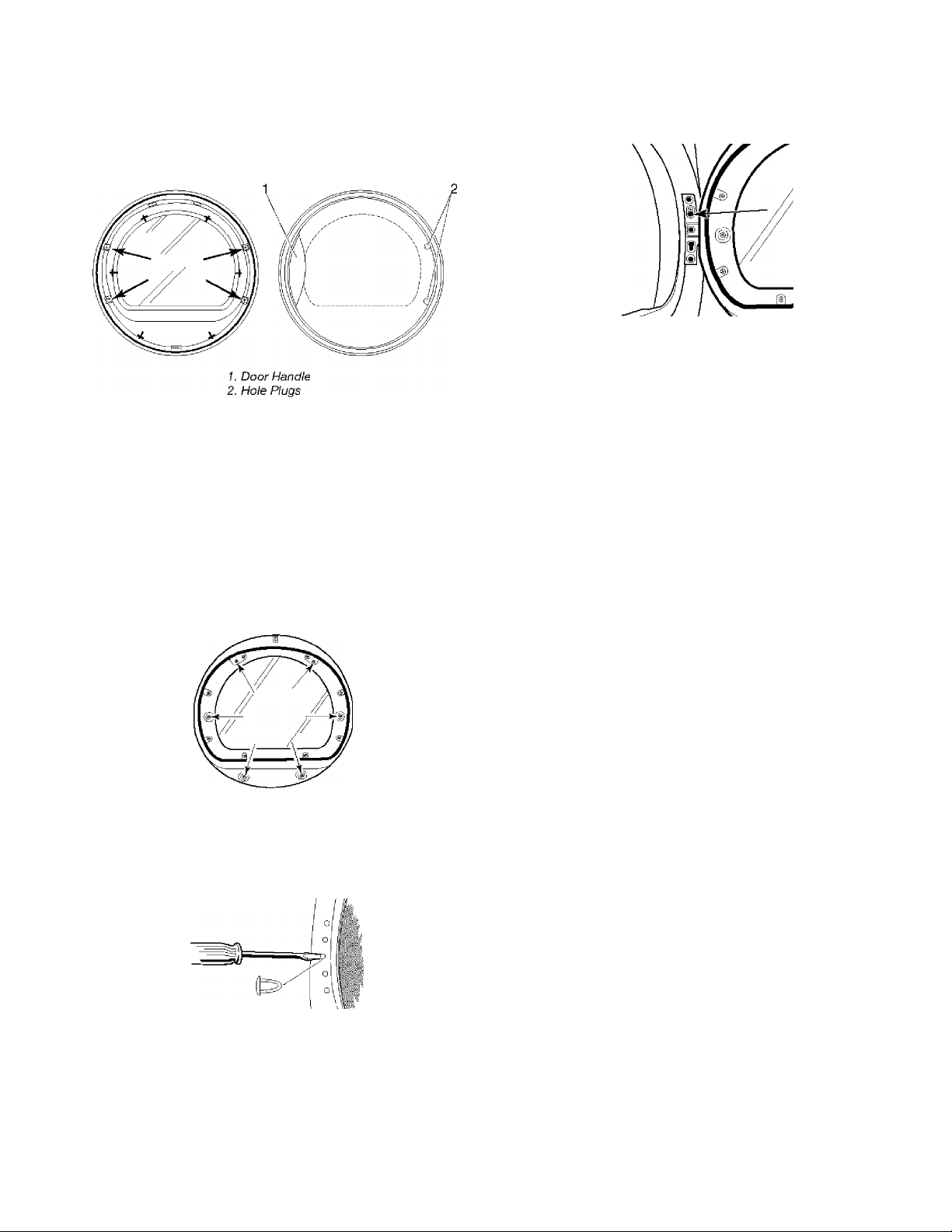
Reverse llie door handle
1. Place the outer door assembly face down on work space.
2, Remove the 2 screws that hold the door handle and the 2
screws holding the hole plugs. If hole plugs do not easily fall
out after screws are removed, insert a small screwdriver into
the holes and gently push the plugs out.
3.4.Move the door handle to the other side and reattach.
Move the hole plugs to the new hinge side and attach with
screws.
Reinstalling the door
1. Check for fingerprints on the glass. Clean if necessary.
2. Place the inner door assembly into the outer door assembly.
Align the hinge cover and hinge in the openings on each side.
To fit correctly, the inside door assembly edge is completely
inside the outside door assembly edge.
3. Reassemble the inner and outer door assemblies with the 6
screws.
4, Use a small flat-head screwdriver to remove hole plugs in the
door opening. Slide the head of the screwdriver under the
cap of each hole plug, being careful not to scratch the dryer
surface. Lift up. Remove the hole plugs in the door opening
and insert in the opposite side.
5.
Insert a screw in the 2nd opening from the top of the hinge
opening and partially tighten. Hang the door by placing the
top hinge keyhole over the 2nd screwhead and tighten the
screw. By putting this screw in first, the door wiil hang in
place while you insert and tighten the remaining 4 screws.
6. Close the door and check that it latches securely.
if laiciilcfliOf I
Check to be sure all parts are now installed. If there is an
extra part, go back through the steps to see which step was
skipped.
Check to be sure you have all of your tools.
Dispose of all packaging materials.
Check the dryer’s final location. Be sure the vent is not
crushed or kinked.
Check to be sure the dryer is level. (See “Level Dryer.”)
Plug into a grounded outlet. Turn power on.
Remove the blue protective film on the console and any tape
remaining on the dryer.
Read “Dryer Use.”
Wipe the dryer drum interior thoroughly with a damp cloth to
remove any dust.
10. Set the dryer on a full heat cycle (not an air cycle) for 20
minutes and start the dryer.
If the diyer will not start, check the following:
■ Controls are set in a running or “On” position.
■ Start button has been pushed firmly.
■ Dryer is plugged into a grounded outiet.
■ Electricai supply is connected.
■ House fuse is intact and tight; or circuit breaker has not
tripped.
■ Dryer door is closed.
11. When the dryer has been running for 5 minutes, open the
dryer door and feel for heat.
If you do not feel heat, turn the dryer off and check the
following:
■ There may be 2 fuses or circuit breakers for the dryer. Check
to make sure both fuses are intact and tight, or that both
circuit breakers have not tripped. If there is still no heat,
contact a qualified technician.
NOTE: You may notice a burning odor when the dryer is first
heated. This odor is common when the heating element is first
used. The odor will go away.
16

FEATURES AND
BEN EFITS
In Auto Dry Cycles, the heat is automatically turned down as the
clothes become dry. This allows faster drying, reduces overdrying
and provides better care of the fabrics.
DRYER USE
J©3fiS ’...
The automatic temperature control monitors temperature and
moisture and turns down the temperature at the right time. Jeans
come out of the dryer ready to wear. You can put them on without
them being damp or overdry.
leiiccite
The Ultra Delicate drying system is Kenmore’s fastest and
gentlest drying combination ever. It allows an ultra low drying
temperature without long drying times.
AWARNING AWARNING
U/
M
Explosion Hazard Fire Hazard
Keep flammable materials and vapors, such as No washer can completely remove oil.
gasoline, away from dryer.
Do not dry anything that has ever had anything oil on it (including cooking oils).
flammable on it (even after washing).
Failure to follow these instructions can result in dried on a clothesline or by using an Air Cycle.
death, explosion, or fire.
WARNING: To reduce the risk of fire, electric shock, or injury to
persons, read the IMPORTANT SAFETY INSTRUCTIONS before
operating this appliance.
Do not dry anything that has ever had any type of
Items containing foam, rubber, or plastic must be
Failure to follow these instructions can result in
death or fire.
Follow these basic steps to start your dryer. Please refer to
specific sections of this manual for more detailed infomnation.
1. Clean lint screen before or after each cycle.
2. Place laundry into dryer and shut door. See “Loading.”
3. Press the selected cycle pad. The preset settings for Auto Dry
Cycles or Manual Cycles will glow. The estimated or actual
cycle time (in minutes) will show in the display.
17

To use an Auto Dry Cycle
■ Select an Auto Dry Cycle.
■ Select AUTO DRY LEVEL to adjust how dry you want the
load. As the cycle runs, the control senses the dryness of
the load and adjusts the time automatically for the
selected dryness level.
■ Select the desired Options.
To make changes during an Auto Dry Cycle:
■ Press PAUSE/CANCEL.
■ Adjust Auto Dry Level and/or Options.
NOTE: Auto Dry Level selections can only be made while
using Auto Dry Oycles. Selecting More or Less
automatically adjusts the sensed time needed.
• MORE
»LESS
•tl
To stop your dryer at any time
Press PAUSE/CANCEL twice or open the door.
To pause the dryer at any lime
Open the door or press PAUSE/CANCEL once.
To restart the dryer
Close the door. Press and hold START until dryer starts.
NOTE: Drying will continue from where the cycle was interrupted
if you close the door and press Start within 5 minutes. If the cycle
is interrupted for more than 5 minutes, the dryer will shut off.
Select new cycle settings before restarting the dryer.
AUTO DRY
LEVEL
PRESS t HDU) 3
SECONDS TO UKK/
UNIOCXCONTOOL
To use a Manual Cycle
■ Select a Manual Oycie.
■ Press MORE TIME or LESS TIME until the desired drying
time Is displayed. Tap MORE TIME or LESS TIME and the
time will change by 1-minute intervals. Press and hold
MORE TIME or LESS TIME and the time will change by
5-minute inten/als.
NOTE: The More Time and Less Time features can only
be used with Manual Cycles.
MORE TIME
O
LESS TIME
O
■ Press TEMPERATURE until the desired temperature
glows.
NOTE: During a Manual Cycle, you can change the settings
for Time, Temperature, WRINKLE GUARD® and End of Cycle
Signal. Press PAUSE/CANCEL twice to stop the dryer and
clear the settings. Select another cycle or option.
4, (OPTIONAL STEP) If desired, select OPTIONS. For more
details, see “Options.”
5, (OPTIONAL STEP) If desired, set the END of CYCLE SIGNAL.
Select HIGH or LOW to alert you when a cycle ends.
6, Press and hold START for approximately 3 seconds until
dryer starts. Be sure the door Is closed.
■ If you do not press Start within 5 minutes of selecting the
cycle, the dryer automatically shuts off.
■ If you wish to end your drying cycle after pressing Start,
press PAUSE/CANCEL twice.
This feature allows you to lock your settings to prevent
unintended use of the dryer. You can also use the Control Locked
feature to prevent unintended cycle or option changes during
dryer operation.
To enable the Control Locked feature:
Press and hold AUTO DRY LEVEL for 3 seconds. Control Locked
glows and a single beep tone Is heard. To unlock, press and hold
AUTO DRY LEVEL for 3 seconds. The Indicator light turns off.
Properly loading your dryer can iower your utility biil and prolong
the life of your garments.
Loading suggestions
■ Load the dryer by the amount of space Items take up, not by
their weight.
■ Do not overioad the dryer. This causes uneven drying and
wrinkling.
Super Capacity Dryers
Heavy Work Clothes
4 jeans
4 workpants
2 sweatpants
2 sweatshirts
4 workshirts
Towels
10 bath towels
10 hand towels
14 washcloths
Mixed Load
3 sheets (1 king, 2 twin) 9 T-shirts
4 pillowcases 9 shorts
3 shirts 10 handkerchiefs
3 blouses
18

Select the correct cycle and dryness level or temperature for your
load. If an Auto Dry Cycle Is running, the display shows the
estimated cycle time when your dryer is automatically sensing
the dryness level of your load. If a Manual Cycle is running, the
display shows the exact number of minutes remaining in the
cycle.
Cool Down tumbles the load without heat during the last few
minutes of all cycles. Cool Down makes the loads easier to
handle and reduces wrinkling. The length of the Cool Down
depends on the load size and dryness level.
Drying tips
■ Follow care label directions when they are available.
■ If you use fabric softener sheets, use only ones labeled as
dryer safe. Follow package instructions.
■ To reduce wrinkling, remove the load from the dryer as soon
as tumbling stops. This is especially important for pemnanent
press, knits, and synthetic fabrics.
■ Avoid drying heavy work clothes together with lighter fabrics.
This could cause overdrying of lighter fabrics and their
increased shrinkage or wrinkling.
Cycle lips
■ Dry most loads using the preset cycle settings.
■ Refer to the Auto Dry or Manual Preset Cycle Settings chart
(in the “Cycles” section) for a guide to drying various loads.
■ Drying temperature and Auto Dry Level are preset when
you choose an Auto Dry Cycle.You can select a different
dryness level, depending on your load by pressing Auto
Dry Level and tapping More or Less.
■ If you wish to adjust the cycle length of a Manual Cycle,
press More Time or Less Time. Adjust the temperature of
a Manual Cycle by pressing Temperature until the desired
temperature is selected.
NOTE: You cannot choose an Auto Dry Level with Manual
Cycles.
: fCt
Follow the progress of your dryer with the drying Status indicator
lights.
Wet*
Damp*
Cool down •
■ In a Manual Cycle, if a wet item is not detected, the dryer will
continue to run for the length of time selected, but the Wet
light will not glow.
Damp
The Damp light glows in an Auto Dry Cycle when the laundry is
approximately 80% dry. Damp Dry Signal beeps, if selected. (See
“Options.”)
Cool Down
The Cool Down light glows during the cool down part of the
cycle. Laundry cools for ease in handling.
Clothes Dry
The Clothes Dry light glows when the drying cycle is finished.
This indicator stays on during WRINKLE GUARD ® .
WRINIC.E GUARD®
The WRINKLE GUARD® light glows when this option is selected.
This indicator stays on with Clothes Dry.
Check Lint Scre^
The Check Lint Screen light reminds you to check the lint screen.
The light glows when the user selects a cycle. It goes out when
the door is opened, Start is pressed, or until 5 minutes elapses.
Control Locked
The Control Locked light glows when this option is enabled.
Indicator lights
Other indicator lights show Cycle, Options, Modifiers and End of
Cycle settings selected. The display shows the estimated or
actual time remaining.
Select the drying cycle that matches the type of load you are
drying. (See Auto Dry or Manual Preset Cycle Settings charts.)
CYCLES CYCLES
AUTO Dry nn ir*TF Deucate Manual
Casual
NORMAL
Jeans
Heavy Duty
Timed Dry
Express Dry
TOUCH Up
Clothes Dry»
Wrinkle Guard •
Check Lint Screen»
Control Locked »
Wet
The Wet light glows at the beginning of Auto Dry or Manual
cycles if a wet item is detected.
■ In an Auto Dry Cycle, if a wet item is not detected after 5
minutes, the dryer goes directly into Cool Down and the Cool
Down and WRINKLE GUARD® indicators glow, if selected.
At
'Cvcfe
Auto Dry Cycles allow you to match the cycle to the load you are
drying. See the following “Auto Dry Preset Cycle Settings” chart.
Each cycle dries certain fabrics at the recommended
temperature. A sensor detects the moisture in the load and
automatically adjusts the drying time for optimal drying.
Heavy Duty
Use this cycle to get high heat for heavy fabrics such as cotton
towels or bedspreads.
Jeans
Use this cycle to get medium-high heat for drying denims.
19

Noimal
Use this cycle to get medium heat for drying sturdy fabrics such
as work cothes.
Casual
Use this cycle to get low heat for drying no-iron fabrics, such as
sport shirts, casuai business clothes and permanent press
blends.
Delicate
Use this cycle to get low heat for drying synthetic fabrics,
washabie knit fabrics and no-iron finishes.
Ultra Delicate
Use this cycle to get extra low heat to gently dry items such as
lingerie, exercise wear, or sheer curtains.
Auto Dry Preset Cycle Settings
Auto Dry Cycles
Load Type
Temp, Time*
(Minutes)
Manual Preset Cycle Settings
Manual Cycles
Load Type
TIMED DRY
Heavyweight, bulk,
bedspreads, work clothes
EXPRESS DRY™
Small loads
TOUCH UP
Remove wrinkles
Temp. Default
High 40
High 23
Medium
High
Options
You can customize your cycles by selecting options.
Time
(Minutes)
20
HEAVY DUTY
Heavyweight, towels
JEANS
Denim pants, jackets
NORMAL
Corduroys, work clothes
CASUAL
Permanent press,
synthetics
DELICATE
Sheets, lingerie, blouses
ULTRA DELICATE Extra Low 22
Exercise wear, sheer
curtains, lace
* Estimated Time with Auto Dry Levei (Normai) setting.
High 44
Medium
High
Medium 41
Low 36
Low 32
54
iiianual CyelciS
Use Manual Cycles to select a specific amount of drying time and
a drying temperature. When a Manual Cycle is selected, the
Estimated Time Remaining display shows the actual time
remaining in your cycle. You can change the actual time in the
cycie by pressing More Time or Less Time. (See “Changing
Cycies, Options and Modifiers.”)
nmed Dry
Use this cycie to complete drying if items are still damp after an
Auto Dry Cycle. Timed dry is aiso usefui for drying heavyweight
and bulky items, such as bedspreads and work clothes.
EXPRESS DRY™
Use this cycle for drying small loads or loads that need a short
drying time.
©
DAMP DRY SIGNAL
(AUTDCniBONLïl
©
WMNKlf GUARD
Damp Dry Signal
Select the Damp Dry Signal to alert you that your clothes are
approximately 80% dry. This is useful when you want to remove
lightweight items in a mixed load to prevent overdrying or remove
partially dry items that may need ironing.
NOTE: The Damp Dry Signal is available with only the Auto Dry
Cycles.
WRINIO-E GUARD®
WRINKLE GUARD® prevents wrinkles that form when you cannot
unload the dryer promptly at the end of a cycle. During this
option, the dryer stops tumbling and then tumbles again for a
brief period.
■ Press WRINKLE GUARD® to get up to 2V2 hours of heat-free,
periodic tumbling at the end of a cycie.
■ Stop WRINKLE GUARD® at any time by pressing WRINKLE
GUARD® or opening the dryer door.
■ For the Casual Auto Dry Cycle, WRINKLE GUARD® is preset
to on. TTie other Auto Dry Cycles will retain the WRINKLE
GUARD® setting. For example, if you select WRINKLE
GUARD® in the Normal cycie, WRINKLE GUARD® will be on
the next time you select the Normal cycie.
NOTE: If you do not select WRINKLE GUARD® , the dryer stops
after cool down.
Touch Up
Use this cycle to remove wrinkles from items, such as clothes
packed in a suitcase or items wrinkled from being left in the dryer
too long.
20

Use Modifiers to select temperatures for the Manual Cycles.
Press Temperature until the desired temperature setting glows.
Temperature modifiers cannot be used with the Auto Dry Cycles.
• High
• Medium High
• Medium
• Low
• EXIRALOW
• air DRY
Temperature
(MAHUALCrClESONLYI
Air Dry
Use the Air Dry Modifier for items that require drying without heat
such as rubber, plastic and heat-sensitive fabrics. This table
shows examples of items that can be dried using Air Dry.
Changing Options and Modifiers after pressing Start
You can change an Option or Modifier anytime before the
selected Option or Modifier begins.
1. Press PAUSE/OANCEL once.
2. Select the new Option and/or Modifiers.
3. Press and hold START to continue the cycle.
NOTE: If you happen to press Pause/Cancel twice, the program
clears and your dryer shuts down. Restart the selection process.
End of Cycle Signal
The End of Cycle Signal produces an audible sound when the
drying cycle is finished. Promptly removing clothes at the end of
the cycle reduces wrinkling.
• HIGH
• Low
■ OFF
END of CYCLE SIGfUL
Type of Load Time*
(Minutes)
Foam rubber - pillows, padded bras, stuffed toys 20-30
Plastic - Shower curtains, tablecloths 20-30
Rubber-backed rugs 40-50
Olefin, polypropylene, sheer nylon 10-20
* Reset cycle to complete drying, if needed.
When using Air Dry
■ Check to see that coverings are securely stitched.
■ Shake and fluff pillows by hand periodically during the cycle.
■ Dry item completely. Foam rubber pillows are slow to dry.
NOTE: Air Dry is not available with Auto Dry Cycles.
You can change Auto Dry and Manual Cycles, Options and
Modifiers any time before pressing Start.
■ Three short tones sound if an unavailable combination is
selected. TTie last selection will not be accepted.
Changing Cycles after pressing Start
1. Press PAUSE/CANCEL twice.
2. Select the desired cycle and options.
3. Press and hold START. The dryer starts at the beginning of
the new cycle.
NOTE: If you do not press Start within 5 minutes of selecting the
cycle, the dryer automatically shuts off.
Press END of CYCLE SIGNAL to adjust the sound level or turn off
the signal.
NOTE: When WRINKLE GUARD® is selected and the End of
Cycle Signal is on, a tone sounds every five minutes until the
clothes are removed, or WRINKLE GUARD® ends.
rc
The dryer rack is shipped in place in your dryer. Remove and
discard any packing material before use.
Use the TUMBLE FREE'''^ Heated Dryer Rack for items that you
do not want to tumble dry, such as sweaters. When you use the
heated dryer rack, the heated air inside the dryer flows in a
concentrated pattern to allow efficient and uniform drying. Use
Timed Dry to select the desired time.
To use the heated dryer rack:
Do not remove the lint screen.
1. Open dryer door.
2. Place dryer rack over the bottom of the dryer door opening.
Rest the back wire on the dryer back ledge. Push down on
the frame front to secure over lint screen.
21

3. Place wet ítems on top of the rack. Allow space around items
for air to circulate. The rack does not move, but the drum will
rotate. Make sure items do not hang over the edges or
between rack grille.
4, Close the door.
5. Select TIMED DRY and MORE TIME or LESS TIME. Reset
time as needed to complete drying. Refer to the following
table.
6, Select the desired temperature setting to match the fabrics in
your load by pressing TEMPERATURE. Items containing
foam, rubber, or plastic must be dried on a clothesline or by
using the Air Dry temperature setting. Refer to the foilowing
table.
7. Start the dryer.
To remove the dryer rack, lift it straight up and out of the dryer.
NOTE: Check the lint screen and remove any lint accumulated
from items dried on the rack.
Suggested Items for Rack
Drying
Temperature
Setti ng
Suggested
Time*
(Minutes)
DRYER CARE
Locatïcjri
Keep dryer area ciear and free from items that would obstruct the
flow of combustion and ventilation air.
AWARNING
Explosion Hazard
Keep flammable materials and vapors, such as
gasoline, away from dryer.
Place dryer at least 18 inches (46 cm) above the
floor for a garage installation.
Failure to do so can result in death, explosion,
or fire.
Washable wool Items (block to
shape and lay flat on rack)
Stuffed toys (cotton or
polyester fiber filling)
Stuffed toys (foam mbber
filled)
Galoshes (rubber) Air Dry 20
Foam rubber pillows Air Dry 50
Tennis shoes Air Dry 20
’ Reset time as needed to compiete drying.
Low 20
Low 20
Air Dry 50
Cleaning the Lint Screen
Every load cleaning
The lint screen is located in the door opening of the dryer. Clean it
before or after each ioad. A screen blocked by lint can increase
drying time.
To clean
1. Puil the lint screen straight up. Roli lint off the screen with
your fingers. Do not rinse or wash screen to remove lint. Wet
lint is hard to remove.
2. Push the lint screen firmly back into piace.
IMPORTANT:
■ Do not run the dryer with the lint screen loose, damaged,
blocked, or missing. Doing so can cause overheating and
damage to both the dryer and fabrics.
■ Some towels made of synthetic fibers and naturai fibers
(polyester and cotton blends) may shed more lint than other
towels, causing your dryer’s lint screen to fill up faster. Be
sure to remove lint from the lint screen before and after drying
new towels.
■ If lint falls off the screen into the dryer during removal, check
the exhaust hood and remove the lint. (See “Venting
Requirements.”)
22

As needed cleaning
Laundry detergent and fabric softener residue can buiid up on the
iint screen. This buildup can cause ionger drying times for your
clothes, or cause the dryer to stop before your load is compieteiy
dry. The screen is probabiy clogged if iint falls off the screen.
Clean the iint screen with a nylon bmsh every 6 months, or more
frequently, if it becomes clogged due to a residue buildup.
To wash
1. Rol 11 i nt off the screen with your fi ngers.
2. Wet both sides of lint screen with hot water.
3. Wet a nylon brush with hot water and liquid detergent. Scrub
lint screen with the brush to remove residue buildup.
4, Rinse screen with hot water.
5. Thoroughly dry lint screen with a clean towel. Replace screen
in dryer.
Moving care
1. Unplug dryer or disconnect power. Disconnect wiring If dryer
is direct wired.
2. Make sure leveling legs are secure in dryer base.
3. Use masking tape to secure dryer door.
The dryer light automatically turns on inside the dryer drum when
you open the door.
To change the dmm light
1. Unplug dryer or disconnect power.
2. Open the dryer door. Locate the light bulb cover on the back
wall of the dryer. Remove the screw located in the lower right
corner of the cover. Remove the cover.
3. Turn bulb counterclockwise. Replace the bulb with a 10-watt
appliance bulb only. Replace the cover and secure with the
screw.
4. Plug in dryer or reconnect power.
TROUBLESHOOTING
ean
To clean dryer dnim
1. Make a paste with powdered laundry detergent and very
warm water.
2, Apply paste to a soft cloth.
OR
Apply a liquid, non-fiammable household cieaner to the
stained area and rub with a soft cloth until all excess dye is
removed.
3. Wipe drum thoroughly with a damp cioth.
4, Tumble a load of ciean cloths or towels to dry drum.
NOTE: Gamnents which contain unstabie dyes, such as denim
blue jeans or brightly colored cotton items, may discolor the
dryer interior. These stains are not harmful to your dryer and will
not stain future loads of clothes. Dry unstable dye Items inside
out to prevent dye transfer.
From Inside the Dryer Cabinet
Lint should be removed every 2 years or more often, depending
on dryer usage. Cleaning should be done by a qualified person.
From the Exhaust Vent
Lint should be removed every 2 years, or more often, depending
on dryer usage.
Vacation care
Operate your dryer only when you are at home. If you will be on
vacation or not using your dryer for an extended period of time,
you should:
1. Unplug dryer or disconnect power.
2, Wash lint screen.
■»mi i lief Hi
First try the solutions suggested here and possibly avoid
the cost of a service call...
Dryer displaying code message
“PF” {power failure), check the following:
Was the drying cycle interrupted by a power failure?
Press and hold START to restart the dryer.
“E” Variable (E1, E2, E3) service codes:
Cali for service.
Clothes are not dr^ng satisfactorily
Check the following:
Is the lint screen clogged with lint?
Is the exhaust vent or outside exhaust hood clogged with lint,
restricting air movement? Run the dryer for 5-10 minutes.
Hold your hand under the outside exhaust hood to check air
movement. If you do not feel air movement, clean exhaust
system of lint or replace exhaust vent with heavy metal or
flexible metal vent. (See “Installation Instructions.”)
Is the exhaust vent crushed or kinked? Replace with a heavy
metal vent. (See “Instaliation Instructions.”)
Has a fuse blown, or a circuit breaker tripped? Eiectric dryers
use 2 household fuses or breakers. The drum may be turning
but you may not have heat.
Has an Air Dry cycle been selected? Select the right cycle for
the types of gamnents being dried. (See “Cycles.”)
Is an automatic cycle ending early? The load may not be
contacting the electronic sensor strips, level the dryer.
Are fabric softener sheets blocking the grille? Use only one
fabric softener sheet and only use it once.
Is the dryer located in a room with temperature below
45“F {7“0?
Proper operation of dryer cycles requires temperatures above
45°F (7°C).
Was a cold rinse water used? Was the load very wet?
Expect longer drying times with Items rinsed in cold water
and with items that hold moisture (cottons).
23

■ Is the load too large and heavy to dry quickly?
Separate the load to tumble freely.
Stains on load or color change
Dryer will not run
Check the following:
Is the power cord plugged in?
Has a fuse blown, or has circuit breaker tripped?
Was a reguiar fuse used? Use a time-delay fuse.
Is the dryer door firmly closed?
Was Start firmly pressed and held for at least 1 second?
Is a cycle selected?
Unusual sounds
■ Has the dryer had a period of non-use?
If the dryer hasn’t been used for a while, there may be a
thumping sound during the first few minutes of operation.
Lint on lo^
■ Is the lint screen clogged?
Clean lint screen. Check for air movement.
■ Is load properly sorted?
Sort lint givers {towels, chenille) from lint takers (corduroy,
synthetics). Aiso sort by color.
■ Is the load too big or too heavy?
Dry smaller loads so lint can be carried to the lint screen.
■ Was the load overdried?
Use correct dryer settings for ioad type. (See “Changing
Cycles, Options and Modifiers.”) Overdrying can cause
i inf-attracting static electricity.
■ Was paper or tissue left in pockets?
■ Is pilling being mistaken for lint?
Pilling (surface fuzz) is caused by normal wear and
laundering.
Was dryer fabric softener properly used?
Add dryer fabric softener sheets at the beginning of the cycle
when the load is cold. Do not add fabric softener sheets to a
warm load.
Were items soiled when placed in the dryer?
Items should be clean before being dried.
Were items properly sorted?
Sort light colors from dark colors. Sort colorfast items from
noncolorfast items.
Items shrinking
Was the dryer overloaded?
Dry smaller loads that can tumble freely.
Did the load overdry?
Check the manufacturer’s care label. Match dryer setting to
load type. {See “Cycles.”)
Loads are wrinkled
Was load removed from dryer at the end of the cycle?
Was dryer overloaded?
Dry smaller loads that can tumble freely.
Did load overdry?
Check the manufacturer’s care label. Match dryer setting to
load type. (See “Cycles.”)
Odors
Have you recently been painting, staining or varnishing in
the area where your diyer is located?
If so, ventilate the area. When the odors or fumes are gone
from the area, re-wash and dry the clothing.
Is the dryer being used for the first time?
The new electric heating element may have an odor. The odor
will be gone after the first cycle.
24
Gaiment damage
Check the following:
Were zippers, snaps, and hooks left open?
Were strings and sashes tied to prevent tangling?
Were care label instmctions followed?
Were items damaged before drying?

INDICE
CONTRATOS DE
CONTRATOS DE PROTECCION............................................
GARANTÍA...............................................................................26
GARANTÍA DE LA OPCIÓN DE PEDESTAL
SEGURIDAD DE LA SECADORA.......,....,..,..,..,..,..,..,..,..,....,..,.., 27
INSTRUCCIONES DE INSTALACIÓN..,.,..,..,..,..,..,
Heiramientas y piezas...........................................................28
Pedestal opcional..................................................................28
Requisitos de localización ....................................................28
Requisitos eléctricos.............................................................30
Conexión eléctrica
Requisitos de ventilación
Planificación dei sistema de ventilación................................36
Instalación del sistema de ventilación...................................38
Instalación de las patas niveladoras
Nivelación de la secadora.....................................................39
Conexión de! ducto de escape..............................................39
Inversión del cieire de la puerta
Complete la instalación
CARACTERÍSTICAS Y BENEFICIOS..............................
Control automático de temperatura......................................41
Ciclo Jeans...........................................................................41
Ultradellcado
USO DE LA SECADORA..............................
Puesta en marcha de la secadora
Detención de la marcha de la secadora
Pausa o reanudación de la marcha
Control bloqueado.................................................................43
Cómo cargar
Sugerencias de ciclos y secado............................................44
Luces de estado....................................................................44
Ciclos....................................................................................45
Opciones...............................................................................46
Modificadores........................................................................46
Cambio de ciclos, opciones y modificadores
Señal de fin de ciclo..............................................................47
Estante térmico de la secadora TUMBEE FREE'''^
CUIDADO DE LA SECADORA ...................................................48
Limpieza del lugar donde está la secadora
Limpieza del filtro de pelusa
Limpieza del interior de la secadora
Eliminación de pelusa acumulada
Cuidado para las vacaciones y la mudanza..........................49
Cambio de la luz del tambor
SOLUCIÓN DE PROBLEMAS.................................................
NÚMEROS DE SERVICIO.............................. CONTRAPORTADA
................................................................
......................................................
.....................................
............................................
........................................................
........................................................................
........................................
......................................
.........................................................................
.................................................
.....................................
........................................
.................................................
.............
................
..........................
...............................
........................
..............
..........................
...........
......
25
26
28
32
36
38
39
41
41
41
42
42
43
43
43
47
47
48
48
49
49
49
50
PROTECCION
Contratos Maestros de Protección
¡Felicitaciones por su inteligente adquisición!
Su nuevo electrodoméstico Kenmore® ha sido diseñado y
fabricado para brindarle años de funcionamiento confiable. Pero
al igual que todos los productos, puede necesitar mantenimiento
preventivo o reparación de vez en cuando. Es allí donde el
Contrato Maestro de Protección puede ahorrarle dinero e
inconvenientes.
Adquiera un Contrato Maestro de Protección hoy y protéjase
contra moiestias y gastos inesperados.
El Contrato Maestro de Protección también ayuda a proiongar la
vida de su nuevo artefacto. He aquí lo que se incluye en el
Contrato:
✓ Servicio Experto por nuestros 12.000 especialistas en
reparación competentes
✓ Servicio ilimitado y gratuito para repuestos y mano de obra
en todas las reparaciones protegidas por el contrato
✓ Garantía "sin disgustos" - reemplazo de su producto
protegido si ocurren más de tres fallas del producto en el
transcurso de doce meses
✓ Reemplazo del producto si su producto protegido no puede
ser reparado
✓ Revisión Anual de Mantenimiento Preventivo a solicitud
suya - sin costo adicional
✓ Ayuda rápida por teléfono - asistencia no técnica e
instructiva para productos reparados en su hogar, además de
un horario de reparación conveniente
✓ Protección de sobrevoltaje contra daños eléctricos debido a
fluctuaciones de electricidad
✓ Reembolso de la renta si la reparación de su producto
protegido tarda más de lo prometido
Una vez adquirido el Contrato, tan sólo tiene que llamar para fijar
la visita de servicio técnico. Usted puede llamara cualquier hora,
de día o de noche, o fijar una visita técnica en Internet.
Sears cuenta con un equipo de más de 12.000 especialistas en
reparación competentes, quienes tienen a disposición más de
4,5 millones de repuestos y accesorios de calidad. Ése es el tipo
de profesionalismo con el que usted puede contar para ayudarle
a prolongar la vida de su nuevo artefacto por muchos años más.
¡Adquiera hoy su Contrato Maestro de Protección!
Se aplican algunas limitaciones y exclusiones. Para obtener
precios e información adicional, llame al 1-888-784-6427.
Servicio de Instalación de Sears
Para la instalación profesional garantizada de artefactos
electrodomésticos y artículos como son abridores de puertas de
garaje y calentadores de agua, en ios EE.UU. llame al
1-800-4-MY-HOME®.
25

GARANTIA
GAJWJTIA DE LA
Garantía completa de un año para las piezas mecánicas y
componentes eléctricos
Durante un año a partir de la fecha de compra, sí se instala y
pone en funcionamiento la secadora de conformidad con ias
instmcciones proporcionadas en este Manual de Uso y Cuidado,
Sears reparará esta secadora, gratuitamente, si tuviese defectos
en ei material o ia mano de obra.
NOTA: El empleo de un ducto de escape de plástico para esta
secadora puede anular esta garantía. Consulte la sección de
“Instrucciones de instalación” para obtener información
completa sobre los requisitos de ventilación para esta secadora.
Garantía limitada de dos años para el tableo de control
electrónico SENSOR SMART™
Durante dos años a partir de la fecha de compra, Sears
reemplazará el tablero de control electrónico si tuviese defectos
de materiales o de mano de obra. El cliente se hará cargo de los
gastos de mano de obra después del primer año.
Restricción de la garantía
Si se somete a esta secadora a un uso ajeno a! doméstico
privado, la cobertura de las garantías arriba citadas quedan
restringidas a sólo 90 días.
Servicio de reparación de la garantía
El servicio de reparación de ía garantía está a su disposición ai
contactarse con ei Centro de Servicio Sears más cercano. Esta
garantía corresponde sólo mientras se use ei producto en los
Estados Unidos.
Esta garantía le otorga derechos legales específicos y es posibie
que usted tenga también otros derechos que pueden variar de un
estado a otro.
Para obtener información respecto a la garantía o para ponerse
en contacto con un Centro de Servicio de Sears, sírvase tomar
como referencia los números de servicio técnico ubicados en la
contraportada del manual.
Sears, Roebuck and Co.
D/817WA, Hoffman Estafes, IL 60179
OPCIÓN DE PEDESTAL
Garantía completa de un año para partes mecánicas
Por un año a partir de la fecha de compra, el proveedor reparará
o reemplazará cualquiera de sus partes mecánicas si tuviesen
defectos en el material o en la fabricación. Este Pedestal debe
instalarse con esta secadora de acuerdo con las instrucciones
provistas en las Instrucciones para la instalación del Pedestal.
Restricción de la garantía
Si se somete al pedestal a un uso ajeno al doméstico privado y/o
se emplea con cualquier otro producto que no esté detallado en
las instrucciones de instalación, esta garantía queda sin vigor.
Use el espacio a continuación para anotar ei número completo
del modelo y de la serie, así como la fecha de compra. Usted
podrá encontrar esta información en la etiqueta con número de
modelo y de serie.
Siempre que se ponga en contacto con Sears respecto a su
electrodoméstico, tenga esta información a mano para facilitar la
obtención de ayuda o servicio técnico.
Número de modelo 110.
Número de serie________________________________________________
Fecha de compra
Guarde estas instrucciones y su comprobante de ventas para
referencia futura.
_________________________________________
_______________________________________________
Registro del producto
Use el espacio a continuación para anotar el número completo
del modelo y de la serie, así como la fecha de compra. Usted
podrá encontrar esta información en la etiqueta con enúmero de
modelo y de serie, en la cavidad interna superior de la puerta de
la secadora.
Siempre que se ponga en contacto con Sears respecto a su
electrodoméstico, tenga esta información a mano para facilitar la
obtención de ayuda o servicio técnico.
Número de modelo 110.__________________________________________
Número de serie________________________________________________
Fecha de compra_______________________________________________
Guarde estas instrucciones y su comprobante de ventas para
referencia futura.
26

SEGURIDAD DE LA SECADORA
Su seguridad y la seguridad de los demás es muy importante.
Hemos incluido muchos mensajes importantes de seguridad en este manual y en su electrodoméstico.
Lea y obedezca siempre todos los mensajes de seguridad.
Este es el símbolo de advertencia de seguridad.
Este símbolo le llama la atención sobre peligros potenciales que pueden ocasionar la muerte o una
lesión a usted y a los demás.
Todos los mensajes de seguridad irán a continuación del símbolo de advertencia de seguridad
y de la palabra “PELIGRO” o “ADVERTENCIA”. Estas palabras significan:
Si no sigue las instrucciones de inmediato, usted
APELIGRO
AADVERTENCIA
Todos los mensajes de seguridad le dirán el peligro potencial, le dirán cómo reducir las posibilidades de sufrir
una lesión y lo que puede suceder si no se siguen las instrucciones.
INSTRUCCIONES IMPORTANTES DE SEGURIDAD
puede morir o sufrir una lesión grave.
Si no sigue las instrucciones, usted puede morir o sufrir una lesión grave.
ADVERTENCIA: A fin de reducir el riesgo de incendio, descarga eléctrica o de daño a las personas que usen
la secadora, deben seguirse las precauciones básicas, incluidas las siguientes:
Lea todas las instrucciones antes de usar la secadora.
No coloque los objetos expuestos a aceite para
cocinar en su secadora. Los objetos expuestos a
aceites para cocinar pueden contribuir a una
reacción química que podría causar que la ropa
se inflame.
No seque artículos que ya se hayan limpiado, lavado,
remojado o manchado con gasolina, disolventes de
limpieza en seco, u otras sustancias inflamables o
explosivas ya que despiden vapores que pueden
encenderse o causar una explosión.
No permita que los niños jueguen encima o dentro de
la secadora. Es necesaria una supervisión cuidadosa
de los niños cada vez que se use la secadora cerca de
ellos.
Quite la puerta de la secadora al compartimiento de
secadoantes de ponerla fuera de funcionamiento o
de desecharla.
No introduzca las manos en la secadora cuando el
tambor está en movimiento.
No instale o almacene esta secadora donde esté
expuesta al agua o a la intemperie.
No trate de forzar los controles.
No repare o reemplace ninguna pieza de la secadora
ni trate de repararla a menos que esto se recomiende
específicamente en el Manual de Uso y Cuidado o en
instrucciones de reparación publicadas para el usuario
que usted comprenda y sólo si cuenta con la expe
riencia necesaria para llevar a cabo dicha reparación.
No utilice suavizante de telas o productos para
eliminar la estática de prendas a menos que lo
recomiende el fabricante del suavizante de telas
o del producto en uso.
No utilice calor para secar prendas que contengan
hule espuma o materiales con textura de hule similar.
Limpie el filtro de pelusa antes o después de cada
carga de ropa.
Mantenga el área alrededor de la abertura de ventila
ción y las áreas adyacentes a esta abertura sin
pelusa, polvo o tierra.
La parte interior de la secadora y el ducto de
escape se deben limpiar periódicamente. Esta
limpieza la debe llevar a cabo un reparador calificado.
Vea las instrucciones de instalación para los requisitos
de conexión a tierra.
GUARDE ESTAS INSTRUCCIONES
27

INSTRUCCIONES DE
I N3T/yLAOION
Verifique si tiene todo io necesario para una instaiación coirecta.
La instalación adecuada es responsabilidad suya.
¿Va a colocar la secadora sobre un pedestal? Usted puede
adquirir por separado un pedestal para esta secadora. Este
pedestal agregará unas 14 pulg. (35,56 cm) de altura a su
artefacto, dando una altura total de aproximadamente 52 pulg.
(132,08 cm).
Destornillador de cuchilla
plana
Llave de tuercas
ajustable que se abra a 1
pulg. (2,54 cm) o una
llave de cubo de cabeza
hexagonal (para regular
las patas de la secadora)
Nivel
Desforrador de alambre
(instalaciones de
cableado directo)
Destornillador Phillips # 2
Piezas suministradas
Retire el paquete de piezas del tambor de la secadora. Verifique
que estén todas las piezas.
4 Patas niveladoras
NOTA: No use patas niveladoras si va a instalar la secadora
sobre un pedestal.
Piezas para adquiñr
Verifique ios códigos iocales; verifique el suministro eléctrico
existente y ia ventilación y vea “Requisitos eléctricos” y
“Requisitos de ventilación” antes de comprar las piezas.
■ Para instalaciones de espacio limitado entre 31,5 pulg. (80,01
cm) y 37 pulg. (93,98 cm), vea la sección “Planificación del
sistema de ventilación” para obtener los requisitos de
ventilación.
Lentes de seguridad
Abrazaderas para ducto
Pistola y masilla para
calafateo (para instalar la
nueva ventilación de
escape)
Guantes
Tijeras de lata
(instalaciones del nuevo
conducto de ventilación)
Llave para tuercas de
de pulg. o llave de cubo
El pedestal se encuentra disponible en tres colores:
Blanco - Pieza número 42842
Bisque - Pieza número 42844
Grafito - Pieza número 42846
Para hacer su pedido, llame a la tienda Sears. Para más
información, llame por favor al 1-800-4-MY-HOME®
{1-800-469-4663).
Requisitos de localización
ik ADVERTENCIA
Peligro de Explosión
Mantenga los materiales y vapores inflamables,
como gasolina, lejos de la secadora.
Coloque la secadora a un mínimo de 46 cm sobre
el piso para la instalación en un garaje.
No seguir estas instrucciones puede ocasionar
la muerte, explosión o incendio.
í
a
37"
-<
(93,98 cm)
Las instalaciones en casas rodantes necesitan artículos de
ferretería para sistemas de ventilación de metal que se pueden
comprar en su tienda Sears o en el centro de sen/icio técnico
Sears de su localidad. Para más infomnación, llame por favor
1-800-4-MY-HOME® {1 -800-469-4663).
>■
28
Usted necesitará
■ Una localización que permita una instalación adecuada del
ducto de escape. Consulte “Requisitos de ventilación”.
■ Un circuito separado de 30 amperios.
■ Un contacto con conexión a tierra ubicado a unos 2 pies
(61 cm) de cualquiera de los lados de la secadora. Vea
“Requisitos eléctricos”.
■ Un piso resistente para soportar la secadora con un peso
total de 200 Ibs (90,7 kgs). Asimismo se debe considerar el
peso de otro artefacto que la acompañe.

■ Un piso nivelado con un declive máximo de 1 pulg. (2,5 cm)
debajo de la secadora completa. (Si el declive es mayor que
una pulg. [2,5 cm], instale el juego de extensión de patas de
la secadora. Pieza No. 279810.) La ropa quizás no rote
adecuadamente y los ciclos del sensor automático
posiblemente no funcionen debidamente si la secadora no
está nivelada.
■ Para la instalación en un garaje, tendrá que colocar la
secadora a una altura mínima de 18 pulg. (46 cm) encima dei
piso. Si va a usar un pedestal, necesitará 6 pulg. (15,24 cm)
adicionales.
No ponga a funcionar su secadora en temperaturas que sean
inferiores a 45°F (7°C). A temperaturas inferiores, es posible que
la secadora no se apague al final de un ciclo automático. Los
tiempos de secado pueden prolongarse.
Instale la secadora donde esté protegida de! agua y/o el clima.
Verifique los requisitos de los códigos. Algunos códigos limitan, o
no permiten, la instalación de la secadora en garajes, clósets,
casas rodantes o en dormitorios. Póngase en contacto con el
inspector de construcciones de su localidad.
Espacios para la Instalación
La ubicación debe ser lo suficientemente grande para poder abrir
completamente la puerta de la secadora.
Dimensiones de ia secadora
Instalación personalizada debajo del mostrador - Sólo
secadora
* La mayoría de las instalaciones requieren un espacio libre
mínimo de Sló pulg. (14 cm) detrás de la secadora para
acomodar el ducto de escape con codo. Vea “Requisitos de
ventilación.”
Espacio mínimo para la instalación personalizada debajo
del mostrador, en áreas empotradas, o en clósets
Las siguientes dimensiones ilustradas son para el espacio
mínimo permitido.
■ Debe considerarse el espacio adiciona! para facilitar la
instalación y el servicio técnico.
■ Se podrían necesitar espacios libres adicionales para las
molduras de la pared, de la puerta y del piso.
■ Se recomienda un espacio adicional de 1 pulg. (2.5 cm) en
todos los lados de la secadora para reducir la transferencia
de ruido.
■ Para la Instalación en clóset, con una puerta, se requieren
aberturas de ventilación mínimas en la parte superior e
inferior de la puerta. Se aceptan puertas tipo persianas con
aberturas de ventilación equivaientes.
■ También se debe considerar espacio adiciona! para otro
electrodoméstico que le acompañe.
7, Vista latera! - dóset o lugar confinado
2. Puerta del clóset con orificios de ventüación
Instalación empotrada o en el clóset - Secadora sobre el
pedestal
1. Lugar empotrado
2. Vista lateral - clóset o lugar confinado
Requisitos de instalación adicionales para las casas
rodantes
Esta secadora es apropiada para Instalaciones en casas
rodantes. La instalación debe ajustarse al Estándar de seguridad
y construcción de casas fabricadas. Título 24 CFR, Parte 3280
(anteriormente conocido como Estándar federal para la
seguridad y constmcción de casas rodantes, Título 24, HUD
Parte 280).
29

Las instalaciones en casas rodantes necesitan:
■ Artículos de feiretería para sistemas de ventilación de metal
que se pueden comprar en su tienda Sears o en el centro de
servicio técnico Sears de su localidad.
■ Se deben tomar medidas especiales en el caso de casas
rodantes para introducir el aire del exterior en la secadora. La
abertura (como la de una ventana adyacente) deberá ser por
lo menos el doble de tamaño que la abertura de ventilación
de la secadora.
»sel
Usted es responsable de:
■ Ponerse en contacto con un instalador eléctrico calificado.
■ Asegurarse de que la conexión eléctrica sea adecuada y de
conformidad con el Código Nacional Eléctrico, ANSI/NFPA
70 - última edición y con todos los códigos y ordenanzas
locales.
Usted puede obtener una copia de todas las normas arriba
indicadas en;
National Pire Protection Associatíon, Batterymarch Park,
Quincy, MA 02269.
■ Proveer el suministro eléctrico requerido de 3 ó 4 alambres,
monofásico, de 120/240 voltios, 60 Hz, CA solamente {o un
suministro eléctrico de 3 ó 4 alambres, de 120/208 voltios, sí
se especifica en la placa indicadora de corriente/de la serie)
en un circuito separado de 30 amperios, protegido con
fusibles en ambos lados de la línea. Se recomienda un fusible
retardador o un cortacircuitos. Conéctela a un circuito
derivado individual. No tenga un fusible en el circuito neutro o
de conexión a tierra.
■ No use un cable eléctrico de extensión.
■ Si los códigos lo permiten y se emplea un alambre de
conexión a tierra separado, es recomendable que un
electricista calificado determine si la trayectoria de conexión
a tierra es adecuada.
ns
Conexión eléctrica
Para instalar su secadora adecuadamente, usted debe
determinar el tipo de conexión eléctrica que va a usar y seguir las
instrucciones que aquí se proveen para el caso.
■ Si los códigos locales no permiten la conexión de un
conector para conexión a tierra del equipo al alambre neutro,
vea “Conexión opcional de 3 hilos”.
■ Esta secadora está equipada con un conductor de conexión
a tierra, con alambre de 3 hilos, conectado al alambre
NEUTRO {alambre blanco o central) del mazo de conductores
que está en el bloque de terminal.
■ Use un cable conductor de 4 alambres cuando se ínstale la
secadora «i una casa rodante o un área donde los códigos
locaies no permiten la conexión a tierra mediante el alambre
neutro.
Si emplea un cable de suministro eléctrico:
Use un juego aprobado de UL para cable de suministro eléctrico
que esté marcado para ser usado en secadoras de ropa. El juego
deberá contener:
■ Un cable de suministro eléctrico de 30 amperios aprobado de
UL, con 120/240 voitios mínimo. El cable deberá ser del tipo
SRD o SRDT y deberá tener un largo de por lo menos 4 pies
(1,22 m). Los hilos que conectan con la secadora deberán
terminar en temnínales de anillo o de horquilla con los
extremos hacia arriba.
■ Un protector de cables aprobado de UL.
Si el contacto de pared luce como éste:
Contacto de 4 alambres (14-30R)
Entonces elija un cable de suministro eléctrico de 4 alambres con
terminales de anillo o de horquilla y con protector de cables
aprobado de UL. El cable de suministro eléctrico de 4 hilos, de
por lo menos 4 pies (1,22 m) de largo, deberá tener 4 hilos de
cobre sólido de calibre 10 y coincidir con un receptáculo de 4
hilos tipo NEMA 14-30 R. El hilo de conexión a tierra {conductor a
tieira) puede ser verde o desnudo. El conductor neutro debe ser
identificado con una cubierta blanca.
30

Si el contacto de pared luce como éste:
Contacto de 3 alambres (10-30R)
Entonces elija un cable de suministro eléctrico de 3 alambres con
terminales de anillo o de horquilla y con protector de cables
aprobado de UL. El cable de suministro eléctrico de 3 hilos, de
por lo menos 4 píes (1,22 m) de largo, deberá tener 3 hilos de
cobre sólido de calibre 10 y coincidir con un receptácuio de 3
hiios tipo NEMA 10-30 R.
Si hace la conexión con cableado directo:
Ei cable de suministro eléctrico debe ser igual al del suministro
eléctrico (de 4 alambres o de 3 alambres) y debe ser:
■ Cable blindado flexibie o cable de cobre forrado no metálico
(con alambre puesto a tierra), protegido con un conducto
metálico flexibie. Todos los alambres conductores de
consiente deben estar aislados.
■ Alambre de cobre sólido de calibre 10 (no utiiíce aluminio.)
■ Por lo menos 5 pies (1,52 m) de iargo.
INSTRUCCIONES PARA LA CONEXION ATIERRA
■ Para la conexión de una secadora mediante cable
eléctrico conectado a tierra:
Esta secadora debe estar conectada a tierra. En el caso de
funcionamiento defectuoso o avería, ia conexión a tierra re
ducirá el riesgo de choque eléctrico al proporcionar una vía
de menor resistencia para la corriente eléctrica. Esta seca
dora usa un cable que cuenta con un conductor para la
conexión a tierra del equipo y un enchufe de conexión a tierra.
El enchufe debe conectarse en un contacto apropiado, que
esté debidamente instalado y conectado a tierra de acuerdo
con todos los códigos y ordenanzas iocales.
■ Para la conexión permanente de una secadora:
Esta secadora debe estar conectada aun sistema de ca
bleado de metal permanente, conectado a tierra, o se debe
tender un conducto para la conexión a tierra del equipo con
ios conductores de circuito y conectado al terminal de tierra
dei equipo o al conductor de suministro de la secadora.
ADVERTENCIA: La conexión indebida del conductor
para la conexión a tierra del equipo puede ocasionar un riesgo
de choque eléctrico. Verifique con un electricista, represen
tante o personal de servicio técnico calificado para asegurarse
de que ia conexión a tierra de ia secadora sea apropiada. No
modifique el enchufe que viene con el cable eléctrico. Si no
encaja en el contacto, contrate un electricista calificado para
que instale un contacto adecuado.
GUARDE ESTAS INSTRUCCIONES
31

mm
Cable de suministK» elécbico Cableado directo
A ADVERTENCIA
Peligro de Incendio
Use un cable de suministro eléctrico nuevo de 30
amperios con aprobación UL.
Use un protector de cables con aprobación UL.
Desconecte el suministro eléctrico antes de hacer
las conexiones eléctricas.
Conecte el alambre neutro (el blanco o el del
centro) a la terminal central (plateada).
El alambre de tierra (el verde o el no aislado) se
debe conectar con el conector verde de tierra.
Conecte ios 2 alambres de suministro restantes
con las 2 terminales restantes (las doradas).
Apriete firmemente todas las conexiones
eléctricas.
No seguir estas instrucciones puede causar la
muerte, incendio, o choque eléctrico.
1. Desconecte la energía.
2. Quite el tornillo de sujeción y ia tapa del bloque de terminai.
ikADVERTENCIA
Peligro de Incendio
Utilice alambres de cobre sólido de ancho 10.
Use un protector de cables con aprobación UL.
Desconecte el suministro eléctrico antes de hacer
las conexiones eléctricas.
Conecte el alambre neutro (el blanco o el del
centro) a la terminal central (plateada).
El alambre de tierra (el verde o el no aislado) se
debe conectar con el conector verde de tierra.
Conecte los 2 alambres de suministro restantes
con las 2 terminales restantes (las doradas).
Apriete firmemente todas las conexiones
eléctricas.
No seguir estas instrucciones puede causar la
muerte, incendio o choque eléctrico.
3. Monte un protector de cables aprobado de UL de % de pulg.
{1,9 cm) (ei protector de cables tiene la marca de UL) en el
orificio que está debajo de ia abertura del bloque de terminal.
Ajuste los tornillos del protector de cables lo suficiente para
mantener las dos secciones de la abrazadera juntas. Haga
pasar ei cable de suministro eléctrico a través del protector
de cables. El protector de cables deberá encajar bien con el
gabinete de la secadora y estar en posición horizontal.
1. Tapa del bloque de termina! y tornillo de sujeción
2. Conector a tierra externo
3. Alambre de conexión a tierra neutro (verde/amarillo)
4. Tornillo de bloque de termina! de color plateado, del centro
32
4. Ahora termine la instalación siguiendo las instrucciones para
el tipo de su conexión eléctrica:
Alambre de 4 hilos (se recomienda)
Alambre de 3 hilos (si no dispone de alambre de 4 hilos)

Opciones para la conexión eléctrica
Si su casa tiene:
Y usted va a
Vaya a la sección
conectar con:
Un contacto de 4
hilos (tipo NEMA
14-30R)
Un cordón de
suministro
eléctrico para
secadora,
aprobado de
UL, de 120/240
Conexión de 4
hilos:
Cordón de
suministro
eléctrico
voltios mínimo y
30 amperios*
Cabie directo de 4 Un Conexión de 4
hilos desconectador hilos:
* Ï72.T oñit
Contacto de 3 hilos
(Tipo NEMA 10-30R)
con fusible o
una caja de
disyuntor*
Un cordón de
suministro
eléctrico para
secadora,
aprobado de
UL, de 120/240
Cable directo
Conexión de 3
hilos:
Cordón de
suministro
eléctrico
voltios mínimo y
30 amperios*
1. Saque el tomillo central del bloque terminal.
2. Saque el hilo de tierra del aparato (verde con rayas amarillas)
del tornillo conectar de tienda externo. Fíjelo debajo del
tornillo central de color plateado del bloque terminal.
1. Conector de tierra externo - La línea punteada ilustra la
posición del hilo de tierra NEUTRO antes de moverlo ai
tornillo central del bloque de terminal
2. Tomillo central de color plateado del bloque de terminal
3. Hilo verde/amarillo del mazo de conductores
3.
Conecte el hilo de tierra (verde o desnudo) del cordón de
suministro de corriente al tornillo conductor de tierra externo.
Apriete el tornillo.
4.
Conecte el hilo neutro (hilo blanco o central) del cordón de
suministro de corriente debajo del tornillo centra! del bloque
de terminal.
Cable directo de 3 Un Conexión de 3
hilos desconectador hilos:
--------
^ ^ -IV .1
am)
con fusible o
una caja de
disyuntor*
Cable directo
*Si los códigos locales no permiten !a conexión de un conductor
de conexión a masa ai cable neutro, prosiga a la sección
“Conexión opcionai de 3 hilos”.
Conexión de 4 hilos; Cordón de suministro de corriente
IMPORTANTE: Se necesita una conexión de alambre de cuatro
hilos para las casas rodantes y para los casos en que los códigos
locales no permitan el uso de conexiones de 3 hilos.
1. Contacto de cuatro alambres (tipo NEMA 14-30R)
2. Enchufe de 4 termínales
3. Terminal de conexión a tierra
4. Terminal neutro
5. Terminales de horquilla con los extremos hacia arriba
6. Protector de cables aprobado de UL, de % pulg. (1,9 cm)
7. Terminales anulares
1. Conector de tierra externo
2. Hilo de cobre verde o desnudo del cable de
alimentación eléctrica
3. Protector de cables aprobado por UL de % pulg. (1,9 cm)
4. Tornillo central de color plateado del bloque de terminal
5. Hilo neutro de puesta a tierra (verde/amarillo)
6. Hilo neutro (hilo blanco o central)
5.
Conecte los otros hilos a los tornillos exteriores del bloque de
terminal. Apriete los tornillos.
6.
Apriete los tornillos de! protector de cables.
7.
Introduzca la lengüeta de la cubierta del bloque de terminal
en la ranura del panel posterior de la secadora. Asegure la
cubierta con el tornillo de sujeción.
33

Conexión de 4 hilos: Cable directo
IMPORTANTE; Se necesita una conexión de alambre de 4 hilos
para las casas rodantes y para los casos en que los códigos
locaies no permitan ei uso de conexiones de 3 hilos.
El cable de conexión directa debe tener 5 pies (1,52 m) extra de
iargo para poder mover la secadora si fuese necesario.
Pele 5 puig. (12,7 cm) de la cubierta exterior desde el extremo del
cable, dejando el hilo de tierra desnudo a 5 pulg. (12,7 cm). Corte
11/2 puig. (3,8 cm) de ios 3 hiios restantes. Pele el aislamiento 1
pulg. (2,5 cm) hacia atrás. Doble los extremos de los hilos para
fomnar un gancho.
Al conectar el hilo al bloque de terminal, coloque el extremo del
hilo en forma de gancho debajo del tornillo del bloque de
terminal (viendo hacia la derecha). Apriete y junte ei extremo en
forma de gancho y apriete el tornillo. Vea el ejemplo debajo.
5.
Coloque los extremos enganchados de los otros hilos del
cable de suministro de corriente debajo de ios tornillos
exteriores del bloque terminal (con los ganchos mirando
hacia la derecha). Apriete y junte los extremos enganchados.
Apriete ios tornilios.
t f
6. Apriete ios tornilios del protector de cables.
7. Introduzca la lengüeta de la cubierta del bloque de terminal
en la ranura del panel posterior de la secadora. Asegure la
cubierta con el tornillo de sujeción.
Conexión de 3 hilos; Cordón de suministro déctrico
Uso cuando los códigos locales permitan la conexión del
conductor de tierra del gabinete al hilo neutro.
1.
Saque el tornillo central del bloque terminal.
2,
Saque el hilo de tierra del aparato (verde con rayas amarillas)
del tornillo conector de tierra externo. Fíjelo debajo del
tornillo central de color plateado del bloque de temninal.
Conecte el hilo de tierra (verde o desnudo) del cable de
3.
suministro de corriente al tornillo del conductor de tierra
externo. Apriete el tornillo.
1. Conectar de tierre externo
2. Hilo verde o desnudo de cobre de! cordón de suministro
de corriente
3. Protector de cables aprobado por UL de % puig. (1,9 cm)
4. Tornillo central de color plateado del bloque terminal
5. Hilo neutro de puesta a tierra (verde/amarillo)
6. Hilo neutro (hilo blanco o central)
4,
Coloque el extremo del hilo neutro en forma de gancho (hilo
blanco) del cable de suministro de corriente debajo dei
tornillo central del bloque terminal (con el gancho mirando
hacia ia derecha). Apriete y junte el extremo enganchado.
Apriete el tornillo.
1. Tomacorríente de 3 hilos (tipo NEMA 10-30R)
2. Enchufe para 3 hilos
3. Terminal neutro
4. Terminales de horquilla con extremos hacia arriba
5. Protector de cables aprobado por UL de % pulg. (1,9 cm)
6. Terminales anulares
1. Hilo neutro (hilo blanco o central)
1.
Afloje o saque el tornillo central del bloque terminal.
2.
Conecte el hilo neutro (hilo blanco o central) del cordón de
suministro de comente al tornillo central de color plateado
del bloque terminal. Apriete ei torniiio.
í. Conector de tierra externo
2. Hilo neutro de puesta a tierra (verde/amarillo)
3. Tornillo central de color plateado del bloque de terminal
4. Hilo neutro (hito blanco o central)
5. Protector de cables aprobado por UL de % pulg. (1,9 cm)
3.
Conecte los otros hilos a los tornillos exteriores del bloque
terminal. Apriete ios torniilos.
4.
Apriete los tornillos del protector de cables.
5.
Introduzca la lengüeta de la cubierta del bloque de terminal
en la ranura del panel posterior de la secadora. Asegure la
cubierta con el tornillo de sujeción.
34

Conexión de 3 hilos: Cable directo
Use cuando los códigos locales permitan la conexión del
conductor de tien'a del gabinete al hilo neutro.
El cable de conexión directa debe tener 5 pies (1,52 m) extra de
largo para poder mover la secadora si fuese necesario.
Pele SVs pulg. (8,9 cm) de la cubierta exterior desde el extremo
del cable. Peie el aisiamiento 1 puig. (2,5 cm) hacia atrás. SI usa
un cable trifilar con hilo de tierra, corte ei hilo desnudo para que
quede nivelado con la cubierta exterbr. Dobie los extremos de
los hilos para formar un gancho.
Al conectar el hilo al bloque de termina!, coloque e! extremo del
hilo en forma de gancho debajo del tornillo del bloque de
terminal (viendo hacia la derecha). Apriete y junte el extremo en
forma de gancho y apriete el torniilo. Vea el ejemplo debajo.
4. Apriete los tornillos del protector de cables.
5. Introduzca la lengüeta de la cubierta del bloque de terminal
en la ranura del panel posterior de la secadora. Asegure la
cubierta con el tornillo de sujeción.
Conexión opcional de 3 hilos
Use para cable directo o cordón de suministro de corriente
donde los códigos locales no permitan la conexión del
conductor de tierra del gabinete con el hilo neutro.
1. Saque el tomillo central del bloque terminal.
2. Saque el hilo de tierra del aparato (verde con rayas amarillas)
del tornillo conector de tleira externo. Conecte el hilo de
tieira del aparato y el hilo neutro (hilo blanco o central) del
cordón/cable de suministro de corriente debajo del tomillo
central de color plateado del bloque terminal. Apriete el
tornillo.
3. Conecte los otros hilos a los tornillos exteriores del bloque
terminal. Apriete los tornillos.
1.
Afloje o saque el tornillo central del bloque de temninal.
2,
Coloque el extremo en forma de gancho del hilo neutro (hilo
blanco o central) del cable de suministro de coiriente debajo
del tornillo central del bloque terminal (con el gancho
mirando hacia la derecha). Apriete y junte el extremo
enganchado. Apriete el tornillo.
1. Conectar de tierra externo
2. Hilo neutro de puesta a tierra (verde/amarilto)
3. Tornillo central de color plateado del bloque de terminal
4. Hilo neutro (hilo blanco o central)
5. Protector de cables aprobado por UL de % pulg. (1,9 cm)
3.
Coloque los extremos enganchados de los otros hilos del
cable de suministro de corriente debajo de los tornillos
exteriores del bloque de terminal (con los ganchos mirando
hacia la derecha). Apriete y junte los extremos enganchados.
Apriete los tornillos.
«4
4.
Apriete los tornillos del protector de cables.
5.
Introduzca la lengüeta de la cubierta del bloque de terminal
en la ranura del panel posterior de la secadora. Asegure la
cubierta con el tornillo de sujeción.
6.
Conecte un hilo de tieira de cobre separado desde el torniilo
conector de tierra externo a tierra adecuada.
5
1. Conector de tierra externo
2. Hito neutro de puesta a tierra (verde/amarilto)
3. Hito neutro (hito blanco o central)
4. Camino de puesta a tierra determinado por un
eiectricista capacitado
# I
35

^- ■'rr; ,^V■
^ADVERTENCIA
Peligro de Incendio
Use un ducto de escape de metal pesado.
No use un ducto de escape de plástico.
No use un ducto de escape de aluminio.
No seguir estas instrucciones puede ocasionar
la muerte o incendio.
Se recomienda el ducto de escape de metal rígido para evitar
que se aplaste o se tuerza.
El ducto de escape de metal flexible debe extenderse y
sostenerse por completo cuando la secadora esté en su
ubicación final. Quite el exceso del ducto de metal flexible para
evitar que se doble y se tuerza, lo cual podría dar lugar a una
reducción del flujo de aire y bajo rendimiento.
Una capota de ventilación debe tapar el ducto de escape para
evitar el ingreso de roedores e insectos a la casa.
La capota de ventilación debe estar por lo menos a 12 pulg. (30,5
cm) de distancia del piso o de cualquier objeto que pudiese estar
en el trayecto del ducto de escape (como flores, rocas o
arbustos, etc).
Si se usa un sistema de ventilación existente, limpie la pelusa
que está en toda la longitud del sistema y asegúrese de que la
capota de ventilación no esté obstruida con pelusa. Reemplace
cualquier ducto de escape de plástico o de hoja de metal por
uno de metal rígido o de metal flexible.
Platiiicacií
□e smm
ADVERTENCIA: Para reducir el riesgo de incendio, esta
secadora DEBE VENTILCvRSE HACIA EL EXTERIOR.
Se debe usar un ducto de escape de metal pesado de 4 pulg.
(10,2 cm) y abrazaderas. Los productos de ventilación
DURASAFE^'^ son recomendables y se encuentran disponibles
en la tienda Sears o el centro de servicio técnico Sears de su
localidad.
Los productos de ventilación DURASAFE'^'^ pueden adquirirse de
su distribuidor. Para más información, por favor llame al
1-800-4-MY-HOME® {1 -800-469-4663) o visite nuestro sitio en la
internet en:
■ La salida de la secadora no debe conectarse en ningún
ducto de escape de gas, chimenea, pared, techo o el espacio
oculto de un edificio.
■ No use una capota de ventilación con pestillo magnético.
■ No instale el ducto de escape de metal flexible en paredes,
techos o pisos encen^ados.
■ Utilice abrazaderas para sellar todas las juntas. No debe
conectarse ni asegurarse el ducto de escape con tornillos ni
ningún otro dispositivo que se extienda hacia el Interior de
dicho ducto. No utilice cinta adhesiva para conductos.
IMPORTANTE: Observe todas las normas y ordenanzas
vigentes.
www.sears.com.
Instalaciones típicas de escape
Las instalaciones típicas tienen la ventilación en la parte posterior
de la secadora. Otras instalaciones son posibles.
1. Secadora
2. Codo
3. Pared
4. Capota de ventilación
5. Abrazaderas
6. Ducto de metal rígido o de metal flexible
7. Longitud necesaria del ducto de escape
para conectar los codos
8. Salida de ventilación
La ventilación inadecuada puede ocasionar la
acumulación de humedad y pelusa en la casa, lo cual
puede dar como resultado:
■ Daños de humedad en la carpintería, muebles, pintura,
empapelado, alfombras, etc.
■ Problemas en la limpieza de la casa y de salud.
Use un ducto de escape de metal pesado. No use un ducto de
escape de plástico o de hoja de aluminio.
36

Instalaciones opcionales de escape
Esta secadora puede ser adaptada con el escape hacia el lado
derecho, hacia el lado izquierdo o en la parte inferior.
^ADVERTENCIA
Peligro de Incendio
Cubra los orificios de escape con uno de ios
juegos siguientes:
279818 (blanco)
279915 (grafito)
279925 (bisque)
Comuniqúese con su distribuidor local.
No seguir estas instrucciones puede ocasionar
la muerte, incendio, choque eléctrico, o
lesiones graves.
NOTA: Se pueden adquirir los siguientes juegos para
instalaciones aiternas en espacios limitados. Para más
información, por favor ilame al 1-®X)-4-MY-HOME®
(1-800-469-4663).
■ Instalación en ia parte superior:
Pieza número 26-49900
■ Instalación de periscopio (Para usar si hay desacoplo entre el
conducto de ventilación de ia pared y ei conducto de
ventilación de la secadora);
Pieza número 26-49901 ■
(12,7 cm).
Pieza número 26-49908 ■
18 pulg. (45,72 cm).
Pieza número 26-49904 ■
a 29 pulg. (73,66 cm).
Pieza número 26-49905 - Desacoplo de 29 pulg. (73,66 cm) a
50 pulg. (127 cm).
Previsiones especiales para las instalaciones en casas
rodantes
El ducto de escape deberá sujetarse firmemente en un iugar no
inflamable de la estructura de la casa rodante y no debe temnínar
debajo de la casa rodante. El ducto de escape debe terminar en
el exterior.
Desacoplo de menos de 5 pulg.
Desacoplo de 5 pulg. (12,7 cm) a
Desacoplo de 18 pulg. (45,72 cm)
7. Instalación estándar con desviación de la
ventilación en la parte posterior
2. Instalación de ventilación lateral a la izquierda o a
la derecha
3. Instalación de ventilación inferior (no es apta para
instalaciones de pedestal)
Instalaciones alternas para espacios limitados
Los sistemas de ventilación vienen en una amplia gama.
Seieccione ei tipo más apropiado para su instalación. A
continuación se ilustran dos tipos de instalación para espacios
limitados. Consulte las instrucciones del fabricante.
7. Instalación en la parte superior (también está
disponible con un codo de desviación)
2. Instalación de periscopio
Cálculo de la longitud del ducto de escape
1. Seleccione la vía que proporcione el trayecto más recto y
directo ai exterior. Planifique la instalación a fin de usar el
menor número posible de codos y vueltas. Cuando use los
codos o haga vueltas, deje todo el espacio que sea posible.
Doble el ducto de escape gradualmente para evitar que se
retuerza. Evite vueltas de 90°.
mejor
bien
\
2. Determinación de la longitud del ducto de escape.
La longitud máxima del sistema de ventilación depende de:
■ El tipo de ducto de escape (metal rígido o metai flexible).
■ El número de codos utilizados.
■ Tipo de capota.
37

Los estilos recomendados de capotas de ventilación se
ilustran aquí.
1. Estuo de capota con ventüación tipo persiana
2. Estilo de capota con ventilación tipo caja
El estilo de campana de ventilación angular (que se ilustra a
continuación) es aceptable.
_
2’Á'-
Vea el cuadro de la longitud del ducto de escape que vaya de
acuerdo con su tipo de capota de ventilación para fijarse en
las longitudes máximas del ducto de escape que usted
puede usar.
Los sistemas de ventilación más largos que los
especificados:
■ Acortarán la vida de la secadora,
■ Reducirán el rendimiento, dando lugar a tiempos de
secado más largos y un aumento en el consumo de
energía.
3. Determine el número de codos que va a necesitar.
IMPORTANTE; No use tendidos de ducto de escape más
largos que los especificados en el cuadro de longitud de
duct os de escape.
El siguiente Cuadro de longitud del ducto de escape le
ayudará a determinar la longitud máxima de su ducto, de
acuerdo con en el número de vueltas de 90° o codos que
necesitará y con el tipo de ducto (metal rígido o metal
flexible) y capota que va a usar.
Cuadro de longitud del ducto de escape
NOTA: Las instalaciones de ventilación laterales e inferiores
tienen una vuelta de 90° dentro de la secadora. Para determinar
la longitud máxima de ventilación, agregue una vuelta de 90° al
cuadro.
1. (Opcional) Póngase lentes de seguridad y guantes.
2. Instale la capota de ventilación. Emplee una masilla de
calafateo para sellar la abertura de la pared externa alrededor
de la capota de ventilación.
3. Conecte el ducto de escape a la capota de ventilación. El
ducto de escape debe encajar dentro de la capota de
ventilación. Asegure el ducto de escape a la capota de
ventilación con una abrazadera de 4 pulg. (10,2 cm).
4. Extienda el ducto de escape a la ubicación de la secadora.
Use la trayectoria más recta posible. Vea “Determinación de
la longitud del ducto de escape”. Evite giros de 90°. Use
abrazaderas para sellar todas las juntas. No use cinta
adhesiva para conductos, tomillos ni otros dispositivos de
fijación que se extiendan dentro del ducto de escape, para
fijar el mismo.
A ADVERTENCIA
Peligro de Peso Excesivo
Use dos o más personas para mover e instalar
la secadora.
No seguir esta instrucción puede ocasionar una lesión en la espalda u otro tipo de lesiones.
1.2.Para proteger el piso, use un pedazo grande y plano de
cartón del empaque de la secadora. Coloque el cartón
debajo del borde posterior de la secadora. Vea la ilustración.
Sujete con firmeza el cuerpo de la secadora (no el panel de la
consola).
No. de
vueltas
de 90°
o
codos
0 Metal rígido
1 Metal rígido
2 Metal rígido
3 Metal rígido
4 Metal rígido
Tipo de
ducto
Metal flexible
Metal flexible
Metal flexible
Metal flexible
Metal flexible
38
Capotas de
ventilación de
caja o tipo
persianas
64 píes (20 m)
36 pies (11 m)
54 píes (16,5 m)
31 píes (9,4 m)
44 píes (13,4 m)
27 pies (8,2 m)
35 pies (10,7 m)
25 pies (7,6 m)
27 pies (8,2 m)
23 pies (7 m)
Capotas
angulares
58 pies (17,7 m)
28 pies (8,5 m)
48 pies (14,6 m)
23 pies (7 m)
38 pies (11,6 m)
19 pies (5,8 m)
29 pies (8,8 m)
17 pies (5,2 m)
21 pies (6,4 m)
15 pies (4,6 m)
Coloque la secadora cuidadosamente sobre el cartón.
3. Examine las patas niveladoras. Localice la marca en forma de
diamante.
4. Atornille con la mano las patas en los orificios de las patas.
Use una llave de tuercas para terminar de atornillar las patas
hasta que la marca en forma de diamante no quede visible.

5. Coloque un esquinal de cartón debajo de cada una de las 2
esquinas posteriores de la secadora. Ponga la secadora en
pie. Deslícela sobre los esquinales hasta que esté cerca de
su ubicación final. Deje suficiente espacio para conectar el
ducto de escape.
6, Una vez que la conexión esté lista y la secadora se encuentre
en su ubicación final, quite los esquinales y el cartón.
Revise la nivelación de la secadora. Verifique primero de lado a
lado y luego del frente hacia atrás.
SI la secadora no está nivelada, apuntale la secadora, usando un
bloque de madera. Use una llave de tuercas para regular las
patas hacia arriba o hacia abajo y verifique nuevamente si la
secadora está nivelada.
NOTA: Quizás sea necesario nivelar la secadora nuevamente
después de trasladarla a su ubicación finai.
2.
Abra la puerta de la secadora. Quite los 5 tornillos que
sujetan la bisagra de la puerta en el panel frontal de la
secadora. Afloje pero no saque el tornillo que tiene el agujero
superior (el 2do.comenzando por la parte de airiba); déjelo
POR ÚLTIMO.
3.4.Levante y jale hacia adelante la puerta de modo que la
cabeza del tornillo despeje el agujero. Quite la puerta.
Coloque la puerta de la secadora en una superficie plana y
protegida con el conjunto interno de la puerta boca arriba.
Quite los 6 tornillos para separar el conjunto externo de la
puerta del conjunto interno de la puerta, tai como se indica a
continuación. Vea la ilustración. Es importante que quite
SÓLO los 6 tornillos indicados.
■Pii
1.
Usando una abrazadera de 4 pulg. (10,2 cm), conecte el ducto
de escape a la salida de aire de la secadora. Si se conecta a
un ducto de escape existente, asegúrese de que el mismo
esté limpio. El ducto de escape de la secadora debe encajar
sobre la salida de aire de la secadora y dentro de la capota de
ventilación. Cerciórese de que el ducto de escape esté
asegurado a la capota de ventilación con una abrazadera de 4
pulg. (10,2 cm).
2,
Mueva la secadora a su posición final. No aplaste ni retuerza
el ducto de escape. Asegúrese de que la secadora esté
nivelada.
3.
(En modelos de gas) Asegúrese de que no haya torceduras
en la línea de gas flexible.
m ZM
Si lo desea, puede cambiar la dirección del cieire de la puerta del
lado derecho al lado izquierdo.
Desmontaje de la puerta
1. Coloque una toalla o un paño suave encima de la secadora o
del espacio en donde va a trabajar para proteger la
superficie.
fA i
n l.rJ
5. Levante el conjunto interno de la puerta para separarlo del
conjunto externo de la puerta. Ponga el conjunto externo de
la puerta a un lado.
Inversión de la bisagra y de la tapa de la bisagra
1. Coloque la puerta interna, con la cabeza del tomillo hacia
arriba, en la zona de trabajo.
2. Jale con cuidado la tapa de plástico hacia fuera y hacia
abajo. Esta acción desprende la tapa de plástico de la
bisagra del conjunto interno de la puerta.
39

Quite los 4 tornillos que sostienen la bisagra con la puerta. 2.
4, Traslade los 2 tapones grandes de los orificios de tornillos al
lado opuesto e introdúzcalos en los orificios originales de los
tornillos.
1. TorniUos para bisagras
2. Tapones para ios
orificios de tornillos
5. Mueva la bisagra al otro lado y vuelva a acoplarla.
6, Traslade la tapa de plástico. Deslícela hacia arriba sobre el
borde del conjunto interno de la secadora y con cuidado
encájela en su lugar.
Quite los 2 tornillos que sujetan la manija de la puerta y los 2
tornillos que sostienen los tapones de los orificios. Si los
tapones de los orificios no caen con facilidad después de
haber quitado los tornillos, introduzca un pequeño
destornillador en los orificios y empuje cuidadosamente los
tapones hacia fuera.
7. Manija de la puerta
2. Tapones de los orificios
3. Mueva la manija de la puerta al otro lado y vuelva a acoplarla.
4. Mueva los tapones de los orificios al nuevo lado de la bisagra
y conéctelos con los tornillos.
Reinstalación de la puerta
1. Revise si hay huellas digitales en el vidrio. Limpie si fuera
necesario.
2. Coloque el conjunto interno de la puerta en el conjunto
externo de la puerta. Alinee la tapa de la bisagra y la bisagra
en las aberturas a cada lado. Para que encaje coirectamente,
el borde del conjunto interno de la puerta queda
completamente dentro del borde del conjunto externo de la
puerta.
3. Vuelva a montar los dos conjuntos de la puerta, el interno y el
externo, con los 6 tornillos.
7. Ponga a un lado el conjunto interno de la puerta.
Inversión de la manija de la puerta
1. Coloque el conjunto externo de la puerta boca abajo en la
zona de trabajo.
40
4. Use un destornillador pequeño de cabeza plana para quitar
los tapones de los orificios de la abertura de la puerta.
Deslice la cabeza del destornillador debajo de la tapa de
cada tapón de orificio, con cuidado para no rayar la
superficie de la secadora. Levante. Quite los tapones de los
orificios de la abertura de la puerta e introdúzcalos en el lado
opuesto.

5. Introduzca un tornillo en la 2da. abertura comenzando por la
parte superior de la abertura de la bisagra y apriételo
parcialmente. Monte la puerta colocando el agujero de la
bisagra superior sobre ia 2da. cabeza de tornillo y apriete ei
tornillo. Al colocar primero este tornillo ia puerta se
mantendrá en su lugar mientras usted coloca y aprieta los 4
tornillos restantes.
6, Cierre la puerta y revise si cierra con firmeza.
1. Revise para cerciorarse de que todas las piezas estén
instaladas. Si hay alguna pieza extra, vuelva a revisar todos
los pasos para ver cuál se omitió.
2. Verifique si tiene todas las herramientas.
3. Deshágase de todos ios materiales de embalaje.
4. Revise la localización final de la secadora. Asegúrese de que
el ducto de escape no esté aplastado o retorcido.
5. Verifique si la secadora está nivelada. (Vea “Nivelación de la
secadora".)
6. Enchufe en un contacto con conexión a tierra. Conecte la
energía.
7. Quite la película protectora azul que está en la consola y
cualquier cinta adhesiva que haya quedado en la secadora.
8. Lea “Uso de la secadora”.
9. Limpie el interior del tambor de la secadora meticulosamente
con un paño húmedo para quitar residuos de polvo.
10. Fije la secadora en un ciclo de pleno calor (no el ciclo de aire)
y póngala a funcionar durante 20 minutos.
Si la secadora no funciona, revise io siguiente:
■ Que los controles estén fijados en una posición de
funcionamiento u “On” (encendido).
■ Que se ha presionado con fimneza el botón de puesta en
marcha.
■ Que la secadora esté conectada en un contacto con
conexión a tierra.
■ Que el suministro eléctrico esté conectado.
■ Que ei fusible de la casa esté intacto y ajustado; o que no
se haya disparado el cortacircuitos.
■ Que la puerta de ia secadora esté cerrada.
11. Después de que la secadora haya estado funcionando
durante 5 minutos, abra la puerta y fíjese si está caliente.
Si no está caliente, apague la secadora y revise lo
siguiente:
■ Posiblemente hayan 2 fusibles o disyuntores para ia
secadora. Revise para asegurarse de que ambos fusibles
estén intactos y ajustados, o que ambos disyuntores no
se hayan disparado. Si después de esto todavía no
calienta, póngase en contacto con un técnico
competente.
NOTA: Cuando caliente ia secadora por primera vez quizás
sienta un olor a quemado. Este olor es común cuando se usa por
primera vez el elemento de calefacción. El olor desaparecerá.
CARACTERÍSTICAS Y
BENEFICIOS
%JÍ i SCJ e TCjmpeici'
En ios ciclos de Secado automático (Auto Dry), el calor
disminuye automáticamente a medida que la ropa se seca. Esto
permite un secado más rápido, reduce el secado excesivo y
proporciona un mejor cuidado de las telas.
iS
El control automático de temperatura verifica la temperatura y
humedad de su ropa y reduce la temperatura en el momento
oportuno. Los jeans salen de la secadora listos para vestir. Usted
puede usarlos sin preocuparse de que estén húmedos o secos
en exceso.
El sistema de secado Ultradeiicado es la combinación de secado
más veloz y más delicado que Kenmore haya diseñado. Pemnite
una temperatura de secado ultrabaja sin secados prolongados.
41

uso DE LA SECADORA
^ADVERTENCIA
Peligro de Explosión
Mantenga los materiales y vapores inflamables,
tales como la gasolina, alejados de la secadora.
No seque ningún artículo que haya tenido alguna
vez cualquier substancia inflamable (aún después
de lavarlo).
No seguir estas instrucciones puede ocasionar
la muerte, explosión o incendio.
ADVERTENCIA; A fin de reducir el riesgo de incendio, de
choque eléctrico o de daños personales, lea las
INSTRUCCIONES IMPORTANTES DE SEGURIDAD antes de
operar el aparato.
Siga estos pasos básicos para poner su secadora en marcha.
Por favor consulte ias secciones específicas de este manuai para
obtener información más detallada.
1. Limpie el filtro de pelusa antes o después de cada ciclo.
2, Coloque la ropa en la secadora y cierre la puerta. Vea “Cómo
cargar”.
^ADVERTENCIA
Peligro de Incendio
Ninguna lavadora puede eliminar completamente
el aceite.
No seque ningún artículo que haya tenido alguna
vez cualquier tipo de aceite (incluyendo
los aceites de cocina).
Los artículos que contengan espuma, hule o
plástico deben secarse en un tendedero o usando
un Ciclo de Aire.
No seguir estas instrucciones puede ocasionar
la muerte o incendio.
3.
Presione el botón del ciclo seleccionado. Los ajustes
prefijados para ios ciclos de secado automático o para los
ciclos manuales se iluminarán. El tiempo estimado o reai dei
ciclo (en minutos) aparecerá en ia pantaiia.
Para usar un ciclo de secado automático
■ Seieccione un ciclo de secado automático.
■ Seieccione Nivel de secado automático {AUTO DRY
LEVEL) para regular el nivel de sequedad que usted
desea para su ropa. A medida que avanza el ciclo, el
control detecta el nivel de sequedad de la carga y regula
automáticamente el tiempo según el nivel de sequedad
seleccionado.
■ Seleccione las opciones deseadas.
42

Para hacer cambios durante un ciclo de secado
automático:
■ Presione Pausa/anulación (PAUSE/CANCEL).
■ Regule el nivel de secado automático y/u opciones.
NOTA: Las selecciones de Nivel de secado automático
(Auto Dry Leve!) funcionan únicamente con los cíelos de
secado automático. Al seleccionar Más (More) o Menos
(Less) se regula automáticamente el tiempo detectado
que se necesita.
• MORE
>l£SS
AUTO DRY
L£VEL
PRESS инашз
SECONOS ташек;
UNUOCKCONIROL
Para usar un ciclo manual:
■ Seleccione un ciclo manual.
■ Presione Más tiempo {MORE TIME) o Menos tiempo
(LESS TIME) hasta que el tiempo de secado deseado
aparezca en la pantalla.Toque MORE TIME o LESS TIME
y el tiempo cambiará en intervalos de 1 minuto. Presione
y sostenga MORE TIME o LESS TIME y el tiempo
cambiará en intervalos de 5 minutos.
NOTA: Las características de más tiempo y menos
tiempo pueden ser usadas sólo con ciclos manuales.
MORE Time
O
IfSSTlME
O
■ Presione Temperatura (TEMPERATURE) hasta que la
temperatura deseada se ilumine.
NOTA: Durante un ciclo manual, usted puede cambiar los
ajustes para Tiempo, Temperatura, Protector antiarmgas
(WRINKLE GUARD®) y la Señal de fin de ciclo (End of Cycle
Signal). Presione PAUSE/CANCEL dos veces para detener la
secadora y borrar los ajustes. Seleccione otro ciclo u opción.
4, (PASO OPCIONAL) Si lo desea, seleccione Opciones
(OPTIONS). Para obtener más detalles, vea “Opciones.”
5, (PASO OPCIONAL) Si lo desea, fije END of CYCLE SIGNAL.
Seleccione Alto (HIGH) o Bajo (LOW) para avisarle cuándo
termina el ciclo.
6, Presione y sostenga Puesta en marcha (START) durante unos
3 segundos hasta que la secadora inicie la marcha.
Asegúrese de que la puerta esté cerrada.
■ Si no presiona puesta en marcha dentro de los 5 minutos
de haber seleccionado el ciclo, la secadora se apaga
automáticamente.
■ Si desea terminar el ciclo de secado después de
presionar puesta en marcha, presíonePAUSE/CANCEL
dos veces.
Para detener su secadora en cualquier momento
Presione PAUSE/CANCEL dos veces o abra la puerta.
m i
Para hacer pausa de la secadora en cualqui^ momento
Abra la puerta o presione PAUSE/CANCEL una vez.
Para reanudar la marcha de la secadora
Cierre la puerta. Presione y sostenga START hasta que la
secadora inicie la marcha.
NOTA: E! secado continuará desde la etapa en que se
interrumpió el ciclo sí usted cierra la puerta y presiona puesta en
marcha dentro de los 5 minutos siguientes. Si se interrumpe el
ciclo durante más de 5 minutos, !a secadora se apagará.
Seleccione nuevos ajustes de ciclo antes de volver a poner la
secadora en marcha.
Esta característica le permite bloquear sus ajustes para evitar el
uso accidental de la secadora. Asimismo puede usar la
característica Control bloqueado (Control Locked) para evitar
cambios accidentales de ciclo o de opción durante el
funcionamiento de !a secadora.
Para activar la característica de control bloqueado:
Presione y sostenga AUTO DRY LEVEL durante 3 segundos.
Control bloqueado se ilumina y se oye un solo sonido audible.
Para desactivar, presione y sostenga AUTO DRY LEVEL durante
3 segundos, y la luz indicadora se apaga.
El cargar adecuadamente su secadora puede reducir sus gastos
de consumo de energía y prolongar la vida de sus prendas de
vestir.
Sugerencias para cargar
■ Cargue la secadora según la cantidad de espacio que
ocupan los artículos, no por su peso.
■ No sobrecargue la secadora. Esto da lugar a un secado
desigual y a !a formación de arrugas.
Secadoras de capacidad superior
Ropa de trabajo pesada
4 pantalones de mezciilla
4 pantalones de trabajo
4 camisas de trabajo
Toallas
10 toallas de baño
10 toallas de mano
O ifjQÍ Î de la fi
itn IM,
14 toallas faciales
sao
'‘ill
2 pantalones de deporte
2 camisetas de deporte
Carga mixta
3 sábanas (1 de cama
doble, 2 de camas
gemelas)
4 fundas
3 camisas
3 blusas
9 camisetas
9 pantalones cortos
10 pañuelos
43

WÍCI 13 IJÍ
Seleccione la temperatura y el ciclo coirectos para su carga. La
pantalla muestra el tiempo estimado del ciclo cuando su
secadora detecta automáticamente el nivel de sequedad de su
carga. Si está funcionado un ciclo manual, la pantalla muestra el
número exacto de minutos restantes en el ciclo.
El Enfriamiento hace rotar la ropa sin calor durante los últimos
minutos de todos los cicios. El Enfriamiento hace que las ropas
se puedan manejar con más facilidad y reduce la formación de
armgas. La duración dei enfriamiento depende dei tamaño de la
carga y el nivei de sequedad.
Sugerencias de secado
■ Siga las instmcciones de cuidado de ia etiqueta cuando
estén disponibles.
■ Si usted emplea hojas de suavizante de tejidos, use
únicamente aquéllas cuya etiqueta indica que pueden
utilizarse en secadoras. Siga las instrucciones del paquete.
■ Quite la carga de la secadora tan pronto se detenga la
rotación para reducir la formación de arrugas. Esto es de
especial importancia para los tejidos de planchado
permanente, de punto y de fibras sintéticas.
■ Evite el secar ia ropa de trabajo gruesa junto con telas
livianas. Esto podría ocasionar un secado excesivo de las
telas livianas, dando lugar a un mayor encogimiento o
formación de arrugas de las mismas.
Sugerencias de ciclos
■ Seque la mayoría de las cargas usando los ajustes prefijados
de cicios.
■ Consuite ei cuadro de Ajustes de cicios prefijados manuaies
o de secado automático (en ia sección “Cicios”) a fin de
obtener una guía para ei secado de diversas cargas de ropa.
■ La temperatura de secado y ei nivei de secado
automático están prefijados cuando usted elije un ciclo
de secado automático. Usted puede seleccionar un nivel
de sequedad distinto, seqún su carga de ropa al
presionar Nivel de secado automático y tocar Más (More)
o Menos (Less).
■ Si desea regular la duración de un ciclo manuai, tiene que
presionar Más tiempo (More Time) o Menos tiempo (Less
Time). Ajuste la temperatura de un ciclo manual
presionado Temperatura (Temperatura) hasta seieccioner
la temperatura deseada.
NOTA: Usted no puede elegir el Nivel de sequedad
automático con ciclos manuales.
Luces de este
Observe el progreso de su secadora con ias luces indicadoras de
estado.
Wet*
Damp*
Cool Down •
Clothes Dry*
WRINKLE Guard*
Check Lint Screen*
Control Locked *
Mojado (Wet)
La luz de Wet se ilumina al comienzo de los cicios de secado
automático o manual si se detecta un artículo mojado.
■ En cicios de secado automático, si después de 5 minutos no
se han detectado artículos mojados, la secadora procede
directamente a la fase de enfriamiento y los indicadores de
Enfriamiento (Cooi Dow/n) y Protector antiarmgas (WRINKLE
GUARD®) se iluminan si han sido seleccionados.
■ En cicios manuales, si no se han detectado artículos
mojados, la secadora continuará funcionando durante el
tiempo seleccionado pero ia luz de Wet no se iluminará.
Húmedo (Damp)
La luz de Damp se ilumina en los ciclos de secado automático
cuando la ropa está aproximadamente 80% seca. Si se ha
seleccionado la señal de secado húmedo (Damp Dry Signal), ésta
emite un sonido audible. (Vea “Opciones.”)
Enfriamiento (Cool Down)
La luz de Cooi Do\wn se ilumina durante la etapa de enfriamiento
del ciclo. La ropa se enfría para facilitar su manejo.
Ropa Seca (Clothes Dry)
La luz de Clothes Dry se Ilumina cuando el ciclo de secado ha
terminado. Esta luz Indicadora permanece encendida con
WRINKLE GUARD®.
Protector antiarrugas (WRINKLE GUARD®)
La luz de WRINKLE GUARD® se Ilumina cuando se ha
seleccionado esta opción. Esta luz indicadora pemnanece
encendida con Clothes Dry.
44
Revisar el filtro de pelusa (Check Lint So'^n)
La luz de Check Lint Screen le avisa cuándo tiene que revisar el
filtro de pelusa. La luz se enciende cuando el usuario selecciona
un ciclo. Se apaga cuando se abre la puerta, se presiona Puesta
en Marcha (Start), o después de 5 minutos.
Control bloqueado (Control Locked)
La luz de Control Locked se ilumina cuando se activa esta
opción.
Luces Indicadoras (Indicate»' Lights)
Otras luces indicadoras muestran los ajustes de ciclo, opciones,
modificadores o de fin de ciclo que se ha seleccionado. La
pantalla muestra el tiempo estimado o real restante.

Ajustes de ciclos prefijados de secado autcwnático
Seleccione el ciclo de secado de acuerdo con el tipo de carga
que va a secar. (Vea los cuadros de Ajustes de ciclos prefijados
manuales o de secado automático).
Auto dry delicate
CYCLES utLicMi c
Casual
NORMAL
Jeans
Ultra Deucate
Heavy Duty
Manual
CYCLES
Timed Dry
Express Dry
Touch Up
Cicicjs cle sec
Los ciclos de secado automático le permiten regular el ciclo
según la carga que va a secar. Vea el siguiente “Cuadro de
ajustes de ciclo prefijados para secado automático.” Cada ciclo
seca determinadas telas a la temperatura recomendada. Un
sensor detecta la humedad de la carga y regula automáticamente
el tiempo de secado para iograr un secado óptimo.
Secado pesado (Heavy Dut^
Use este ciclo para obtener calor alto para artículos pesados
como toallas de algodón o cubrecamas.
Jeans
Use este ciclo para obtener calor medio aito para secar
pantalones de mezclilla.
Nomnal
Use este ciclo para obtener calor medio alto para secar telas
resistentes como ropa de trabajo.
Infoimal (Casual)
Use este cicio para obtener calor bajo para secar telas que no
necesitan pianchado como camisas deportivas, ropa de oficina
informal y mezclas de planchado permanente.
Ropa delicada (Delicate)
Use este ciclo para obtener calor bajo para telas sintéticas, de
tejido de punto lavabies y de acabado in arrugadle.
Ciclos de secado
automático
Temperatura Tiempo*
(Minutos)
Tipo de carga
Secado pesado
Alta 44
(HEAVY DUTY)
Ropa pesada, toallas
JEANS
Media-Alta 54
Pantalones de mezclilla,
chaquetas
NORMAL
Mediana 41
Pantalones de pana, ropa
de trabajo
Informal (CASUAL)
Baja 36
Fibras de planchado
pemnanente, fibras
sintéticas
Ropa delicada
Baja 32
(DELICATE)
Sábanas, lencería, blusas
Ropa ultradelicada Extra baja 22
(ULTRA DELICATE)
Ropa de ejercicio,
cortinas muy finas, encaje
' Tiempo estimado con el ajuste de Nivel de secado automático
(Auto Dry Level) (Normal).
Cicíto Míale
Use los ciclos manuales para seleccionar una cantidad
específica de tiempo de secado y temperatura de secado. Al
seleccionar un ciclo manual, la pantalla de Tiempo estimado
restante (Estimated Time Remaining) muestra el tiempo real
restante del ciclo. Usted puede cambiar el tiempo real del ciclo al
presionar Más tiempo (More Time) o Menos tiempo (Less Time).
(Vea “Cambio de ciclos, opciones y modificadores.”)
Secado programado (Timed
Use este cicio para terminar el secado de artículos que todavía
están húmedos después de un ciclo de secado automático. El
secado programado es también útil para secar artículos pesados
y voluminosos como cubrecamas y ropa de trabajo.
Ropa ultradelicada (Ullra Delicate)
Use este ciclo para obtener calor mínimo para secar
cuidadosamente artículos como lencería, ropa de ejercicio o
cortinas muy finas.
Secado expreso (EXPRESS DRY^m)
Use este ciclo para secar cargas pequeñas o cargas que
necesitan un tiempo de secado corto.
Retoque (Touch Up)
Use este ciclo para alisar las armgas de ropa que ha estado
empacada en una valija o artículos que se han arrugado por
haber permanecido mucho tiempo en la secadora.
45

Ajustes de ciclos prefijados manuales
Ciclos manuales Temperatura Tiempo por
Tipo de carga omisión
(Minutos)
Secado programado
(TIMED DRY)
Ropa pesada, ropa
voluminosa, cubrecamas,
ropa de trabajo
Secado expreso
(EXPRESS DRY™)
Cargas pequeñas
Retoque
(TOUCH UP)
Elimina arrugas
r
Usted puede personalizar sus ciclos al seleccionar opciones.
Alta 40
Alta 23
Media-Alta 20
©
DAMrPRfSl8NAL
(Aura CifaB Only)
Use los ajustes de Modificadores (Modifiers) para la selección de
temperatura de los cíelos manuales. Presione Temperatura
(Temperature) hasta que se Ilumine el ajuste de temperatura
deseado. Los modificadores de temperatura no pueden utilizarse
con ios ciclos de secado automático.
• HIGh
• MEDIUM High
• MEDIUM
• LOW
• EXIRALOW
• AlRDmr
TEMPERATURE
(MANUAL CYClfS ONLYI
Secado con aire {Mr Di^
Use el modificador de secado con aire para artículos que
necesiten secarse sin calor como artículos de goma, de plástico
y telas sensibles al calor. Esta tabla muestra ejemplos de
artículos que pueden secarse usando secado con aire.
Tipo de carga Tiempo*
(minutos)
®
WRINKLE Guard
Señal de secado húmedo {Damp Dry Signal)
Seleccione Damp Dry Signal para saber en qué momento su ropa
está aproximadamente 80% seca. Esta señal es útil cuando
usted quiere retirar artículos livianos de una carga mixta para
evitar que se sequen demasiado, o para sacar artículos
parcialmente secos que necesitan planchado.
NOTA: La señal de secado húmedo es una opción que se
dispone sólo con los ciclos de secado automático.
Protector aniiarrugas (WRINKLE GUARD®)
WRINKLE GUARD® previene las arrugas que se fomnan cuando
usted no puede descargar la secadora tan pronto termina el
ciclo. Durante este ciclo la secadora detiene la acción de
rotación y luego rota nuevamente durante un periodo breve.
■ Presione WRINKLE GUARD® para obtener hasta 2 Vi horas
de rotación periódica sin calor al final del ciclo.
■ Detenga el protector antiarrugas en cualquier momento
presionando el botón WRINKLE GUARD® o abriendo la
puerta de la secadora.
■ El protector antiarrugas está prefijado para funcionar
automáticamente en el ciclo de secado automático para ropa
Informal (Casual). Los demás ciclos de secado automático
conservarán el ajuste del protector antiairugas. Por ejemplo,
si usted selecciona WRINKLE GUARD® en el ciclo Normal,
WRINKLE GUARD® se encenderá la próxima vez que usted
seleccione el ciclo normal.
NOTA: Si usted no selecciona WRINKLE GUARD®, la secadora
se detiene después del período de enfriamiento.
Goma espuma - almohadas, brasieres
acolchados, juguetes de peluche
Plástico - cortinas de baño, manteles 20-30
Alfombras con reverso de goma 40-50
Olefina, polipropileno, nilón transparente 10-20
* Reajuste el ciclo para terminar de secar si fuera
necesario.
Cuando use el secado con aire
■ Revise las cubiertas para ver si las costuras están firmes.
■ Sacuda y palmotee las almohadas periódicamente durante el
ciclo.
■ Seque el artículo completamente. Las almohadas de goma
espuma tardan en secar.
NOTA: E! secado con aire no está disponible en los ciclos de
secado automático.
20-30
46

Usted puede cambiar los ciclos manuales y de secado
automático, opciones y modificadores en cualquier momento
antes de presionar Puesta en marcha (Start).
■ Al seleccionar una combinación no disponible se escuchan
tres tonos audibles cortos. No se aceptará la última
selección.
Cambio de ciclos después de presionar puesta en marcha
1. Presione Pausa/anulación (PAUSE/CANCEL) dos veces.
2. Seleccione el ciclo de secado y las opciones deseados.
3. Presione y sostenga STAFfT. La secadora vuelve a funcionar
al comienzo del nuevo ciclo.
NOTA: Si usted no oprime puesta en marcha dentro de los 5
minutos de haber seleccionado el ciclo, la secadora se apaga
automáticamente.
Cambio de opciones y modificadores después (te presionar puesta en marcea
Usted puede cambiar una opción o modificador en cualquier
momento antes de que comience la opción o modificador
seleccionado.
1. Presione PAUSE/CANCEL una vez.
2. Seleccione la nueva opción y/o modificadores.
3. Presione y sostenga START para continuar el ciclo.
NOTA: Si accidentalmente presiona pausa/anulación dos veces,
el programa se despejará, la secadora se apagará y usted tendrá
que reiniciar el proceso de selección.
El estante de secado fue embalado en su lugar dentro de su
secadora. Retírelo y deshágase de los bloques de embalaje
antes de usarlo.
Use el estante térmico de la secadora TUMBLE FREE'^“ (secado
sin rotación) para artículos que usted no quiere secar con
rotación, como son suéters. Cuando usted usa el estante térmico
de la secadora, ei aíre caliente dentro de la secadora fluye a un
ritmo concentrado para permitir un secado uniforme y eficaz.
Use el Secado programado (Timed Dry) para seleccionar la
duración deseada.
Para usar el estante térmico:
No quite el filtro de pelusa.
1. Abra la puerta de la secadora.
2. Deslice el estante témnico encima de la parte inferior de la
abertura de la puerta de la secadora. Coloque el alambre
posterior sabre el reborde posterior de ia secadora. Empuje
hacia abajo para asegurarlo en el marco, sobre el filtro de
pelusa.
rl«
ÍTf
%A\
Señal de fin (te ciclo pnd of Cyle Signal)
La señal de fin de ciclo produce un sonido audible una vez
terminado el ciclo. Al sacar la ropa tan pronto termina el ciclo se
reduce la formación de arrugas.
• HIGH
• Low
• OFF
END of Cycle Signal
Presione END of CYCLE SIGNAL para regular el nivel de sonido o
para apagar la señal.
NOTA: Siempre que se seleccione Protección antiarrugas
(WRINKLE GUARD'^®) y la señal de fin de ciclo esté encendida, se
escuchará un sonido audible cada cinco minutos hasta que se
saque la ropa, o se termine la acción de WRINKLE GUARD®.
3. Coloque los artículos mojados encima del estante. Deje
espacio alrededor de ios artículos para que circule el aire. El
estante no se mueve, pero el tambor rotará. Asegúrese que
los artículos no cuelguen por los bordes o entre las rejillas del
estante.
47

5. Seleccione TIMED DRY y Más tiempo (MORE TIME) o Menos
tiempo (LESS TIME). Vuelva a fijar el tiempo según sea
necesario para terminar el secado. Consulte la tabla
siguiente.
6. Seleccione el ajuste deseado de temperatura de acuerdo con
el tipo de telas de su carga presionando TEMPERATURE. Los
artículos que contienen espuma, goma o plástico deben
secarse en un cordel o usando el ajuste de temperatura de
secado con aire (Air Dry). Consulte la tabla siguiente.
7. Ponga la secadora en marcha.
Para quitar el estante de secado, levántelo hacia arriba y hacia
afuera de la secadora.
NOTA: Revise el filtro de pelusa y quite cualquier pelusa
acumulada proveniente de los artículos que se han secado en el
estante.
Artículos sugeridos para
el secado en el estante
Ajuste de
temperatura
Tiempo
sugerido*
(minutos)
CUIDADO DE LA
SECADORA
Mantenga el área donde está la secadora despejada y libre de
artículos que pudieran obstruir el flujo de aire para la combustión
y la ventilación.
^ADVERTENCIA
Artículos lavables de lana
(déles fomna y extiéndalos
en sentido plano en el
estante)
Juguetes de peluche (con
relleno de algodón o fibra
de poliéster)
Juguetes de peluche (con
relleno de goma espuma)
Galochas (de goma) Secado al aire 20
Almohadas de goma
espuma
Zapatillas de tenis Secado al aire 20
' Reajuste el ciclo para terminar de seca", si fuera necesario.
Bajo
(Low)
Bajo 20
Secado al aire
(Air Dry)
Secado al aire 50
20
50
Peligro de Explosión
Mantenga los materiales y vapores inflamables, como gasolina, lejos de la secadora.
Coloque la secadora a un mínimo de 46 cm sobre el piso para la instalación en un garaje.
No seguir estas instrucciones puede ocasionar la muerte, explosión o incendio.
Limpieza de caJa car^
El filtro de pelusa está localizado en la abertura de la puerta de la
secadora. Limpíelo antes o después del secado de cada carga.
Un filtro obstruido con pelusa puede aumentar el tiempo de
secado.
Para limpiar
1. Jale el filtro de pelusa en sentido recto hacia airiba. Quite la
pelusa del filtro enrollándola con sus dedos. No enjuague ni
lave el filtro para quitar la pelusa. La pelusa mojada es difícil
de quitar.
48
2. Empuje el filtro de pelusa firmemente de vuelta en su iuga".

IMPORTANTE:
■ No ponga a funcionar la secadora con un filtro de pelusa
flojo, dañado, obstruido o sin él. El hacerlo puede causar un
sobrecalentamiento y dañar tanto la secadora como la ropa.
■ Algunas toallas hechas de fibras sintéticas y fibras naturales
(mezclas de poliéster y algodón) pueden soltar más pelusa
que otras toallas, dando lugar a que el filtro de pelusa de su
secadora se llene con más rapidez. Asegúrese de quitar la
pelusa del filtro de pelusa antes y después de secar toallas
nuevas.
■ Si al quitar la pelusa del filtro, ésta cae en la secadora, revise
la capota de ventilación y quite la pelusa. (Vea “Requisitos de
ventilación.”)
Limpieza según la necesidad
Los residuos de detergente de lavandería y suavizante de tejidos
pueden acumularse en el filtro de pelusa. Esta acumulación
puede ocasionar tiempos de secado más prolongados para su
ropa, o hacer que la secadora se detenga antes que su ca^ga
esté completamente seca. Si la pelusa cae del filtro es probable
que el filtro esté obstruido.
Limpie el filtro de pelusa con un cepillo de nailon cada 6 meses o
con más frecuencia si se obstmye debido a la acumulación de
residuos.
Para lavar
1. Quite la pelusa del filtro enrollándola con sus dedos.
2. Moje ambos lados del filtro de pelusa con agua caliente.
3. Moje un cepillo de nailon con agua caliente y detergente
líquido. Refriegue el filtro de pelusa con el cepillo para quitar
la acumulación de residuos.
3. Limpie el tambor meticulosamente con un paño húmedo.
4. Ponga a funcionar la secadora con una carga de ropa limpia
o toallas para secar el tambor.
NOTA: Las prendas que contienen tintes desteñidles, tales como
los pantalones de mezciilia o artículos de algodón de colores
vivos, pueden teñir el interior de ia secadora. Estas manchas no
dañan su secadora y no mancharán las cargas de ropa futuras.
Seque al revés los artículos que destiñen para evitar la
transferencia de tintes.
En el interior del gabinete de la secadora;
Según el uso de la secadora, se debe quitar la pelusa cada 2
años, o con más frecuencia. La limpieza deberá efectuaría una
persona calificada.
En el ducto de escape;
La pelusa debe ser quitada nuevamente cada 2 años, o con más
frecuencia, de acuerdo con el uso de la secadora.
■i-a
Cuidado para las vacaciones
Ponga la secadora a funcionar sólo cuando esté en casa. Si va a
salir de vacaciones o no va a usar su secadora por un tiempo
prolongado, usted deberá:
1. Desconecte el cable de suministro de energía.
2. Lavar el filtro de pelusa.
rasSi,
4, Enjuague el filtro con agua caliente.
5. Seque meticulosamente el filtro de pelusa con una toalla
limpia. Vuelva a colocar el filtro en la secadora.
Para limpiar el tambor de la secadora
1. Haga una pasta con un detergente de lavandería en polvo y
agua tibia.
2, Aplique la pasta a un paño suave.
0
Aplique al área manchada un producto de limpieza
doméstico líquido, no inflamable y frótelo con un paño suave
hasta quitar todo el exceso de tinte.
Cuidado para la mudanza
1. Desenchufe la secadora o desconecte la energía.
Desconecte el cable si la secadora está conectada por
cableado directo.
Asegúrese de que las patas niveladoras estén fijas en la base
2.
de la secadora.
Use cinta adhesiva para asegurar la puerta de la secadora.
3.
La luz de la secadora se enciende automáticamente en el interior
del tambor de la secadora cuando usted abre la puerta.
Para cambiar la luz del tambor
1. Desconectar el suministro eléctrico.
2. Abra la puerta de la secadora. Localice la cubierta del foco
de luz en la pared posterior de la secadora. Quite el tornillo
ubicado en la esquina inferior derecha de la cubierta. Quite la
cubierta.
3. Gire el foco en sentido contrario a las manecillas del reloj.
Reemplácelo únicamente con un foco para
electrodomésticos de 10 W. Vuelva a colocar la cubierta en
su lugar y asegúrela con un tomillo.
4. Vuelva a conectar eí suministro eléctrico o enchufe la
secadora.
49

SOLUCION DE
PROBLEMAS
Pruebe primero las soluciones aquí sugeridas y
posiblemente se evite el costo de una visita de servicio
técnico...
La secadora muestra en la pantalla mensajes codificados
■ “PF” (corte de energía), revise lo siguiente:
¿Se ha interrupido ei ciclo de secado por un corte de
energía?
Presione y sostenga Puesta en marcha ^TART) para
reanudar la marcha de la secadora.
■ “E” Códigos de servicio técnico variables (E1, E2, E3);
Solicite servicio técnico.
La ropa no se está secando bien
Revise lo siguiente:
¿Está obstruido el filtro de pelusa?
¿Está obstruido con pelusa el ducto de escape o la capota
de ventilación, restringiendo ei flujo del aire? Ponga a
funcionar la secadora entre 5 a 10 minutos. Ponga su mano
debajo de la capota de ventilación para verificar el
movimiento del aire. Si no siente el movimiento del aire,
limpie el sistema de ventilación de pelusas o reemplace el
ducto de escape con uno de metal pesado o de metal
flexible. (Consulte las “Instmcciones de instalación”).
¿Está el ducto de escape aplastado o retorcido?
Reemplácelo con uno de metal pesado. (Consulte las
“Instrucciones de instalación”).
¿Se ha quemado el fusible o se ha disparado el
cortacircuitos? Las secadoras eléctricas usan 2 fusibles
domésticos o interruptores automáticos. El tambor puede
estar rotando pero la secadora no está calentando.
¿Se ha seleccionado un ciclo de secado al aire (Air Dry)?
Seleccione el ciclo adecuado para los tipos de prendas que
está secando (vea “Ciclos”).
¿Está terminando más rápido el ciclo automático? Es posible
que la carga no esté haciendo contacto con las bandas del
sensor electrónico. Nivele la secadora.
¿Están las hojas de suavizante de tejidos bloqueando el
filtro? Use únicamente una hoja de suavizante de tejidos y
sólo una vez.
¿Está la secadora localizada en un cuarto cuya
temperatura es inferior a 45®F (7“C)?
Para el funcionamiento adecuado de ios ciclos de la
secadora se necesitan temperaturas superiores a 45°F (7°C).
¿Se ha usado agua fría para el enjuague? ¿Estaba la
carga muy mojada?
Espere tiempos de secado más prolongados para artículos
enjuagados en agua fría y para aquellos que retienen
humedad (fibras de algodón).
¿Es la carga muy grande y pesada para secar con rapidez?
Separe la carga para que rote con libertad.
La secadora no funciona
Revise lo siguiente:
¿Está enchufado el cable eléctrico?
¿Se ha quemado un fusible o se ha disparado el
cortacircuitos?
¿Se ha usado un fusible común? Use un fusible retardador.
¿Se ha cerrado con firmeza !a puerta de !a secadora?
¿Ha presionado con firmeza y sostenido Start por !o menos 1
segundo?
¿Se ha seleccionado un ciclo?
Sonidos raros
¿Ha estado la secadora sin uso por una temporada?
Si no se ha usado la secadora por una temporada, es posible
que se escuche un sonido fuerte durante los primeros
minutos de funcionamiento.
Pelusa en la ropa
¿Está obstruido el filtro de pelusa?
Limpie el filtro de pelusa. Verifique si hay movimiento de aire.
¿Se ha separado debidamente la carga?
Separe la ropa que suelta pelusa (toallas, pana) de la ropa
que atrae pelusa (pana, fibra sintética).También sepárela por
color.
¿Está la carga demasiado grande o demasiado pesada?
Seque cargas más pequeñas de modo que la pelusa pueda
ser capturada por el filtro de pelusa.
¿Se ha secado en exceso la carga?
Use los ajustes coirectos para el tipo de carga (vea “Cambio
de ciclos, opciones y modificadores”). El secar en exceso
puede ocasionar la electricidad estática que atrae pelusa.
¿Se ha dejado papel o tisú en los bolsillos?
¿Se está confundiendo las motitas con la pelusa?
Las motitas (pelusas en la superficie de la ropa) son
ocasionadas por el uso y el lavado nomnal de la ropa.
50

Manchas en la ca^a o cambio de color
■ ¿Se ha empleado adecuadamente el suavizante de tejidos?
Agregue hojas de suavizante de tejidos ai comienzo del ciclo
cuando la carga está fría. No agregue hojas de suavizante de
tejidos a una carga caliente.
■ ¿Estaban sucios los artículos en el momento en que se
colocaron en la secadora?
Los artículos deben estar limpios antes de secarlos.
■ ¿Se han separado debidamente los artículos?
Separe la ropa de colores claros de la de colores oscuros.
Separe los artículos de colores sólidos de los que destiñen.
Ropa encogicte
■ ¿Se ha sobrecargado la secadora?
Seque cargas más pequeñas que puedan rotar con libertad.
■ ¿Se ha secado en exceso la carga?
Verifique la etiqueta de cuidado del fabricante. Fije el ajuste
de la secadora de acuerdo al tipo de carga (vea “Ciclos”).
Ropa arrugada
¿Se ha sacado la ropa de la secadora al final del ciclo?
¿Se ha sobrecargado la secadora?
Seque cargas más pequeñas que puedan rotar con libertad.
¿Se ha secado en exceso la carga?
Verifique la etiqueta de cuidado de! fabricante. Fije el ajuste
de la secadora de acuerdo a! tipo de carga (vea “Cicios”).
Olores
■ ¿Ha estado pintando, tiñendo o barnizando
recientemente el área donde se encuentra la secadora?
De ser así, ventile el área. Cuando los olores o humos se
hayan esfumado del área, vuelva a lavar y secar la ropa.
■ ¿Se está usando la secadora por primera vez?
El nuevo elemento calefactor eléctrico puede despedir un
olor. El olor desaparecerá después del primer ciclo.
Prendas deterioradas
Revise lo siguiente:
¿Se han dejado abiertos los zípers, broches a presión y
sujetadores con corchetes?
¿Se han atado los cordones y fajas para evitar que se
enreden?
¿Se han observado las instmcciones de cuidado de las
etiquetas?
¿Se han deteriorado los artículos antes de! secado?
51

Your Home
For repair-in your home-of all major brand appliances,
lawn and garden equipment, or heating and cooling systems,
no matter who made it, no matter who sold it!
For the replacement parts, accessories and
owner’s manuals that you need to do-it-yourself.
For Sears professional installation of home appliances
and items like garage door openers and water heaters.
1 -800-4-MY-HOM E® (i -soo-469-4663)
Call anytime, day or night (U.S.A. and Canada)
www.sears.comwww.sears.ca
Our Home
■
For repair of carry-in items like vacuums, lawn equipment,
and electronics, call or go on-line for the location of your nearest
Sears Parts & Repair Center.
1-800-488-1222
Call anytime, day or night (U.S.A. oniy)
www.sears.com
To purchase a protection agreement (U.S.A.)
or maintenance agreement (Canada) on a product serviced by Sears:
1-800-827-6655 (U.S.A.) 1-800-361-6665 (Canada)
Para pedir servicio de reparación
a domiciiio, y para ordenar piezas:
1-888-SU-HOGAR^^
(1-888-784-6427)
Au Canada pour service en français:
1-800-LE-FOYER“‘=
(1-800-533-6937)
www.sears.ca
i
8519319A
© Sears, Roebuck and Co.
® Registered Trademark /^^Trademark / ^*^Service Mark of Sears, Roebuck and Co.
> Marca Registrada Marca de Comercio / ^*^Marca de Servicio de Sears, Roebuck and Co.
Printed in U.S.A.
Impreso en EE. UU.
9/02
 Loading...