

Kenmore 795.78733.804, 795.78739.804, 795.78743.804, 795.78749.804, 795.78733.806 Service Manual
...
CAUTION
BEFORE SERVICING THE UNIT,
READ THE SAFETY PRECAUTIONS IN THIS MANUAL.
REFRIGERATOR
SERVICE MANUAL
R
Model #s:
795.78733.804
795.78739.804
795.78743.804
795.78749.804
P/No. MFL55142406

SAFETY PRECAUTIONS....................................................................................................................................................... 2
1. SPECIFICATIONS........................................................................................................................................................... 3-4
2. PARTS IDENTIFICATION................................................................................................................................................... 5
3. DISASSEMBLY.............................................................................................................................................................. 6-14
REMOVING AND REPLACING REFRIGERATOR DOORS ...............................................................................................6
DOOR.............................................................................................................................................................................. 7-8
DOOR ALIGNMENT............................................................................................................................................................8
FAN AND FAN MOTOR(Evaporator).................................................................................................................................. 8
ICE FAN SCROLL ASSEMBLY REPLACEMENT ..............................................................................................................9
DEFROST CONTROL ASSEMBLY.................................................................................................................................... 9
LAMP.................................................................................................................................................................................. 9
MULTI DUG, MAIN PWB...................................................................................................................................................10
SERVICEABILTY REVIEWFOR HIDDEN DISPENSER...............................................................................................11-14
ICE CORNER DOOR REPLACEMEN, ICEMAKER ASSEMBLY......................................................................................15
AUGER MOTOR COVER, HOW TO REMOVE THE PCB................................................................................................16
HOW TO REMOVE A DOOR ICE BIN, HOW TO INSERT A DOOR ICE BIN..................................................................17
HOW TO REMOVE AND REINSTALL THE PULLOUT DRAWER...............................................................................18-19
WATER VALVE DISASSEMBLY METHOD........................................................................................................................20
FAN AND FAN MOTOR DISASSEMBLY METHOD..........................................................................................................20
PULL OUT DRAWER ........................................................................................................................................................21
4. ADJUSTMENT..............................................................................................................................................................22-23
COMPRESSOR................................................................................................................................................................ 22
PTC-STARTER ................................................................................................................................................................. 22
OLP(OVERLOAD PROTECTOR)......................................................................................................................................23
TO REMOVE THE COVER PTC
.........................................................................................................................23
5. CIRCUIT DIAGRAM.......................................................................................................................................................... 24
6. TROUBLESHOOTING................................................................................................................................................. 25-62
7. COMPONENT TESTING INFORMATION .................................................................................................................. 63-72
CONTENTS
- 2 -
Please read the following instructions before servicing your
refrigerator.
1. Unplug the power before handling any elctrical
componets.
2. Check the rated current, voltage, and capacity.
3. Take caution not to get water near any electrical
components.
4. Use exact replacement parts.
5. Remove any objects from the top prior to tilting the
product.
SAFETY PRECAUTIONS
1-1 DISCONNECT POWER CORD BEFORE
SERVICING
IMPORTANT – RECONNECT ALL
GROUNDING DEVICES
All parts of this appliance capable of conducting electrical
current are grounded. If grounding wires, screws, straps,
clips, nuts or washers used to complete a path to ground
are removed for service, they must be returned to their
original position and properly fastened.
1-2 IMPORTANT NOTICE
This information is intended for use by individuals
possessing adequate backgrounds of electrical, electronic
and mechanical experience. Any attempt to repair a major
appliance may result in personal injury and property
damage. The manufacturer or seller cannot be responsible
for the interpretation of this information, nor can it assume
any liability in connection with its use.
1-3 ELECTRICAL SPECIFICATIONS
Temperature Control (F )...-6°F to +8°F
Defrost Control......Total Comp Running Time: 7 hrs~50 hrs
Defrost Thermostat.......................................................46°F
Electrical Rating : 115VAC, 60Hz.................................7.2 A
Maximum Current Leakage.......................................0.5 mA
Maximum Ground Path Resistance....................0.14 Ohms
Energy Consumption............................25 cu.ft. 684 kWh/yr
1-4 NO LOAD PERFORMANCE
CONTROL POSITION: MID/MID
And Ambient of: ..................70°F..................................90°F
Fresh Food, °F....................33°F to 41°F.........33°F to 41°F
Frozen Food, °F..................-4°F to +4°F..........-4°F to +4°F
Percent Running Time........35%-45%.................50°F-70°F
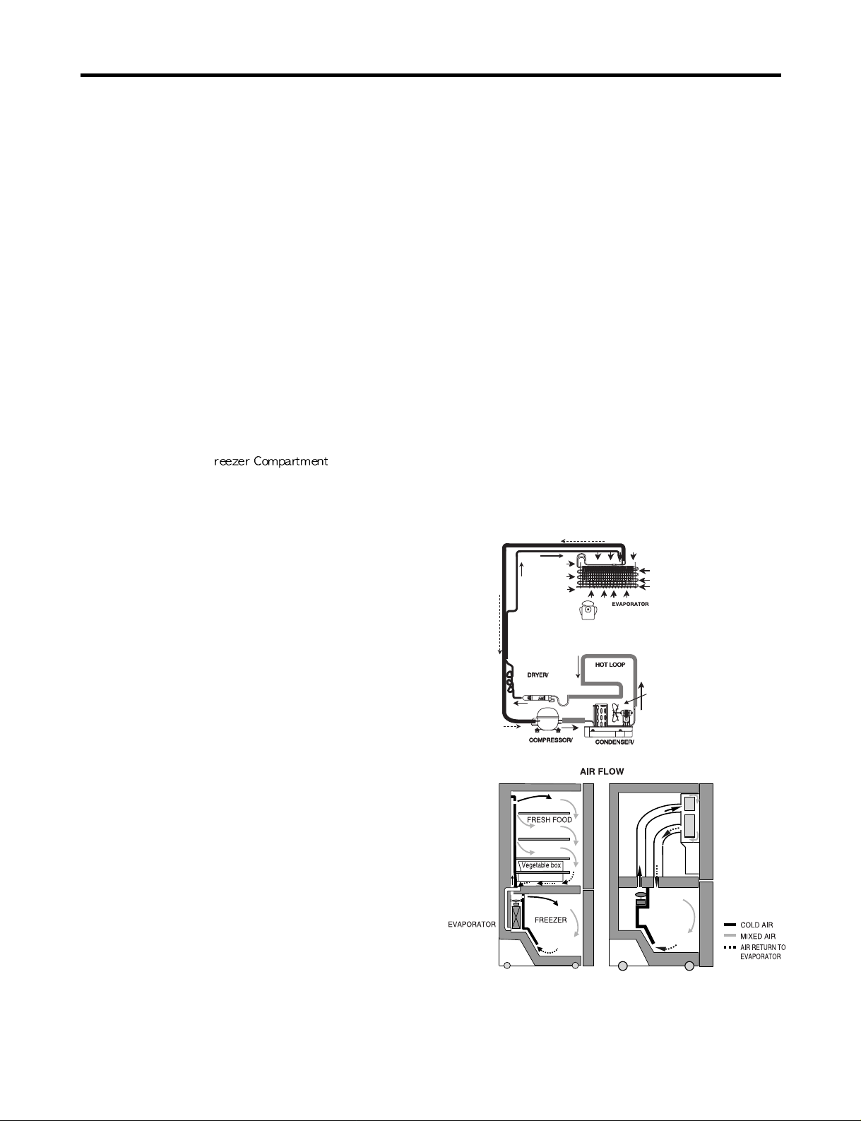
1-5 REFRIGERA TION SYSTEM
Minimum Compressor Capacity Vacuum ............... 21 MIN.
Minimum Equalized Pressure
@ 70°F ....................................................... 49 PSIG
@ 90°F ....................................................... 56 PSIG
Refrigerant R134a .................................................. 5.11 oz.
Compressor ..................................................... 956 BTU/hr
1-6 INSTALLATION
Clearance must be provided at top, sides and rear of the
refrigerator for air circulation.
AT TOP ......................................................................... 2 in
AT SIDES ...................................................................... 1 in
AT REAR ...................................................................... 1 in
1-7 REPLACEMENT PARTS
25 cuft
795.78733.804 795.78743.804
795.78739.804 795.78749.804
Relay..............................................................6748C-0004D
Overload........................................................6750C-0004R
Defrost Thermostat........................................6615JB2005H
Defrost Heater...............................................5300JK1005D
Evaporator Fan Motor....................................4681JB1027C
Capacitor (Running)...................................0CKZZJB2012K
(0CKZZJB2014B)
(0CKZZJB2012H)
Compressor (Hi-Side) TCA31748001
Evaporator (Lo-Side)......................................5421JJ1003B
Condenser....................................................ACG36653801
Dryer..............................................................5851JA2008U
Condenser Fan Motor ...................................4681JB1029D
Temperature Control ...........................ABQ56655301(STS)
ABQ56655303(WB)
Dispenser Control...............................ACQ67140901(STS)
ACQ67140903(WB)
Main Control .................................................EBR41956410
Ice Fan Motor ................................................4681JB1029E
1-8 AIR FLOW / CIRCULATION D’AIR
1. SPECIFICATIONS
- 3 -
EVAPORTOR FAN MOTOR
CONDENSER FAN MOTOR
ICE
ROOM
Glide'N'Serve
- 4 -
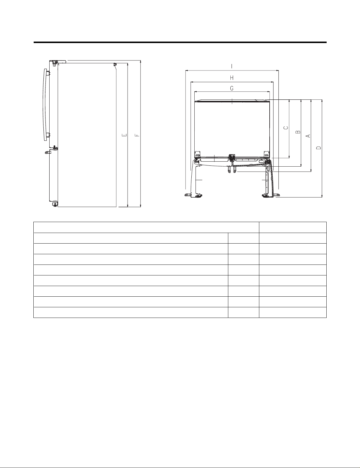
Description 795.787**.803
Depth w/ Handles A 34 1/4 in
Depth w/ Handles B 31 3/4 in
Depth w/ o Door C 27 7/8 in
Depth (Total with Door Open) D 46 1/2 in
Height to Top of Case E 68 3/8 in
Height to Top of Door Hinge F 69 3/4 in
Width G 35 3/4 in
Width (door open 90 deg. w/o handle) H 39 1/4 in
2. PARTS IDENTIFICATION
- 5 -
A
B
G
D
R
F
H
I
K
P
T
Q
C
L
E
M
N
O
A
B
C
D
E
F
G
H
I
K
L
M
N
O
P
Q
R
T
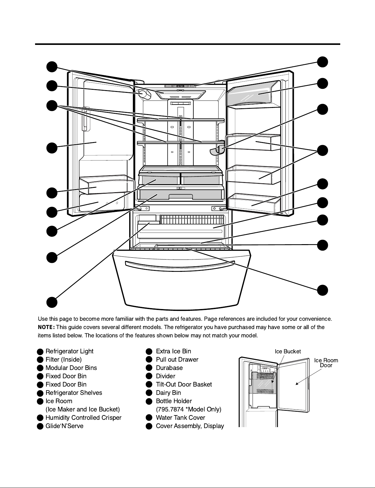
Ice Bucket
Ice Room
Door
Refrigerator Light
Filter (Inside)
Modular Door Bins
Fixed Door Bin
Fixed Door Bin
Refrigerator Shelves
Ice Room
(Ice Maker and Ice Bucket)
Humidity Controlled Crisper
GlideÔNÕServe
Use this page to become more familiar with the parts and features. Page references are included for your convenience.
NOTE:
This guide covers several different models. The refrigerator you have purchased may have some or all of the
items listed below. The locations of the features shown below may not match your model.
Extra Ice Bin
Pull out Drawer
Durabase
Divider
Tilt-Out Door Basket
Dairy Bin
Bottle Holder
(795.7874 *Model Only)
Water Tank Cover
Cover Assembly, Display
3. DISASSEMBLY
- 6 -
3-1 REMOVING AND REPLACING REFRIGERATOR DOORS
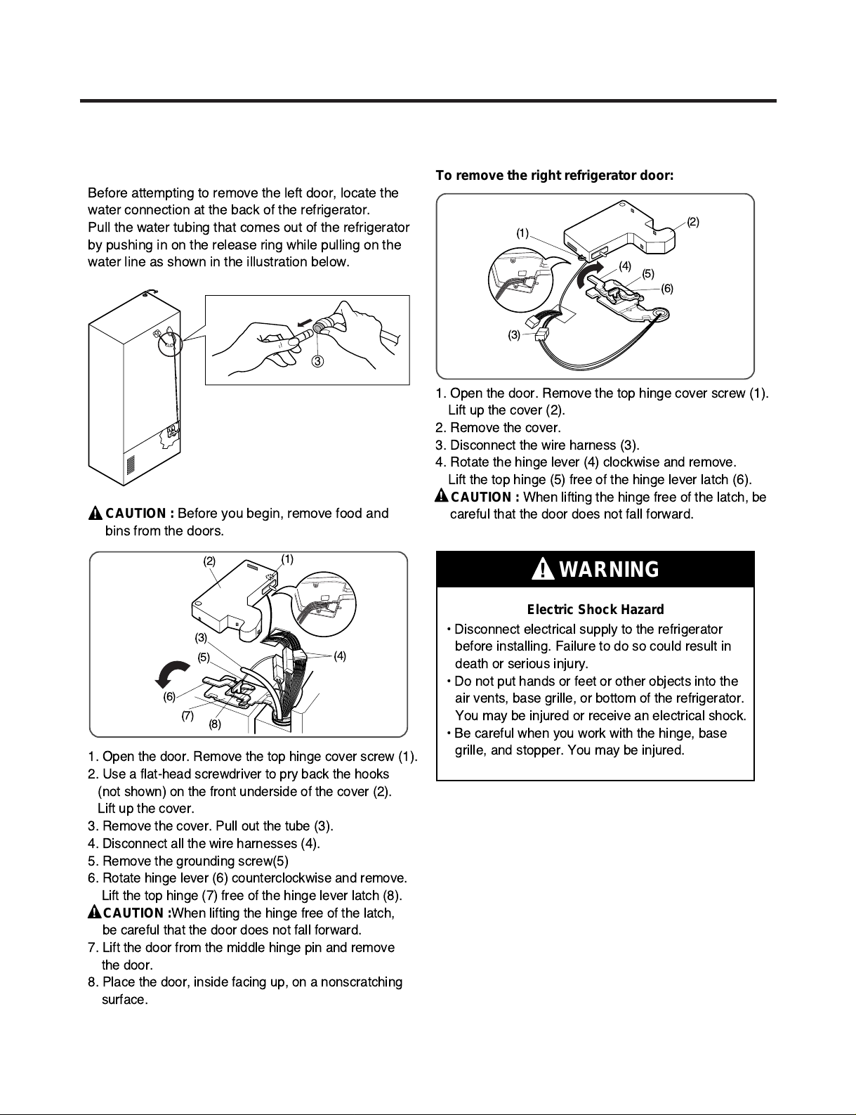
To remove the left refrigerator door:
Before attempting to remove the left door, locate the
water connection at the back of the refrigerator.
Pull the water tubing that comes out of the refrigerator
by pushing in on the release ring while pulling on the
water line as shown in the illustration below.
To remove the right refrigerator door:
1. Open the door. Remove the top hinge cover screw (1).
Lift up the cover (2).
2. Remove the cover.
3. Disconnect the wire harness (3).
4. Rotate the hinge lever (4) clockwise and remove.
Lift the top hinge (5) free of the hinge lever latch (6).
CAUTION : When lifting the hinge free of the latch, be
careful that the door does not fall forward.
Electric Shock Hazard
WARNING
¥ Disconnect electrical supply to the refrigerator
before installing. Failure to do so could result in
death or serious injury.
¥ Do not put hands or feet or other objects into the
air vents, base grille, or bottom of the refrigerator.
You may be injured or receive an electrical shock.
¥ Be careful when you work with the hinge, base
grille, and stopper. You may be injured.
1. Open the door. Remove the top hinge cover screw (1).
2. Use a flat-head screwdriver to pry back the hooks
(not shown) on the front underside of the cover (2).
Lift up the cover.
3. Remove the cover. Pull out the tube (3).
4. Disconnect all the wire harnesses (4).
5. Remove the grounding screw(5)
6. Rotate hinge lever (6) counterclockwise and remove.
Lift the top hinge (7) free of the hinge lever latch (8).
CAUTION :When lifting the hinge free of the latch,
be careful that the door does not fall forward.
7. Lift the door from the middle hinge pin and remove
the door.
8. Place the door, inside facing up, on a nonscratching
surface.
3
CAUTION :
Before you begin, remove food and
bins from the doors.
(1)
(2)
(4)
(3)
(6)
(7)
(8)
(5)
(1)
(2)
(4)
(5)
(6)
(3)
- 7 -
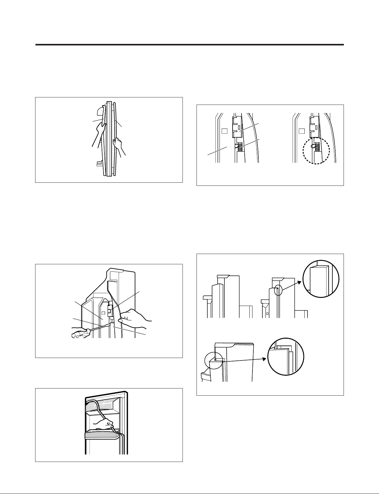
3-2 DOOR
● Door Gasket Removal
1. Remove door frame cover
Starting at top of cover and working down, snap cover
out and away from door.
2. Remove gasket bracket clips
There are two clips on each door. Start bracket removal
near one of the middle clips.
1) Pull gasket back to expose gasket bracket clip and
door frame.
2) Insert a flat tip screwdriver into seam between gasket
bracket and door frame and pry back until clips snap
out.
3) Continue prying back along seam until all clips snap
out.
3. Remove gasket
Pull gasket free from gasket channel on the three
remaining sides of door.
● Door Gasket Replacement
1. Insert gasket bracket clips
1) Insert gasket bracket edge beneath door frame edge.
2) Turn upper gasket bracket spring so that the spring
ends are in the door channel.
3) Push in clip until you hear it snap securely into place.
4) Push in remaining clip until you hear it snap securely
into place.
Note: Make sure that no part of gasket bracket edge
protrudes from beneath door frame edge.
2. Insert gasket into channel
1) Snap gasket assembly into the door bracket.
<Inserting the Gasket Assembly into the Bracket Door>
Frame Cover
Handle
Figure 1
Figure 2
Figure 3
Door
Frame
Gasket
Bracket Clip
Spring
IncorrectCorrect
Figure 4
Figure 5
Gasket
Door
Bracket Clip
Frame
Flat Tip
Screwdriver
Gasket
Bracket
Correct
Incorrect
- 8 -
2) Press gasket into channels on the three remaining
sides of door.
3. Replace door frame cover
Starting at top of cover and working down, snap cover
back into door.
.
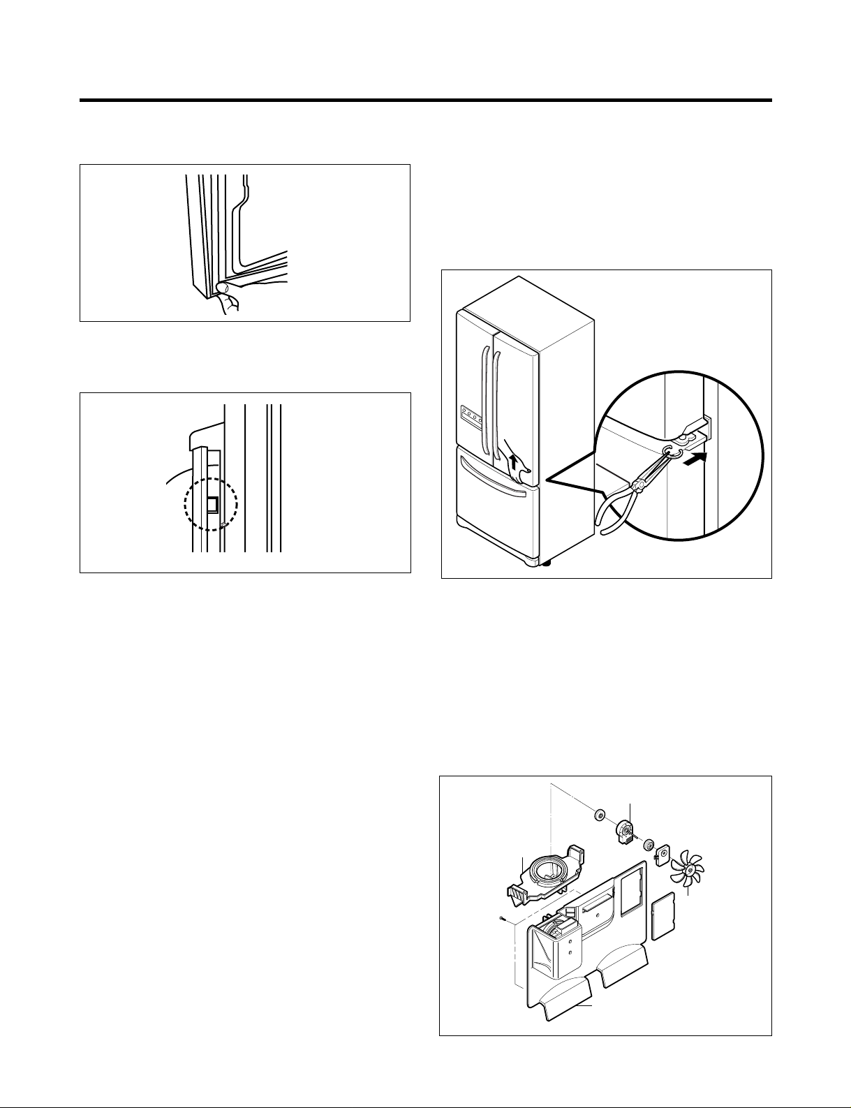
3-3 DOOR ALIGNMENT
If the space between your doors is uneven, follow the
instructions below to align the doors:
1. With one hand, lift up the door you want to raise at
middle hinge.
2. With other hand, use pliers to insert snap ring as shown.
3. Insert additional snap rings until the doors are aligned.
(Three snap rings are provided with unit.)
3-4 FAN AND FAN MOTOR(EVAPORATOR)
1. Remove the freezer shelf. (If your refrigerator has an
icemaker, remove the icemaker first)
2. Remove the plastic guide for slides on left side by
unscrewing phillips head screws.
3. Remove the grille by removing one screw and pulling the
grille forward.
4. Remove the Fan Motor assembly by loosening 2 screws
and disassembling the shroud.
5. Pull out the fan and separate the Fan Motor and Bracket.
Figure 6
Figure 8
Figure 7
GRILLE
FAN MOTOR
FAN
BRACKET
MOTOR
Figure 9
- 9 -
* Ice Fan Scroll Assembly Replacement
1) Remove the plastic guide for slides on left side by
unscrewing phillips head screws.
2) Pull the grille forward as shown in the second picture.
3) Disconnect wire harness of the grille
4) Remove the scroll assembly by loosening 2 screws
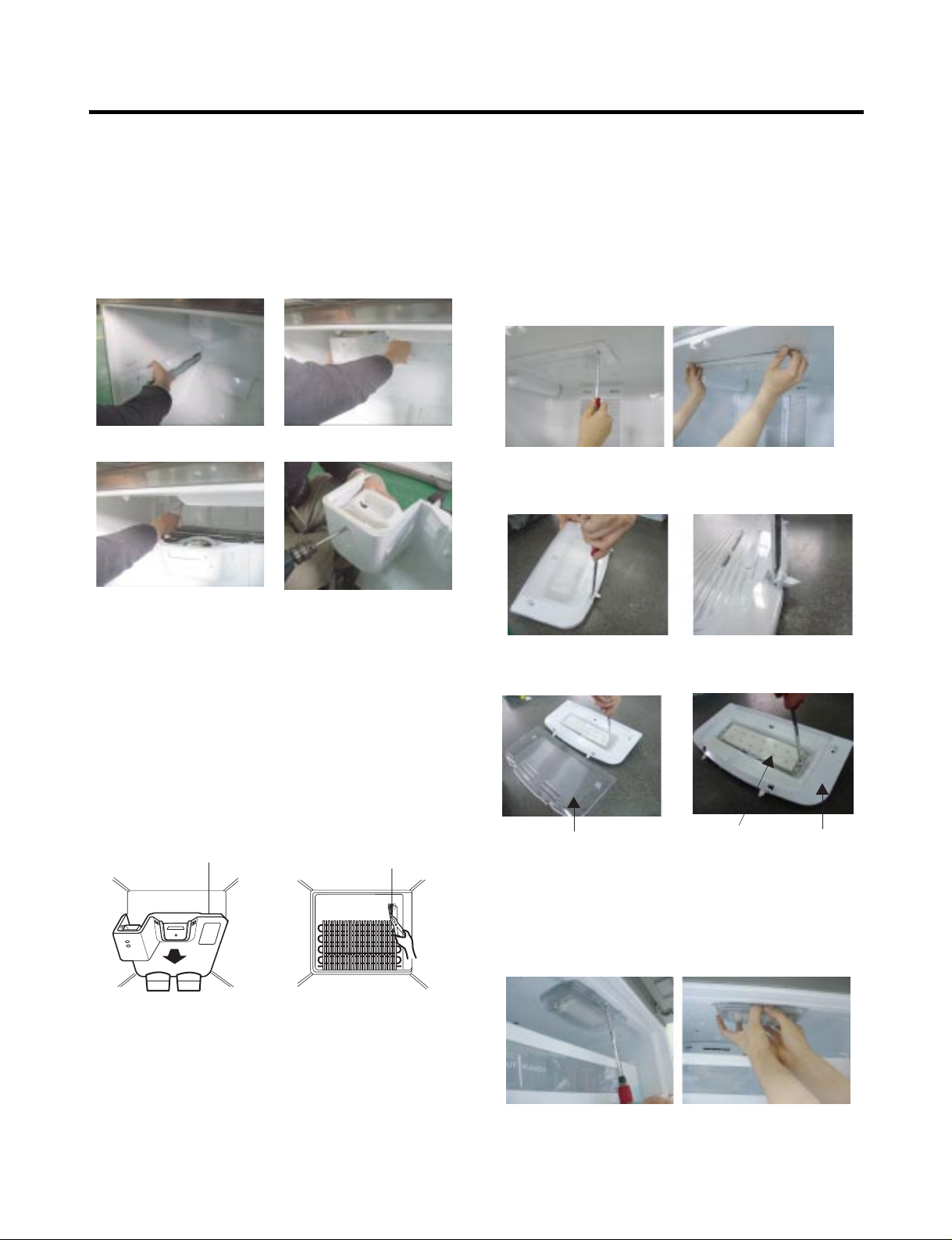
3-5 DEFROST CONTROL ASSEMBLY
Defrost Control assembly consists of Defrost Sensor and
FUSE–M.
The Defrost Sensor works to defrost automatically. It is
attached to the metal side of the Evaporator and senses its
temperature. At 72°C, it turns the Defrost Heater off.
Fuse-M is a safety device for preventing over-heating of
the Heater when defrosting.
1. Pull out the grille assembly. (Figure 10)
2. Separate the connector with the Defrost Control
assembly and replace the Defrost Control assembly
after cutting the Tie Wrap. (Figure 11)
3-6 LAMP
Unplug Refrigerator, or disconnect power at the circuit
breaker.
If necessary, remove top shelf or shelves.
3-6-1 Refrigerator Compartment Lamp
1) Release 2 screws.
2) Hold both ends with your both hands and pull it
downward to remove it.
3) Use a flat tool as shown below to remove the cover
lamp.
4) As shown below, use a flat tool to remove
the cover lamp.
3-6-2 Freezer Compartment Lamp
1. Unplug refrigerator power cord form outlet.
2. Remove screw with direver.
3. Grasp the cover Lamp,pull the cover downward.
GRILLE ASSEMBLY
Figure 10
DEFROST-CONTROL
ASSEMBLY
Figure 11
Figure 12
Figure 13
Cover, Lamp
Case Lamp
LED, Assembly
Figure 14
Figure 15
(1) (2)
(3) (4)
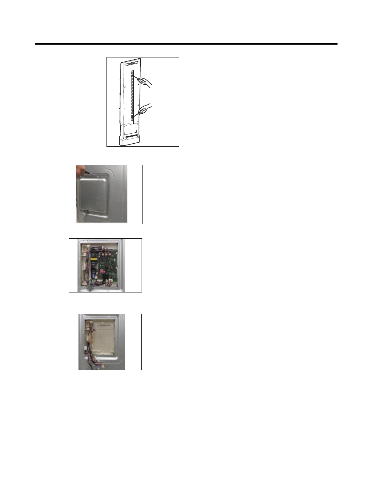
3-7 MULTI DUCT
1. Remove the upper and
lower Caps by using a flat
screwdriver, and remove
2 screws. (Figure 17)
2. Disconnect the lead wire
on the bottom position.
3-8 MAIN PWB
1) Loosen the 4 screws on the PWB cover.
2) Remove the PWB cover
3) Disconnect wire harness and replace the main PWB in
the reverse order of removal.
Figure 16
- 10 -
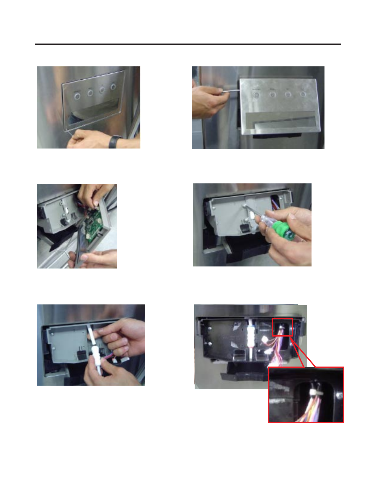
3-9 SERVICEABILITY REVIEW FOR HIDDEN DISPENSER
- 11 -
1) With the unit unlugged from the power source,
you can manually open the dispenser cover using
a small flat blade screwdriver. The cover will remain
opened during the repair.
2) Unscrew left and right side (cross driver)
3)All harness have to be removed before
separation of cover
4) Unscrew 2 points and then remove connecter-cover
5) Separate tube (5/16") from connecter
(clip have to be removed first)
6) Cut the wire fixing the
harness at the rib on the
upper rib of the cass
assembly harness outlet.
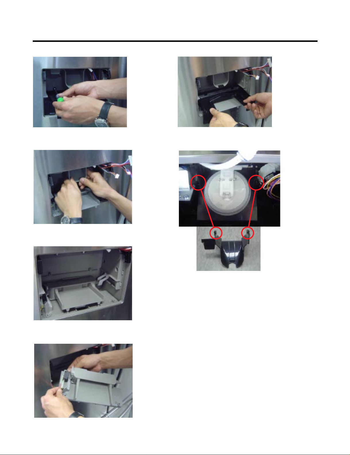
- 12 -
9) Pull down funnel .
10) Fix the left rib and the right rib at the marked
spots correctly.
11) Before separation of Bracket, connecting
rod have to be at back side position.
12) Separate the Switch connection harness.
7) Unscrew 2 points to separate
tray-cover
8) Separate the Tray-cover after pull them
toward your body.
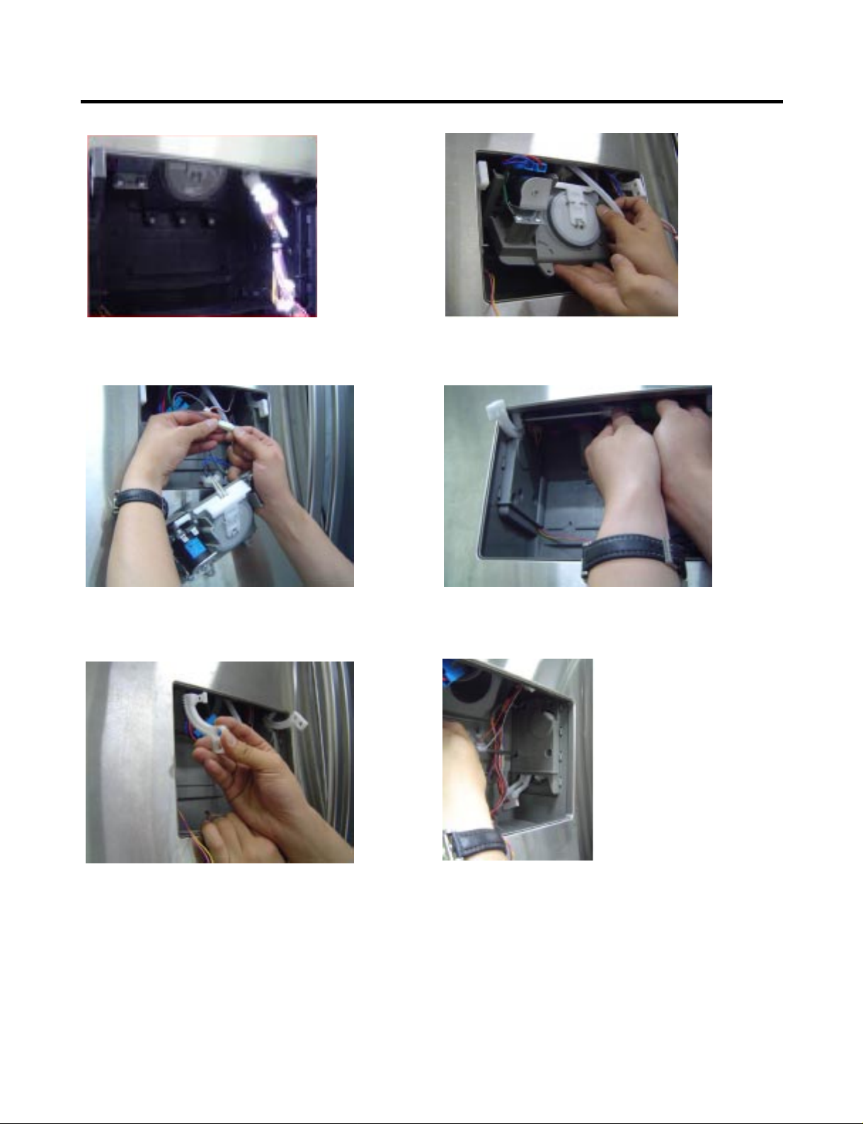
- 13 -
15) All harness have to be separated. 16) Unscrew the 1 screw at the gear ( left and right)
17) Separate gear ( left and right) 18) Unscrew 2 point with short length driver
13) Unscrew 3 points at the Duct Assembly. 14) Pull down and rotate toward your body
duct assembly for separation.
- 14 -
19) Pull motor box inside and then
separate harness.
20) Sensor box can be disassembled
after removal of 3 screws in same case of motor box.
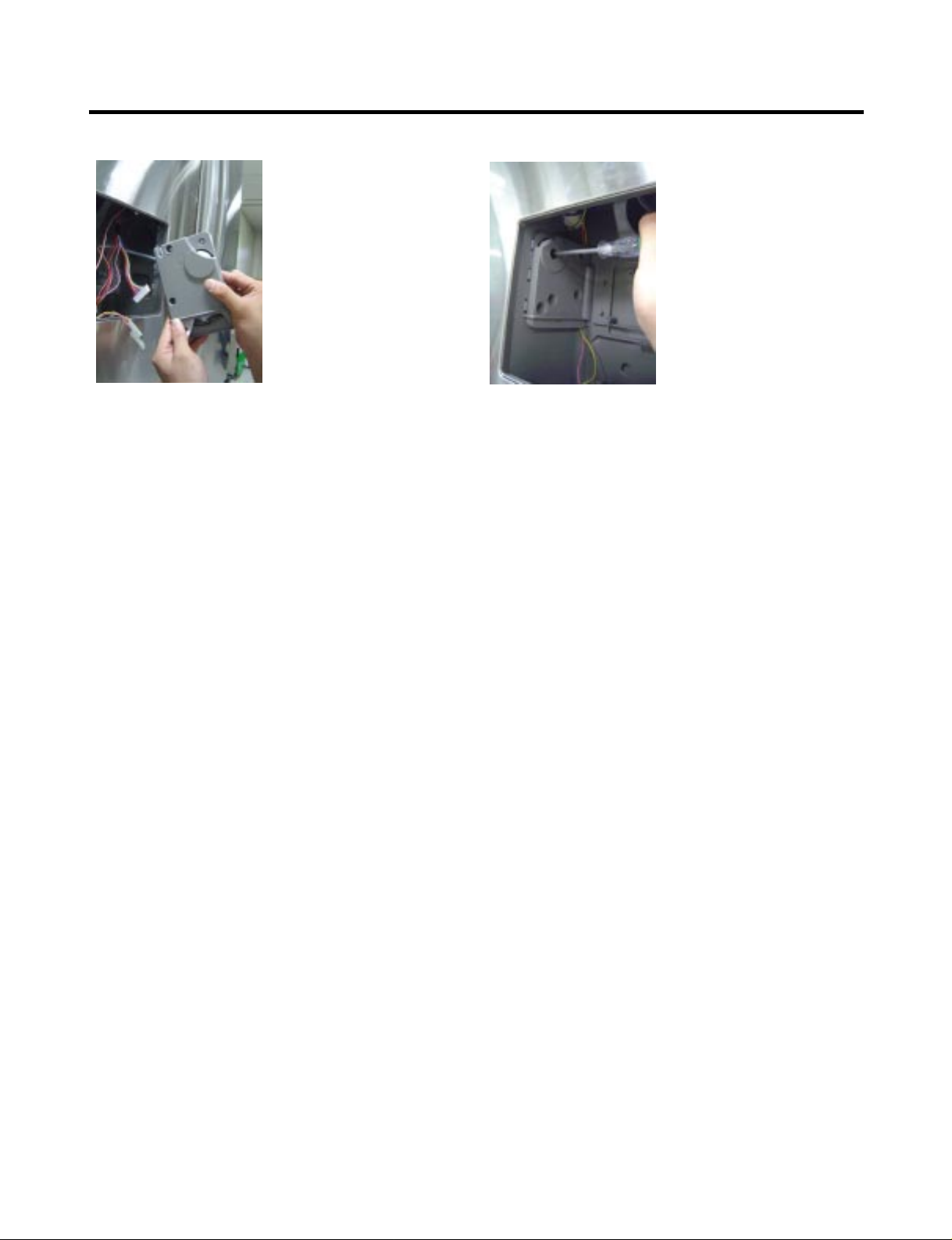
3-10 ICE CORNER DOOR REPLACEMENT
1) Loosen the front screw as shown in the picture.
2) Lift up the hinge with one hand.
3) Pull out the Ice Corner Door with the other hand.
3-11 ICEMAKER ASSEMBLY
1) Loosen two screws as shown in the first picture.
2) Disconnect the wire harness & ground screw replace
theIcemaker assembly in the reverse order of removal.
3) It separates a ground connection screw.
- 15 -
hinge
3-12 AUGER MOTOR COVER
1) After removing the icemaker remove the (5) stainless
screws holding the auger motor cover, shown in the
picutres below.
2) Grip the bottom of motor cover assembly and pull out it.
3) Disconnect wire harness of motor cover assembly.
There is a auger motor on the back, as shown in the
picture.
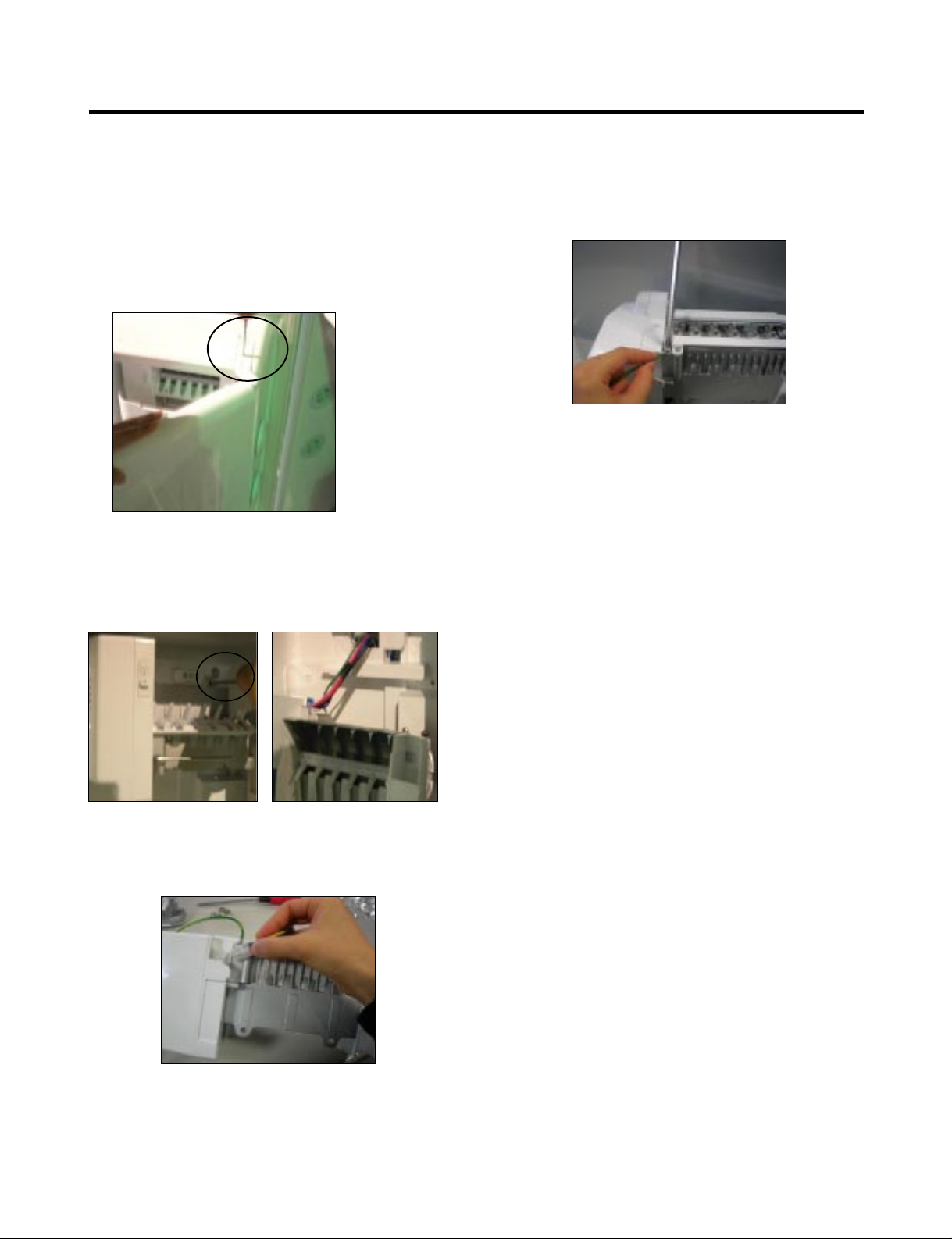
3-13 HOW TO REMOVE THE SUB PCB
1) Lift up the Fixed Door Bin to remove.
2) Unscrew one screw fixing the Cover Front and
the Sub PCB.
3) Pull the Cover Front to remove.
4) Insert the (-) screw driver into the center hole of the
| upper Sub PBC, and remove the Sub PCB.
5) Revove two housings connecting to the Sub PCB.
6) Pull the Sub PCB to remove.
- 16 -
Auger Motor
3-14 HOW TO REMOVE A DOOR ICE BIN
1) Grip the handles, as shown in the picture.
2) Lift the lower part slightly.
3) Take the Ice Bin out slowly.
3-15 HOW TO INSERT A DOOR ICE BIN
1) Insert the Ice Bin, slightly tilting it to avoid touching the
Icemaker. (especially, ice maker lever)
Insert the ice bucket carefully avoid contacing the
automatic shut off arm.
- 17 -
1
2
- 18 -
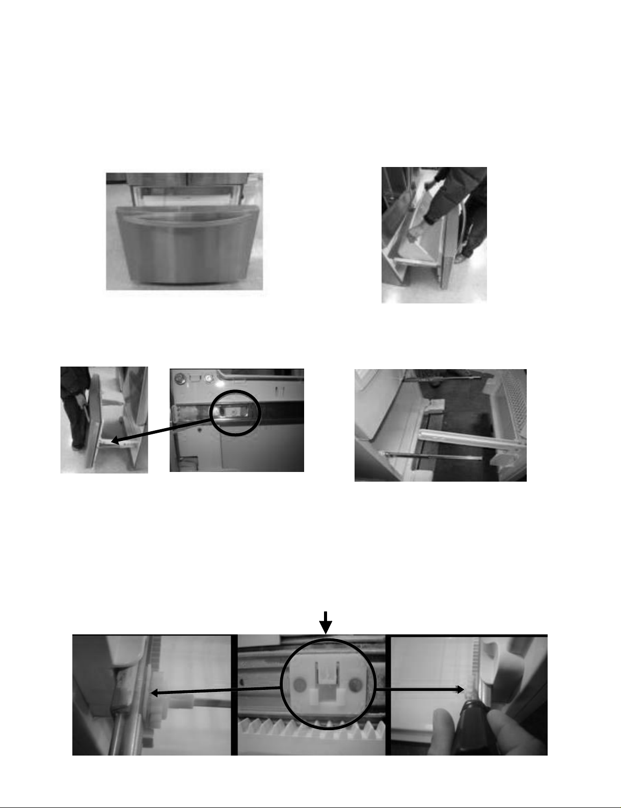
3-16 HOW TO REMOVE AND REINSTALL THE PULLOUT DRAWER
3-16-1 Follow Steps to Remove
Step 1) Open the freezer door.
Step 3) Remove the two screws from the guide rails (one
from each side).
Step 2) Remove the lower basket.
Step 4) Lift the freezer door up to unhook it from the rail
support and remove.
Pull both rails to full extension.
Step 5) First: Remove the gear from the left side first by releasing the tab behind the gear, place a screwdriver between the
gear and the tab and pull up on the gear.
Second: Remove the center rail.
Third: Remove the gear from the right side by following the same steps for the left side.
NOTE: THIS TAB MUST BE PUSHED IN TO RELEASE THE GEAR.
- 19 -
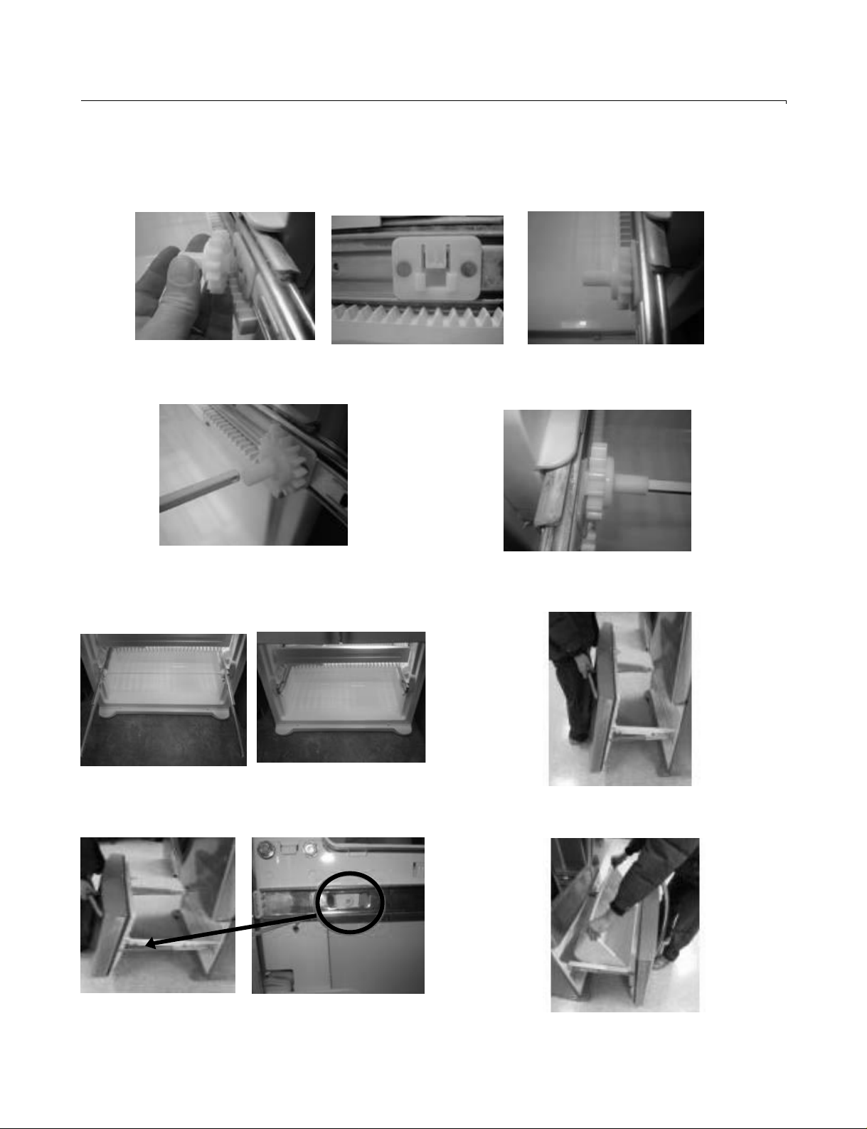
3-16-2 Follow Steps to Reinstall
Step 1) Reinstall the right side gear into the clip.
Step 2) Insert the rail into the right side gear. Gears do not
need to be perpendicular to each other.
Step 4) The rail system will align itself by pushing the rails
all the way into the freezer section.
Pull the rails back out to full extension.
Step 6) Reinstall the two screws into the guide rails
(one from each side).
Step 3) Insert the rail into the left side gear, and insert the
gear into the clip.
Step 5) Reinstall the freezer door by inserting the rail tabs
into the guide rail.
Step 7) Reinstall the lower basket, and close the freezer
door.
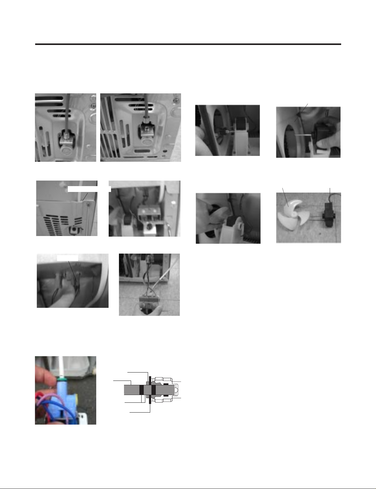
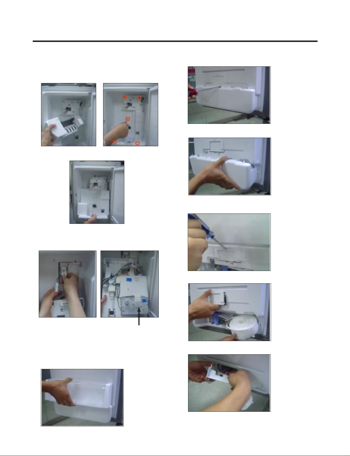
3-17. WATER VALVE DISASSEMBLY METHOD
1) Turn off the water. Then separate the water line from the
valve.
2). Separate the Mechanical Cover and Valve Screw.
3) Separate the housing and pull out the valve.
4) Lay a dry towel on the floor and get ready to spill water
from the water filter. Pull out the Cilp. Then press te
collet to separate the tube from the connector and pour
out the water until emptied.
3-18. FAN AND FAN MOTOR DISASSEMBLY
METHOD
1) Using a short screwdriver, loosen one SCREW in
DRAIN PIPE ASSEMBLY and one connected to the
MOTOR COVER.
2) Pull and separate the FAN ASSEMBLY and MOTOR
turning counterclockwise based on the MOTOR SHAFT.
The assembly is in the reverse order of the disassembly
and take special care for the following details.
1. Be careful not to bend the tube during assembly.
2. Press the WATER DISPENSER button until water pours
out and check for leakage in the CONNECTOR TUBE (It
differs by the water pressure but usually takes about 2
minutes until water pours out.)
Collet
Tube
Insert Line
Clip
Mechanical Cover
Housing
→
→
MOTOR COVER
FAN ASSEMBLY MOTOR
- 20 -
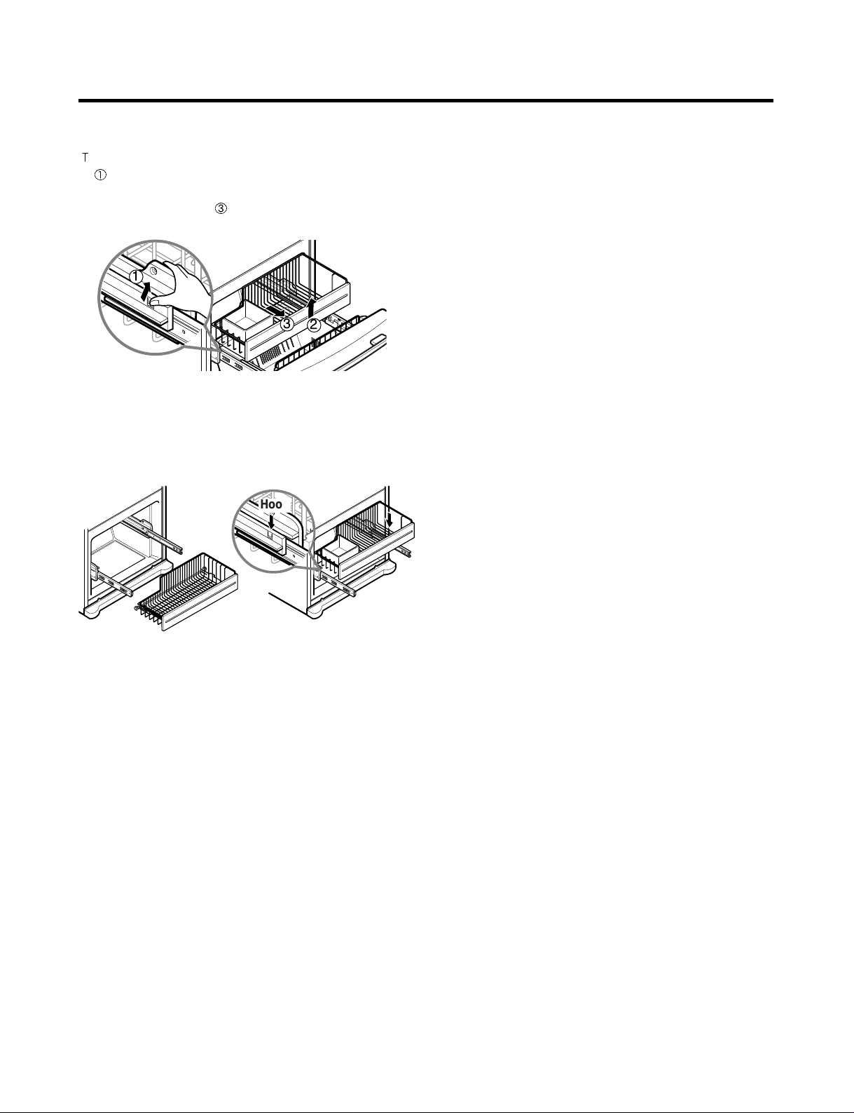
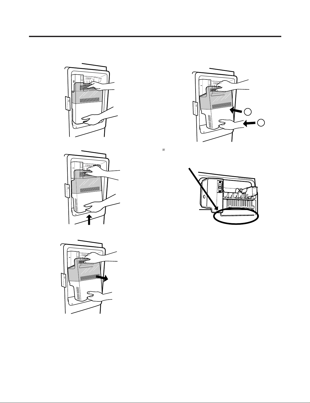
3-19 PULL OUT DRAWER
o separate the drawer, push the front left and right hooks
in
direction to pull up and remove.
Then gently lift the gear part of rear left and right side of the
drawer and pull it out in
direction.
To install, reposition the gear part of rear left and right side
of the drawer after pulling out both rails as much as possible,
and gently push down both left and right side while checking
the hook on the front part.
- 21 -
2
3
1
Hook
4-1 COMPRESSOR
4-1-1 Role
The compressor intakes low temperature and low pressure
gas from the evaporator of the refrigerator and compresses
this gas to high-temperature and high-pressure gas. It then
delivers the gas to the condenser.
4-1-2 Composition
The compressor includes overload protection. The PTC
starter and OLP (overload protector) are attached to the
outside of the compressor. Since the compressor is
manufactured to tolerances of 1 micron and is hermetically
sealed in a dust and moisture-free environment, use
extreme caution when performing repairs.
4-1-3 Note for Usage
(1) Be careful not to allow over-voltage and over-current.
(2) If compressor is dropped or handled carelessly, poor
operation and noise may result.
(3) Use proper electric components appropriate to the
Particular Compressor in your product.
(4) Keep Compressor dry.
If the Compressor gets wet (in the rain or a damp
environment) and rust forms in the pin of the Hermetic
Terminal, poor operation and contact may result.
(5) When replacing the Compressor, be careful that dust,
humidity, and soldering flux don’t contaminate the inside
of the compressor. Dust, humidity, and solder flux
contaminate the cylinder and may cause noise,
improper operation or even cause it to lock up.
4-2 PTC-STARTER
4-2-1 Composition of PTC-Starter
(1) PTC (Positive Temperature Coefficient) is a no-contact
semiconductor starting device which uses ceramic
material consisting of BaTiO
3.
(2) The higher the temperature is, the higher the resistance
value. These features are used as a starting device for
the Motor.
4-2-2 Role of PTC-Starter
(1) The PTC is attached to the Sealed Compressor and is
used for starting the Compressor Motor.
(2) The compressor is a single-phase induction motor.
The starting operation, the PTC allows current flow to
both the start winding and main winding.
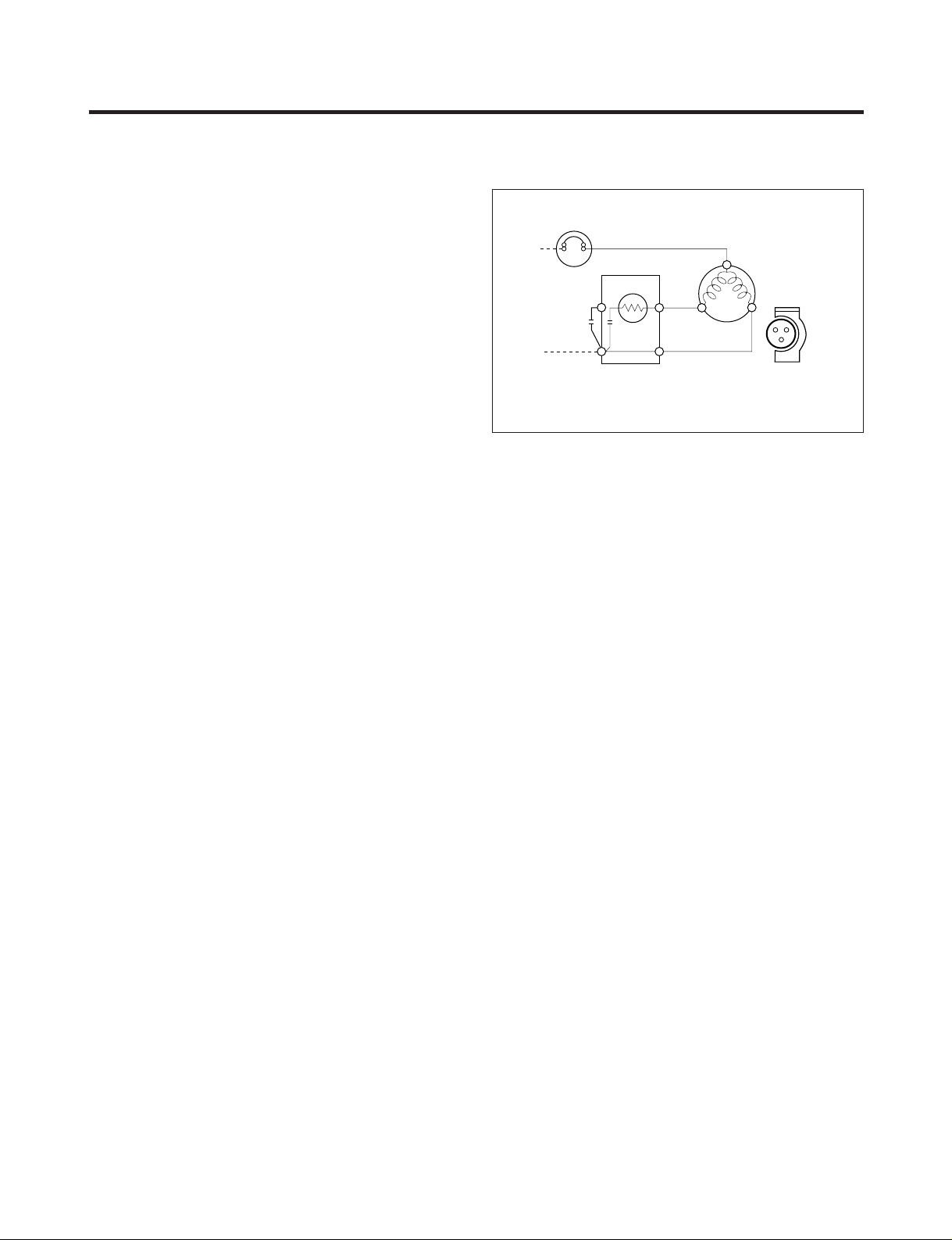
4-2-3 PTC-Applied Circuit Diagram
● Starting Method for the Motor
4-2-4 Motor Restarting and PTC Cooling
(1) It requires approximately 5 minutes for the pressure to
equalize before the compressor can restart.
(2) The PTC device generates heat during operation.
Therefore, it must be allowed to cool before the
compressor can restart.
4-2-5 Relation of PTC-Starter and OLP
(1) If the compressor attempts to restart before the PTC
device is cooled, the PTC device will allow current to
flow only to the main winding.
(2) The OLP will open because of the over current
condition. This same process will continue (3 to 5
times) when the compressor attempts to restart until
the PTC device has cooled. The correct OLP must be
properly attached to prevent damage to the
compressor.
Parts may appear physically identical but could have
different electrical ratings. Replace parts by part
number and model number. Use only approved
substitute parts.
4-2-6 Note for Using the PTC-Starter
(1) Be careful not to allow over-voltage and over-current.
(2) Do not drop or handle carelessly.
(3) Keep away from any liquid.
If liquid such as oil or water enters the PTC,
PTC materials may fail due to breakdown of their
insulating capabilities.
(4) If the exterior of the PTC is damaged, the resistance
value may be altered. This can cause damage to the
compressor and result in a no-start or hard-to-start
condition.
(5) Always use the PTC designed for the compressor and
make sure it is properly attached to the compressor.
Parts may appear physically identical but could have
different electrical ratings. Replace parts by part
number and model number. Use only approved
substitute parts.
PTC STARTER
SEALED
TERMINAL
COMPRESSOR
MOTOR
C
M
S
M
3
6
5
S
N
L1
OVERLOAD PROTECTOR
Resistance Starter Capacitor Running
PTC
22
4. ADJUSTMENT
- 22 -
4-3 OLP (OVERLOAD PROTECTOR)
4-5-1 Definition of OLP
(1) OLP (OVERLOAD PROTECTOR) is attached to the
Compressor and protects the Motor by opening the
circuit to the Motor if the temperature rises and
activating the bimetal spring in the OLP.
(2) When high current flows to the Compressor motor, the
Bimetal works by heating the heater inside the OLP,
and the OLP protects the Motor by cutting off the
current flowing to the Compressor Motor.
4-5-2 Role of the OLP
(1) The OLP is attached to the Sealed Compressor used
for the Refrigerator. It prevents the Motor Coil from
being started in the Compressor.
(2) For normal operation of the OLP, do not turn the Adjust
Screw of the OLP in any way.
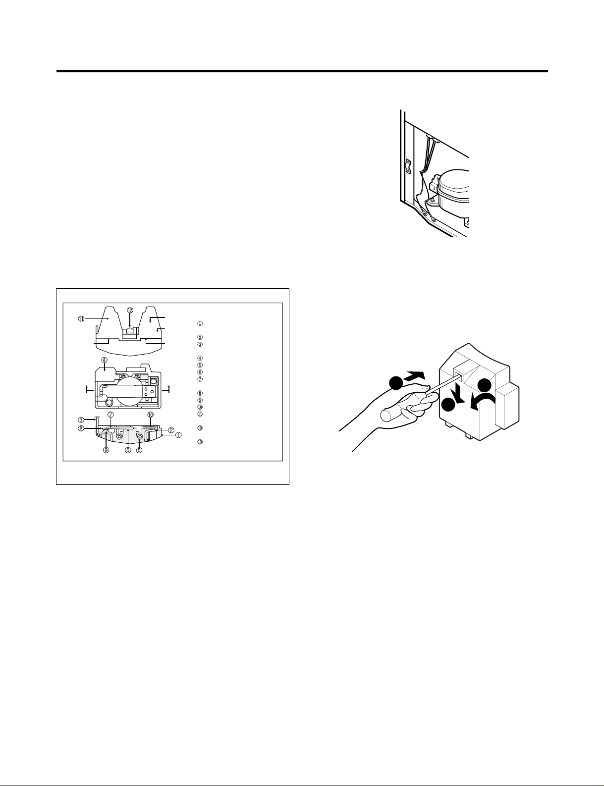
4-4 TO REMOVE THE COVER PTC
(1) Remove the Cover Back M/C.
(2) Disconnect two housing upper side of comp connected
in.
(3) Loosen two screws on comp base.
(4) Use a L-shaped flap tool to pry off the cover.
(5) Assembly in reverse order of disassembly.
Part
Customer part
number
Lot code/
date code
330 FBYY -S1 BOX98
12345678
Physical
termination
part number
Electrical
characteristics
part number
No. Name
Base, phenolic
(UL 94 V-0 rated)
Movable arm support, plated steel
Stationary contact support,
plated steel
Heater support, plated steel
Heater, resistance alloy
Disc, thermostatic alloy
Movable arm, spring temper
copper alloy
Contact, movable, silver on copper
Contact, stationary, silver on copper
Slug, plated steel
Cover, polyester
(UL 94 V -0 rated)
Pin connector, plated copper alloy
(To engage 2.33/2.66 mm dia. pin)
Quick-connect terminal, brass,
conforms to UL 310, MEMA
DC-2, DIN 46344
(OVERLOAD PROTECTOR cross section)
Figure 19
2
3
1
- 23 -
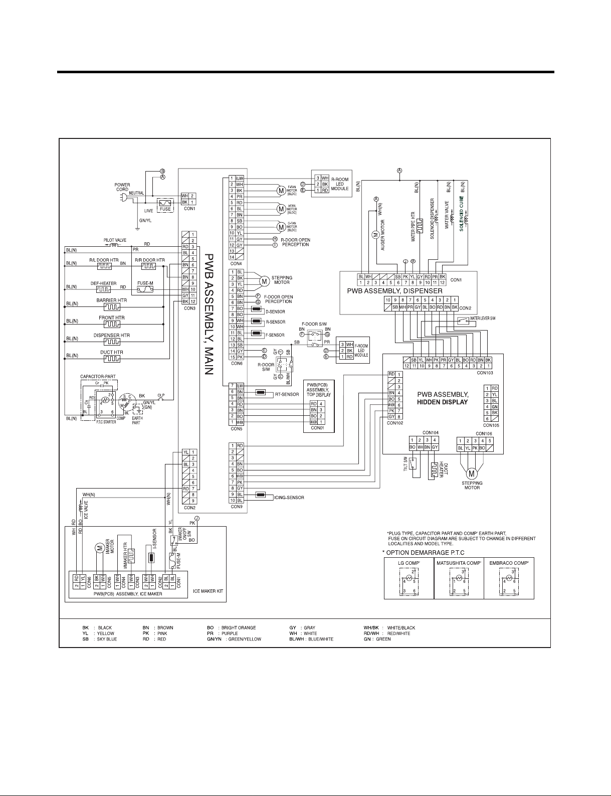
5. CIRCUIT DIAGRAM
- 24 -
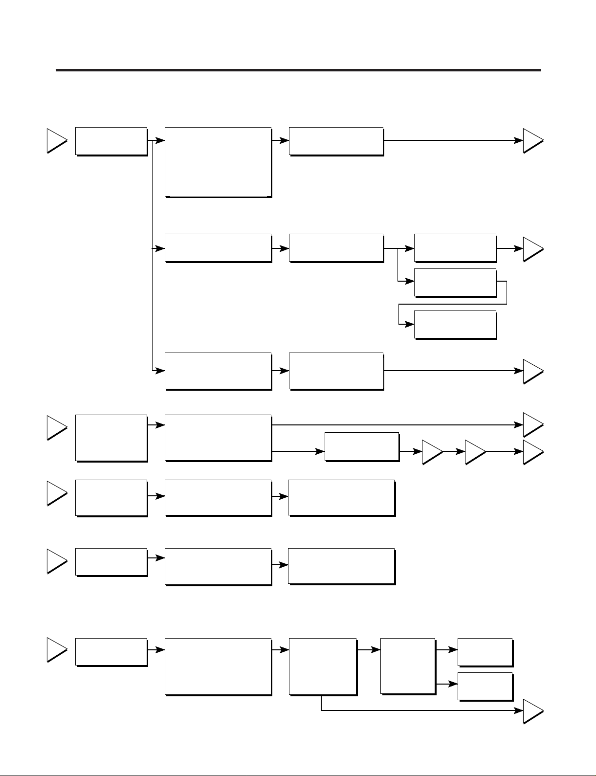
6. TROUBLESHOOTING
- 25 -
6-1 COMPRESSOR AND ELECTRIC COMPONENTS
1
2
3
4
5
2
5
5
3
5
1
43
YES
NO
YES
The range of resistance is between 1~50Ω(ok)
Open or short
YES YES
NO
NO
Power Source.
No Voltage.
(Rated Voltage
±10%)?
Replace OLP.
Reconnect.
Reference Page12.
Reference Page12.
Did
compressor
start?
Compressor
is OK
Replace the
compressor
Check connection
condition.
OLP disconnected?
Advise customer that
power supply needs to be
checked by an electrician.
Replace
Compressor.
Supply
voltage rating
with ±10%.
Applied voltage isn't
in acceptable range.
(115V ±10%)
Remove PTC-Starter
from Compressor and
measure voltage
between Terminal C of
Compressor and
Terminal 5 or 6 of PTC.
Check resistance
between M-C, S-C and
M-S in Motor
Compressor.
Check resistance of
two terminals in
PTC-Starter.
Check resistance of two
terminals in OLP.
Check the power supply
under load.
(Compressor attempting
to re-start after being off
for 5 minutes).
Check
resistance of
Motor
Compressor.
Check
resistance of
PTC-Starter.
Check OLP.
Check
starting state.
 Loading...