

Kenmore 795.76083.600, 795.76084.600, 795.76093.600, 795.76824.600, 795.76282.600 Service Manual
...
R
BOTTOM FREEZER REFRIGERATOR
Use & Care Guide
REFRIGERATOR
SERVICE MANUAL
CAUTION
BEFORE SERVICING THE PRODUCT
READ THE SAFETY PRECAUTIONS IN THIS MANUAL.
MODELS:
795.76082.600
795.76084.600
795.76089.600
795.76092.600
795.76083.600
795.76093.600
795.76282.600
795.76824.600
795.76289.600
795.76292.600
795.76283.600
795.76293.600
Sears, Roebuck and Co., Hoffman Estates, IL 60179 U.S.A.
www.sears.com

CONTENTS
SAFETY PRECAUTIONS ..........................................................................................................
1. SPECIFICATIONS ..................................................................................................................
2. PARTS IDENTIFICATION .......................................................................................................
3. DISASSEMBLY ......................................................................................................................
3.1 Door ..................................................................................................................................
3.2 Door switch ........................................................................................................................
3.3 Fan and fan motor ..............................................................................................................
3.4 Defrost control assembly ...................................................................................................
3.5 Lamp .................................................................................................................................
3.6 Refrigerator control box .....................................................................................................
3.7 Multi duct ...........................................................................................................................
3.8 How to remove and reinstall the pullout drawer ...................................................................
3.9 Cover Valve .......................................................................................................................
4. ADJUSTMENT ......................................................................................................................
4.1 Compressor ......................................................................................................................
4.2 PTC-Starter .......................................................................................................................
4.3 OLP (overload protector) ...................................................................................................
4.4 To remove the cover PTC ...................................................................................................
5. CIRCUIT DIAGRAM ...............................................................................................................
6. TROUBLESHOOTING ...........................................................................................................
6.1 Compressor and electrical components .............................................................................
6.2 PTC and OLP .....................................................................................................................
.
6.3 Other electrical components ..............................................................................................
6.4 Service diagnosis chart ......................................................................................................
6.5 Refrigeration cycle .............................................................................................................
7. ICEMAKER OPERATING PRINCIPLES AND REPAIR ..........................................................
7.1 Operation Principle ............................................................................................................
.
7.2 Ice maker functions ............................................................................................................
7.3 Defect diagnosis function ...................................................................................................
8. DESCRIPTION OF FUNCTION & CIRCUIT OF MICOM .........................................................
8.1 Function ............................................................................................................................
8.2 PCB function .....................................................................................................................
8.3 Resistance specification of sensor .....................................................................................
8.4 Troubleshooting ................................................................................................................
8.5 Main PWB assembly and parts list .....................................................................................
8.6 PWB diagram ....................................................................................................................
9. EXPLODED VIEW AND REPLACEMENT PART LIST ...........................................................
2
3
5
6
6
6
7
7
7
7
7
8
11
12
12
12
13
13
14
15
15
16
17
18
19
21
21
22
24
25
25
29
37
38
40
43
45
SAFETY PRECAUTIONS
Please read thefollowing instructions before servicing your
refrigerator.
1. Check the refrigerator for current leakage.
2. To prevent electric shock, unplug before servicing.
3. Always check line voltage and amperage.
4. Use standard electrical components.
5. Don't touch metal products in the freezer with wet
hands. This may cause frostbite.
6. Prevent water from spiling onto electric elements or the
machine parts.
7. Before tilting the refrigerator, remove all materials from
on or in the refrigerator.
8. When servicing the evaporator, wear gloves to prevent
injuries from the sharp evaporator fins.
9. Service on the refrigerator should be performed by a
qualified technician. Sealed system repair must be
performed by a CFC certified technician.
- 2 -

1. SPECIFICATIONS
1-1 DISCONNECT POWERC ORDB EFORE SERVICING IMPORTANT
RECONNECTALL GROUNDING DEVICES.
All parts of this appliance capable of conducting electrical current are grounded. If grounding wires, screws, straps, clips, nuts or washers
used to complete a path to ground are removed for service, they must be returned to their original position and properly fastened.
1-2 IMPORTANT NOTICE
This information is intended for use by individuals possessing adequate backgrounds of electrical, electronic and mechanical experience.
Any attempt to repair a major appliance may result in personal injury and property damage. The manufacturer or seller cannot be
responsible for the interpretation of this information, nor can it assume any liability in connection with its use.
ELECTRICAL SPECIFICATIONS
1.3
Temperature Control (Position: MID) ............................................................................................................................................. -6°F to +8°F
Defrost Control ...................................................................................................................................................................................Automatic
Defrost Thermostat .....................................................................................................................................................................................50°F
Electrical Rating : 115VAC, 60Hz...............................................................................................................................................................1- 5 A
Maximum Current Leakage .....................................................................................................................................................................0.5mA
Maximum Ground Path Resistance ..................................................................................................................................................0.14 Ohms
Energy Consumption
....................................................................................................................................
20 cu.ft 482kWh/yr(Energy Star)
22 cu.ft 494kWh/yr(Energy Star)
1-4 NO LOADP ERFORMANCE
Control Position: MID/MID
AndAmbient of: 70°F
Fresh Food, °F...............................................................
Frozen Food, °F..............................................................
Percent Running Time........................................................
33°F to 41°F
-4°F to +4°F
25%-35%
1-5 REFRIGERATIONS YSTEM
Minimum Compressor Capacity Vacuum ...................................21 in
Minimum Equalized Pressure
@70°F......................................................................49PSIG
@90°F......................................................................56PSIG
Refrigerant R134a................................................................. 4.2. oz
Compressor ................................................................... 700 BTU/hr
90°F
......................................................................................
......................................................................................
......................................................................................
33°F to 41°F
-4°F to +4°F
.
...
.
45%-60%
1-6 INSTALLATION
Clearance must be provided at top, sides and rear of the refrigerator
for air circulation.
AT TOP..........................................................................................1 in
AT SIDES.................................................................................. 1/8 in
AT REAR.......................................................................................1 in
- 3 -
PERFORMANCE DATA
(NORMAL OPERATING CONDITIONS)
AMB WATTS
70°F
90°F
110°F
98 (+10 / -10)
98 (+10 / -10)
103 (+5 / -5)
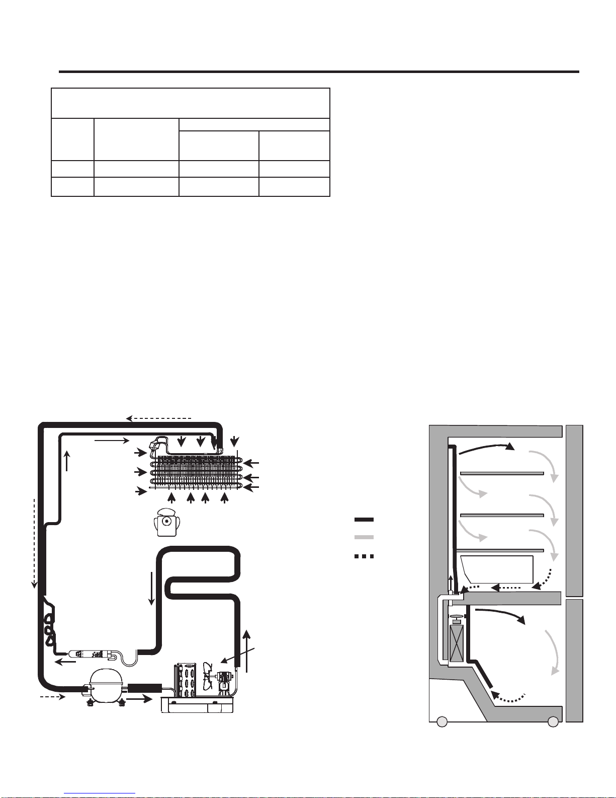
1-8 AIR FLOW / CIRCULATION D’AIR.
SYSTEM PRESSURE (PSIG)
HIGH SIDE LOW SIDE
98 (+5 / -3)
132 (+3 / -3)
180 (+5 / -5)
(-5) to (-2)
(-4) to 1
(-2) to 3
1-7 REPLACEMENT PARTS
Relay........................................
Overload...................................
Defrost Thermostat ..................
Defrost Heater......................
Evaporator Fan Motor...............
Capacitor..................................
Compressor (Hi-Side) ...............
Evaporator (Lo-Side).................
Condenser ................................
Dryer..........................................
Condenser Fan Motor................
Temperature Control
Main Control..............................
..................
(20 cu.ft ) 5300JB1100D
(22 cu.ft ) 5300JB1100J
0CZZJB2003H
6748JJ8002A
6750JJ8002A
6615JB2005C
4680JK1002B
2521JJ8004A
5421JJ1001B
5403JJ1007A
5851JJ2002B
4680JK1001B
6871JB2047A
6871JB1215A
EVAPORATORFAN
DRYER
COMPRESSOR
EVAPORATOR
HOTLOOP
CONDENSER
CONDENSER FAN
- 4 -
COLDAIR
MIXEDAIR
AIR RETURN TO
EVAPORATOR
EVAPORATOR
FRESHFOOD
Vegetablebox
FREEZER
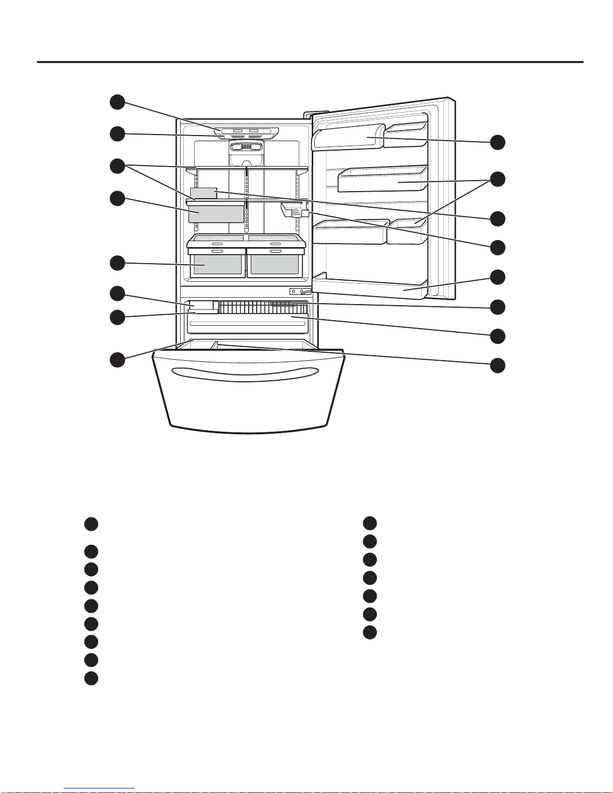
2. PARTS IDENTIFICATIONS
PARTSANDFEATURES
A
B
C
D
E
F
G
H
P
O
N
M
L
K
J
I
Use this section to become more familiar with the parts and features.
NOTE:This guide covers several different models. The refrigerator you have purchased may have some
or all of the items listed below. The locations of the features shown below may not match your model.
J
Cool Sense Electronic Temperature
A
Control System
B
Refrigerator Light
C
Refrigerator Shelves
D
Snack Pan
Supra Fresh Crisper with Tilt-Out Compartment
E
Adjusta Cube Ice Maker
F
G
Ice Bin
H
Durabase
Divider
I
Glide-Out Drawer Basket
Freezer Light
K
Refrigerator Door Rack
L
M
Wine Rack*
N
Egg Box
Modular Door Bins
O
Dairy Corner
P
On some models
*
- 5 -
3. DISASSEMBLY
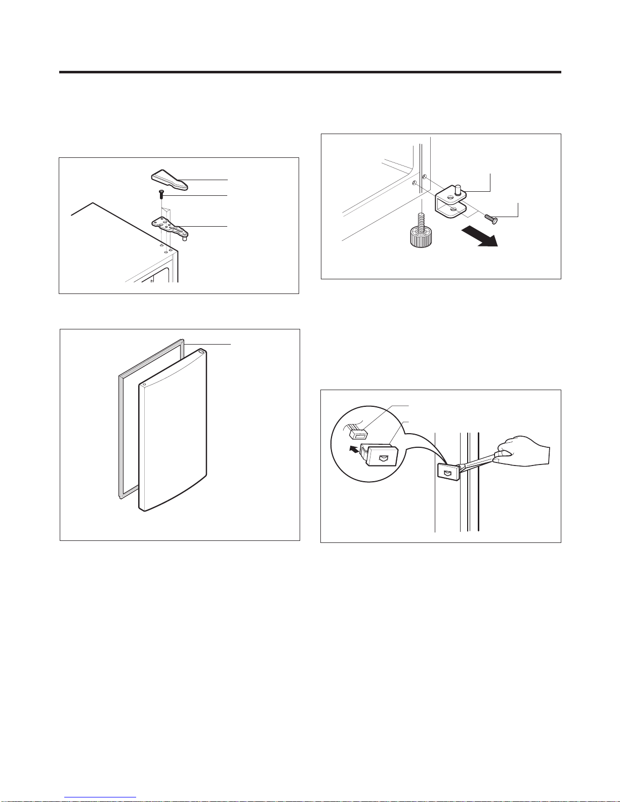
3-1 DOOR
Refrigerator Door
1. Remove the hinge cover by pulling it upwards.
2. Loosen the hexagonal bolts attaching the upper hinge to
the body and lift the freezer door.
HINGE COVER
BOLT
HINGE
Figure 1
3. Pull out the door gasket to remove from the door foam
assembly.
GASKET
Freezer Door
1. Loosen the hexagonal bolts attaching the lower hinge to
the body to remove the refrigerator door only.
LOWER HINGE
BOLT
Figure 3
2. Pull out the door gasket to remove from the door foam
assembly.
3-2 DOOR SWITCH
1. To remove the door switch, pry it out with a slotted-type
driver, as shown in (Figure 4).
2. Disconnect the lead wire from the switch.
Figure 2
LEAD WIRE
DOOR SWITCH
Figure 4
-
-
6
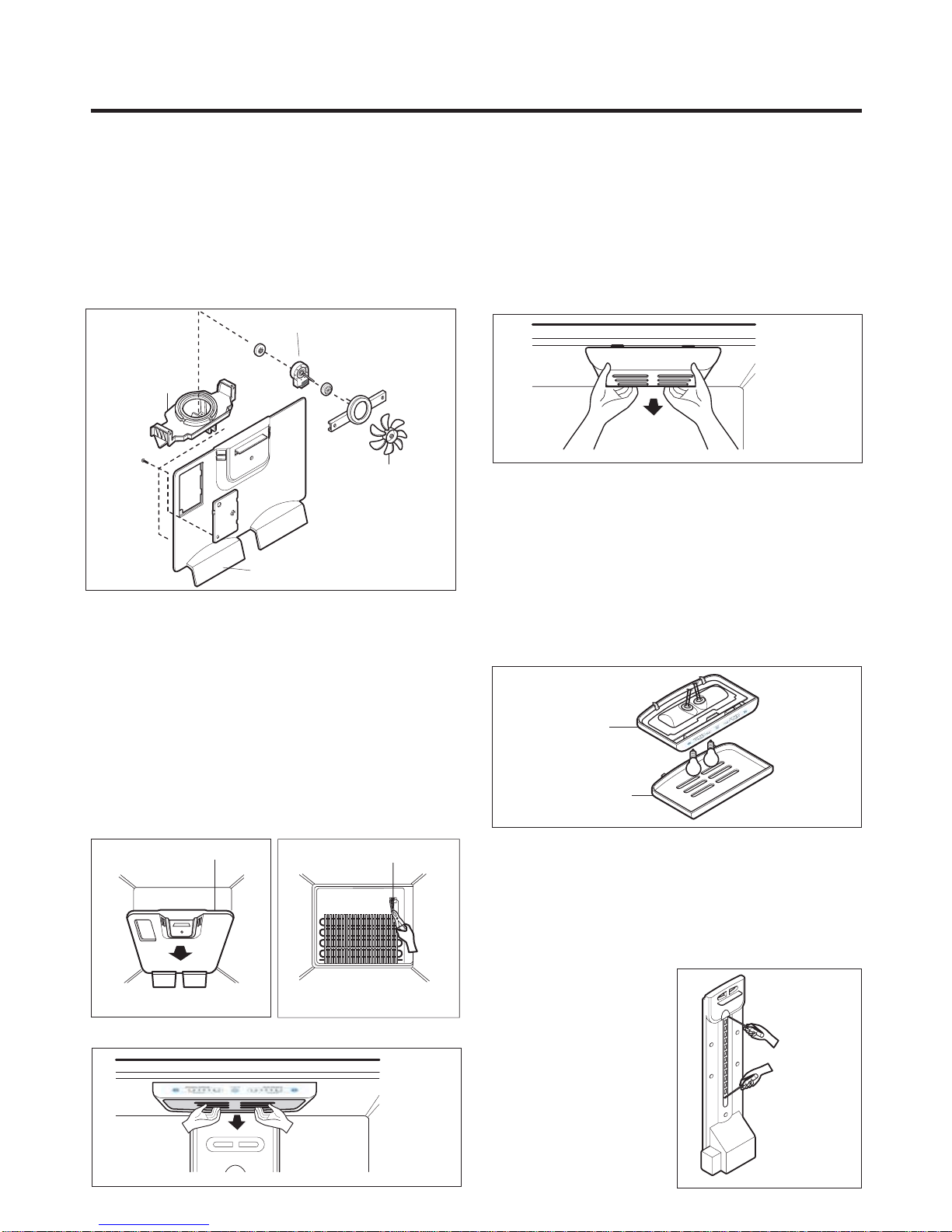
3-3 FAN AND FAN MOTOR
1. Remove the freezer shelf. (If your refrigerator has an
icemaker, remove the icemaker first)
2. Remove the grille by pulling it out and by loosening a
screw.
3. Remove the Fan Motor assembly by loosening 2 screws
and disassemble the shroud.
4. Pull out the fan and separate the Fan Motor and Bracket.
5. Pull out the fan and separate the Fan Motor and Bracket.
FAN MOTOR
BRACKET
MOTOR
FAN
GRILLE
Figure 11
3-4 DEFROST CONTROL ASSEMBLY
Defrost Control assembly consists of Defrost Sensor and
FUSE–M.
The Defrost Sensor works to defrost automatically. It is
attached to the metal side of the Evaporator and senses its
Temperature.
Fuse-M is a safety device for preventing over-heating of
the Heater when defrosting.
At 72°C, it turns the Defrost Heater off.
1. Pull out the grille assembly. (Figure 6)
2. Separate the connector with the Defrost Control
assembly and replace the Defrost Control assembly
after cutting the Tie Wrap. (Figure 7)
3-5-1 Refrigerator Compartment Lamp
1. Unplug the power cord from the outlet.
2. Remove refrigerator shelves.
3. Release the hooks on both ends of the lamp shield and
pull the shield downward to remove it.
4. Turn the lamp counterclockwise.
5. Assemble in reverse order of disassembly. Replacement
bulb must be the same specification as the original
(Max. 60 W-2EA).
Figure 9
3-5-2 Freezer Compartment Lamp
1. Unplug refrigerator or disconnect power.
2. Reach behind light shield to remove bulb.
3. Replace bulb with a 0-watt appliance bulb.6
4. Plug in refrigerator or reconnect power.
3-6 CONTROL BOX-REFRIGERATOR
1. First, remove all shelves in the refrigerator, than remove
the Refrigerator control Box by loosening 2 screws.
CONTROL BOX
COVER LAMP
Figure 10
GRILLE ASSEMBLY
DEFROST-CONTROL
ASSEMBLY
Figure 6
3-5 LAMP
Figure 7
Figure 8
2. Remove the Refrigerator Control Box by pulling it
downward.
3. Disconnect the lead wire on the right position and
separate the lamp sockets.
3-7 MULTI DUCT
1. Remove an upper and
lower Cap by using a flat
screwdriver, and loosen 3
screws. (Figure 11)
2. Disconnect the lead wire
on the bottom position.
Figure 11
- 7 -
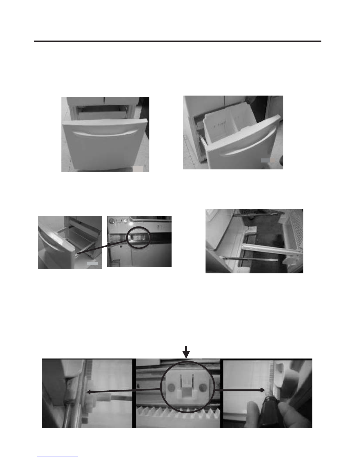
3-8 HOW TO REMOVE AND REINSTALL THE PULLOUT DRAWER
3-8-1 FOLLOW STEPS TO REMOVE
Step 1) Open the freezer door.
Step 3) Remove the two screws from the guide rails (one
from each side).
Step 2) Remove the lower basket.
Step 4) Lift the freezer door up to unhook it from the rail
support and remove.
Pull both rails to full extension.
Step 5) First: Remove the gear from the left side first by releasing the tab behind the gear, place a screwdriver between the
gear and the tab and pull up on the gear.
Second: Remove the center rail.
Third: Remove the gear from the right side by following the same steps for the left side.
NOTE: THIS TAB MUST BE PUSHED IN TO RELEASE THE GEAR.
- 8 -
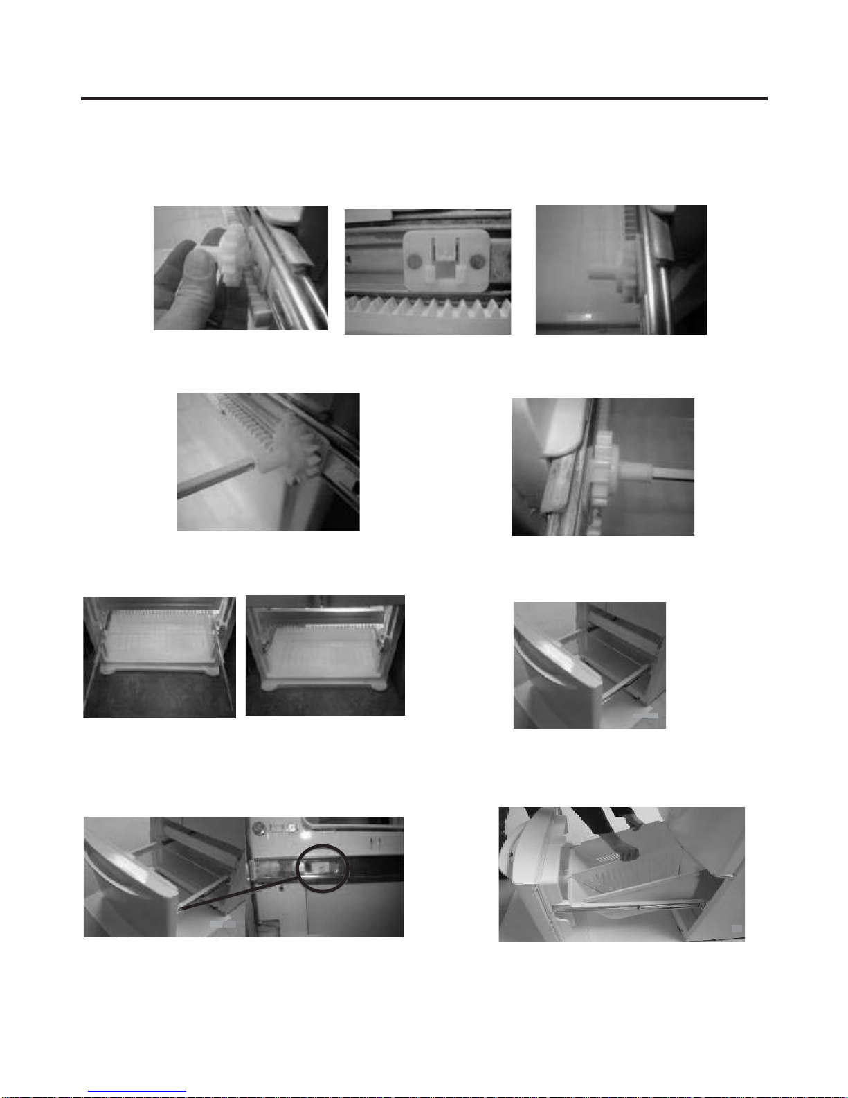
3-8-2 FOLLOW STEPS TO REINSTALL
Step 1) Reinstall the right side gear into the clip.
Step 2) Insert the rail into the right side gear. Gears do not
need to be perpendicular to each other.
Step 4) The rail system will align itself by pushing the rails
all the way into the freezer section.
Pull the rails back out to full extension.
Step 3) Insert the rail into the left side gear, and insert the
gear into the clip.
Step 5) Reinstall the freezer door by inserting the rail tabs
into the guide rail.
Step 6) Reinstall the two screws into the guide rails
(one from each side).
Step 7) Reinstall the lower basket, and close the freezer
door.
- 9 -
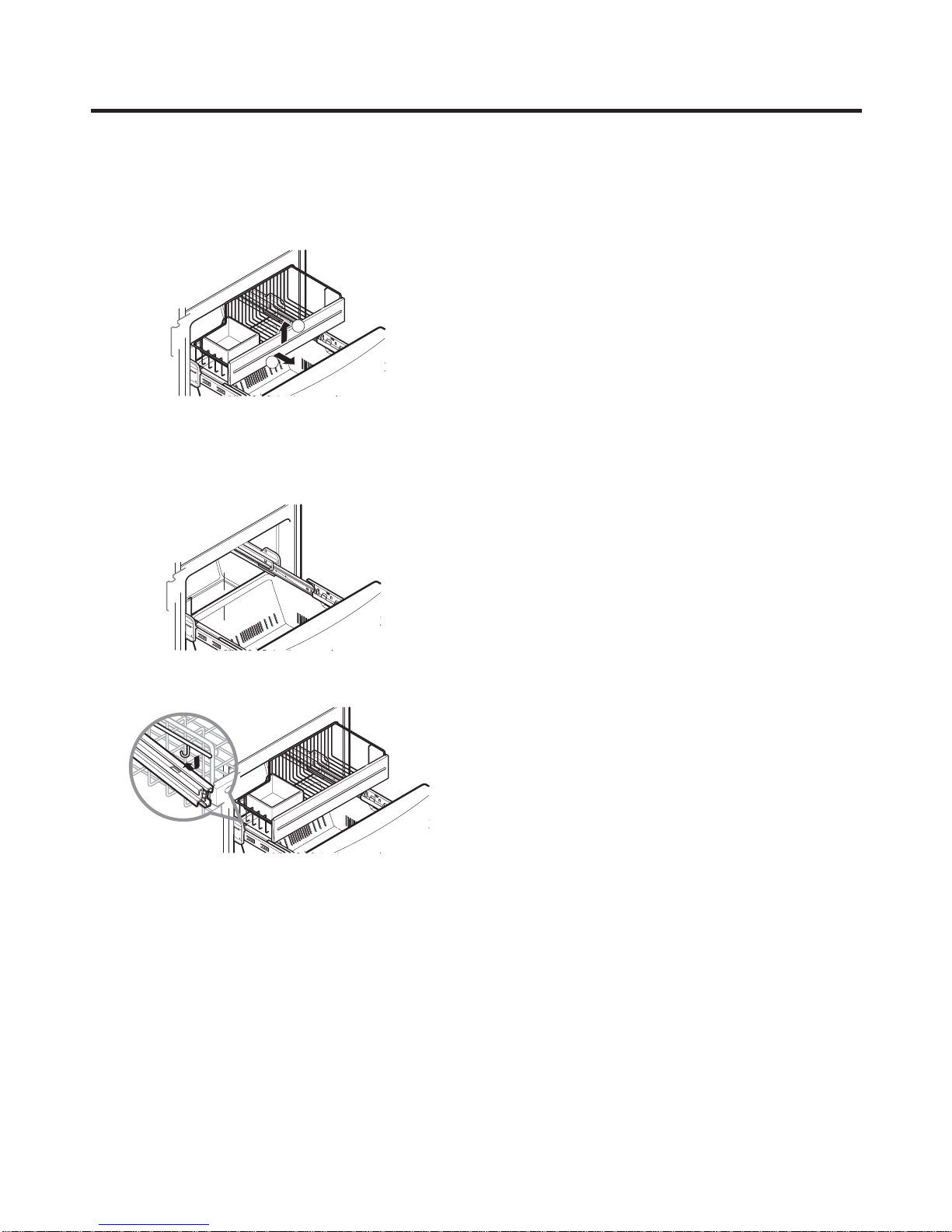
3.8.3 GLIDE OUT DRAWER BASKET
-
To remove, lift basket up and pull out straight out.
1
2
2.1.To Install, pull both rails out to full extension.
Hook the basket supports into the rail tabs and push to
the back of compartment.
- 10 -
3-9 Cover Valve
- Disassemble
1. Push to inside the cover valve.
- Assemble
1. Insert the cover valve as shown in the picture, push to
insert (may need force).
a
b
2. Push to the right and release.
a
b
3. Release hook a & b
4. Turn the cover valve 120° as shown in the picture, then
release it.
2. Insert hook a & b
3. Push to the right to insert the cover valve.
4. Then push to inside to assembly.
- 11 -
4. ADJUSTMENT
4-1 COMPRESSOR
4-1-1 Role
The compressor intakes low temperature and low pressure
gas from the evaporator of the refrigerator and compresses
this gas to high-temperature and high-pressure gas. It then
delivers the gas to the condenser.
4-1-2 Composition
The compressor includes overload protection. The PTC
starter and OLP (overload protector) are attached to the
outside of the compressor. Since the compressor is
manufactured to tolerances of 1 micron and is hermetically
sealed in a dust and moisture-free environment, use
extreme caution when repairing it.
4-1-3 Note for Usage
(1) Be careful not to allow over-voltage and over-current.
(2) If compressor is dropped or handled carelessly, poor
operation and noise may result.
(3) Use proper electric components appropriate to the
Particular Compressor in your product.
(4) Keep Compressor dry.
If the Compressor gets wet (in the rain or a damp
environment) and rust forms in the pin of the Hermetic
Terminal, poor operation and contact may result.
(5) When replacing the Compressor, be careful that dust,
humidity, and soldering flux don’t contaminate the inside
of the compressor. Dust, humidity, and solder flux
contaminate the cylinder and may cause noise,
improper operation or even cause it to lock up.
4-2 PTC-STARTER
4-2-1 Composition of PTC-Starter
(1) PTC (Positive TemperatureCoefficient) is a no-contact
semiconductor starting device which uses ceramic
material consisting of BaTiO
(2) The higher the temperature is, the higher the resistance
value. These features are used as a starting device for
the Motor.
4-2-2 Role of PTC-Starter
(1) The PTC is attached to the Sealed Compressor and is
used for starting the Motor.
(2) The compressor is a single-phase induction motor.
Durign the starting operation, the PTC allows current
flow to both the start winding and main winding.
3.
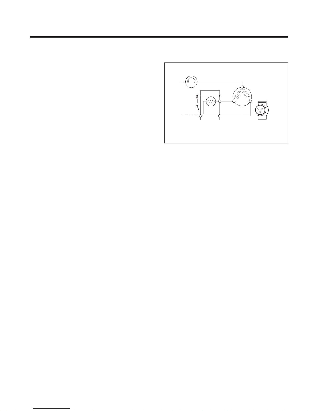
4-2-3 PTC-Applied Circuit Diagram
Starting Method for the Motor
OVERLOAD PROTECTOR
N
PTC
2
L1
Resistance Starter Capacitor Running
3
PTC STARTER
5
6
C
COMPRESSOR
MOTOR
S
M
S
SEALED
TERMINAL
M
Figure 12
4-2-4 Motor Restarting and PTC Cooling
(1) It requires approximately 5 minutes for the pressure to
equalize before the compressor can restart.
(2) The PTC device generates heat during operation.
Therefore, it must be allowed to cool before the
compressor can restart.
4-2-5 Relation of PTC-Starter and OLP
(1) If the compressor attempts to restart before the PTC
device is cooled, the PTC device will allow current to
flow only to the main winding.
(2) The OLP will open because of the over current
condition. This same process will continue (3 to 5
times) when the compressor attempts to restart until
the PTC device has cooled. The correct OLP must be
properly attached to prevent damage to the
compressor.
Parts may appear physically identical but could have
different electrical ratings. Replace parts by part
number and model number. Using an incorrect part
could result in damage to the product, fire, injury, or
possibly death.
4-2-6 Note for Using the PTC-Starter
(1) Be careful not to allow over-voltage and over-current.
(2) Do not drop or handle carelessly.
(3) Keep away from any liquid.
If liquid such as oil or water enters the PTC,
PTC materials may fail due to breakdown of their
insulating capabilities.
(4) If the exterior of the PTC is damaged, the resistance
value may be altered. This can cause damage to the
compressor and result in a no-start or hard-to-start
condition.
(5) Always use the PTC designed for the compressor and
make sure it is properly attached to the compressor.
Parts may appear physically identical but could have
different electrical ratings. Replace parts by part
number and model number. Using an incorrect part
could result in damage to the product, fire, injury, or
possibly death.
- 12 -
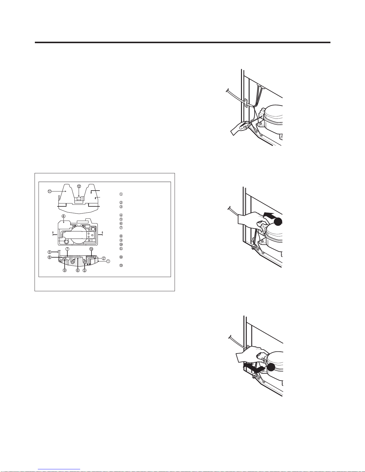
4-3 OLP (OVERLOAD PROTECTOR)
4-3-1 Definition of OLP
(1) OLP (OVERLOAD PROTECTOR) is attached to the
Compressor and protects the Motor by opening the
circuit to the Motor if the temperature rises and
activating the bimetal spring in the OLP.
(2) When high current flows to the Compressor motor, the
Bimetal works by heating the heater inside the OLP,
and the OLP protects the Motor by cutting off the
current flowing to the Compressor Motor.
4-3-2 Role of the OLP
(1) The OLP is attached to the Sealed Compressor used
for the Refrigerator. It prevents the Motor Coil from
being started in the Compressor.
(2) For normal operation of the OLP, do not turn the Adjust
Screw of the OLP in any way.
(OVERLOAD PROTECTORcross section)
Part
No. Name
Base, phenolic
(UL 94 V-0 rated)
Movable armsupport, plated steel
Stationary contact support,
platedsteel
Heater support,plated steel
Heater, resistance alloy
Disc, thermostaticalloy
Movable arm, spring temper
copperalloy
Contact, movable, silveron copper
Contact, stationary, silver on copper
Slug, platedsteel
Cover, polyester
(UL 94 V -0 rated)
Pinconnector, platedcopper alloy
(To engage 2.33/2.66 mm dia. pin)
Quick-connect terminal,brass,
conforms to UL 310, MEMA
DC-2, DIN 46344
Figure 13
Electrical
characteristics
part number
12345678
330 FBYY -S1 BOX98
Customer part
number
Lot code/
date code
Physical
termination
part number
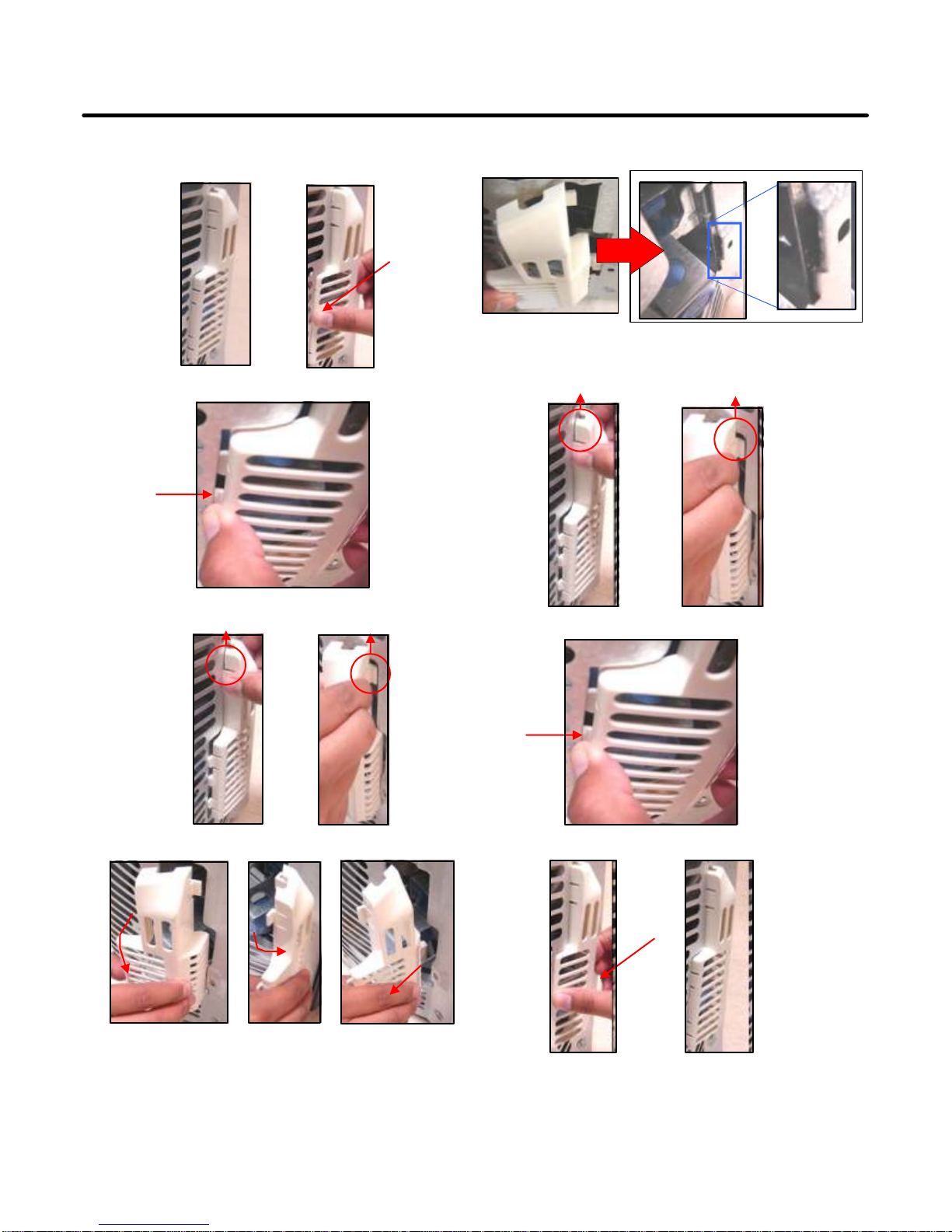
4-4 TO REMOVE THE COVER PTC
1) Remove the Cover Back M/C.
(2) Remove the screw on Cover PTC.
1
(3) Remove two Housings on upper part of Cover PTC.
(4) Take out the cover PTC from upper to lower position
like ( 1 ).
2
(5) Turn 45¡ in the direction of (2)and take it out.
(6) Assembly in reverse order of disassembly.
- 13 -
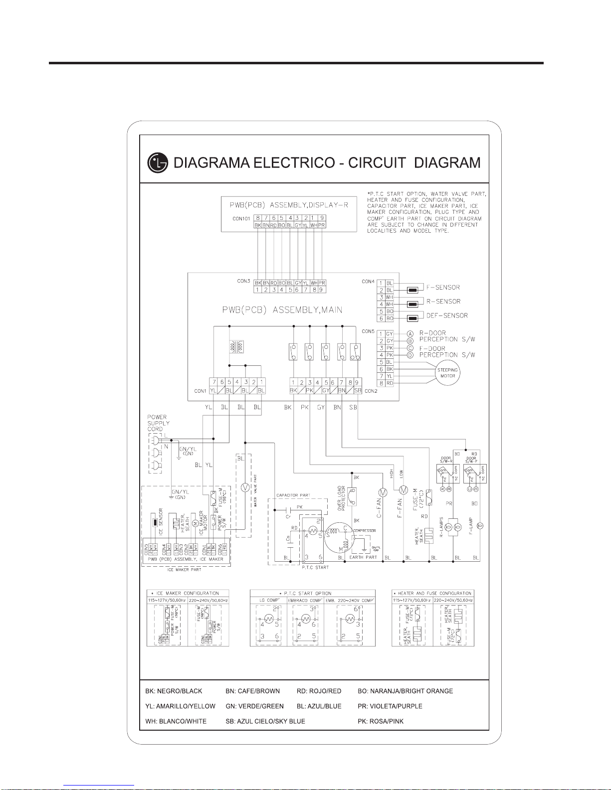
5. CIRCUIT DIAGRAM
Good / Better
GY: GRIS/GRAY
- 14 -
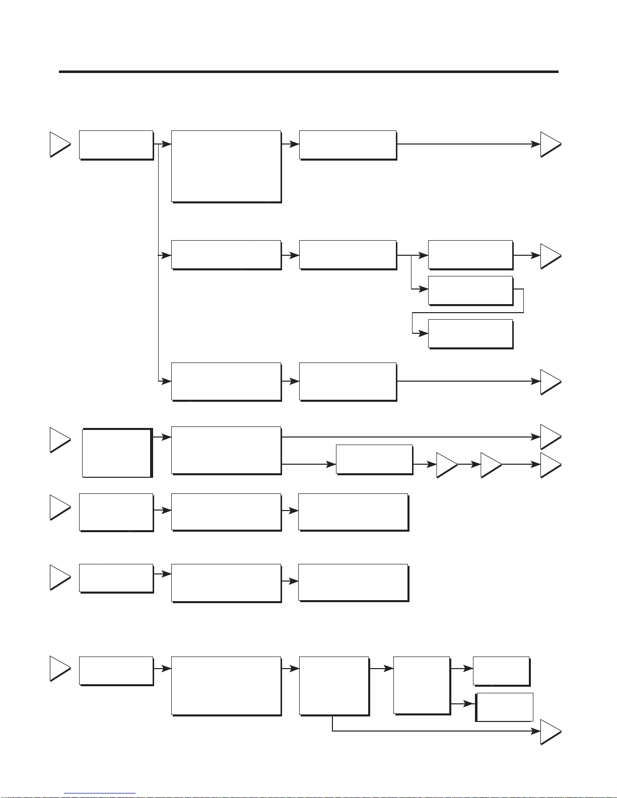
6. TROUBLESHOOTING
6-1 COMPRESSOR AND ELECTRIC COMPONENTS
1
Power Source.
Remove PTC-Starter
from compressor and
measure voltage
between Terminal C of
compressor and
terminal 5 or 6 of PTC.
No voltage.
Applied voltage isn't
in acceptable range.
(115V ±10%)
(Rated voltage
±10%)?
YES
OLP disconnected?
NO
Advise customer that
power supply needs to be
checked by an electrician.
YES
Replace OLP.
Check connection
condition.
Reconnect.
2
5
5
2
3
4
5
Check
Check resistance
resistance of
of motor
motor
compressor.
compressor.
.
Check
resistance of
PTC-Starter.
Check OLP.
Check
starting state.
Check the resistance
between M-C, S-C and
M-S in motor compressor.
Check resistance of
two terminals in
PTC-Starter.
Check resistance of two
terminals in OL.P
Check the power supply
under load.
(Compressor attempting
to re-start after being off
for 5 minutes).
Open or short
Refer to Page 12.
Refer to Page 12.
Supply
voltage rating
with ±10%.
The range of resistance is between 1~50 ? (ok)
Replace
compressor
YES
Did
compressor
start?
YES
NO
43
Compressor
is OK
Replace the
compressor
3
5
- 1 5 -
NO
1

6-2 PTC AND OLP
Normal operation of
compressor is impossible
or poor.
Separate PTC-Starter
from Compressor and
measure resistance
between No. 5 and 6
of PTC-Starter with a
Tester.
(Figure 19)
Separate OLP from
compressor and check
resistance value between
two terminals of OLP whit a
tester.
(Figure 20)
65
?
Observation value is
115V/60Hz : 6.8 ? ±?0%
The resistance value
is 0 ? (short) or
8(open).
Shows continuity
Open
Check another
electric component.
Replace OLP
.
Replace PTCStarter.
Figure 19
Figure 20
- 1 6 -
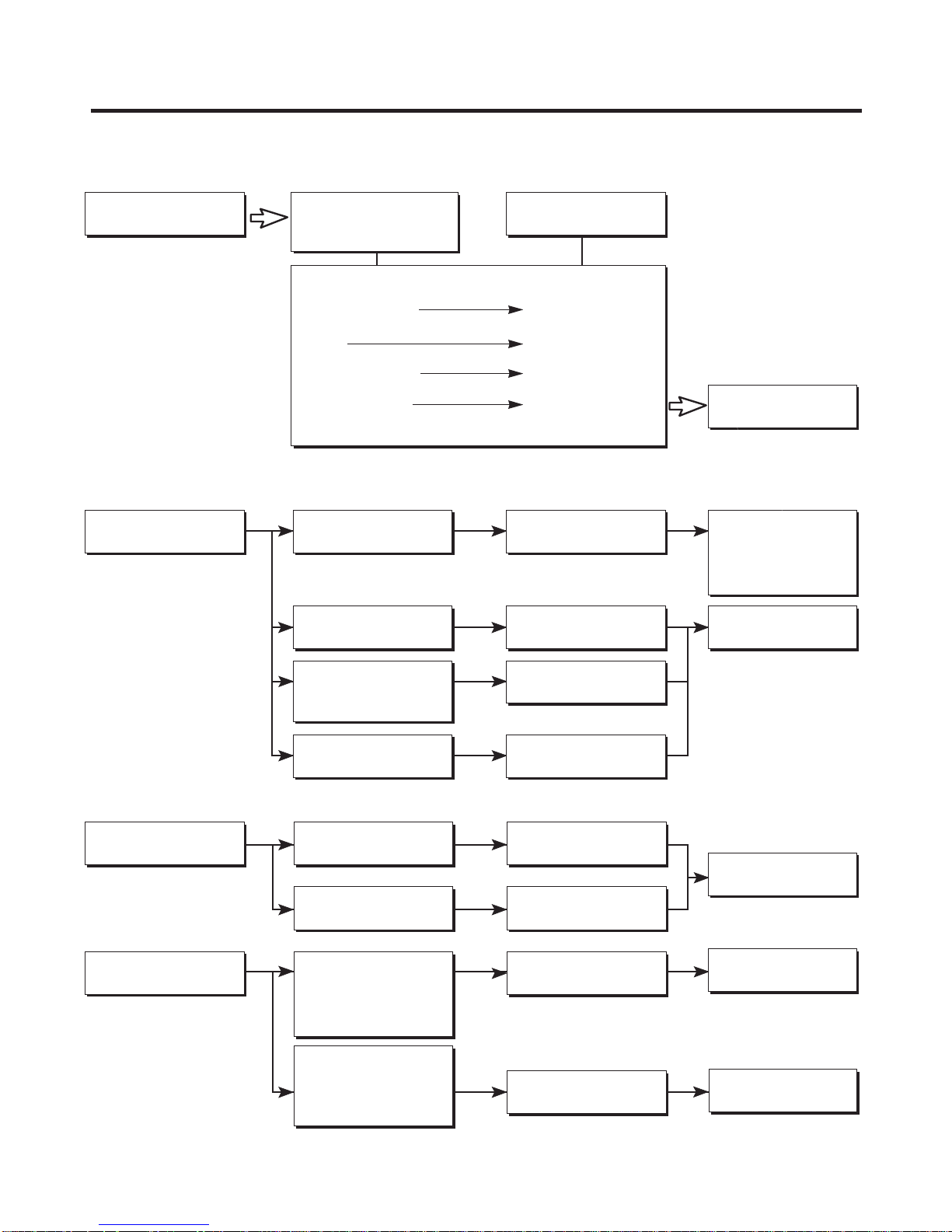
6-3 OTHER ELECTRICAL COMPONENTS
Not cooling at all
Compressor
doesn't run.
Poor cooling performance
Compressor runs
poorly.
Checkfor open short or
incorrect resistance readings
in the followingcomponents
a. Starting devices
b. OLP
c. Compressor coil
d. Wiring harness
Check starting
voltage.
Check voltage at
starting devices.
Cause
Short, open, or broken.
Poor contact
or shorted.
Coil open or shorted.
Poor contact
or shorted.
Low voltage.
Poor or broken or
open contact.
Replace
indicatedcomponent.
Advise customer that
the power supply
needs to be checked
by an electrician.
Replace
indicatedcomponent.
Fan motor
doesn't run.
Heavy frost buildup on
evaporator
Check current flowing
in sub-coil of
Compressor.
Check rating of OLP.
Check wiring circuit.
Check Fan Motor.
Check current flow in
the following
components:
Sensor
Fuse-M
Check current flow in
the defrost heater.
Shorted.
Lack of capacity.
Wire is open or
shorted.
Coil is shorted
or open.
Open.
Open.
Replace
indicatedcomponent.
Replace
indicatedcomponent.
Replace
defrostheater.
- 1 7 -
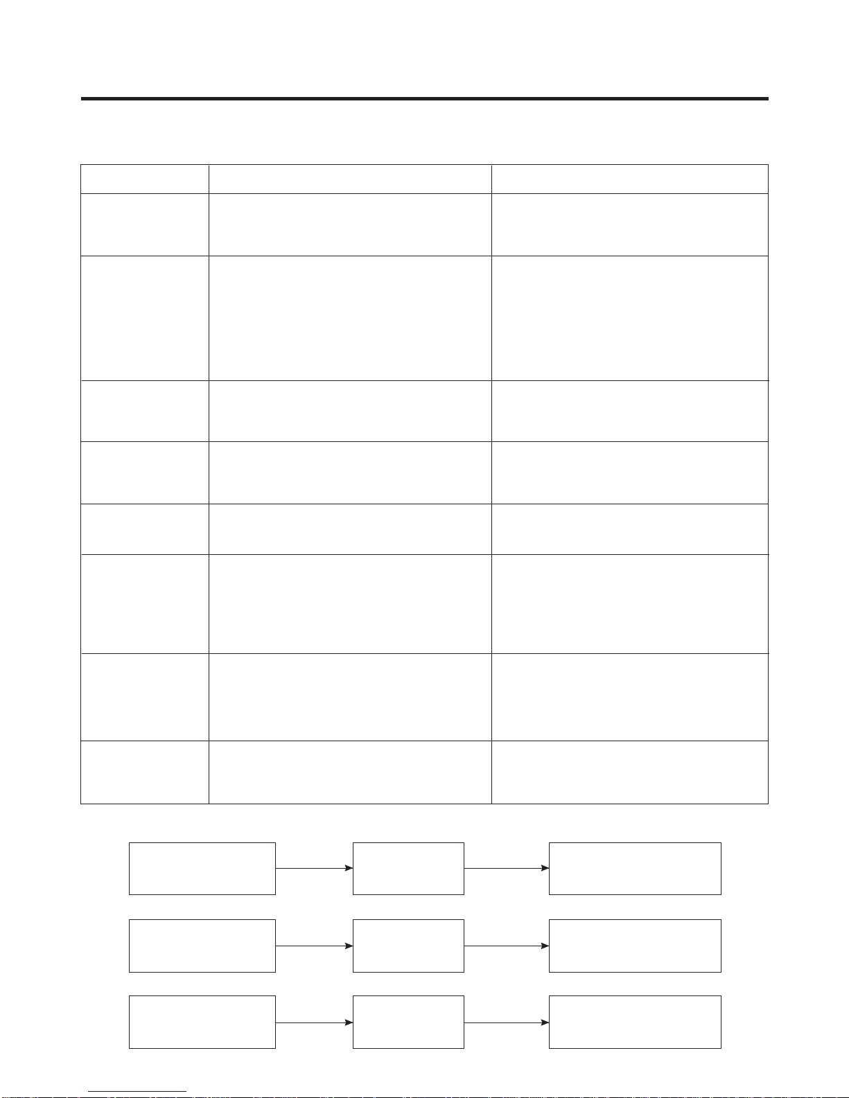
6-4 SERVICE DIAGNOSIS CHART
COMPLAINT POINTS TO BE CHECKED REMEDY
No Cooling.
Cools poorly.
Foods in the
Refrigerator
are frozen.
Condensartion or ice
forms inside
the unit.
Condensartion forms
in the Exterior Case.
There is abnormal
noise.
• Is the power cord unplugged from the outlet?
• Check if the power switch is set to OFF.
• Check if the fuse of the power switch is shorted.
• Measure the voltage of the power outlet.
• Check if the unit is placed too close to the wall.
• Check if the unit is placed too close to the stove,
gas cooker, or in direct sunlight.
• Is the ambient temperature too high or
the room door closed?
• Check if food put in the refrigerator is hot.
• Did you open the door of the unit too often
or check if the door is sealed properly?
• Check if the Control is set toWarm position .
• Is food placed in the cooling air outlet?
• Check if the control is set tocolder position .
• Is the ambient temperature below 41°F(5°C)?
• Is liquid food sealed?
• Check if food put in the refrigerator is hot.
• Did you open the door of the unit too
often or check if the door is sealed properly?
• Check if the ambient temperature and humidity
of the surrounding air are high.
• Is there a gap in the door gasket?
• Is the unit positioned in a firm and even place?
• Are any unnecessary objects placed
in the back side of the unit?
• Check if the Tray Drip is not firmly fixed.
• Check if the cover of the compressor enclosure
in the front lower side is taken out.
• Plug into the outlet.
• Set the switch to ON.
• Replace the fuse.
• If the voltage is low, correct the wiring.
• Place theunit about 4 inches (10cm) fromthe wall.
• Place the unit away from these heat sources.
• Lower the ambient temperature.
• Put in foods after they have cooled down.
• Don't open the door too often and close
it firmly.
• Set the control toRecommended position .
• Place foods in the high-temperature section.
(front part)
• Set the control toRecommended position .
• Set the control toWarm position .
• Seal liquid foods with wrap.
• Put in foods after they have cooled down.
• Don't open the door too often and close
it firmly.
• Wipe moisture with a dry cloth. It will disappear
in low temperature and humidity.
• Fill up the gap.
• Adjust the Leveling Screw, and position the
refrigerator in a firm place.
• Remove the objects.
• Fix the Tray Drip firmly in the original position.
• Place the cover in its original position.
Door does not
close well.
Ice and foods
smell unpleasant.
• Check if the door gasket is dirty with
• Is the refrigerator level?
• Is there too much food in the refrigerator?
• Check if the inside of the unit is dirty.
• Are foods with a strong odor unwrapped?
• The unit smells of plastic.
Other possible problems:
Check if frost forms in
the freezer.
Check the
refrigeration system.
Check the
Thermistor.
an item like juice.
Not
defrosting
The system
is faulty.
The operation of
the Thermistor is
incorrect.
• Clean the door gasket.
• Position in the firm place and level the
Leveling Screw.
• Make sure food stored in shelves does not prevent
the door from closing.
• Clean the inside of the unit.
• Wrap foods that have a strong odor.
• New products smell of plastic, but this
will go away after 1-2 weeks.
Check Components
of the defrosting
circuit.
Perform sealed
system repair.
Replace the
Thermistor.
- 18 -

6-5 REFRIGERATION CYCLE
* Troubleshooting Chart
CAUSE
PARTIAL
LEAKAGE
L
EAK G
A
E
COMPLETE
LEAKAGE
C OGG
L E
PARTIAL
CLOG
D
B
Y DU T
WHOLE
CLOG
S
MOISTURE
CLOG
COM
COMPRE-
DE
SSION
P
F
E
R
C
E
T V
SS ON
NO
I E
I
COMPRESSION
STATE OF
THE UNIT
Freezer
compartment and
refrigerator don• t
cool normally
Freezer
compartment and
refrigerator don• t
cool normally
Freezer
compartment and
refrigerator don• t
cool normally
Freezer
compartment and
refrigerator don• t
cool.
Cooling operation
stops periodically.
Freezer and
refrigerator don• t
cool.
No compressing
operation.
STATE OF THE
EVAPORATOR
Low flowing sound of
refrigerant is heard and frost
forms in inlet only.
Flowing sound of refrigerant
is not heard and frost isn• t
formed.
Flowing sound of refrigerant
is heard and frost forms in
inlet only.
Flowing sound of refrigerant is
not heard and frost isn• t
formed.
Flowing sound of refrigerant is
not heard and frost melts.
Low flowing sound of
refrigerant is heard and frost
forms in inlet only.
Flowing sound of refrigernat is
not heard and there is no
frost.
TEMPERATURE
OF THE
COMPRESSOR
A little higher than
ambient
temperature.
Equal to ambient
temperature.
A little higher than
ambient
temperature.
Equal to ambient
temperature.
Lower than ambient
temperature.
Alittle higher than
ambient
temperature.
Equal to ambient
temperature
REMARKS
- Refrigerant level is low due to a
leak.
¥
- Normal cooling is possible by
restoring the normal amount of
¥
refrigerant and repairing the leak.
¥
- No discharging of refrigerant.
- Normal cooling is possible by
restoring the normal amount of
¥
refrigerant and repairing the leak.
¥
- Normal discharging of the
refrigerant.
¥
- The capillary tube is faulty.
- Normal discharging of the
refrigerant.
¥
- Cooling operation restarts when
heating the inlet of the capillary
¥
tube.
¥
- Low pressure at high side of
compressor due to low
¥
refrigerant level.
¥
- Nopressure in the high pressure
Part of the compressor.
¥
¥
- 19 -
 Loading...