

Kenmore 790.7942 User Manual
Gas Range
Estufa a gas
Models, Modelos 790.7942 *, 7944*
* = color number, número de color
rn
:g
«í
r
www.sears.com Sears Roebuck and Co., Hoffman Estates, IL 60179 U.S.A.
rn
■
:*o
O
1“
p/n 316417324 (0606)

Table of Contents
Freestanding Range Warranty
IMPORTANT SAFETY INSTRUCTIONS ..................................... 3-5
Protection Agreements............................................................6
Before Using Your Range .............
Range Features
Before Setting Oven Controls
Before Setting Surface Controls.......................................... 10
Surface Cooking .......................................................... 11-13
Setting Warmer Drawer & Controls
Electronic Oven Control Pad Features
Minimum & Maximum Control Pad Settings
Setting Oven Controls......................................................17-31
Setting the Clock........................................................ 17
Changing between 12 or 24 Hour Display
Silent Control Operation
Continuous Bake or 12 Hour Energy Saving Mode
Timer........................................................................... 18
Oven Lockout............................................................. 19
Changing Temperature Display
..
Saying
........................................................................
.&.
R®S§!liD3
................................................
..............................................................................................................................
............................................9-10
.................................
...........................
......................
...............
...........................................
....................................
....
3§SiB§................................2Q
13-15
16
16
17
17
....
18
19
2
8
Setting Preheat.................................................................21
Setting Bake......................................................................22
Setting Cook Time.............................................................23
Setting Delay Start.............................................................24
Setting Broil & Searing Grill ..............................................25
Setting Convection Roast .................................................26
Setting Cakes and Breads.................................................26
Setting Convection Bake
Setting Convection Convert...............................................28
Setting Add 1 Minute Feature............................................28
Setting Siow Cook.............................................................29
Setting the Sabbath Feature........................................30-31
Setting Warm & Hold
Self-Cleaning.......................................................................32-34
Adjusting Oven Temperature....................................................35
General Care & Cleaning
Before You Call for Service.................................................41-42
Recipes for Slow Cook.............................................................43
Sears Service ...................................
...................................................
........................................................
....................................................
..................
7
...... back cover
.
36-40
Kenmore Elite Appliance Warranty
One Year Limited Warranty
When installed, operated and maintained according to all instructions supplied with the product, if this appliance fails due to
a defect in material or workmanship within one year from the date of purchase, call 1-800-4-MY-HOME ® to arrange for free
repair. If this appliance is used for other than private family purposes, this warranty applies for only 90 days from the date of
purchase.
27
31
This warranty covers only defects in material and workmanship. Sears will NOT pay for:
1. Expendable items that can wear out from normal use, including but not limited to filters, belts, light bulbs, and bags.
2. A service technician to instruct the user in correct product installation, operation or maintenance.
3. A service technician to clean or maintain this product.
4. Damage to or failure of this product if it is not installed, operated or maintained according to all instructions supplied with
the product.
5. Damage to or failure of this product resulting from accident, abuse, misuse or use for other than its intended purpose.
6. Damage to or failure of this product caused by the use of detergents, cleaners, chemicals or utensils other than those
recommended in all instructions supplied with the product.
7. Damage to or failure of parts or systems resulting from unauthorized modifications made to this product.
FIVE-YEAR LIMITED WARRANTY
For five years from the date of purchase, when this range is installed, operated, and maintained according to all instructions
supplied with this product, Sears will replace the following range parts free of charge if they fail for the reasons below.
Customer must pay labor cost of installation.
• Cooktop glass if it fails due to thermal shock.
• Cooktop elements if they are defective.
Disclaimer of implied warranties; limitation of remedies
Customer’s sole and exclusive remedy under this limited warranty shall be product repair as provided herein. Implied
warranties, including warranties of merchantability or fitness for a particular purpose, are limited to one year or the shortest
period allowed by law. Sears shall not be liable for incidental orconsequentiai damages. Some states and provinces do not
allow the exclusion or limitation of incidental orconsequentiai damages, or limitations on the duration of implied warranties of
merchantability or fitness, so these exclusions or limitation may not apply to you.
This warranty applies only while this appliance is used in the United States and Canada.
This warranty gives you specific legal rights, and you may also have other rights which vary from state to state.
Sears, Roebuck and Co., Dept. 817WA, Hoffman Estates, IL 60179 Sears Canada Inc., Toronto, Ontario, Canada MSB 2B8

important Safety instructions
Read all instructions before using this appliance. Save these instructions for future reference.
This manual contains important safety symbols and instructions. Please pay attention to these symbols and follow all instructions given.
A WARNING
4Û^CAUTI0N
WARNING
I
This symbol will help alert you to situations that may cause serious bodily harm, death or property damage.
This symbol will help alert you to situations that may cause bodily injury or property damage. : : ^ : :;; ;
If the information in this manuai is not
foiiowed exactiy, a fire orexpiosion may resuit
causing property damage, personal injury or death.
FORYOURSAFETY:
— Do not store or use gasoline or other flammable
vapors and liquids in the vicinity of this or any
otherappliance.
— WHAT TO DO IF YOU SMELL GAS:
• Do not try to light any appliance.
• Do not touch any electrical switch; do not use
any phone in your building.
• Immediately call your gas supplier from a
neighbor's phone. Follow the gas supplier's
instructions.
• If you cannot reach your gas supplier, call the
fire department.
— Installation and service must be performed by a
qualified installer, servicer or the gas supplier.
Ü^WARNING
All ranges can tip.
Injury to persons could result.
Install anti-tip device packed with range.
See Installation Instructions.
i^WARNING
To reduce the risk of
tipping, the range must be secured by
properly installed anti-tip bracket provided
with the range. To check if the bracket is
installed properly, visually check that rear
leveling leg is inserted into and fully
secured by the anti-tip bracket by
removing lower panel or storage drawer.
For models with a warmer drawer, grasp
the top rear edge of the range and
carefully attempt to tilt it forward. Refer to
the installation instructions for proper anti
tip bracket installation.
■ Remove all tape and packaging before using the range.
Destroy the carton and plastic bags after unpacking the range.
Never allow children to play with packaging material.
' Proper installation—Be sure your appliance is properly
installed and grounded by a qualified technician in
accordance with the National Fuel Gas Code ANSI Z223.latest edition, orin Canada CAN/CGAB149.1, and CAN/CGA
B149.2, andthe the National Electrical Code ANSI/NFPA
No.70-latest edition, or in Canada CSA Standard C22.1,
Canadian Electrical Code, Part 1, and local code
requirements. Install only per installation instructions
provided in the literature package for this range.
Ask your Sears dealer to recommend a qualified technician
and an authorized Sears repair service. Know how to
disconnect the power to the range at the circuit breaker or
fuse box in case of an emergency.
' User servicing—Do not repair or replace any part of the
appliance unless specifically recommended in the manuals.
All other servicing should be done only by a qualified
technician. This may reduce the risk of persona! injury and
damage to the range.
■ Never modify or alter the construction of a range by
removing leveling legs, panels, wire covers, anti-tip
brackets/screws, or any other part of the product.
' Air curtain or other overhead range hoods, which operate
by blowing a downward airflow on to a range, shall not be
used in conjunction with gas ranges other than when the
hood and range have been designed, tested and listed by an
independent test laboratory for use in combination with
each other.
A WARNING
drawers of this range can result in serious injuries and also
cause damage to the range. Do not allow children to climb or
play around the range. The weight of a child on an open door
may cause the range to tip, resulting in serious burns or other
injury.
A WARNING
Stepping, leaning or sitting on the doors or
NEVER use this appliance as a space
heater to heat or warm the room. Doing so may result in
carbon monoxide poisoning.
A WARNING
NEVER cover any slots, holes or passages in
the oven bottom or cover an entire rack with materials such as
aluminum foil. Doing so blocks air flow through the oven and
may cause carbon monoxide poisoning. Aluminum foil linings
may trap heat, causing a fire hazard.
A WARNING
equipped) for storage.
• Storage in or on Appliance—Flammable materials should
not be stored in an oven, warmer drawer, near surface
burners or in the storage drawer. This includes paper, plastic
and cloth items, such as cookbooks, plastic ware and towels,
as well as flammable liquids. Do not store explosives, such as
aerosol cans, on or near the range.
Acaution
the cabinets above a range or on the backguard of a range.
Children climbing on the range to reach items could be
seriously injured.
Do not use the oven or warmer drawer (if
Do not store items of interest to children in

important Safety instructions
• Do Not Leave Children Alone—Children should not be left
alone or unattended in the area where appliance is in use.
They should never be allowed to sit or stand on any part of the
appliance.
• DO NOTTOUCHSURFACE BURNERS, AREASNEARTHESE
BURNERS,OVEN BURNERS ORINTERIORSURFACESOFTHE
OVEN. Both surface and oven burners may be hot even though
flames are not visible. Areas near surface burners may
become hot enough to cause burns. During and after use, do
not touch, or let clothing or other flammable materials touch
these areas until they have had sufficient time to cool. Among
these areas are the cook top, surfaces facing the cook top, the
oven vent openings and surfaces near these openings, oven
door and window.
• Wear Proper Apparel—Loose-fitting or hanging garments
should never be worn while using the appliance. Do not let
clothing or other flammable materials contact hot surfaces.
• Do Not Use Water or Flour on Grease Fires—Smother the
fire with a pan lid, or use baking soda, a dry chemical or
foam-type extinguisher.
• When heating fat or grease, watch it closely. Fat or grease
may catch fire if allowed to become too hot.
• Use Only Dry Potholders—Moist or damp potholders on hot
surfaces may result in burns from steam. Do not let
potholders touch hot heating burners. Do not use a towel or
other bulky cloth instead of a potholder.
• Do Not Heat Unopened Food Containers—Buildupof
pressure may cause container to burst and result in injury.
• Remove the oven door from any unused range if it is to be
stored or discarded.
IMPORTANT—ELECTRIC IGNITION MODELS ONLY: Do not
attempt to operate the oven during a power failure. If the power
tails, always turn off the oven. If the oven is not turned off and
the power resumes, the oven will begin to operate again. Once
the power resumes, reset the clock and oven function.
• Protective Liners—Do not use aluminum foil to line surface
burner pans, or oven bottom, except as suggested in this
manual. Improper installation of these liners may result in risk
of electric shock, or fire.
• Glazed Cooking Utensils—Only certain types of glass, glass/
ceramic, ceramic, earthenware, or other glazed utensils are
suitable for cooktop service without breaking due to sudden
change in temperatures. Check the manufacturer’s
recommendations for cooktop use.
IMPORTANT INSTRU CTIONS FOR USINGYOUR OVEN
• Use Care When Opening Oven Door or Warmer Drawer—
Stand to the side of the range when opening the door of a hot
oven. Let hot air or steam escape before you remove or
replace food in the oven.
• Keep Oven Vent Ducts Unobstructed. The oven vent is
located below the backguard. Touching the surfaces in this
area when the oven is operating may cause severe burns.
Also, do not place plastic or heat-sensitive items on or near
the oven vent. These items could melt or Ignite.
• Placement of Oven Racks. Always place oven racks in
desired location while oven is cool. If rack must be moved
while oven is hot use extreme caution. Use potholders and
grasp the rack with both hands to reposition. Do not let
potholders contact the hot heating elements in the oven.
Remove all utensils from the rack before moving.
• Do not use the broiler pan without its insert. The broiler pan
and its insert allow dripping fat to drain and be kept away from
the high heat of the broiler.
• Do not cover the broiler insert with aluminum foil. Exposed
fat and grease could ignite.
• Cold temperatures can damage the electronic control. When
using the appliance tor the first time, or when the appliance
has not been used for an extended period of time, be certain
the unit has been in temperatures above 32°F (0°C) for at
least 3 hours before turning on the power to the appliance.
IMPORTANT INSTRUCTIONS FOR USING
YOUR COOKTOP
WARNING
it does not extend beyond the edge of the utensil. The use of
undersized utensils will expose a portion of the burner fiame to
direct contact and may result in ignition of clothing. Proper
relationship of utensil to flame will also improve efficiency.
• Know which knob controls each surface burner. Place a
pan of food on the burner before turning it on, and turn the
burner off before removing the pan.
•Always turn knob to the full LITE position when igniting top
burners. Visually check that burner has lit. Then adjust the flame
so it does not extend beyond the edge of the utensil.
• Utensil Handles Should Be Turned Inward and Not Extend Over
Adjacent Surface Burners—To reduce the risk of burns, ignition
of flammable materials, and spillage due to unintentional contact
with the utensil, the handle of the utensil should be positioned so
that it is turned inward, and does not extend over adjacent surface
burners.
• Never Leave Surface Burners Unattended at High Heat
Settings—Boilovers cause smoking and greasy spillovers that
may ignite, or a pan that has boiled dry may melt.
Use Proper Flame Size—Adjust flame size so
IMPORTANT INSTRUCTIONS FOR CLEANING
YOUR RANGE
• Clean the range regularly to keep all parts free of grease
that could catch fire. Pay particular attention to the area
underneath each surface element. Do not allow grease to
accumulate. Refer to the range manufacturer's instructions for
cleaning.
• Kitchen cleaners and aerosols—Always follow the
manufacturer’s recommended directions for use. Be aware
that excess residue from cleaners and aerosols may ignite
causing damage and injury.
SELF CLEANING OVENS
• Clean in the self-cleaning cycle only the parts listed in this
Use & Care Guide. Before self cleaning the oven, remove the
broiler pan and any utensils or foods from the oven.
• Do Not Use Oven Cleaners—No commercial oven cleaner or
oven liner protective coating of any kind should be used in or
around any part of the oven.
• Do Not Clean Door Gasket—The door gasket is essential for
a good seal. Care should be taken not to rub, damage or
move the gasket.
important Safety instryctions
FOR CERAMIC-GLASS COOK TOP fVIODELS (some models)
• Do Not Cook on Broken Cook Top—If cook top should break, cleaning solutions and spillovers may penetrate the broken cook top
and create a risk of electric shock. Contact a qualified technician immediately.
• Clean Cook Top with Caution—If a wet sponge or cloth is used to wipe spills on a hot cooking area, be careful to avoid a steam burn.
Some cleaners can produce noxious fumes if applied to a hot surface.
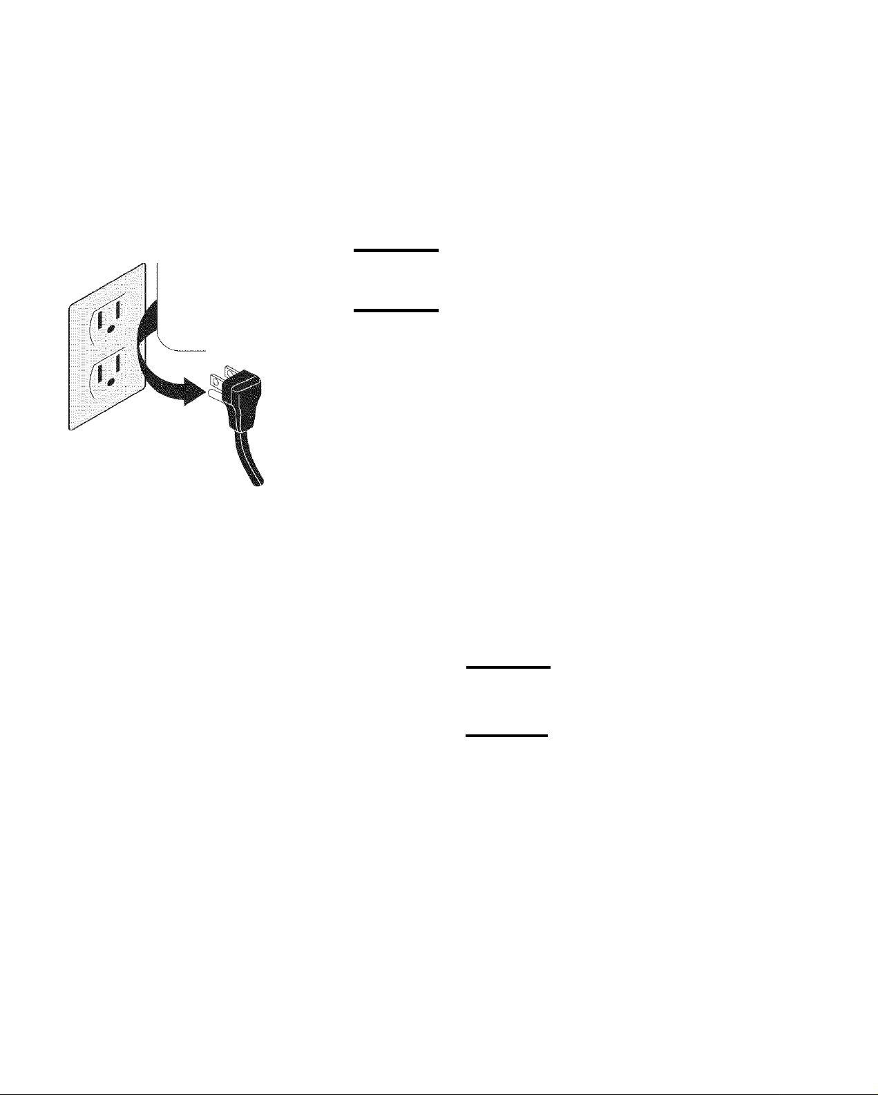
Grounding type
wall receptacle
Do not, under any
circumstance, cut,
remove, or bypass
the grounding prong.
Power supply cord
with 3-prong
grounding plug
Grounding Instructions
(electric ignition models only)
A WARNING
an extension cord, or remove grounding prong from electrical power cord.
Failure to follow this warning can cause serious injury, fire or death.
A WARNING
your protection against shock hazard and should be plugged directly into a
properly grounded receptacle. DO NOT cut or remove the grounding prong from
this plug.
For personal safety, the range must be properly grounded. For maximum safety,
the power cord must be plugged info an electrical outlet that is correctly polarized
and properly grounded.
If a 2-prong wall receptacle is the only available outlet, it is the personal
responsibility of the consumer to have it replaced with a properly grounded 3-
prong wall receptacle installed by a qualified electrician.
See the INSTALLATION INSTRUCTIONS packaged with this range for complete
installation and grounding instructions.
Avoid fire hazard or elecfrical shock. Do not use an adapter plug,
This appliance is equipped with a 3-prong grounding plug for
Important Safety Notice
The California Safe Drinking Water and Toxic Enforcement Act requires the Governor of California to publish a list of substances
known to the state to cause cancer, birth defects or other reproductive harm, and requires businesses to warn customers of
potential exposure to such substances.
rii
32
;
M
Conversion to Liquefied Petroleum Gas (or L.P. Gas)
The natural gas range is designed to allow for conversion to
Liquefied Petroleum (L.P.) Gas.
If L.P. conversion is needed, contact 1 -800-4-MY-HOME®for
assistance. The L.P. Conversion Kit is provided with this range
and is located on the left lower REAR (back side) panel of the
range. Before installing the kit be sure to follow the L.P.
Installation Instructionscarefully.
Awarning
shock may occur if the range is not installed by a
qualified installeror electrician.
Awarning
required in order for this appliance to satisfactorily meet
the application needs must be made by Sears Service.
Personal injury or death from electrical
I Any additions, changes or conversions

PROTECTION AGREEMENTS
ACUERDOS DE PROTECCION
In the U.S.A.
Master Protection Agreements
Congratulations on making a smart purchase. Your new
Kenmore® product is designed and manufactured for years
of dependable operation. But like all products, it may require
preventive maintenance or repair from time to time. That’s
when having a Master Protection Agreement can save you
money and agg ravation.
Purchase a Master Protection Agreement now and protect
yourself from unexpected hassle and expense.
The Master Protection Agreement also helps extend the life
of your new product. Here’s what’s included in the
Agreement:
gf Expert service by our 12,000 professional repair
specialists.
gf Unlimited service and no charge for parts and labor
on all covered repairs.
0" “No-lemon” guarantee - replacement
of your covered product if four or more product failu res
occurwithin twelve months.
Й' Product replacement if your covered product can’t be
fixed.
0" Annual Preventive Maintenance Check at your
request - no extra charge.
gf Fast help by phone - phone support from a Sears
technician on products requiring in-home repair, plus
convenient repair scheduling.
0' Power surge protection against electrical damage
due to powerfluctuations.
0" Rental reimbursement if repair of your covered
product takes longer than promised.
Once you purchase the Agreement, a simple phone call is
all that it takes for you to schedule service. You can call
anytime day or night, or schedule a service appointment
online.
Sears has overt 2,000 professional repair specialists, who
have access to over 4.5 million quality parts and
accessories. That’s the kind of professionalism you can
counf on to help prolong the life of your new purchase for
years to come. Purchase your Master Protection
Agreementtoday!
Some limitations and exclusions apply.
For prices and additional information call
1-800-827-6655.
Sears Installation Service
For Sears professional installafion of home
appliances, garagedooropeners,waterheaters,
and other major home items, in the U.S.A. call
1-800-4-MY-HOME®.
En los EE.UU.
Acuerdos maestros de protección
Lo felicitamos por haber hecho una compra inteligente. Su
nuevo producto Kenmore® fue diseñado y fabricado para
ofrecer muchos años de servicio confiable. Sin embargo,
como todo producto, el mismo podría requerir mantenimiento
preventivo o reparaciones ocasionales. Es por eso que el
tener un Acuerdo maestro de protección podría ahorrarle
dinero y molestias.
Adquiera ya un Acuerdo maestro de protección y protéjase de
gastos y frustraciones inesperados.
El Acuerdo maestro de protección también ayuda a extender
la vida de su producto nuevo. El Acuerdo incluye lo siguiente:
0" Servicio profesional por nuestros 12.000 profesionales
especialistas en reparación.
0" Servicio ilimitado sin cargos adicionales por piezas
y servicio en todas las reparaciones cubiertas.
0f Garantía de “no-limón” - reemplaza su producto
cubierto si ocurren cuatro o más desperfectos en los
primeros doce meses.
0f Reemplazo del producto si el mismo no puede ser
reparado.
0f Verificación de mantenimiento preventivo anual a
su petición y sin cargos adicionales.
0f Pronta ayuda por teléfono - apoyo por teléfono por un
técnico de Sears en los productos que requieran
reparación en casa, además de la conveniencia de hacer
una cita para la reparación.
0f Protección contra picos de energía o daños
eléctricos causados por fluctuaciones de la corriente
eléctrica.
0f Reembolso del alquiler si la reparación de su producto
cubierto toma más del tiempo prometido.
Una vez que adquiera este Acuerdo, una simple llamada
telefónica es todo lo que necesita para hacer una cita de
servicio. Usted puede llamar a cualquier hora del día o de la
noche para programar una cita de servicio por Internet.
Sears cuenta con más de 12.000 profesionales especialistas
de reparación con acceso a más de 4,5 millones de piezas y
accesorios de calidad. Esa es la clase de profesionalismo
con la que puede contar para extender la vida útil de su nueva
adquisición por muchos años. ¡Adquiera su Acuerdo maestro
de protección hoy!
Algunas limitaciones y exclusiones podrían aplicarse.
Para precios e información adicional, llame al
1-800-827-6655.
Servicio de instalación Sears
Para una instalación profesional de Sears en
electrodomésticos, abridores de puertas de garaje,
calentadores de agua y otros artículos mayores del hogar,
llameal 1-888-SU-HOGAR®.
REV. 030509
Before Using Your Range
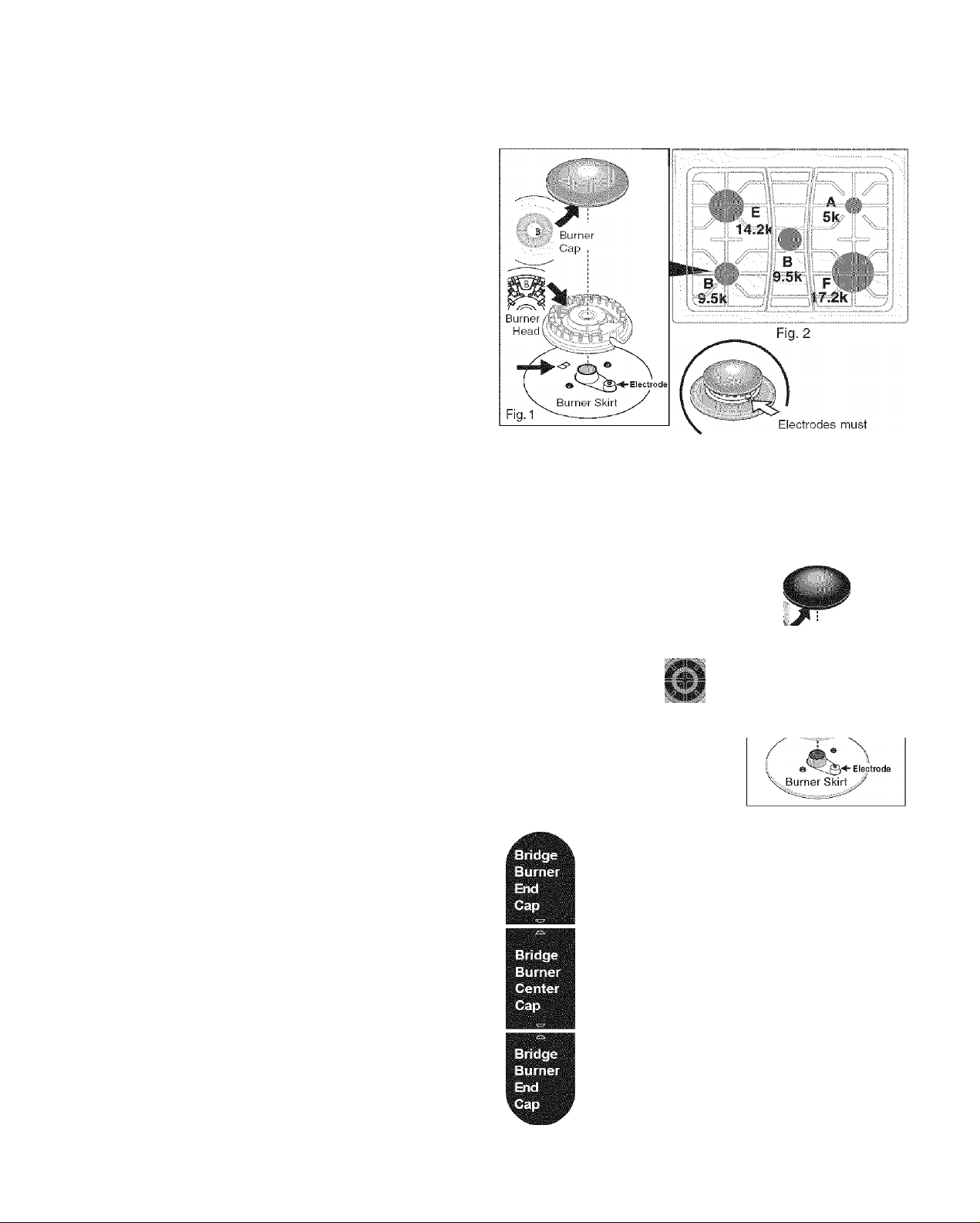
Assembly of Burner Heads & Burner Caps (for Deep Well Cooktop models only)
Your range is shipped with the Burner Heads and Burner Caps in the correct locations. Packing material is located between
the Burner Heads and the cooktop.
a. Be sure to follow the installation instructions before
installing and using your new range.
b. Remove ail packing tape from cooktop area. Remove all
Burner Caps and Burner Heads.
c. Discard all packing material located under Burner Heads.
d. To replace Burner Heads & Caps, match the letters
located under center of Burner Caps with the letters
located inside Burner Heads (Fig. 1).
e. Match the letters stamped on Burner Skirts with Burner
Heads and Burner Caps (See Fig. 1). Replace the Burner
Heads and Caps on cooktop (See Fig. 2). Carefully align
the Electrodes into slot or hole of each Burner Head (Fig.
3). Note: The Burner Heads should sit flat on Cooktop
Burner Skirts.
f. Unpack Burner Grates and position on the cooktop.
Fig. 1
Assembly of Burner Heads & Burner Caps (for Ceramic Glass Cooktop models only)
Your range is shipped with the Burner Heads and Burner Caps in the correct locations. Packing material is located between
the Burner Heads and burner skirts.
align into slot or hole for each
Fig. 3
Burner Head
a. Be sure to follow the installation instructions before
installing and using your new range.
b. Remove any packing tape from cooktop. Remove all
Burner Caps and Burner Heads, except DO NOT RE
MOVE Burner Head for Triple Ring Burner (right-front
burner position; See Fig. 4).
c. Discard any packing material located under the Burner
Heads (except Triple Ring Bumerposition).
d. Replace right rear Burner Head & Cap onto cooktop.
Match the letter for the right-rear burner located inside of
Burner Cap with the letter located inside Burner Head
(only the right-rear position is marked with letter A - See
Fig. 5). Carefully align the Electrode into slot of Simmer
Burner Head (Fig. 7).
e. CAREFULLY (DO NOT FORCE) align the Bridge Burner
Head over the 2 Bridge Burner Electrodes located on left
side of the cooktop. After placing the Bridge Burner Head
on the burner skirt, MAKE SURE that the Bridge Burner
Head lies evenly on burnerskirt.
f. Replace Bridge Burner Caps. These include 1 Bridge
Burner Center Cap (rectangular shaped) and the 2 Bridge
Burner End Caps (The Bridge Burner End Caps will fit at
either the front or rear Bridge Burner Head locations).
Make sure that the tabs located under the Bridge Burner
Caps fall into the slots located in the Bridge Burner Head
(See black arrows in Fig. 6) and that the Bridge Burner
Caps lie flat and evenly on top the Bridge Burner Head.
g. Unpack Burner Grates. Position End Burner Grates on
cooktop. Place Center Burner Grate between the end
Burner Grates and check that all the Burner Grate legs lie
fiat on the glass cooktop surface.
i?k
9k
.. 3 positrons' ' 5k a
" illiiilB''
Trillile Ring
Burner
.;k -
Fig. 4
Bridge Burner
Head
^ 1:
- 2 Electrode
hole
locations
through
Bridge
Burner
Head
Burner
Head
..i'Ai,'" Burner
Cfiu
Fig. 5
■ -.
V Electrode
must align into slot or hols
for Simmer Burner Head
Fig. 7
Fig. 6
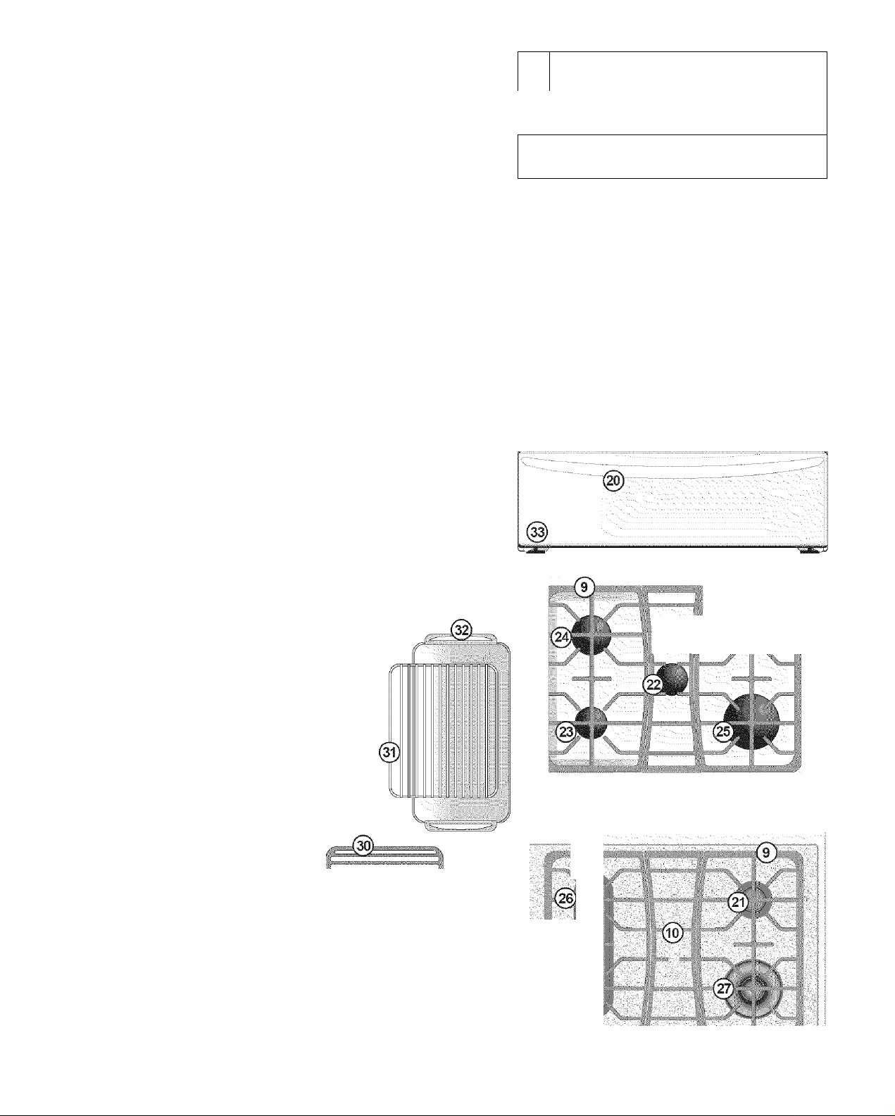
Range Features
Your Elite Gas Range Features include:
1
Electronic Oven Control with Timer.
2
Glass Touch Sensitive Control Panel.
3
Left Front Burner Valve & Knob.
4
Lett Rear Burner Valve & Knob or Bridge Burner Valve & Knob
(some models).
5
Center Burner Valve & Knob (some models).
6
Right Rear Burner Valve & Knob.
7
Right Front Burner Valve & Knob.
8
Easy to clean Deep Well Cooktop (some models) or Ceramic
Gas through Glass Cooktop (some models).
9.
Dishwasher safe Burner Grates (colors vary).
10
Dishwasher safe Cenfer Burner Grate (colors vary).
11
Warmer Drawer Control & Indicator Light.
12
Self-Clean Oven Door Lafch.
13
Automatic Oven Door Light Switch.
14
Dual Oven Interior Lights with Shields.
15
Self-Cleaning Oven interior.
16
Convection Bake Fan & Cover.
17
Adjustable Porcelain Coated Oven Racks (includes Handle &
Half Oven Racks).
18
Large 1 piece Oven Door Handle (styles & colors vary with
model).
19
Full width Oven Door (styles & colors vary with model).
20
Warmer Drawer with Handle & Warmer Drawer Rack.
21
5.000 BTU Simmer Burner.
22
9.500 BTU Center Burner (some models).
23
9.500 BTU Power Burner (some models).
24
14.200 BTU Power Burner (some models).
25
17.200 BTU Power Burner (some models).
26
*9,000 BTU Burners (Bridge Burner with all 3 burners combined
is 27,000 BTU) (some models).
3.000 to 16,000 BTU Triple Ring Burner
(some models)
28
Broil Pan.
29
Broil Pan Insert.
30
Searing Grill.
31
Roasting Rack.
32
Griddle.
33
Leveling Legs and Anti-tip Bracket
(included).
- ■ - .
®
0@
(©
(gD..Q0:.:.,00,(gQ^,o©.
(I-;)
15)
(19
i.4
________________
>
(ii
NOTES: The featu res of your range
may vary according to model type &
color.
‘Bridge Burnerfeatured on Glass
Cooktop models only.
(.29)
(23)
Deep Well Cooktop style
;Э )
Я
©
*Ceramic Glass Cooktop style
Before Setting Oven Controls
■1
OVEN VENT
■
Fig. 2
e
o
m
e
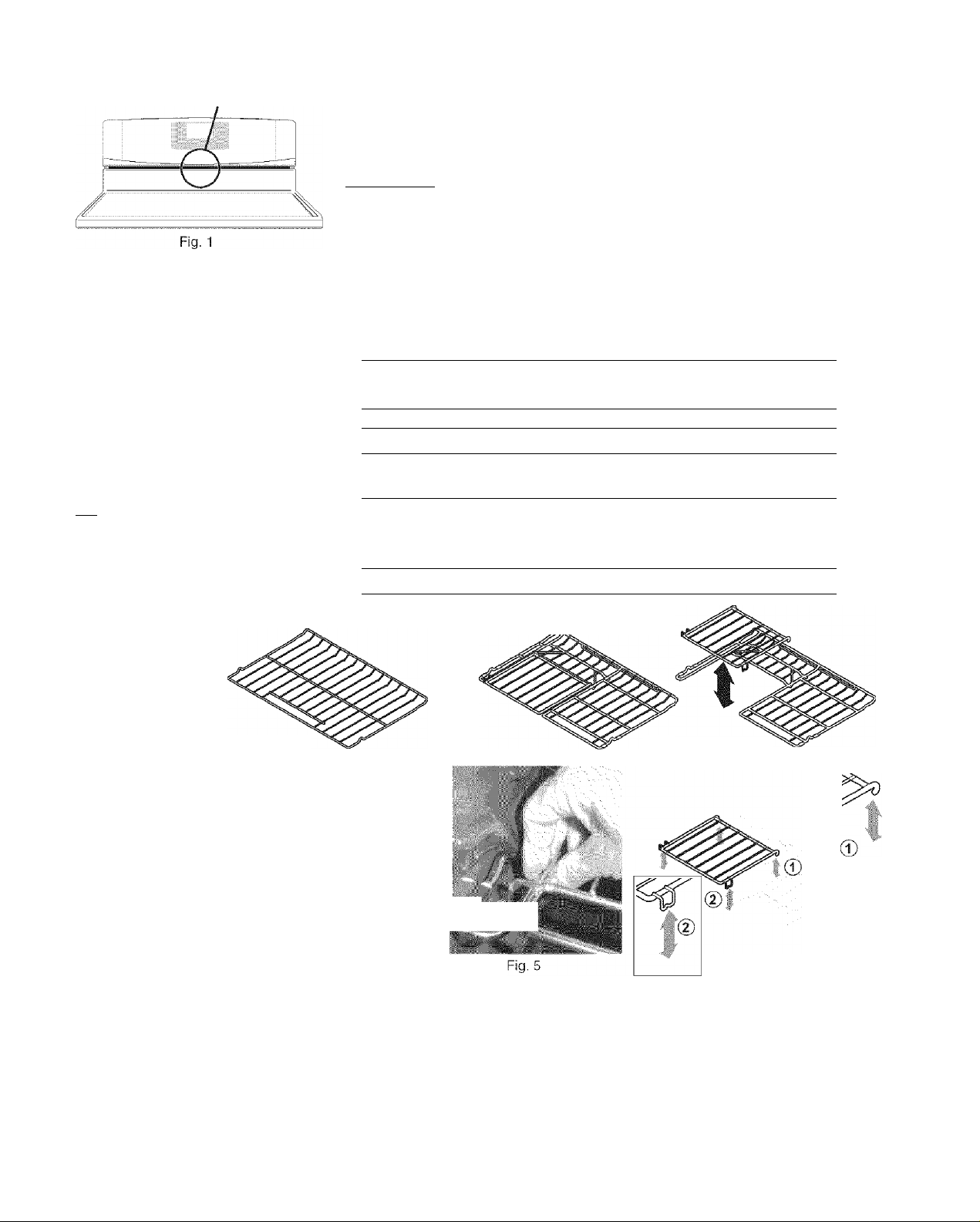
Oven Vent Location
The oven vent is located below the backguard (See Fig. 1). When the oven is on,
warm airis released through this vent. This venting is necessary for proper air
circulation in the oven and good baking results. DO NOT BLOCK THE VENT.
iàCAUTION
Wait until the oven has completely cooled if possible. Oven racks may be HOT and
may cause burns.
I
Always use pot holders or oven mitts when adjusting the oven racks.
Removing & Replacing Oven Racks
To remove, pull the rack forward until It stops. Lift up front of rack and slide out.
To replace, fit the rack onto the guides on the oven walls. Tilt the front of the rack
upward and slide the rack back into place.This range has a total of 6 oven rack
postions.
Recommended Rack Positions for Broiling, Baking & Roasting:
Food Rack Position
Broiling hamburgers & steaks 5
Broiling meats, chicken or fish 5, 4or3
Cookies, cakes, pies, biscuits
& Muffins
Frozen pies, angel food cake,
-
yeast, bread, casseroles, small
cuts of meat or poultry
Turkey, roast or ham 1 or Roasting Rack
2 or3
1 or Roasting Rack
rii
¥
T ■
m
Types of Oven Racks
Flat Handle Oven Rack
Fig. 3
Your range may be equipped with one or more
of the oven rack types shown; a Porcelain
coated Flat Handle Oven Rack (Fig. 3) ora
Porcelain coated Flat Oven Half Rack (Fig.
4). The Flat Oven Half Rack has a removable
insert that can provide extra space for larger
food items. The right half rack portion may still
be used for other food items like a casserole
dish (See Fig. 4).
To remove the Half Oven Rack insert, squeeze on the left front insert side (See Fig. 5) of the rack and tilt out clockwise . To
reinstall insert rear hooks at back of insert (See 1 -Fig. 6) and lay insert down. Make sure both insert front hooks snap into
rack (See 2-Fig. 6).
^mmi
Flat Half Oven Rack
Fig. 4
Fig. 6
Do not use cookware that extends beyond the edge of the Oven Fiat Half Rack. For best results, allow 2 inches between
the pan placed on the rack and oven side or rear walls.
Before Setting Oven Controls
Baking Layer Cakes with 1 or 2 Oven Racks
For best results when baking cakes using 2 oven racks, place cookware on oven rack positions 2 & 5 (See Fig. 1 and Fig.
2 on page 9). For best results when using a single oven rack, place cookware on oven rack position 4 (See Fig. 2 and Fig.
2 on page page 9).
Air Circulation in the Oven
For best air circulation and baking
results allow 2-4" (5-10 cm) around
the cookware for properaircirculation
and be sure pans and cookware do not
touch each other, the oven door, sides
or back of the oven cavity. The hot air
must be able to circulate around the
pans and cookware in the oven for
even heat to reach around the food.
...............
Fig. 1
Fig.2
Before Setting Surface Controls
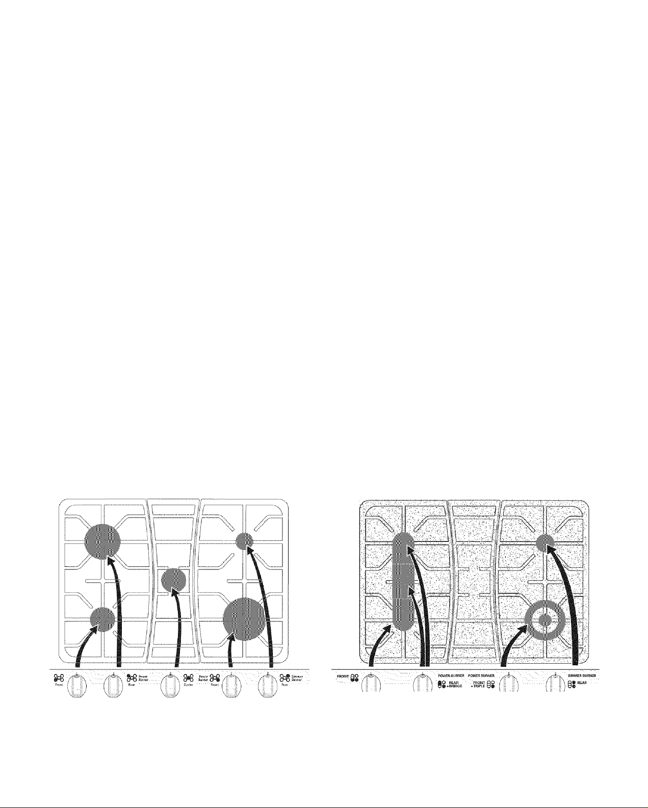
Control Locations of the Gas Surface Burners
(For models with a Deep Well Cooktop-See Fig. 3)
Ther SIMMER Burner is best used for simmering delicate
sauces, etc. This burner is located at the right rear burner
position on the cooktop.
The STANDARD Burners can be used for most surface
cooking needs. These burners are located at the left front
and center positions on the cooktop.
The POWER Burners are best used for bringing large
quantities of liquid rapidly up to temperature or when
preparing larger quantities of food. These burner are
located at the right front and left rear positions on the
cooktop.
(For models with a Ceramic Cooktop-See Fig. 4)
Ther SIMMER Burner is best used for simmering delicate sauces,
etc. This burner is located at the right rear burner position on the
cooktop.
The POWER Burner is best used for bringing large quantities of
liquid rapidly up to temperature or when preparing larger quantities
of food. This burner is located at the right front position on the
cooktop.
The BRIDGE Burner is best suited when using rectangular or long
shaped cookware. The left rear and left middle positions are
combined. The left front Burner may also be added for a total of 3
burners.
The TRIPLE RING Burner offers a complete range of gas surface
burner settings from simmering to the output of a Power Burner at
one iocation.
o„o
9P0
Front
Left Left
Front Rear
Burner Burner
Rear
Power
Burner
Fig. 3
Center
Center
Burner
Power
Burner 0^0
Front
Right Right
Front Rear
Burner Burner
0^0 Burner
Rear
Simmer
10
FRONT go
Left
Front
Burner
POWER BURNER
REAR
flO
BRIDGE
0 ® +
Left Rear &
Bridge Burner
Fig. 4
POWER BURNER
FRONT PO
+ TRIPLE U#
Right
Front
Burner
SIMMER BURNER
• REAR
#
§
Right
Rear
Burner

Surface Cooking
• Operating Gas Surface Burners
• Setting Proper Burner Flame Size
• Operating Triple Ring Burner
^CAUTION
top of the range when it is in use. These items could melt or ignite. Potholders, towels or wood spoons could catch
if placed too close to a flame.
Do not place plastic items such as salt and pepper shakers, spoon holders or plastic wrappings on
Operating the Gas Surface Burners:
1. Place cooking utensil on surface burner.
2. Push the knob in and turn counterclockwise out of the OFF position (See Fig. 1).
3. Release the knob and rotate to the LITE position. Note: All four electronic surface ignitors will
spark at the same time. However, only the burner you are turning on will ignite.
4. Visually check that the burner has lit.
5. Push the control knob in and turn counterclockwise to the desired flame size. The control
knobs do not have to be set at a particular setting. Use the guides and adjust the flame as
needed. DO NOT cook with the surface control knob in the LITE position (The electronic ignitor
will continue to spark if the knob is left in the LITE position).
Setting Proper Surface Burner Flame Size
The size and type of utensil used and the amount of food being cooked will
influence the setting needed for cooking.
Flame Size Type of Cooking
High Flame j Start most foods; bring water to a boil; pan broiling.
Medium Flame S Maintain a slow boil; thicken sauces, gravies; steaming.
Low Flame ? Keep foods cooking; poach; stewing.
Always select cookware that is suitable for the amount and type of food being prepared.
Select a burner and flame size appropriate to the pan. Never allow flames to extend beyond
the outer edge of the pan.
flame size
Improper
flame size
Fig. 2
fire
Fig. 1
"‘‘W
(Л
Triple Ring Burner (some models):
The versatile Triple Ring Burner
lowest setting, only the inner ring is active, providing a low flame for any simmering needs. If needed however, two additional
gas rings may be added quickly to provide a “Power Burner” output of 16,000 BTU. When set
may be used to bring a large pan of liquid to boil quickly.
offers
a complete range of gas surface settings
from
the same burner location. At the
at
the highest, the Triple Ring
Operating the Triple Ring Burner:
1. Push the right front surface control knob
2. Release the knob and rotate to the LITE position (See Fig. 1). Note: Although all electronic surface ignitors will spark at
the same time, only the selected surface Burner will life.
3. Visually check that the inner ring of the right front Burner has lit.
4. Continue to rotate the gas control knob clockwise past the
5. Visually check that both the inner and outer ring of the Triple Ring Burner are lit.
6. When both burners are lit, continue to turn the control knob counterclockwise to adjust to the desired
both burners together. Note: The markings between the 2nd HI and LO settings on the left rear control knob
flame size for both burners. Use
needed (Referto Fig. 3).
Inner Ring
LITE
postion
Off
Fig. 3 - Triple Ring Burner Surface Control Knob markings
the guide
Inner Ring
adjustment
Hi
in
and turn counterclockwise out of
first
LO setting to the arrow marked
marks between the 2nd HI and LO settings and adjust the flame size
flame
area ■
Lo
Entire
Burner
LITE
position
—!
------
Triple
Entire Triple
Burner
flame
. adjustment
- area _L
Lo
the
OFF position (See Fig. 1).
TRIPLE,
Fig. 4
11
flame
size for
adjust
as
■ V' s.
Fig. 5
the
Surface Cooking
• Operating Triple Ring BurnerCont’d (some models)
• Operating the Bridge Burner (some models)
Operating the Triple Ring Burner at the lowest setting:
1. Push the right front surface control knob in and turn counterclockwise out of the OFF position (See Fig. 1).
2. Release the knob and rotate to the LITE position (See Fig. 1). Note: Although all electronic surface ignitors will spark at
the same time, only the selected surface Burner will life.
3. Visually check that the inner ring of the right front Burner has lit.
4. Continue to turn the control knob counterclockwise and stop at the first LO position. (Refer to Fig. 3). If a higher setting
is need adjust accordingly.
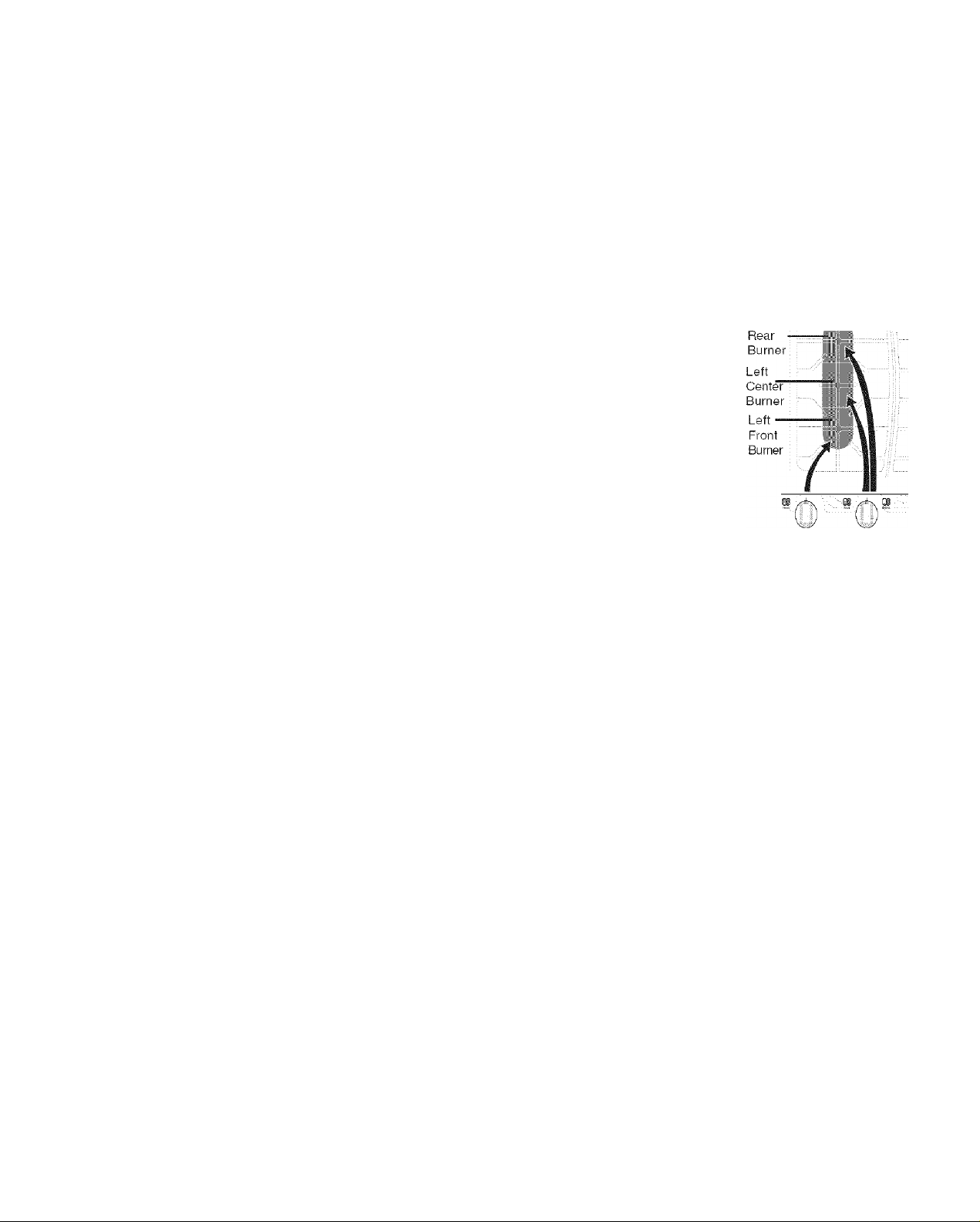
Setting the Bridge Burner (for Bridge Burner models only):
The Bridge Burner should be used with rectangular shaped cookware. Cookware like the castiron Griddle that is supplied with your range is designed specifically for best results with the
Bridge Burner.
The Bridge Burner feature may be used to combine the cooking power of 2 or if needed 3 gas
surface Burners located along the left-hand side of the glass cooktop.The left rear and left center
Burners are controlled by the left rear surface Control Knob. In addition the left front Burner may
be added to the Bridge Burner with the left front gas Control Knob (See Fig. 1).
Left
Operating the Bridge Burner {for Bridge Burner models only):
Push the left rear surface control knob in and turn counterclockwise out of the OFF position
(See Fig. 1).
2.
Release the knob and rotate to the LITE position (See Fig. 1 on page 11). Note: Ail electronic
surface ignitors will spark at the same time. However, only the selected surface Burnerwill
life.
3.
Visually check that the left rear Burner has lit.
4.
Confine to rotate the gas control knob clockwise past the first LO setting to the arrow marked
BRIDGE.
5.
Visually check that both the left rear and left center Burners are lit.
6.
When both burners are lit, continue to turn the control knob counterclockwise to adjust to the desired flame size for
both burners together. Note: The markings between the 2nd HI and LO settings on the left rear control knob adjust the
flame size for both burners. Use the guide marks between the 2nd HI and LO settings and adjust the flame size as
needed (Refer to Fig. 3).
Add the left front Burner if needed. Once lit, visually adjust the flame size of the left front Burner to match the flame size
of the Bridge Burner.
Place cooking utensil centered over the left-hand cooktop surface Burner Grate. DO NOT cook with any of the surface
control knobs in the LITE position (The electronic ignitor will continue to spark if the knob is left in the LITE position).
Fig. 1
«FAfi BK1ÜI5E
Left Rear Left Rear
Burner Burner
LfTE flame
position [-adjustment
___I__
Off
Fig. 3 - Left Rear Bridge Burner Surface Control Knob markings
Note: If only the left rear surface Burner is needed, follow the instructions provided below.
L area
Hi
Bridge
Burner
LITE
position
—I—
Lo Bridge Hi
f
Bridge
Burner
flame
adjustment
area
_____
L
Lo
Operating only the Left rear Gas Surface Burner (for models equipped with Bridge Burner):
1. Place cooking utensil centered over the left-rear surface Burner Grate.
2. Push the left rear surface control knob in and turn counterclockwise out of the OFF position (See Fig. 2).
3. Release the knob and rotate to the LITE position. Note: Although all electronic surface ignitors will spark at the same
time, only the left rear Burner will ignite.
4. Visually check that the I eft-rear burner has lit. Adjust the flame size by turning the control knob between the first HI
and LO settings (See Fig. 3). DO NOT cook with the surface control knob in the LITE position (The electronic ignitor
will continue to spark if the knob is left in the LITE position).
12
Surface Cooking
• Care & Seasoning of the Griddle
• Using the Griddle
Care & Seasoning of the Griddle
Before first use:
» Wash Griddle in hot soapy water. Rinse and then dry completely.
® Apply a thin coat of vegetable oil to the entire surface (front and back of griddle).
® Preheat your oven to 350°F . Place the griddle on the upper rack in your oven.
• Bake griddle for 1 hour at 350°F, then turn oven OFF and let cool before removing.
» The surface may appear to have a tacky feel to it from the seasoning process. If
desired, wash the griddle in hot soapy water, rinse well, and dry completely.
After each use:
® To prevent rusting, store in a dry place and keep uncovered.
• After each use, clean with a stiff brush and hot water only.
• DO NOT CLEAN GRIDDLE IN DISHWASHER.
® Dry Immediately and apply a light coating of vegetable oil to griddle before storing.
Using the Griddle:
• Place either side of the griddle centered over the left side gas burners or over the
Bridge Burner (some models). For location refer to Fig. 1.
» Preheat the griddle for 5 minutes on medium to medium low setting. Slow
preheat ensures even heat distribution during the cooking process.
® DO NOT preheat the griddle on HI setting. Preheating on HI may warp the griddle
and prevent even heat distribution.
Fig. 1
rn
:
i"
.C
Setting Warmer Drawer Controls
• Arranging Warmer Drawer Racks
• Using the Warmer Drawer
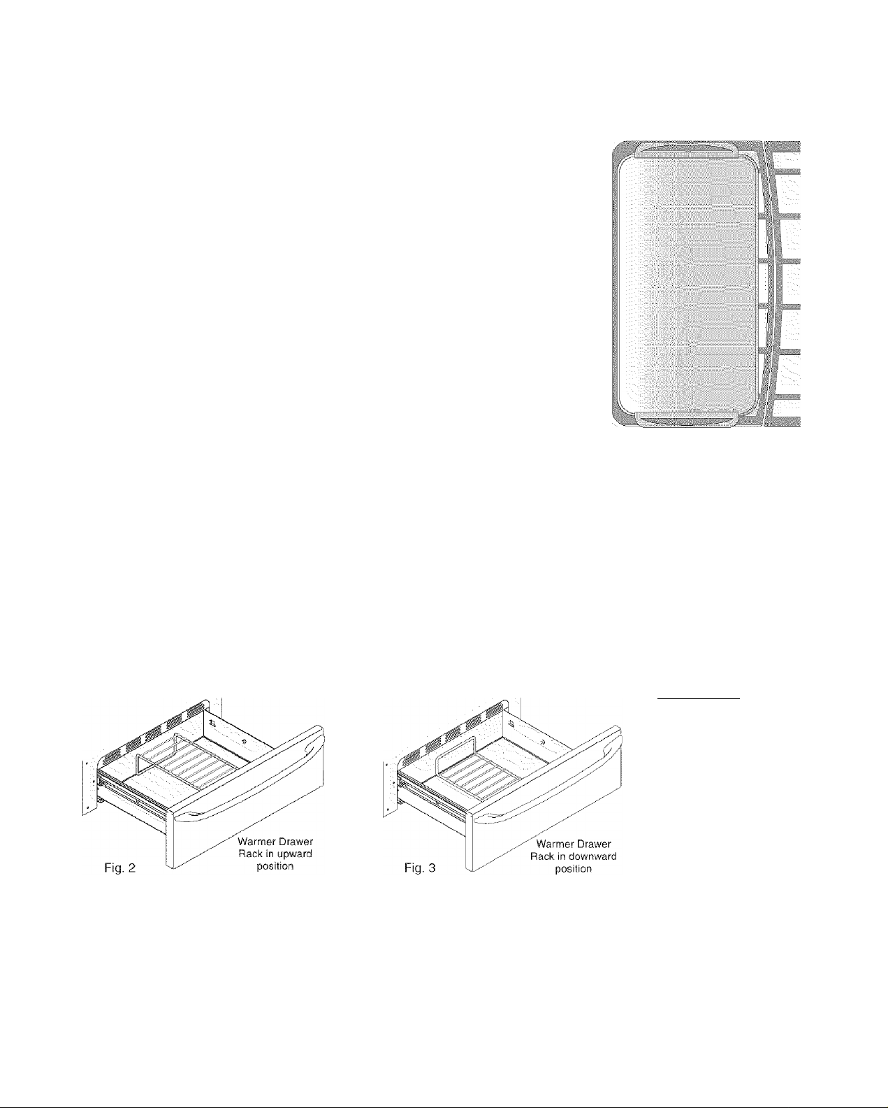
Arranging Warmer {Warm & Ready™) Drawer Rack Positions
The rack can be used in two ways:
» In the upward position (Fig. 2) to allow low profile food items to be placed both under and on top of the rack (for
example, rolls or biscuits on top of the rack and a casserole dish underneath).
• In the downward position (Fig. 3) to allow you to place light weight food items and empty dishware (for example, rolls
or pastries and dinner plates) on the rack.
Acaution
potholdersoroven mitts
when removing food from
the Warmer Drawer as
cookware and plates will
be hot and you can be
burned.
Using the Warmer Drawer
The purpose of the Warmer Drawer is to keep hot cooked foods at serving temperature. Always start with hot food. It is not
recommended to heat cold food in the Warmer Drawer. All food placed in the Warmer Drawer should be covered with a lid
or aluminum foil to maintain quality.
Always use
Do not use plastic wrap to cover food. Plastic may melt onto the drawer and be very difficult to clean. Use only utensils and cookware recommended for oven use in the Warmer Drawer.
Note: The Warmer Drawer will not operate during the Self-Clean cycle.
13

Setting Warmer Drawer Controls
• Warmer Drawers Bread Proofing Indicator Lights
• Setting Warmer Drawer & Bread Proofing Controls
» Warmer Drawer Food Temperature Settings
Warmer (Warm & Ready™) Drawer & Bread Proofing Indicator Lights
The control and indicator lights for the Warmer Drawer and Bread Proofing features are located on the control panel. The
indicator lights will turn ON when the control is set, and remain ON until the controls are turned OFF.
To Set the Warmer Drawer & Bread Proofing Controls:
1. Touch the
Drawer indicator light will flash. Note: If no further pads are touched within 25
seconds the request to power the Warmer Drawer ON will clear.
2.
Set the desired power level. Touch once to turn ON the power level for HI
(Fig. 2) or to
indicator light will glow steady indicating the Warmer Drawer is ON.
3.
Each touch of the or pads will decrease or increase through 6
power levels from HI (Fig. 2) to MED (Fig. 3) to LO (Fig. 4) and to the Bread
Proofing feature (Fig. 5). if the Warmer Drawer is set at the LO setting and the
pad is touched again the Bread Proofing feature will be turned ON (The
Bread Proof indicator light will glow steady indicating the Bread Proofing feature
in ON (See Fig. 5 & bread dough preparation instructions on this page). To return
to standard Warmer Drawer settings touch pad at least once. Note: For
best results, preheat the Warmer Drawer before adding the food or bread dough.
An empty drawer will preheat in approximately 15 minutes.
4.
When the food ordough is ready for removal, touch the pad once to turn
the Warmer Drawer or Bread Proof feature OFF. The Warmer Drawerindicator
light will turn OFF.
Warmer Drawer Food Temperature Settings
Usethe recommended Warmer Drawer
food temperature settings table (See Fig.
6). If a particular food is not listed, start
with the MED setting. If more crispness is
desired, remove the lid oraluminum toil
from the food.
Most foods can be kept at serving
temperatures on the MED setting. When a
combination of foods are to be kept warm
(for instance, a meat with 2 vegetables and
rolls), use the HI setting. To avoid heat
loss, do not open the Warmer Drawer
repeatedly while in use.
pad at the Warmer Drawer control position. The Warmer
turn
ON the power level for LO (Fig. 4). The Warmer Drawer
Warmer Drawer Recommended
Food Settings Table
Food Item Setting
Bacon HI
Hamburger Patties HI
Poultry HI
Pork Chops HI
Fried Foods HI
Pizza HI
Gravies MED
Casseroles MED
Eggs MED
Roasts (Beef, Pork, Lamb) MED
Vegetables MED
Biscuits MED
Rolls, hard MED
Pastries MED
Rolls (soft) LO
Empty Dinner Plates LO
..
Warmer
Drawer
Fig. 1
Hi r'»
Med
fs
Proof i
Bread j Bread
Lo iï"
. . .. . . . .
Fig.
2 :
•
i
Hi* Hi*
m
Med *
Lo
Fig. 4
Proof Î
Bread j
m
!
, “
»Hi
...'A
Med
Lo
Med ..
Lo
Med *
Lo
Proof
Bread
Hi*
m
Fig. 3
•
Fig. 5
Proof
•
Proof
Bread
14
Fig. 6
 Loading...