

Kenmore 79079019100, 79079014100, 79079012100, 79079013100 Installation Guide
INSTALLATION AND SERVICE MUST BE PERFORMED BY A QUALIFIED INSTALLER.
IMPORTANT: SAVE FOR LOCAL ELECTRICAL INSPECTOR'S USE.
READ AND SAVE THESE INSTRUCTIONS FOR FUTURE REFERENCE.
/
If the information in this manual is not followed /
exactly, a fire or explosion may result causing property
damage, personal injury or death.
FOR YOUR SAFETY:
-- Do not store or use gasoline or other flammable vapors
and liquids in the vicinity of this or any other appliance.
WHAT TO DO IF YOU SMELL GAS:
• Do not try to light any appliance.
• Do not touch any electrical switch; do not use any phone
in your building.
• Immediately call your gas supplier from a neighbor's
phone. Follow the gas supplier's instructions.
• If you cannot reach your gas supplier, call the fire
department.
-- Installation and service must be performed by a qualified
installer, service agency or the gas supplier.
1
A
• ALL RANGES
CAN TiP
• INJURYTO PERSONS
COULD RESULT
• INSTALL ANTI-TIp
DEVICE PACKED WITH
RANGE
• SEE INSTALLATION
V
INSTRUCTIONS
VIEW
s,oEf
I÷1
47-3/4"
Range 3"
T
36"
Door Open _\\ 29 7/8"_ _"
_-_ 30" _ 0' Clearance Below Cooking Top and at Rear of Range.
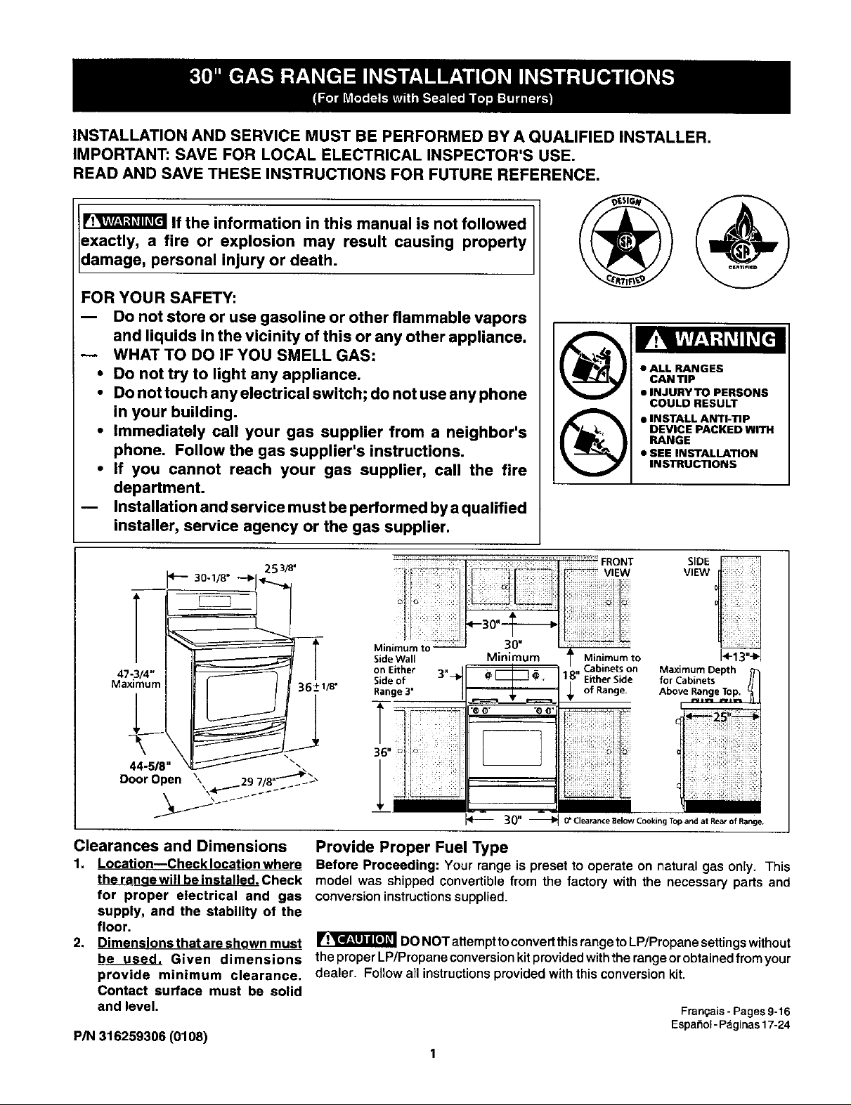
Clearances and Dimensions
1, Location--Check location where
_ewillbein tI_.Check model was shipped convertible from the factory with the necessary parts and
for proper electrical and gas conversioninstructionssupplied.
supply, and the stability of the
floor.
2.
Dimensions that are shown must _ DONOTattempttoconvert thisrangetoLP/Propanesettingswithout
be used. Given dimensions theproperLP/Propaneconversionkitprovidedwiththersngeorobtainedfromyour
provide minimum clearance, dealer. Followall instructionsprovidedwiththisconversionkit.
Contact surface must be solid
and level. Fran_ais- Pages9-16
P/N 316259306 (0108)
Provide Proper Fuel Type
Before Proceeding: Your range is presetto operate on natural gas only. This
Maximum Depth
for Cabinets
Above Range Top.
Espa_ol- P_ginas 17-24
Important Notes to the Installer
1. Read all instructionscontained in these installation
instructionsbeforeinstallingrange.
2, Removeallpackingmaterialfromtheovencompartments
before connectingthe gas and electrical supplytothe
range.
3. Observe all governing codes and ordinances.
4. Be sure to leave these instructions with the consumer.
Never leave children alone or unattended
in the area where an appliance is in use. Aschildrengrow,
teachthem theproper,safeuseofallappliances.Neverleave
theoven dooropenwhenthe range isunattended.
Stepping, leaningor sitting on the doors or
drawers of this range can result In serious injuries and
can also cause damage to the range.
Important Note to the Consumer
1, Keepthese instructionswithyour Use & Care Guidefor
futurereference.
IMPORTANT
SAFETY INSTRUCTIONS
Installationofthis rangemustconformwithlocalcodesor, in
the absenceoflocalcodes,withthe NationalFuel Gas Code
ANSI Z223.1--1atest edition when installed in the United
States.
When installedina manufactured (mobile)home, installation
mustconform withthe Manufactu red Home Construction and
Safety Standard, Title 24 CFR, Part 3280 [formerly the
Federal Standard for Mobile Home Construction and Safety,
Title 24, HUD (Part 280)] or, when such standard is not
applicable, the Standardfor Manufactured Home Installations,
ANSI/NCSBCS A225.1, or with local codes.
Thisrange hasbeen design certified by CSA International. As
with any appliance using gas and generating heat, there are
certain safety precautions you should follow. You will find
them inthe Use & Care Gui_, read it carefully.
Besureyour range IsInstalled and grounded properly
by a qualified Installer or service technician.
This range must be electrically grounded In
accordance wlth local codes or, In their absence,
with theNational Electrical CodeANSI/NFPA No .70--
latest edition when Installed in the United States.
See Grounding Instructions on page 5.
Before Installing the range in an area covered with
linoleum or any other synthetic floor covering, make
sure the floor covering can withstand heat at least
90°F above room temperature without shrinking,
warping or discoloring. Do not installthe range over
carpetingunlessyouplace an insulatingpadorsheetof
1/4-inch thickplywood between the range and carpeting.
Make sure the wall coverings around the range can
withstand the heat generated by the range.
Do not obstruct the flow of combustion air at the
oven vent nor around the base or beneath the lower
front panel of the range. Avoid touching the vent
openings or nearby surfaces as they may become hot
whilethe ovenis inoperation. This range requires freshair
for proper burner combustion.
• Do not store Items of interest to children in the
cabinets above the range. Childrencouldbeseriously
burnedclimbingon the range to reach items.
• To eliminate the need to reach over the surface
burners, cabinet storage space above the burners
should be avoided.
Adjust surface burner flame size so it does not
extend beyond the edge of the cooking utensil.
Excessiveflame is hazardous.
• Donot use the oven asa storage space. This creates
a potentiallyhazardoussituation.
• Never use your range for warming or heating the
room. Prolonged use of the range without adequate
ventilationcan bedangerous.
• Do not store or use gasoline or other flammable
vapors and liquids near this or any other appliance.
Explosionsor fires couldresult.
• Reset all controls to the "off" position after using a
programmable timing operation.
FOR MODELS WITH SELF-CLEAN FEATURE:
• Remove broiler pan, food and other utensils before
self-cleaning theoven. Wipe upexcessspillage,Follow
the cleaning instructionsin the Use & Care Guide.
• Unlike the standard gas range, THIS COOKTOP IS
NOT REMOVABLE. Do not attempt to remove the
cooktop.
DO NOT MAKE ANY AI-FEMPT TO
OPERATE TH E ELECTRIC IGNITION OVEN DURING AN
ELECTRICAL POWER FAILURE. RESET ALL OVEN
CONTROLS TO "OFF" IN THE EVENT OF A POWER
FAILURE.
The electric ignitor will automatically re-ignite the oven
burner when power resumes if the oven thermostat control
was left in the "ON" position.
When an electrical power failure occurs during use, the
surface burners will continue to operate.
During a power outage, the surface burners can be lit with
a match. Holda lighted match to the burner, then slowly turn
the knob to the LITE position. Use extreme caution when
lighting burners this way.
2
Before Starting
Tools You Will Need
For leveling legs and Anti-Tip Bracket:
• Adjustablewrench or channel lockpliers
• 5/16"Nutdriveror Flat Head Screw Driver
ElectricDrill&1/8" DiameterDrillBit(5/32"MasonryDrill
Bit ifinstallinginconcrete)
For gas supply connection:
• Pipe wrench
For burner flame adjustment:
Phillipshead _ and
blade-type screwdrivers
For gas conversion (LP/Propane or Natural):
• Open endwrench- 1/2"
Additional Materials You Will Need
F_
• Gas line shut-offvalve
• Pipejoint sealant that resists action of LP/Propane gas
A new flexible metal appliance conduit (1/2" NPT x 3/4"
or 1/2"1.D.)must be design certified byCSA International.
Because solid pipe restricts moving the range we
recommend using a new flexible conduit (4 to 5 foot
length) for each new installation and additional
reinstallations.
A.
Locatethe Bracket Using theTemplate- (Bracketmay
belocatedoneithertheleftorrightsideoftherange, Use
the informationbelowto locate the bracketiftemplateis
notavailable). Mark the floor or wall where left or right
sideoftherangewillbe located. Ifrearofrangeisagainst
thewallornofurtherthan1-1/4"fromwallwheninstalled,
you may usethe wall orfloor mount method. If molding
is installed and does not allow the bracket to fit flush
againstthe wall,removemoldingormountbrackettothe
floor. For wall mount,locatethe bracket by placingthe
backedge ofthe template againstthe rear wall and the
sideedgeoftemplate onthe mark madereferencingthe
sideofthe range.Place bracket ontop of templateand
marklocationofthe screw holesin wall. If rearofrange
isfurtherthan 1-1/4"fromthewallwhen installed,attach
brackettothe floor. Forfloor mount,locate the bracket
byplacingback edge ofthe template where the rear of
the range willbe located. Mark thelocation ofthe screw
holes,shownintemplate.
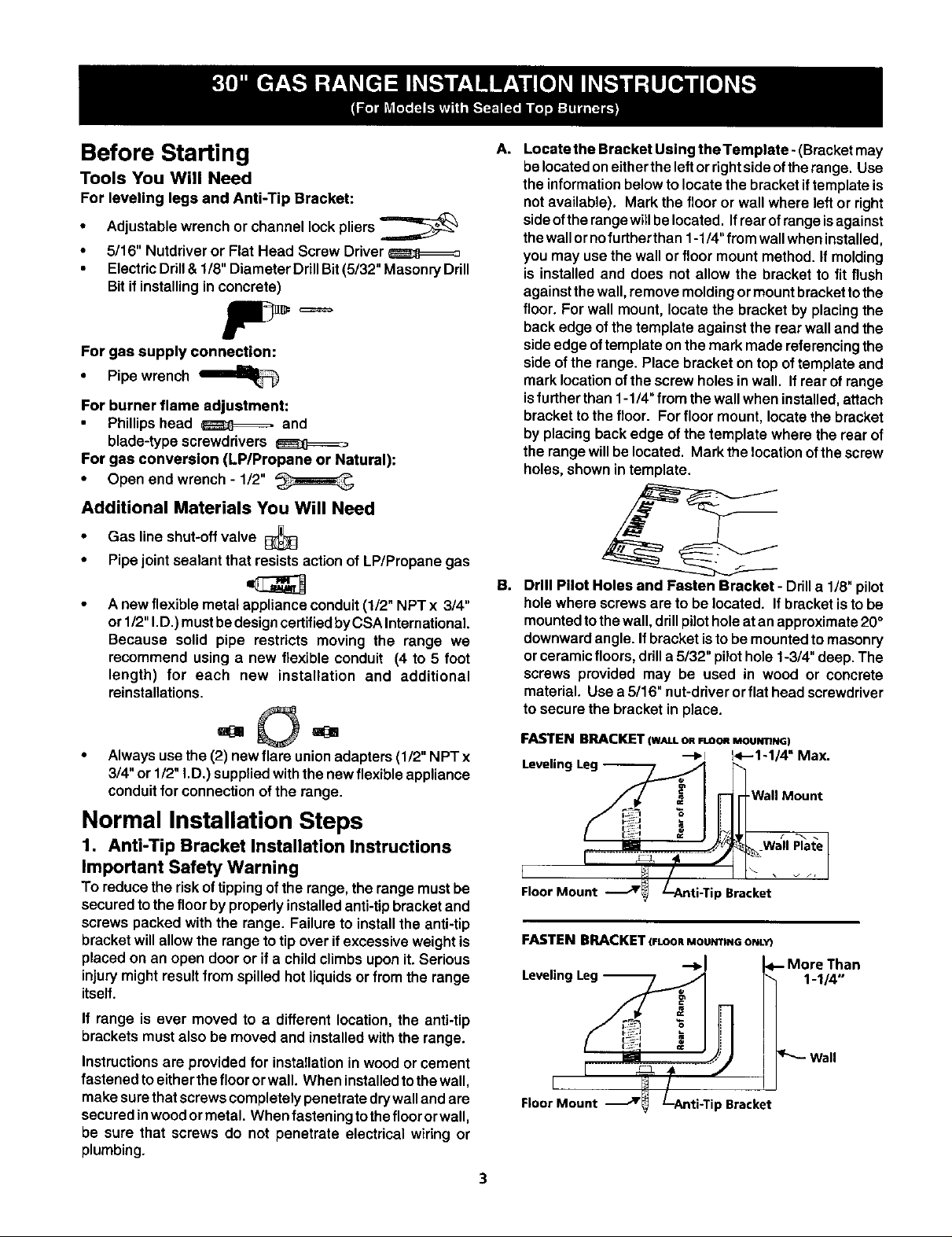
B,
Drill Pilot Holes and Fasten Bracket - Drilla 1/8"pilot
holewhere screwsare tobe located. Ifbracket isto be
mountedtothe wall,drillpilotholeatanapproximate20°
downwardangle. Ifbracketisto bemountedto masonry
orceramicfloors,drilla 5/32" pilothole 1-3/4" deep.The
screws provided may be used in wood or concrete
material. Use a 5/16" nut-driverorflat head screwdriver
to secure the bracket in place.
• Always use the (2) new flare union adapters (1/2" NPT x
3/4" or 1/2" i.D.) supplied with the new flexible appliance
conduit for connection of the range.
Normal Installation Steps
1. Anti-Tip Bracket Installation Instructions
Important Safety Warning
To reducethe riskoftippingofthe range,the rangemust be
securedtothe floorbyproperlyinstalledanti-tipbracketand
screws packed with the range. Failure to installthe anti-tip
bracketwillallowthe rangetotip over if excessive weightis
placedon an open door or if a childclimbs uponit.Serious
injurymight resultfrom spilled hotliquidsorfrom the range
itself.
If range is ever moved to a different location, the anti-tip
brackets must also be moved and installed with the range.
Instructionsare provided for installationin wood or cement
fastened to either the floor orwall. When installed to the wall,
make sure that screws completely penetrate drywall and are
secured inwood or metal. When fastening to thefloor or wall,
be sure that screws do not penetrate electrical wiring or
plumbing.
FASTENBRACKET(W_LLORROOnMou_mNG)
---I,.I 14---1-1/4"Max.
Leveling Leg _
Floor Mount ._r_ /--Anti-Tip Bracket
FASTEN BRACKET(FLOORMOUmtNOONLY)
Leveling Leg l_ 1-1/4"
[ _ 4-
Floor Mount _ !--Anti-Tip Bracket
3
I_-- More Than
H
Wall
 Loading...