

Kenmore 79071314700, 79071329701, 79071329702, 79071329703, 79071323701 Installation Guide
...
iNSTALLATiON AND SERVICE MUST BE PERFORMED BY
A QUALiFiED iNSTALLER.
iMPORTANT: SAVE FOR LOCAL ELECTRICAL INSPECTOR'S USE.
READ AND SAVE THESE iNSTRUCTiONS FOR FUTURE REFERENCE.
This conversion kit must be installed by a qualified service technician in accordance with the
manufacturer's instructions and all applicable codes and requirements of the authority having jurisdiction. Failure
to follow instructions may result in fire, explosion or production of carbon monoxide causing property damage,
personal injury or loss of life. The qualified service agency is responsible for the proper installation ofthis kit. The
installation is not proper and complete until the operation of the converted appliance is checked as specified inthe
manufacturer's instructions supplied with this kit.
Before proceeding with the conversion, shut off the gas supply before disconnecting electrical power
to the range. Be sure both power supplies are off before installing the conversion kit. Failure to do so could cause
serious bodily injury.
Note: When surface burners are converted from Natural to L.P. the BTU ratings become:
5,000 BTU* Natural Gas to 4,500 BTU* L.P. Gas
9,500 BTU* Natural Gas to 8,000 BTU* L.P. Gas
14,200 BTU* Natural Gas to 11,000 BTU* L.P. Gas
L.P. Kit Contents Kit pin 316467203 (light green label)
Part Description Part Number Qty.
Surface Burner Orifice marked 0.68mm 4,500 BTU* (blue)
Surface Burner Orifice marked 0.89mm 8,000 BTU* (no color)
Surface Burner Orifice marked 1.01 mm 11,000 BTU* (red)
L.P. Kit Installation Instructions
*Note: For operation at elevations above 2000 ft., appliance rating
shall be reduced at the rate of 4 percent for each 1000 ft. above sea
level,
How to Convert the Range for use with LP/
Propane Gas
1. Convert the Pressure Regulator
To access the gas regulator, remove the storage drawer or warmer
drawer. If equipped with a storage drawer, open & remove the drawer
completely. For models equipped with a warmer drawer, follow the
instructions below to remove the warmer drawer.
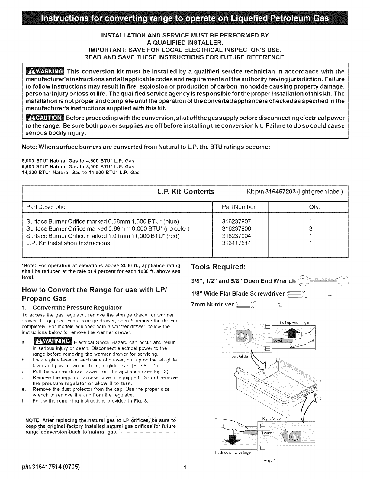
a. _ Electrical Shock Hazard can occur and result
in serious injury or death. Disconnect electrical power to the
range before removing the warmer drawer for servicing.
b. Locate glide lever on each side of drawer, pull up on the left glide
lever and push down on the right glide lever (See Fig. 1).
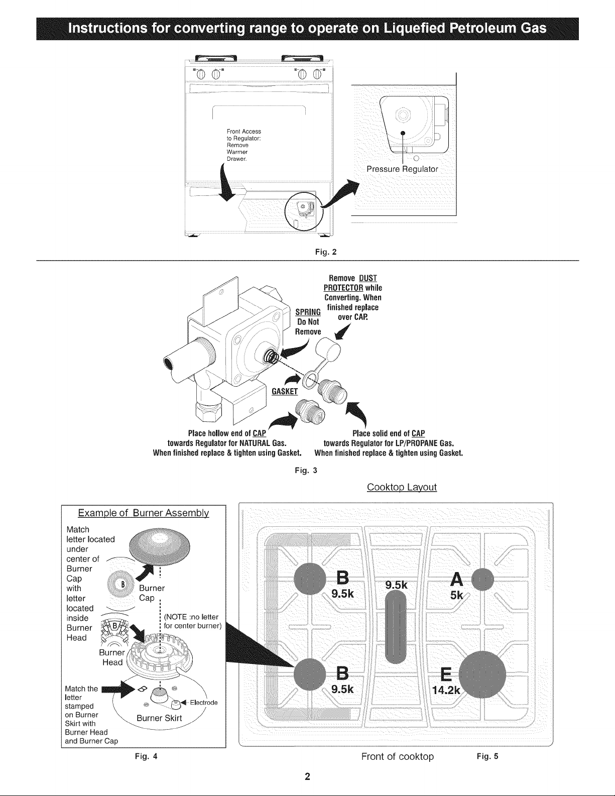
c. Pull the warmer drawer away from the appliance (See Fig. 2).
d. Remove the regulator access cover if equipped. Do not remove
the pressure regulator or allow it to turn.
e. Remove the dust protector from the cap. Use the proper size
wrench to remove the cap from the regulator.
f. Follow the remaining instructions provided in Fig. 3.
316237907
316237906
316237904
316417514
Tools Required:
3/8", 1/2" and 5/8" Open End Wrench
1/8" Wide Flat Blade Screwdriver
7mm Nutdriver
Pull up with finger
Left Glide
1
3
1
1
NOTE: After replacing the natural gasto LP orifices; be sure te
keep the original factory installed natural gas orifices for future
range conversion back to natural gas.
pin 316417514 (0705) 1
Right Glide
Push down with finger
Fig. 1
°© ©.... ©
Front Access
to Regulator:
Remove
Warmer
Drawer
SPRING
DoNot
Remove
Pressure Regulator
Fig. 2
RemoveDUST
PROTECTORwhile
Converting.When
finishedreplace
overCAP,
towardsRegulatorfor NATURALGas. towardsRegulatorforLP/PROPANEGas.
Whenfinishedreplace&tightenusingGasket, Whenfinishedreplace& tightenusingGasket.
Example of Burner Assembly
Match
located
inside
Burner
Head
Burner
Head
Match the
letter
stamped
on Burner
Skirt with
Burner Head
and Burner Cap
(NOTE :no letter
for center burner)
Burner Skirt
Fig. 4 Front of cooktop Fig. 5
PlacehollowendofCAP PlacesolidendofCAP
Fig. 3
Cooktop Layout
2

2.Convertsurfaceburnersfor LP/Propane gas:
_ Unlike the standard gas range, THiS COOKTOP IS
NOT REMOVABLE. Do not attempt to remove this cooktop.
Save the natural gas orifices removed from the appliance for possible
future conversion back to natural gas.
For all burner locations:
a. Remove burner grates & burner caps.
b. Use your hand to remove the burner heads.
c. Remove the factory installed natural gas orifices from the center of
the orifice holders using a 7 mm nutdriver (See Fig. 6).
d. Replace the orifice in each of the orifice holders with kit supplied
LP/Propane gas orifice (refer to the LP Kit chart listed on page
1; also refer to Fig, 5 for the correct LP orifice installation at
each of the surface burner locations). Tighten each orifice until
snug. Use CAUTION not to overtighten.
e. Replace all the burner heads & caps. Match the letter located
under center of burner cap with letters located inside the burner
heads (center position is not marked - See Figs. 4 & 5).
f. Match the letter stamped on the burner skirt with the burner head
and burner cap (center position is not marked). Each of the burner
heads MUST have a burner cap installed to insure proper ignition
and gas flame size. Note: The burner electrodes must be located
properly in slot of each burner head (See Fig. 4).
Burner
Use caution when
replacing each
burner cap so the
electrode is not
damaged.
Cap
inner
Locatinc
Ring
Burner
Head
Holder
7ram
Nut
Driver
........................................
Waist-High Broil
Burner Orifice/
Self-Clean Models
Checking Manifold Gas Pressure
if it should be necessary to check the manifold gas pressure, remove the
burner and connect a manometer (water gauge) or other pressure device
to the top right front burner orifice. Using a rubber hose with inside diameter
of approximately 1/4," hold tubing down tight over orifice. Turn burner
valve on. For an accurate pressure check, have at least two (2) other
surface burners burning. Be sure the gas supply (inlet) pressure is at least
one inch above specified range manifold pressure. The gas supply
pressure should never be over 14" water column. When properly adjusted
the manifold water column pressure is 10" for LP/Propane gas or 4" for
Natural gas.
Pin
Oven Burner
Orifice
Fig. 7
Do not use a flame to check for gas leaks.
a. Disconnect the range and its individual shut-off valve from the gas
supply piping system during any pressure testing of that system at
test pressures greater than 14" of water column pressure
(approximately 1/2" psig).
b. The appliance must be isolated from the gas supply piping system
by closing its individual manual shut-off valve during any pressure
testing of the gas supply piping system at test pressures equal to or
less than 14" of water column pressure (approximately 1/2" psig).
%
To
Surface
Burner
Fig, 6
3. Convert oven burner orifice for LP/Propane Gas 16,000
BTU*
a. Locate the oven burner spud (See Fig. 7).
b. Using a 1/2" wrench, turn down the adjustable spud, which injects gas
into the oven burner, until snug against the LP/Propane metering pin
(approximately 2-1/2 turns). DO NOT over tighten.
4.Convert waist-high broiler burner orifice for LP/Propane
Gas (13,500 BTU*) m
a. Open the oven door.
b. Locate the broiler burner spud and turn down until snug against the
LP/Propane metering pin (approximately 1 to 1-1/2 turns). DO NOT
over tighten (See Fig.7).
5. Reconnect gas & electrical supply to appliance
Leak testing of the appliance shall be conducted according to the
installation instructions provided with the appliance.
Burner Flame Size _I 5/8" i{ -
MainTop
Fig. 9
6. Test to verify if "LOW" setting should be adjusted:
a. Push in & turn control to LITE until burner ignites.
b. Push in & quickly turn knob to LOWEST POSiTiON.
c. if burner goes out, reset control to OFF.
d. Remove the surface burner control knob.
e. Insertathin-bladedscrewdriverintothehollowvalvestemandengage
the slotted screw inside. Flame size can be increased or decreased with
the turn of the screw. Turn counterclockwise to increase flame size.
Turn clockwise to decrease flame size. (See Figs. 8 & 9).
Adjust flame until you can quickly turn knob from LITE to LOWEST
POSiTiON without extinguishing the flame. Flame should be as small as
possible without going out.

7. Adjust air shutter=oven burner :
The air shutter for the oven burner may need adjustment, especially ifthe
appliance has been converted for use with LP/Propane gas. The
approximate flame length of the oven burner is 1 inch (distinct inner blue
flame; See Fig. 10).
1" Flame
Fig. 10
To determine if the oven burner flame is proper:
a. To access the air shutter you must remove the warmer drawer, see
instructions for Steps la, lb & lc.
b. Remove the oven bottom by removing the screws at rear of oven
bottom. Lift up the rear of oven bottom and slide toward back of range
to disengage from front of oven front frame.
c. Remove burner baffle by removing nut located on top of baffle and two
screws from front edge of oven front frame. Lift baffle straight up and
out of the oven.
d. Set the oven to bake at 350°F and observe the flame. If the flame is
yellow in color, increase air shutter opening size. If the flame is a
distinct blue color, but lifting away from the burner; reduce the air
shutter opening size.
e. Turn off oven and allow to cool before adjusting air shutter. To adjust
loosen lock-screw (See Fig. 11), reposition air shutter, and tighten
lock-screw.
8. Adjust air shutter-broil burner:
a. Observe the flame to determine if the broiler burner flame is properly
adjusted. It should be steady with approximately 1" blue cones and
no yellow or orange flame tips (See Figs. 10 & 11).
b,
If adjustment to the air shutter is necessary, locate the broiler burner
air shutter (See Fig. 13), loosen shutter lock screw, and adjust to
obtain optimum flame. This will normally be completely open for LP/
Propane gas. If the flame is yellow in color, increase the air shutter
opening size. If the flame is a distinct blue, but lifting away from the
burner, reduce the air shutter opening size. Tighten the shutter set
screw,
Oven
Burner
Tube
Lock Screw _:_
Fig. 13
Air Shutter _ --
i i
Orifice
Hood
9. Replace warmer drawer:
a. Pull the bearing glides to the front of the chassis glide (See Fig. 14).
b. Align the glide on each side of the drawer with the glide slots on the
range.
c. Push the drawer into the range until levers "click" (approximately 2").
Pull the draweropen again to seat bearing glides into position. If you
do not hear the levers "click" or the bearing glides do not feel
seated remove the drawer and repeat steps "a" through "c". This
will minimize possible damage to the bearing glides.
®
Locking
Screw
Air Shutter
Orifice Hood
Fig. 11 (Spud)
Retest the burner by repeating step "d" above. When the burner flame
is a distinct blue color burning steady, the air shutter is adjusted
correctly.
Replace burner baffle & oven bottom.
-Lower Oven Bottom
_: (Removable)
_ Air Shutter
_gGlide
Fig. 14
Conversion back to natural gas
If it becomes necessary to convert the appliance back to natural gas:
a. Disconnect gas & electrical supply from appliance.
b. Convert pressure regulator (See Step 1).
c. Remove the LP burner orifices using 7ram nutdriver & replace with
the original factory installed natural gas orifices at their original
locations (See Fig. 5 for locations).
d. Convert oven burner orifice for Natural Gas by loosening spud
counter-clockwise (See Step 3; approximately 2-1/2 turns).
e. Convert waist-high broiler burner orifice for Natural Gas by loosening
spud counter-clockwise (See Step 4; approximately 1 to 1-1/2 turns).
f. Re-adjust LO (Low) setting for surface burner valves following
instructions (See Step 6).
g. Readjust oven & broil burner air shutters (See steps 7 & 8).
Fig. 12
pin 316417514 (0705) 4
 Loading...