

Kenmore 79048039801, 79047919603, 79048023800, 79048032801, 79047913604 Installation Instructions Manual
...
INSTALLATION AND SERVICE MUST BE PERFORMED BY A QUALIFIED INSTALLER.
IMPORTANT: SAVE FOR LOCAL ELECTRICAL INSPECTOR'S USE.
READ AND SAVE THESE INSTRUCTIONS FOR FUTURE REFERENCE.
FOR YOUR SAFETY: Do not store or use gasoline or other flammable vapors and liquids in
the vicinity of this or any other appliance.
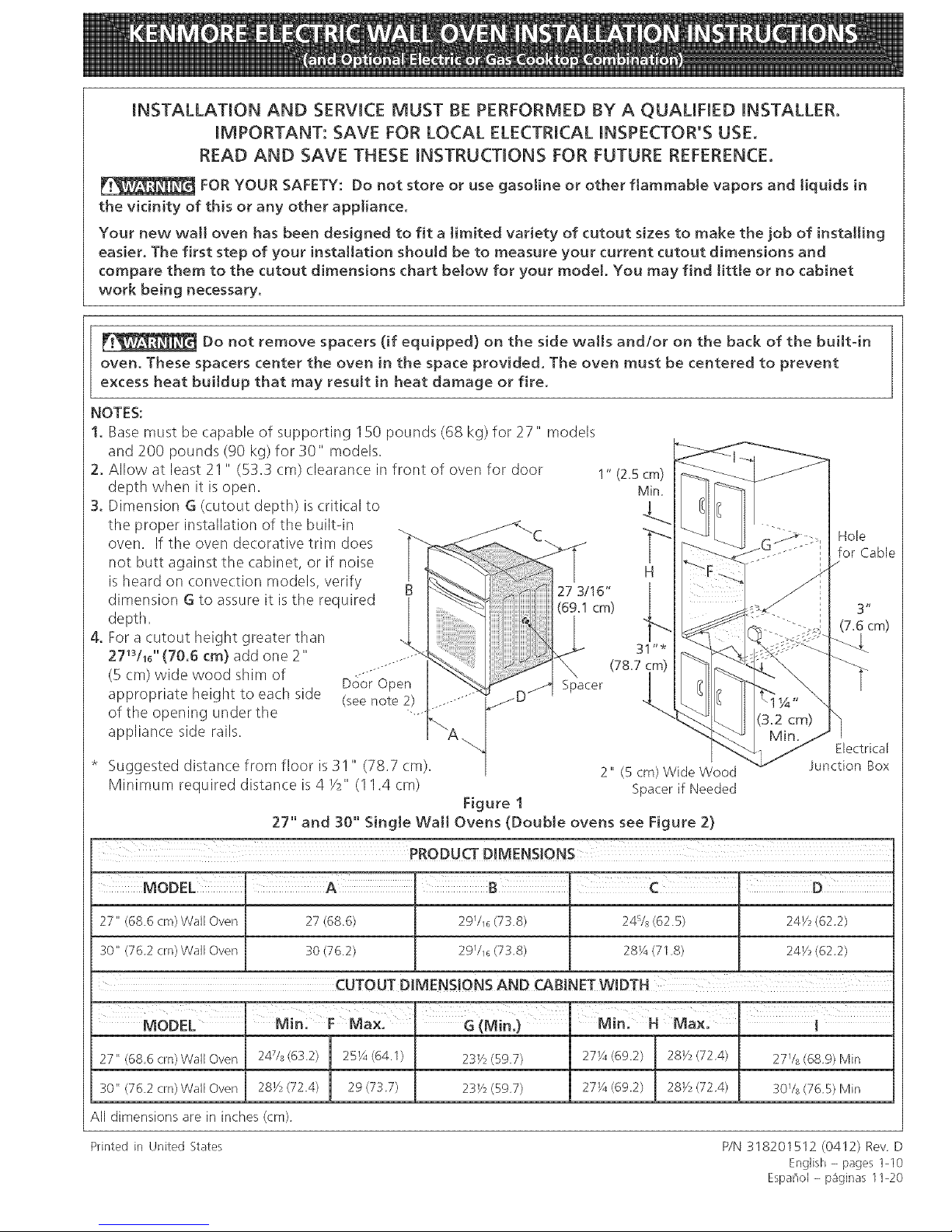
Your new wa[[ oven has been designed to fit a Jimited variety of cutout sizes to make the job of installing
easier. The first step of your installation should be to measure your current cutout dimensions and
compare them to the cutout dimensions chart below for your model, You may find little or no cabinet
work being necessary,
Do not remove spacers (if equipped) on the side walls and/or on the back of the bui[t4n
oven, These spacers center the oven in the space provided. The oven must be centered to prevent
excess heat buildup that may result in heat damage or fire,
NOTES:
1, Base must be capable of supporting 150 pounds (68 kg) for 27" models
and 200 pounds (90 kg) for 30" models.
2, Allow at least 21" (53.3 cm) clearance in front of oven for door 1"(25cm) _]_
depth when it isopen. " Min _- _-
3. Dimension G (cutout depth) is critical to ] " I
the proper installation of the built-in . _----<. _ < _ .
oven. If the oven decorative trim does C.. j '"_'[ _ _ /G-"_.- :: Hole.,
. E , - E. . ,r , i _ _ o o-_ ' TOF LaDle
no]: Dutt against the caD[he%or [Tnoise H J ""-F .... i /
is heard on convection models, verify ,,
dimension G to assure it is the required 27_'I;_i, [ ._,_
depth _ < _ '" "'" '7 6 cm_
i /_ - "">-8 k , f
4, For a cutout height greater than .. ", ] _ <_ '. €z-:s;--_ I
27 L0 (70.6 cm) add one 2 ...... _ _ o.< j ..... _. _ _
.--.......... _ _/_ / m} < _,,
(B cm) w,de wood shim of _---- _ _ _ , _<- _ t
" uoor upen _ K J,I Spacer I l r_ _ \ /
appropriate height to each side 'seenote 2.... J D/ I / _ _ t"_A, ,
. - t ) ....... _ " i_ 1¼"
of the opemng under the ....._ <"-_l'_ _-__ .... _ \
appliance side rails. A. "_ Min. /'J
_ "_ Electrical
* Suggested distance from floor is 3!" (78.7 cm). 2" (5cm) WideWood v Junction Box
Minimum required distance is 4 Y2" (I 1.4 cm) Spacer if Needed
.... Figure 1
27 and 30 Single Walt Ovens (Double ovens see Figure 2)
PRODUCT D[MENS!ONS
27" (686 cm)Wall Oven 27 (686)
30" (762 cm) Wall Oven 30 (76.2)
2971_ (738)
2971_ (738)
24% (625) 241h (622)
28¼ (71.8) 241h (622)
27" (686 cm) Wall Oven 2478 (63.2)
30" (762 cm) Wall Oven 281/_(724)
All dimensions are in inches (cm)
Printed in United States
25¼ (64.1)
29 (737)
271/4(69.2)
27¼ (69.2)
l
I
281/_(72.4) 2778 (689) Min
281/_(724) 301A (765) Min
P/N 318201512 (0412) Rev D
English - pages 1-10
Espai]ol - p_ginas 11-20
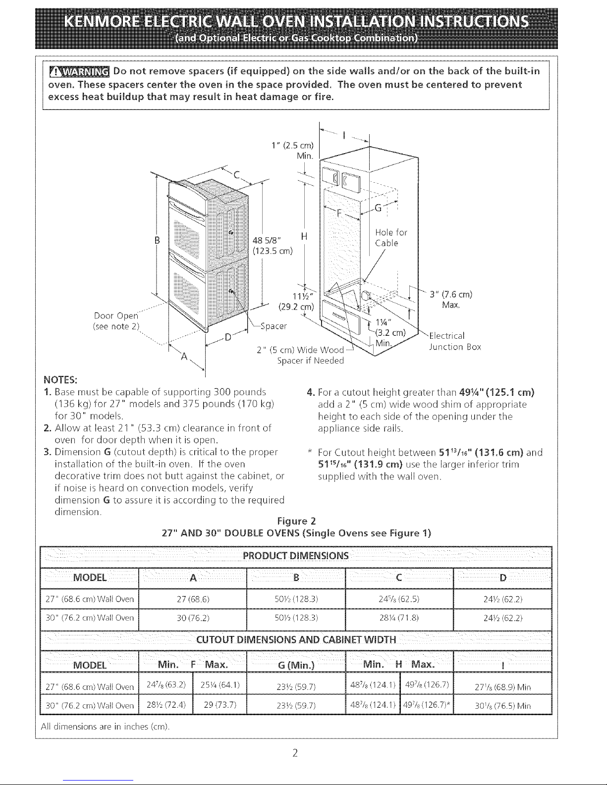
Do not remove spacers (if equipped) on the side wails and/or on the back of the bui[tdn
oven, These spacers center the oven in the space provided, The oven must be centered to prevent
excess heat buildup that may result in heat damage or fire,
I
1" (2.5cm)
Min.
B
Door Open
(seenote 2)
NOTES:
1. Base must be capable of supporting 300 pounds
(136 kg) for 27" models and 375 pounds (170 kg)
for 30" models.
2. Allow at least 21 " (53.3 cm) clearance in front of
oven for door depth when it is open.
3. Dimension G (cutout depth) is critical to the proper
installation of the builtdn oven. If the oven
decorative trim does not butt against the cabinet, or
if noise is heard on convection models, verify
dimension G to assure it is according to the required
dimension.
3" (7.6 cm)
Max.
2" (5 cm) Wide
Spacer if Needed
Junction Box
4. For a cutout height greater than 491/4"(125,1 cm)
add a 2" (5 cm) wide wood shim of appropriate
height to each side of the opening under the
appliance side rails.
* For Cutout height between 511U1d' (13!,6 cm) and
511shd' (131.9 cm) use the larger inferior trim
supplied with tile wall oven.
Figure 2
27" AND 30" DOUBLE OVENS (Single Ovens see Figure 1)
27" (68 6 era)Wall Oven 27(68.6) 50V2 (128 3) [ 24B/8(62.5) / 24V2 (62.2)
30" (76 2 crn)WaH Over_ 30(76.2) 50Y2(128 3) L_ 281A (718) ._ 24Y2 (62.2)
CUTOUT DIMENSIONS AND CAB!NET WIDTH
a×. nG(M - ×- i
I
MODEL Min F M n.) Min, H M
All dimensions are in inches (cm)
Important Notes to the [nstammer
1. Read all instructions contained in these installation
instructions before installing the wall oven.
2. Remove all packing material from the oven
compartments before connecting the electrical supply
to the wall oven.
3. Observe all governing codes and ordinances.
4. Be sure to leave these instructions with the consumer.
5. Oven door may be removed to facilitate installation.
6. THESE OVENS ARE NOT APPROVED FOR
STACKABLE OR SIDE-BY-SIDE INSTALLATION.
Important Note to the Consumer
Keep these instructions with your Owner's Guide for future
reference.
IMPORTANT SAFETY
[NSTRU S
Be sure your wall oven is installed and grounded
properly by a qualified installer or service
technidan.
• This wall oven must be electrkally grounded in
accordance with local codes or, in their absence,
with the Nationa[ EJectrica[ Code ANSJ/NFPA
No.70- tatest edition in United Sates, or with CSA
Standard C22.1, Canadian Electrical Code, Part 1, in
Canada.
Stepping, [eaning or sitting on the
door of this wall oven can resu[t in serious injuries
and can also cause damage to the wait oven.
Never use your wail oven for warming or heating
the room. Prolonged use of the wall oven without
adequate ventilation can be dangerous.
The electrical power to the oven must
be shut off while line connections are being made.
Failure to do so could result [n serious injury or
death.
1. Carpentry
Refer to figure I or 2 for the dimensions applicable to
your appliance, and the space necessary to receive the
oven. The oven support surface may be solid plywood or
similar material, however the surface must be level from
side to side and from front to rear.
2. Electrical Requirements
This appliance must be supplied with the proper voltage
and frequency, and connected to an individual, properly
grounded branch circuit, protected by a circuit breaker or
fuse, having amperage as noted on the rating plate (the
rating plate is located on the side trim.
Observe all governing codes and local ordinances
1. A 3-wire or 4-wire single phase 120/240 or 120/208
Volt, 60 Hz AC only electrical supply is required on
a separate circuit fused on both sides of the line
(time-delay fuse or circuit breaker is recommended).
DO NOT fuse neutral. The fuse size must not exceed
the circuit rating of the appliance specified on the
nameplate. Only certain cooktop models may be
installed over certain builtqn electric oven models.
Approved cooktops and builtqn ovens are listed by
the MFG ID number (see the insert sheet included in
the literature package).
2. The single wall oven can consume up to 4000W at
240Vac; use a circuit breaker of 30 Amp with wire
gauge #8 AWG. The double wall oven can consume
up to 8000W at 240Vac; use a circuit breaker of 40
Amp with wire gauge #8 AWG.
NOTE: Wire sizes and connections must conform with
the fuse size and rating of the appliance in accordance
with the American National Electrical Code ANSI/NFPA
No. 70qatest edition, or with Canadian CSA Standard
C22.1, Canadian Electrical Code, Part 1, and local codes
and ordinances.
An extension cord should not be used
with this appliance. Such use may result in a fire,
electrical shock, or other persona[ injury. If you need
a longer power cord you can order for purchase a 10'
(3 m) power cord kit #903056-9010 by calling the Sears
Parts & Repair Center at 1-800-4-MY-HOME ®,
3. These appliances should be connected to the fused
disconnect (or circuit breaker) box through flexible
armored or nonmetallic: sheathed cable. The flexible
armored (:able extending from the appliance should
be connected directly to the junction box. The
junction box should be located as shown in Figure 1
or Figure 2 and with as much slack as possible
remaining in the cable between the box and the
appliance, so it can be moved if servicing is ever
necessary.
4. A suitable strain relief must be provided to attach
the flexible armored cable to the junction box.
Electrical Shock Hazard
• E[ectrka[ ground [s required on this app!iance.
• Do not connect to the electrical supply until
appliance is permanently grounded,
• Disconnect power to the junction box before
making the eJectrkaJ connection,
• This appliance must be connected to a
grounded, metallic, permanent wiring system,
or a grounding connector should be connected
to the grounding terminal or wire lead on the
appliance.
• Do not use a gas supply line for grounding the
appliance.
Failure to do any of the above could result in a
fire, personaJ injury or electrical shock,
In cold weather shipping and storage
conditions, make sure that oven is in final location at
least three (3) hours before switching on power.
Switching on power while oven is still cold may damage
the oven controls.
3. Adjusting Oven Height
Oven height can be adjusted with 2" (5 cm) wide wood
shims when needed to fit into an existing cabinet cutout
opening, when cutout height exceeds 271s/16"(70.6 ¢m)
for the single wall oven or 491/_'' (125.1 cm) for the
double wall oven (see Figure 1 or 2). Place shims of
appropriate height beneath the oven side rails.
4. Electrical connection
It is the responsibility and obligation of the consumer to
contact a qualified installer to assure that the electrical
installation is adequate and is in conformance with the
National Electrical Code ANS!/NFPA No. 70datest
edition, or with CSA Standard C22.1, Canadian
Electrical Code, Part 1, and local codes and ordinances.
Electrical ground is required on this appliance.
These appliances are equipped with a copper conductor
flexible cable. If connection is made to aluminum house
wiring, use only special connectors which are approved
forjoining copper and aluminum wires in accordance
with National Electrical Code and local codes and
ordinances.
These appliances are manufactured with a white neutral
power supply wire and a frame connected green or bare
copper grounding wire.
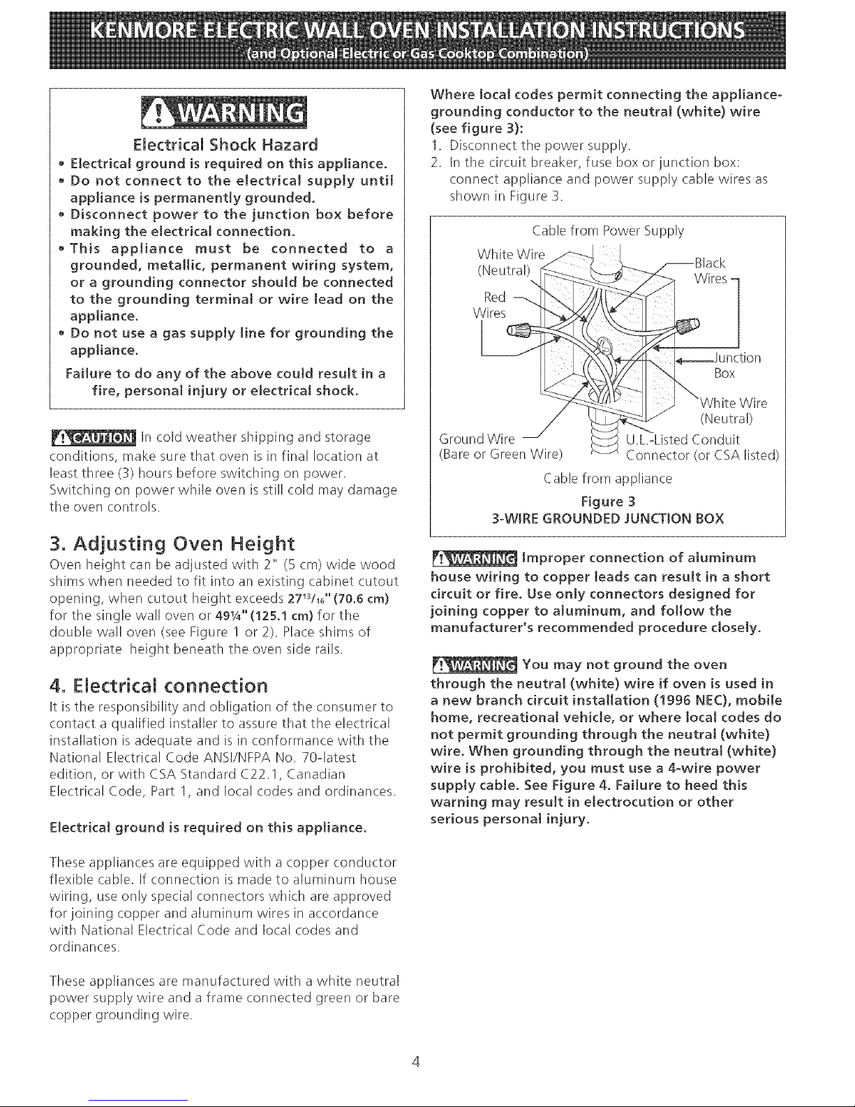
Where local codes permit connecting the appliance-
grounding conductor to the neutraJ (white) wire
(see figure 3):
1. Disconnect tile power supply.
2. In the circuit breaker, fuse box or junction box:
connect appliance and power supply (.able wires as
shown in Figure 3.
Cable from Power Supply
White Wire
(Neutral)
%
Red
Wires
Wires [
Box
Wire
(Neutral)
Ground Wire U.L-Listed Conduit
(Bare or Green Wire) Connector (or CSA listed)
Cable from appliance
Figure 3
3-WIRE GROUNDED JUNCTION BOX
[v_ Improper connection of aJuminum
house wiring to copper leads can result in a short
circuit or fire. Use only connectors designed for
joining copper to aJuminum, and follow the
manufacturer's recommended procedure closely.
You may not ground the oven
through the neutral (white} wire if oven is used in
a new branch circuit installation (1996 NEC), mobi[e
home, recreational vehicle, or where local codes do
not permit grounding through the neutra[ (white)
wire. When grounding through the neutraJ (white}
wire is prohibited, you must use a 4-wire power
supply cable. See Figure 4. Failure to heed this
warning may result in eJectrocution or other
serious personat injury.
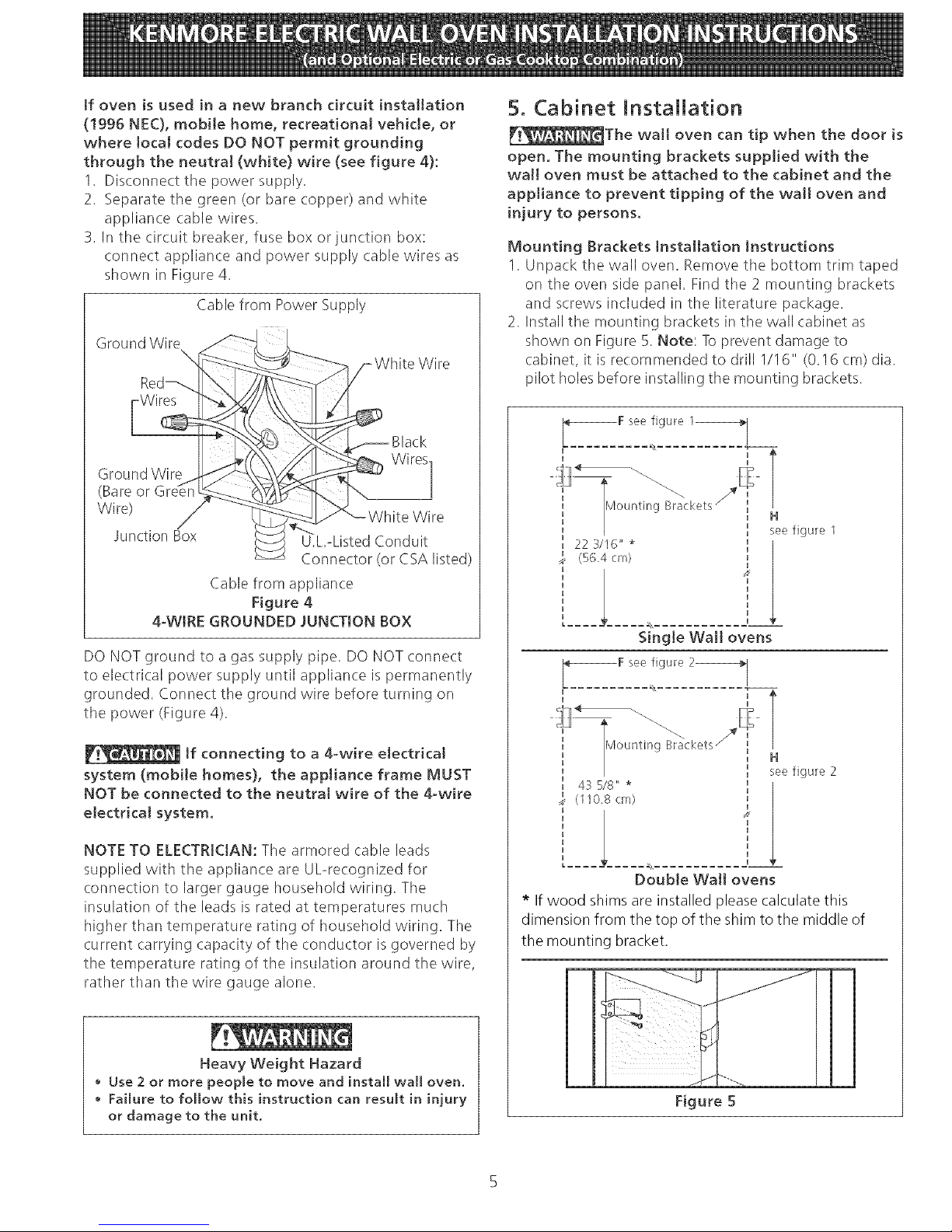
if oven is used in a new branch circuit installation
(!995 NEC), mobile home, recreational vehicle, or
where toca[ codes DO NOT permit grounding
through the neutra[ (white) wire (see figure 4):
1. Disconnect the power supply.
2. Separate the green (or bare copper) and white
appliance (:able wires.
3. In the circuit breaker, fuse box or junction box:
connect appliance and power supply cable wires as
shown in Figure 4.
Cable from Power Supply
Ground Wire
Wire
Wires
Black
Ground Wire
(Bare or
Wire)
Junction Box
U.L.-Listed Conduit
Connector (or CSA listed)
Cable from appliance
Figure 4
4-WIRE GROUNDED JUNCTtON BOX
DO NOT ground to a gas supply pipe. DO NOT connect
to electrical power supply until appliance is permanently
grounded. Connect the ground wire before turning on
the power (Figure 4).
[f connecting to a 4-wire electrical
system (mobile homes), the appliance frame MUST
NOT be connected to the neutra[ wire of the 4-wire
electrical system.
NOTE TO ELECTRICIAN: The armored (:able leads
supplied with the appliance are UUrecognized for
connection to larger gauge household wiring. The
insulation of the leads is rated at temperatures much
higher than temperature rating of household wiring. The
current carrying capacity of the conductor is governed by
the temperature rating of the insulation around the wire,
rather than the wire gauge alone.
Heavy Weight Hazard
Use 2 or more people to move and install wall oven.
Failure to follow this instruction can result in injury
or damage to the unit.
5. Cabinet Installation
[__The wall oven can tip when the door is
open. The mounting brackets supp!ied with the
wall oven must be attached to the cabinet and the
appliance to prevent tipping of the wall oven and
injury to persons.
Mounting Brackets Installation Instructions
1. Unpa(k the wall oven. Remove the bottom trim taped
on the oven side panel. Find the 2 mounting brackets
and screws included in the literature package.
2. Install the mounting brackets in the wall cabinet as
shown on Figure 5. Note: To prevent damage to
cabinet, it is recommended to drill 1/16" (0.16 cm) dia.
pilot holes before installing the mounting brackets.
22 3/I6" *
(56.4 cm)
H
see figure 1
Single Walt ovens
F see figure 2_
H
H
43 518" *
(110,8 cm)
T
H
see figure 2
Double Wall ovens
* If wood shims are installed please calculate this
dimension from the top of the shim to the middle of
the mounting bracket.
Figure 5
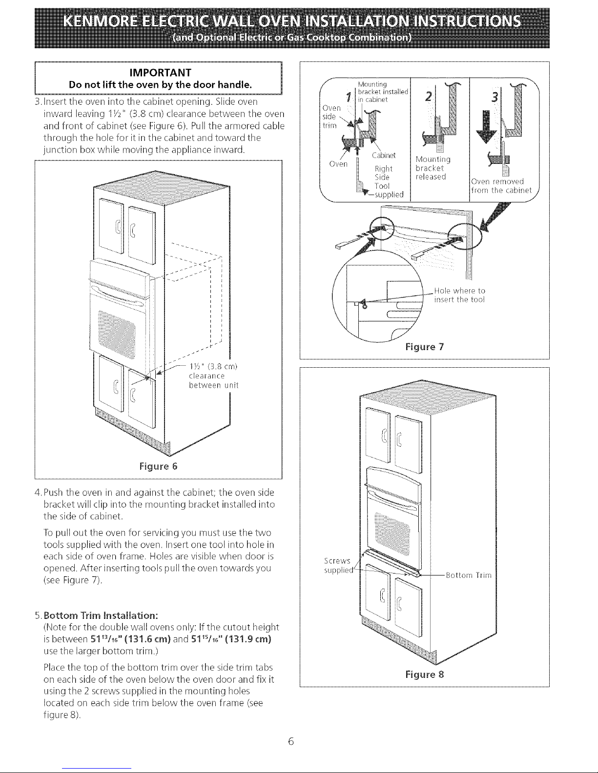
IMPORTANT
Do not lift the oven by the door handle.
3.Insert the oven into the cabinet opening. Slide oven
inward leaving IY2" (3,8 cm) clearance between the oven
and front of cabinet (seeFigure 6), Pull tile armored cable
through the hole for it in tile cabinet and toward the
junction box while moving the appliance inward.
J
lye" (3.8 cm)
clealance
between unit
Figure 6
4.Push the oven in and against the cabinet; the oven side
bracket will (:lip into tile mounting bracket installed into
the side of cabinet.
Topull out tile oven for servicing you must use the two
tools supplied with tile oven. Insert one tool into hole in
each side of oven frame. Holes are visible when door is
opened. After inserting tools pull the oven towards you
(see Figure 7).
5.Bottom Trim Installation:
(Note for the double wall ovens only: If the cutout height
is between 51_s/_6'' (!31.6 cm) and 51_s/_6'' (131.9 cm}
usetile larger bottom trim.)
Placethe top of tile bottom trim over the side trim tabs
on each side of the oven below the oven door and fix it
using the 2 screws supplied in the mounting holes
Io(ated on each side trim below tile oven frame (see
figure 8).
Mounting
bracket
released
Oven removed
from the cabinet
Hole where to
insert the tool
Figure 7
Screws
_Bottom Trim
Figure 8
 Loading...