

Kenmore 79046629505, 79046702603, 79046704603, 79046633603, 79046633602 Installation Instructions Manual
...
INSTALLATIONANDSERVICEMUSTBEPERFORMEDBYAQUALIFIEDINSTALLER.
IMPORTANT:SAVEFORLOCALELECTRICALINSPECTOR'SUSE.
READANDSAVETHESEINSTRUCTIONSFORFUTUREREFERENCE.
I
If the information in this manual is not followed exactly, a fire or explosion I _,,_-_'-_,
may result causing property damage, personal injury or death.
J
FOR YOUR SAFETY:
-- Do not store or usegasoline or other flammable vapors and liquids in the vicinity of this or any
other appliance.
-- WHATTO DO IFYOU SMELLGAS:
• Do not try to light any appliance.
• Do not touch any electrical switch; do not use any phone in your building.
• Immediately call your gas supplier from a neighbor's phone. Follow the gas supplier's instructions.
• If you cannot reach your gas supplier, call the fire department.
-- Installation and service must be performed by a qualified installer, service agency or the gas supplier.
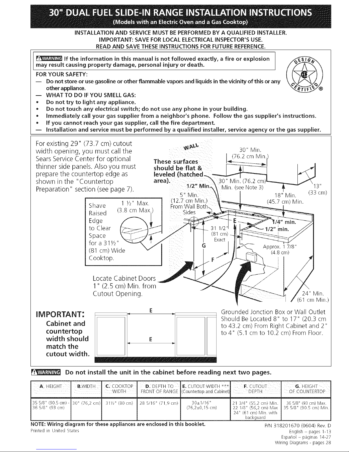
For existing 29" (73.7 cm) cutout
width opening, you must call the
Sears Service Center for optional
thinner side panels. Also you must
prepare the countertop edge as
shown in the "Countertop
Preparation" section (see page 7).
Shave 1 Y2" Max.
Raised (3.8 cm Max.
Edge
to Clear
Space
for a 311/2"
(81 cm) Wide
Cooktop.
These surfaces
should be flat &
leveled (hatched-_\
area).
112" Min.\
S" Min.
l 12.7 cm Min ,
From Wal Bott
Sides
30" Min.
(76.2 cm Min.
30" Min. (76.2
18" Min.
(45.7 cm) Min.
11
(33 cm)
Locate Cabinet Doors
1" (2.5 cm) Min. from
Cutout Opening.
24" Min.
(61 cm Min.)
IMPORTANT:
Cabinet and
cou ntertop
width should
match the
cutout width.
E
E
Grounded Jonction Box or Wall Outlet
Should Be Located 8" to 17" (20.3 cm
to 43.2 cm) From Right Cabinet and 2"
to4" (5.1 cm to 10.2 cm) From Floor.
Do not install the unit in the cabinet before reading next two pages.
A HEIGHT B.WIDTH C: COOKTOP D. DEPTH TO
m _ WIDTH FRONT OF RANGE
35 5/8" (90.5cm)- 30" (76,2 cm) 31Y2" (80cm) 28 5/16" (71,9cm)
36 5/8" (93 cm)
E. CUTOUT WIDTH ***
(Countertop and Cabinet
30+_1116"
(76,2_+0,15 cm)
NOTE: Wiring diagram for these appliances are enclosed in this booklet.
Printed in United States
F. cUTOUT' G. HEIGHT
DEPTH , OF COUNTERIOP
21 314" (55,2 cm) Min. 36 5/8" (93 cm) Max.
22 118" (56,2 cm) Max 35 5/8" (90.5 cm) Min.
24" (61 cm) Min. with
backguard
P/N 318201670 (0604) Rev. D
English - pages 1-13
Espat_ol - paginas 14-27
Wiring Diagrams - pages 28
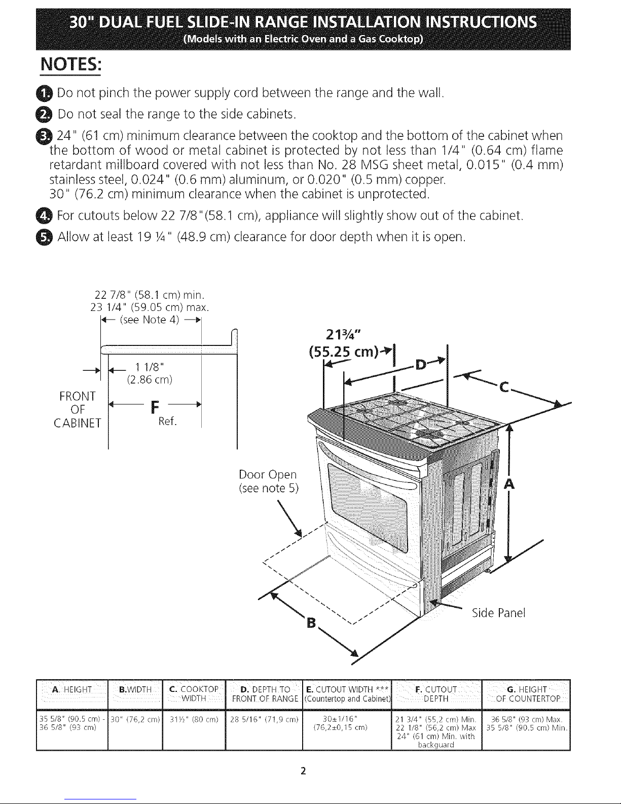
NOTES:
O!D Do not pinch the power supply cord between the range and the wall.
Do not seal the range to the side cabinets.
_t 24" (61 cm) minimum clearance between the cooktop and the bottom of the cabinet when
the bottom of wood or metal cabinet is protected by not less than 1/4" (0.64 cm) flame
retardant millboard covered with not less than No. 28 MSG sheet metal, 0.015" (0.4 mm)
stainless steel, 0.024" (0.6 mm) aluminum, or 0.020" (0.5 mm) copper.
30" (76.2 cm) minimum clearance when the cabinet is unprotected.
For cutouts below 22 7/8"(58.1 cm), appliance will slightly show out of the cabinet.
Allow at least 19 ¼" (48.9 cm) clearance for door depth when it is open.
22 7/8" (58.1 cm) min.
23 1/4" (59.05 cm) max.
(see Note 4) ---_
11/8"
(2.86 cm)
FRONT
OF _ F
CABINET Ref.
21¾"
(55.25 cm)" 1
Door Open
(see note 5)
/
A
Side Panel
I I I I
A. HEIGHT B.WIDTH C. COOKTOP D. DEPTH TO E. CUTOUT WIDTH *** F. CUTOUT G. HEIGHT
. . WIDTH FRONT QF RANGE (Countertop and Cabinet DEPTH OF COUNTERTOP
35 518" (90.5cm)- 30" (76,2 cm)
36 5/8" (93 cm)
31Y2" (80 cm} 28 5/16" (71,9 cm) 30±1/16"
(76,2±0,15 cm)
21 3/4" (55,2 cm} Min.
22 I/8" (56,2 cm} Max
24" (61 cm) Min. with
backguard
36 518" (93 cm) Max.
35 518" (90.5 cm} Min.
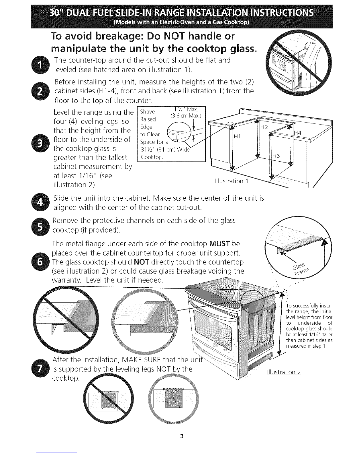
To avoid breakage: Do NOT handle or
manipulate the unit by the cooktop glass.
The counter-top around the cut-out should be flat and
leveled (see hatched area on illustration 1).
Before installing the unit, measure the heights of the two (2)
cabinet sides (H1-4), front and back (see illustration 1) from the
floor to the top of the counter.
Level the range using the
four (4)leveling legs so
that the height from the
floor to the underside of
the cooktop glass is
greater than the tallest
cabinet measurement by
at least 1/16" (see
illustration 2).
Shave 1 Y2"Max. 1
Raised (3.8 cm Max.)
I
Edge
to Clear
Space for
31Y2" (81 cm)Wic
Cooktop.
Illustration 1
Slide the unit into the cabinet. Make sure the center of the unit is
aligned with the center of the cabinet cut-out.
Remove the protective channels on each side of the glass
cooktop (if provided).
The metal flange under each side of the cooktop MUST be
placed over the cabinet countertop for proper unit support.
The glass cooktop should NOT directly touch the countertop
(see illustration 2) or could cause glass breakage voiding the
warranty. Level the unit if needed.
After the installation, MAKE SUREthat the uni
is supported by the leveling legs NOT by the
cooktop.
"To successfully install
the range, the initial
levelheight from floor
to underside of
cooktop glass should
be at least 1/16" taller
than cabinet sides as
measured in step 1.
Illustration 2
Important Notes to the InstalJer • Make sure the wall coverings around the range
can withstand the heat generated by the range.
1. Read all instructions contained in these installation
instructions before installing range.
2. Remove all packing material from the oven
compartments before connecting the gas and electrical
supply to the range.
3. Observe all governing codes and ordinances.
4. Be sure to leavethese instructions with the consumer.
Important Note to the Consumer
Keep these instructions with your Use& Care Guide for future
reference.
IMPORTANT SAFETY
INSTRUCTIONS
Installation of this range must conform with local codes
or, in the absence of local codes, with the National Fuel
Gas Code ANSI Z223. l--latest edition.
This range has been design certified by CSA
international. As with any appliance using gas and
generating heat, there are certain safety precautions you
should follow. You will find them in the Useand Care
Guide, read it carefully.
Be sure your range is installed and grounded
properly by a qualified installer or service
technician.
• This range must be electrically grounded in
accordance with local codes or, in their absence,
with the National Electrical Code ANSI/NFPA No.
70--latest edition. See Grounding Instructions on
page 6.
The installation of appliances designed for
manufactured (mobile) home installation must conform
with Manufactured Home Construction and Safety
Standard, title 24CFR, part 3280 [Formerly the Federal
Standard for Mobile Home Construction and Safety,
title 24, HUD (part 280)] or when such standard is not
applicable, the Standard for Manufactured Home
Installation 1982 (Manufactured Home Sites,
Communities and Setups), ANSI Z225.1/NEPA 501A-
latest edition, or with local codes.
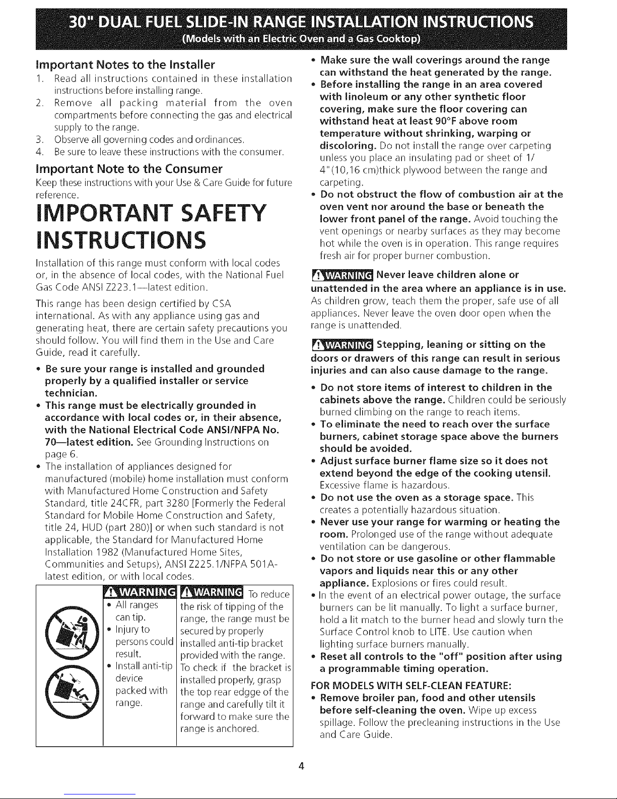
_ Toreduce
@
All ranges
can tip.
* Injury to
personscould
result.
Install anti-tip
device
packed with
range.
the risk of tipping of the
range, the range must be
secured by properly
installed anti-tip bracket
orovided with the range.
To check if the bracket is
installed properly, grasp
the top rear edgge of the
range and carefully tilt it
forward to make sure the
range isanchored.
• Before installing the range in an area covered
with linoleum or any other synthetic floor
covering, make sure the floor covering can
withstand heat at least 90°F above room
temperature without shrinking, warping or
discoloring. Do not install the range over carpeting
unless you place an insulating pad or sheet of 1/
4"(10,16 cm)thick plywood between the range and
carpeting.
• Do not obstruct the flow of combustion air at the
oven vent nor around the base or beneath the
lower front panel of the range. Avoid touching the
vent openings or nearby surfaces as they may become
hot while the oven is in operation. This range requires
fresh air for proper burner combustion.
Never leave children alone or
unattended in the area where an appliance is in use.
As children grow, teach them the proper, safe use of all
appliances. Never leave the oven door open when the
range is unattended.
Stepping, leaning or sitting on the
doors or drawers of this range can result in serious
injuries and can also cause damage to the range.
• Do not store items of interest to children in the
cabinets above the range. Children could be seriously
burned climbing on the range to reach items.
• To eliminate the need to reach over the surface
burners, cabinet storage space above the burners
should be avoided.
• Adjust surface burner flame size so it does not
extend beyond the edge of the cooking utensil.
Excessive flame is hazardous.
• Do not use the oven as a storage space. This
creates a potentially hazardous situation.
• Never use your range for warming or heating the
room. Prolonged use of the range without adequate
ventilation can be dangerous.
• Do not store or use gasoline or other flammable
vapors and liquids near this or any other
appliance. Explosions or fires could result.
• In the event of an electrical power outage, the surface
burners can be lit manually. To light a surface burner,
hold a lit match to the burner head and slowly turn the
Surface Control knob to LITE.Use caution when
lighting surface burners manually.
• Reset all controls to the "off" position after using
a programmable timing operation.
FOR MODELS WITH SELF-CLEAN FEATURE:
• Remove broiler pan, food and other utensils
before self-cleaning the oven. Wipe up excess
spillage. Follow the precleaning instructions in the Use
and Care Guide.
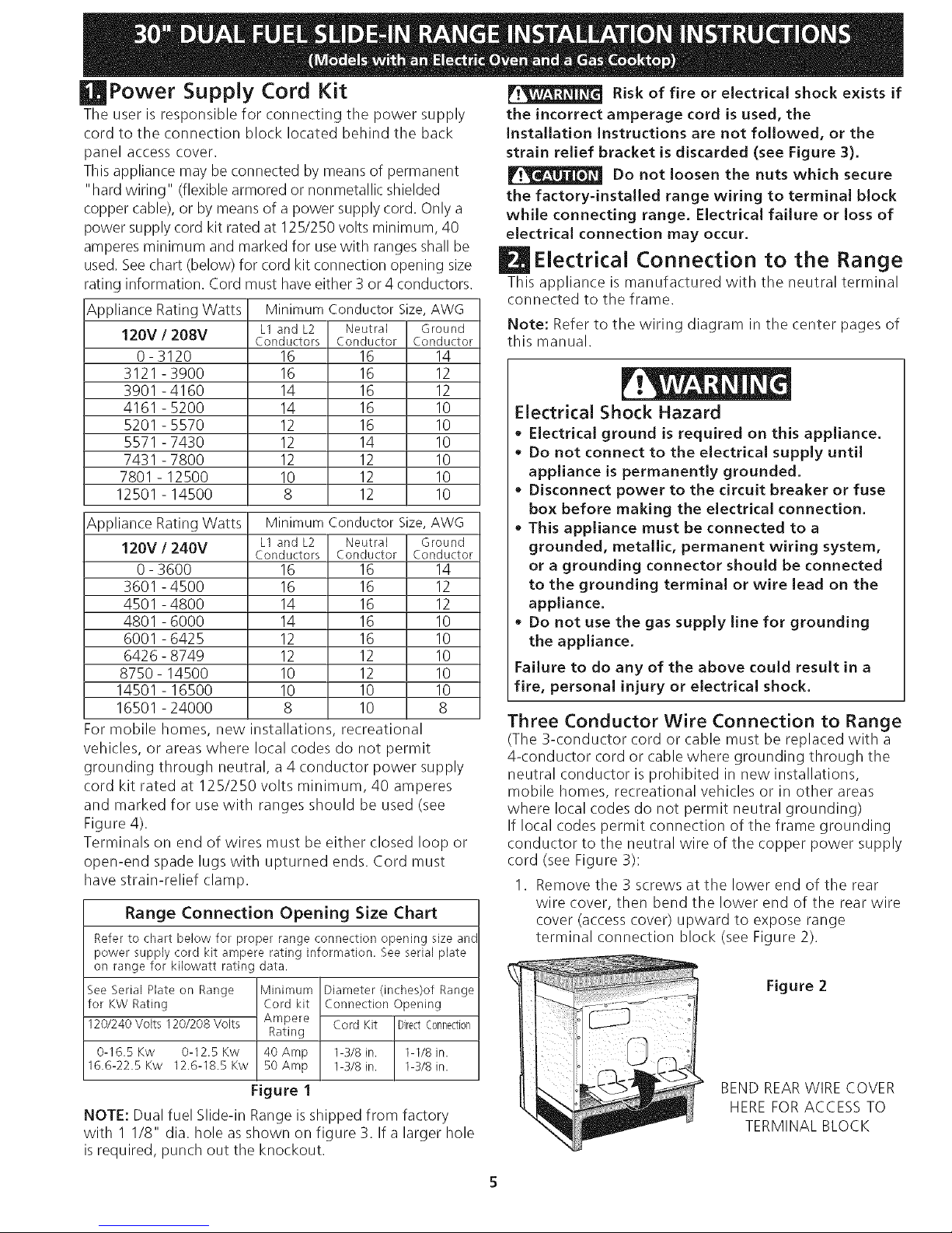
Power Supply Cord Kit
The user is responsible for connecting the power supply
cord to the connection block located behind the back
panel access cover.
This appliance may be connected by means of permanent
"hard wiring" (flexible armored or nonmetallic shielded
copper cable), or by means of a power supply cord. Only a
power supply cord kit rated at 125/250 volts minimum, 40
amperes minimum and marked for usewith ranges shall be
used. Seechart (below) for cord kit connection opening size
rating information. Cord must have either 3 or 4 conductors.
Appliance Rating Watts Minimum Conductor Size, AWG
120V/208V L1 and L2 Neutral Ground
Conductors Conductor Conductor
0-3120 16 16 14
3121-3900 16 16 12
3901-4160 14 16 12
4161-5200 14 16 10
5201-5570 12 16 10
5571-7430 12 14 10
7431-7800 12 12 10
7801-12500 10 12 10
12501-14500 8 12 10
Appliance Rating Watts Minimum Conductor Size, AWG
120V / 240V L1 and L2 Neutral Ground
Conductors Conductor Conductor
0-3600 16 16 14
3601-4500 16 16 12
4501-4800 14 16 12
4801-6000 14 16 10
6001-6425 12 16 10
6426-8749 12 12 10
8750-14500 10 12 10
14501-16500 10 10 10
16501-24000 8 10 8
For mobile homes, new installations, recreational
vehicles, or areas where local codes do not permit
grounding through neutral, a 4 conductor power supply
cord kit rated at 125/250 volts minimum, 40 amperes
and marked for use with ranges should be used (see
Figure 4).
Terminals on end of wires must be either closed loop or
open-end spade lugs with upturned ends. Cord must
have strain-relief clamp.
Range Connection Opening Size Chart
Refer to chart below for proper range connection opening size anc
power supply cord kit ampere rating information. See serial plate
on range for kilowatt rating data.
SeeSerial Hate on Range Minimum Diameter (inches)of Range
for KWRating Cord kit Connection Opening
120/240 Volts 120/208 Volts Ampere Cord Kit DirectConnection
Rating
0-16.5 Kw 0-12.5 Kw 40 Amp 1-3/8 in. 1-1/8 in.
16.6-22.5Kw 12.6-18.5Kw 50Amp 1-3/8in. 1-3/8in.
Figure 1
NOTE: Dual fuel Slide-in Range isshipped from factory
with 1 1/8" dia. hole asshown on figure 3. Ifa larger hole
is required, punch out the knockout.
Risk of fire or electrical shock exists if
the incorrect amperage cord is used, the
installation instructions are not followed, or the
strain relief bracket is discarded (see Figure 3).
Do not loosen the nuts which secure
the factory-installed range wiring to terminal block
while connecting range. Electrical failure or Jossof
electrical connection may occur.
Electrical Connection to the Range
This appliance is manufactured with the neutral terminal
connected to the frame.
Note: Refer to the wiring diagram in the center pages of
this manual.
Electrical Shock Hazard
• Electrical ground is required on this appliance.
• Do not connect to the electrical supply until
appliance is permanently grounded.
• Disconnect power to the circuit breaker or fuse
box before making the electrical connection.
• This appliance must be connected to a
grounded, metallic, permanent wiring system,
or a grounding connector should be connected
to the grounding terminal or wire lead on the
appliance.
• Do not use the gas supply line for grounding
the appliance.
Failure to do any of the above could result in a
fire, personal injury or electrical shock.
Three Conductor Wire Connection to Range
(The 3-conductor cord or cable must be replaced with a
4-conductor cord or cable where grounding through the
neutral conductor is prohibited in new installations,
mobile homes, recreational vehicles or in other areas
where local codes do not permit neutral grounding)
If local codes permit connection of the frame grounding
conductor to the neutral wire of the copper power supply
cord (see Figure 3):
I. Remove the 3 screws at the lower end of the rear
wire cover, then bend the lower end of the rear wire
cover (access cover) upward to expose range
terminal connection block (see Figure 2).
Figure 2
BEND REARWIRE COVER
HEREFORACCESS TO
TERMINAL BLOCK
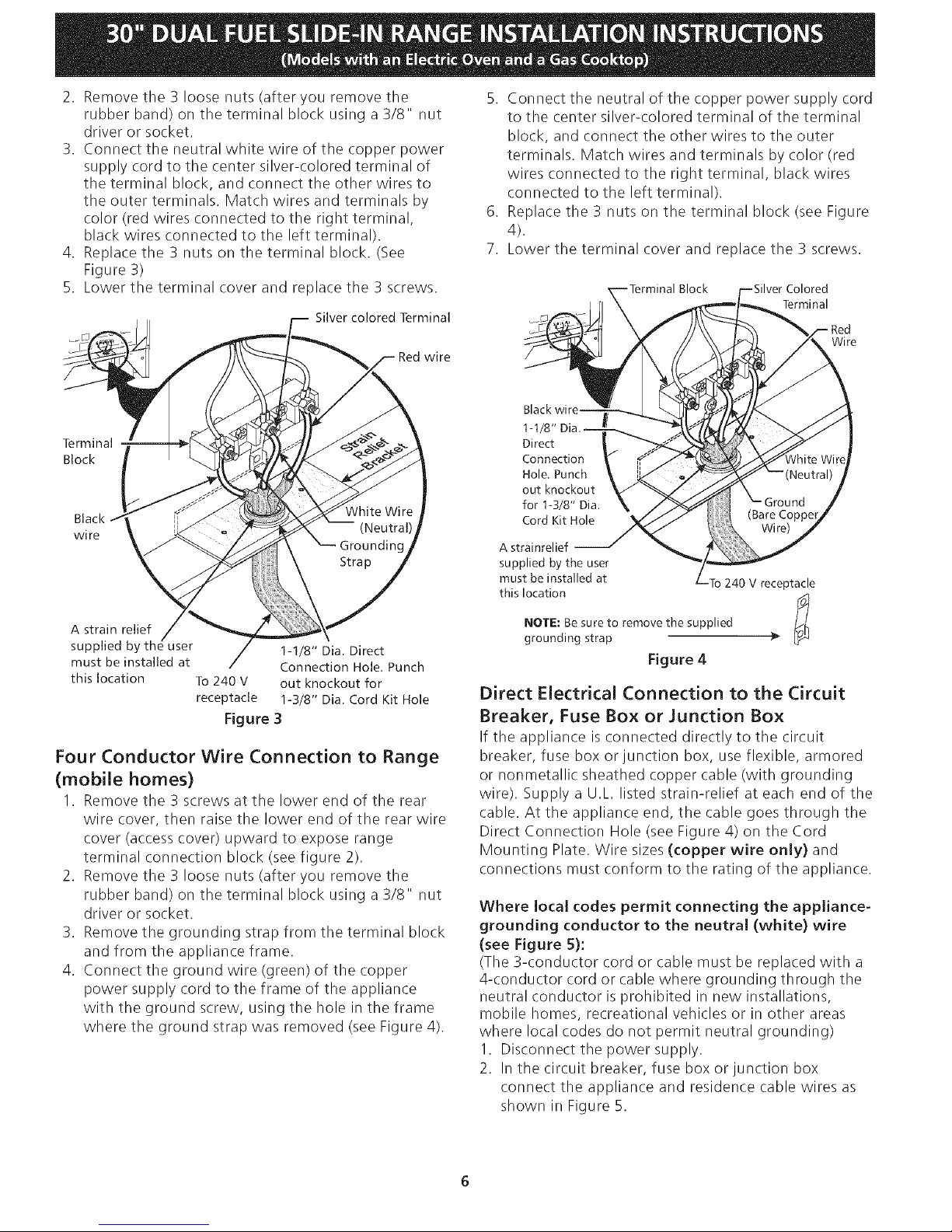
2. Removethe3loosenuts(afteryouremovethe
rubberband)ontheterminalblockusinga3/8"nut
driverorsocket.
3. Connect the neutral white wire of the copper power
supply cord to the center silver-colored terminal of
the terminal block, and connect the other wires to
the outer terminals. Match wires and terminals by
color (red wires connected to the right terminal,
black wires connected to the left terminal).
4. Replace the 3 nuts on the terminal block. (See
Figure 3)
5. Lower the terminal cover and replace the 3 screws.
Silver colored Terminal
5. Connect the neutral of the copper power supply cord
to the center silver-colored terminal of the terminal
block, and connect the other wires to the outer
terminals. Match wires and terminals by color (red
wires connected to the right terminal, black wires
connected to the left terminal).
6. Replace the 3 nuts on the terminal block (see Figure
4).
7. Lower the terminal cover and replace the 3 screws.
Block
Terminal
Wi re
Terminal
Block
Black
wi re
A strain relief
supplied by the user 1-1/8" Dia. Direct
must be installed at Connection Hole. Punch
this location To 240 V out knockout for
receptacle 1-3/8" Dia. Cord Kit Hole
Figure 3
Four Conductor Wire Connection to Range
(mobile homes)
1. Remove the 3 screws at the lower end of the rear
wire cover, then raise the lower end of the rear wire
cover (access cover) upward to expose range
terminal connection block (see figure 2).
2. Remove the 3 loose nuts (after you remove the
rubber band) on the terminal block using a 3/8" nut
driver or socket.
3. Remove the grounding strap from the terminal block
and from the appliance frame.
4. Connect the ground wire (green) of the copper
power supply cord to the frame of the appliance
with the ground screw, using the hole in the frame
where the ground strap was removed (see Figure 4).
Black
Direct
Connection
Hole. Punch
out knockout
for 1-3/8" Dia.
Cord Kit Hole
A strainrelief
supplied by the user
must be installed at 240 V receptacle
this location
r_
NOTE: Be sure to remove the supplied F'I
grounding strap _"
Figure 4
Direct Electrical Connection to the Circuit
Breaker, Fuse Box or Junction Box
If the appliance is connected directly to the circuit
breaker, fuse box or junction box, use flexible, armored
or nonmetallic sheathed copper cable (with grounding
wire). Supply a U.L listed strain-relief at each end of the
cable. At the appliance end, the cable goes through the
Direct Connection Hole (see Figure 4) on the Cord
Mounting Plate. Wire sizes (copper wire only) and
connections must conform to the rating of the appliance.
Where local codes permit connecting the appliance-
grounding conductor to the neutral (white) wire
(see Figure 5):
(The 3-conductor cord or cable must be replaced with a
4-conductor cord or cable where grounding through the
neutral conductor is prohibited in new installations,
mobile homes, recreational vehicles or in other areas
where local codes do not permit neutral grounding)
1. Disconnect the power supply.
2. In the circuit breaker, fuse box or junction box
connect the appliance and residence cable wires as
shown in Figure 5.
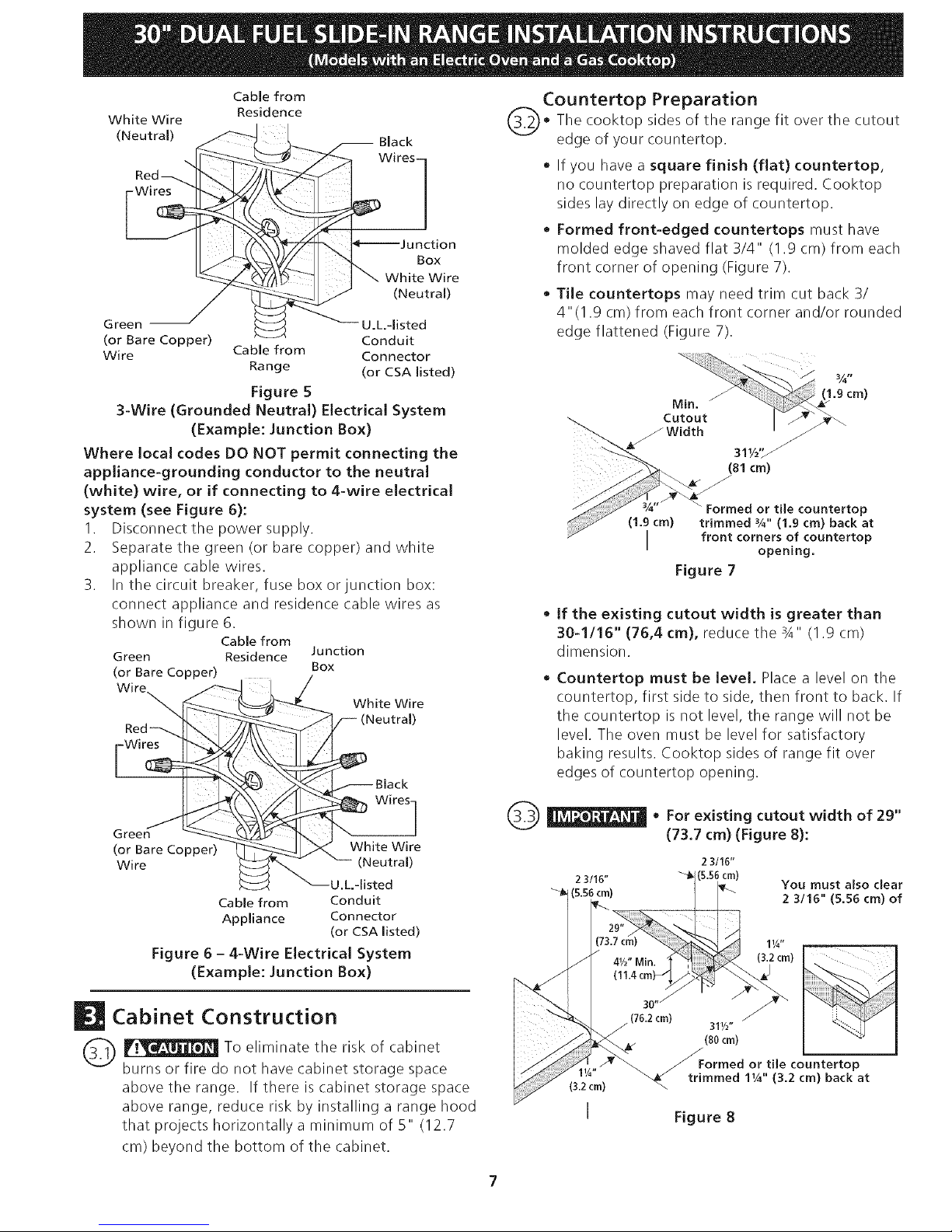
White Wire
(Neutral)
Cable from
Residence
-- Black
Wires !
)n
Box
White Wire
(Neutral)
Green -- U.L.-listed
(or Bare Copper) Conduit
Wire Cable from Connector
Range (or CSA listed)
Figure 5
3-Wire (Grounded Neutral) Electrical System
(Example: Junction Box)
Where local codes DO NOT permit connecting the
appliance-grounding conductor to the neutral
(white) wire, or if connecting to 4-wire electrical
system (see Figure 6):
I. Disconnect the power supply.
2. Separate the green (or bare copper) and white
appliance cable wires.
3. In the circuit breaker, fuse box or junction box:
connect appliance and residence cable wires as
shown in figure 6.
Cable from
Green Residence Junction
(or Bare Copper) Box
Wire
Green
(or Bare Copper)
Wire
White Wire
/-- (Neutral)
-- Black
White Wire
(Neutral)
U.L.-listed
Cable from Conduit
Appliance Connector
(or CSA listed)
Figure 6 - 4-Wire Electrical System
(Example: Junction Box)
Cabinet Construction
_ :_ To eliminate the risk of cabinet
burns or fire do not have cabinet storage space
above the range. If there is cabinet storage space
above range, reduce risk by installing a range hood
that projects horizontally a minimum of 5" (12.7
cm) beyond the bottom of the cabinet.
Countertop Preparation
@_ The cooktop sides of the fit over the cutout
range
edge of your countertop.
• If you have a square finish (flat) countertop,
no countertop preparation is required. Cooktop
sides lay directly on edge of countertop.
• Formed front-edged countertops must have
molded edge shaved flat 3/4" (1.9 cm) from each
front corner of opening (Figure 7).
• Tile countertops may need trim cut back 3/
4"(1.9 cm) from each front corner and/or rounded
edge flattened (Figure 7).
_'_.. _/Width z
_.. 311/2"_ _
81 cm)
Formed or tile countertop
ed ¼" (1.9 cm) back at
/ I front corn2prSOfngOU nte rto p
Figure 7
if the existing cutout width is greater than
30-1116" (76,4 cm), reduce the 3A" (1.9 cm)
dimension.
Countertop must be level. Place a level on the
countertop, first side to side, then front to back. If
the countertop is not level, the range will not be
level. The oven must be level for satisfactory
baking results. Cooktop sides of range fit over
edges of countertop opening.
For existing cutout width of 29"
(73.7 cm) (Figure 8):
2 3/16"
2 3/16" (5.56 cm)
You must also clear
(5.56 cm) 2 3/16" (5.56 cm) of
11/4"
4W' Min. t(3"2crn) [
11.4 cm} ,_
3°"j "_
z(762cm) 31,/2" I
/ (80 cm)
/ Formed or tile countertop
_-_ trimmed 1W' (3.2 cm) back at
Figure 8
Gas Supply - InstaJlation
When shipped from the factory, this unit is designed to
operate on 4"(10,16 cm) water column (1.0 kPa) Natural
gas manifold pressure. A convertible pressureregulator is
connected to the range manifold and MUST be connected
in series with the gas supply line. To accessthe regulator,
remove the drawer.
For proper operation, the maximum inlet pressure to
the regulator should be no more than 14"(35,56 era)of
water column pressure (3.5 kPa).
The inlet pressure to the regulator must be at least 1" (.25
kPa)greater than the regulator manifold pressure setting.
The regulator is setfor 4"(I 0,16 cm)water column (1.0
kPa) Natural gas manifold pressure; the inlet pressure must
be at least 5"(12.60 cm)water column (1.25 kPa) Natural
gas. For LP/Propanegas, the regulator must be set for
10"(25,4 cm)water column (2.5 kPa) manifold pressure; the
inlet pressure must be at least 11"(27,9 era)water column
(2.75 kPa).
The supply line should be equipped with an approved
shutoff valve (see Figure 11). This valve should be located
in the same room asthe range and should be in a location
that allows easeof opening and closing. Do not block
accessto the shutoff valve. The valve is for turning on or
shutting off gas to the appliance.Open the shutoff valve in
the gas supply line. Wait a few minutes for gas to move
through the gas line.
The gas supply between the shutoff valve and the regulator
may be connected by rigid piping or by A.G.A./C.G.A.-
approved flexible metallic union-connected piping where
local codes permit use.
The gas supply piping can bethrough the side wall of the
right cabinet. The right side cabinet isan ideal location for
the main shutoff valve.
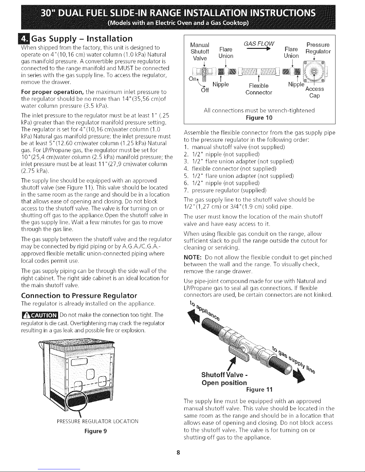
Connection to Pressure Regulator
The regulator is already installed on the appliance.
Do not makethe connection too tight. The
regulator is die cast.Overtightening maycrackthe regulator
resulting in a gas leak and possiblefire or explosion.
Manual GAS FLOW Pressure
Shutoff Flare _'_ Flare Regulator
Valve Union Union
Nipple Flexible Nipple ] I ........
Off Connector Access
Cap
All connections must be wrench-tightened
Figure 10
Assemble the flexible connector from the gas supply pipe
to the pressure regulator in the following order:
I. manual shutoff valve (not supplied)
2. 1/2" nipple (not supplied)
3. 1/2" flare union adapter (not supplied)
4. flexible connector (not supplied)
5. 1/2" flare union adapter (not supplied)
6. 1/2" nipple (not supplied)
7. pressure regulator (supplied)
The gas supply line to the shutoff valve should be
I/2"(1,27 cm) or 3/4"(1.9 cm) solid pipe.
The user must know the location of the main shutoff
valve and have easy access to it.
When using flexible gas conduit on the range, allow
sufficient slack to pull the range outside the cutout for
cleaning or servicing.
NOTE: Do not allow the flexible conduit to get pinched
between the wall and the range. To visually check,
remove the range drawer.
Use pipe-joint compound made for usewith Natural and
LP/Propane gas to seal all gas connections. If flexible
connectors are used, be certain connectors are not kinked.
t5
PRESSUREREGULATORLOCATION
Figure g
Shutoff Valve =
Open position
Figure 11
The supply line must be equipped with an approved
manual shutoff valve. This valve should be located in the
same room as the range and should be in a location that
allows ease of opening and closing. Do not block access
to the shutoff valve. The valve isfor turning on or
shutting off gas to the appliance.
Onceregulatorisinplace,opentheshutoffvalveinthe
gassupplyline.Waitafewminutesfor gastomove
throughthegasline.
Leaktestingof the applianceshallbeconducted
according to the manufacturer's instructions.
Check for leaks. After connecting the rangeto the gassupply,
check the systemfor leakswith a manometer. If a manometer
is not available,turn on the gas supply and usea liquid leak
detector at alljoints and connections to checkfor leaks.
Do not use a flame to check for leaks
from gas connections. Checking for leaks with a flame
may result in a fire or explosion.
All openings in the wall or floor where the range is to be
installed must be sealed.
Tighten all connections if necessary to prevent gas
leakage in the cooktop or supply line.
Disconnect this range and its individual shutoff
valve from the gas supply piping system during any
pressure testing of the system at test pressures greater
than I/2 psig (3.5 kPa or 14"(35,56 era)water column).
isolate the range from the gas supply piping system
by closing its individual manual shutoff valve during any
pressure testing of the gas supply piping system at test
pressures equal to or less than 1/2 psig (3.5 kPa or
14"(35,56 cm) water column).
LP/Propane Gas Conversion
Thisappliance can be used with Natural gas or LP/Propane
gas. It isshippedfrom the factory for usewith naturalgas.
If you wish to convert your range for use with LP/Propane
gas, use the supplied fixed orifices located in a bag
containing the literature marked "FOR LP/PROPANE GAS
CONVERSION." Follow the instructions packaged with
the orifices.
Moving the Appliance for
Servicing and Cleaning
Turn off the range line fuse or circuit breakers at the main
power source, and turn off the manual gas shut-off valve.
Make sure the range is cold. Remove the service drawer
(warmer drawer on some models) and open the oven door.
Lift the range at the front and slide it out of the cut-out
opening without creating undue strain on the flexible gas
conduit. Make sure not to pinch the flexible gas conduit at
the back of the range when replacing the unit into the cut-
out opening. Replace the drawer, close the door and switch
on the electrical power and gas to the range.
The conversion must be performed by a qualified service
technician in accordance with the manufacturer's
instructions and all local codes and requirements. Failure
to follow these instructions could result in serious injury
or property damage. The qualified agency performing
this work assumes responsibility for the conversion.
Failure to make the appropriate
conversion can result in personal injury and property
damage.
 Loading...