

iNSTALLATiON AND SERVICE MUST BE PERFORMED BY A QUALiFiED iNSTALLER.
iMPORTANT: SAVE FOR LOCAL ELECTRICAL iNSPECTOR'S USE.
READ AND SAVE THESE iNSTRUCTiONS FOR FUTURE REFERENCE.
FOR YOUR SAFETY: Do not store or use gasoline or other flammable vapors and liquids in
the vicinity of this or any other appliance.
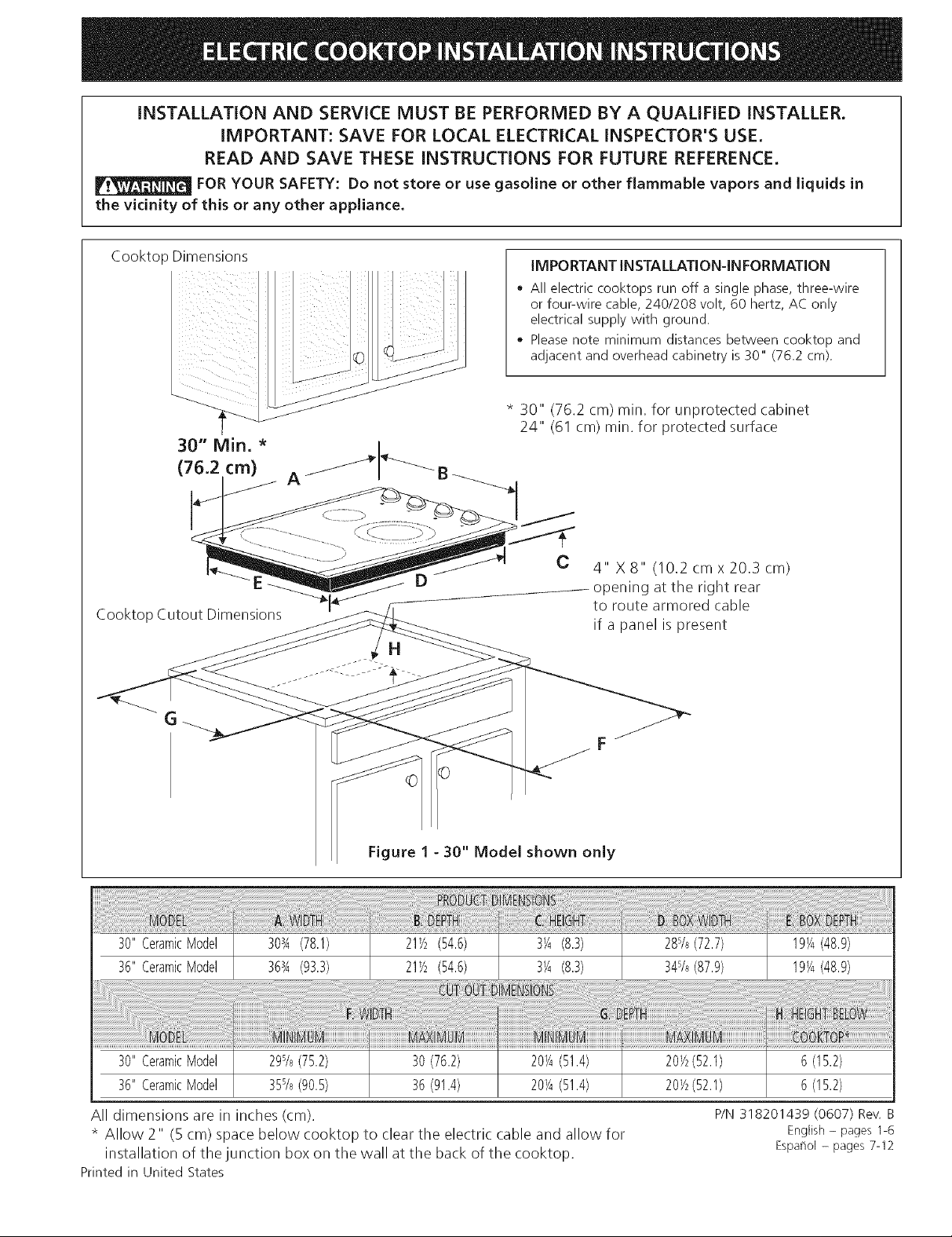
Cooktop Dimensions
Cooktop Cutout Dimensions
IMPORTANT INSTALLATION-IN FORMATION
® All electric cooktops run off a single phase, three-wire
or four-wire cable, 240/208 volt, 60 hertz, AC only
electrical supply with ground.
* Please note minimum distances between cooktop and
adjacent and overhead cabinetry is 30" (76.2 cm).
* 30" (76.2 cm) rain. for unprotected cabinet
24" (61 cm) rain. for protected surface
C 4" x 8" (10.2 cmx 20.3 cm)
opening at the right rear
to route armored cable
if a panel is present
©
Figure 1 - 30" Model shown only
!!ii! i !ii i ii i i i i! !i ii i i i ! i !i iiiiiiiiiiiiiiiii!ii!ii!ii!ii!iii!i iiiiiiiii i !i i !i!iii!i!i! !! !! !ii!i i iiiiiiiiiiiiiiiiii i! i!!i! i!!i! i i i i i !i!!ii!i!!!i!i!!i!!i!!i!!i!!i!!ii!i!iii! ! iii !ii i
30"CeramicModel 303A(78.1) 21_/2(54.6) 3_A(8.3) 28s/s(72.7) 19V,_(48.9)
36"CeramicModel 363A(93.3) 21_/2(54.6) 3_A(8.3) 34s/s(87.9) 19V,_(48.9)
30"CeramicModel 29s%(75.2) 30 (76.2) 20_A(51.4) 20½(52.1) 6 (15.2)
36"CeramicModel 35s%(90.5) 36 (91.4) 20¼(51.4) 20½(52.1) 6 (15.2)
All dimensions are in inches (cm).
* Allow 2" (5 cm) space below cooktop to clear the electric cable and allow for
installation of the junction box on the wall at the back of the cooktop.
Printedin United States
P/N 318201439 (0607) Rev.
English - pages 1-6
Espa_iol - pages 7-12
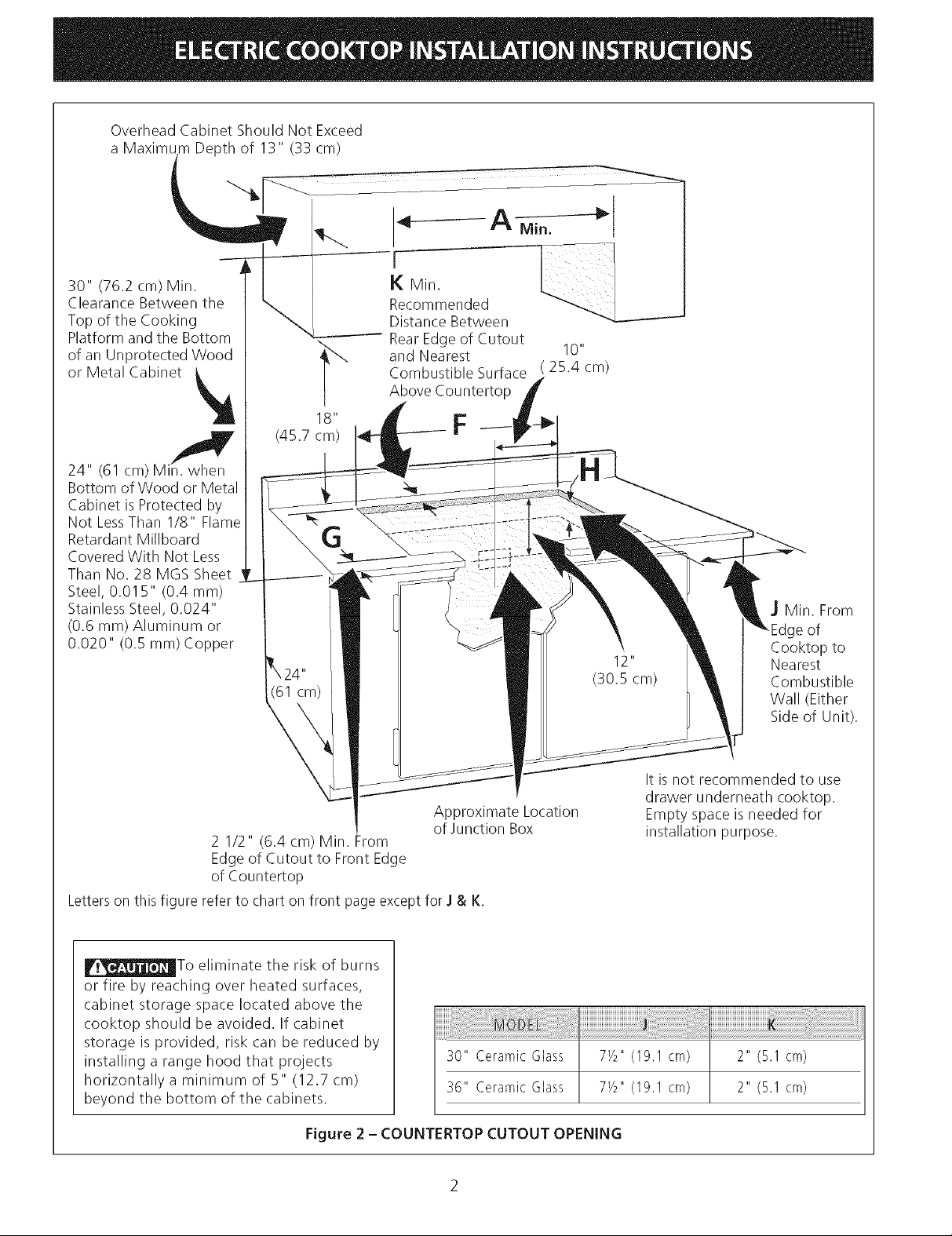
Overhead Cabinet Should Not Exceed
a Maximum Depth of 13" (33 cm)
30" (76.2 cm) Min.
Clearance Between the
Top of the Cooking
Platform and the Bottom
of an Unprotected Wood
or Metal Cabinet _
/
24" (61 cm)Mi_
Bottom of Wood or Metal
Cabinet is Protected by
Not LessThan 1/8" Flame
Retardant Millboard
Covered With Not Less
Than No. 28 MGS Sheet
Steel, 0.015" (0.4 ram)
Stainless Steel, 0.024"
(0.6 ram) Aluminum or
0.020" (0.5 ram) Copper
18"
(45.7 cm)
A Min.
Recommended
Distance Between
RearEdge of Cutout
and Nearest 10"
Combustible Surface (25.4 cm)
Above Countertop
F
I
J Min. From
of
Cooktop to
Nearest
Combustible
Wall (Either
Side of Unit).
Approximate Location
of Junction Box
2 1/2" (6.4 cm) Min. From
Edge of Cutout to Front Edge
of Countertop
Letterson this figure refer to chart on front pageexcept for J & K.
_To eliminate the risk of burns
or fire by reaching over heated surfaces,
cabinet storag_ ._,u_ located above the
cooktop should be avoided. If cabinet
storage is provided, risk can be reduced by
installing a range hood that projects
horizontally a minimum of 5" (12.7 cm)
bevond the bottom of the cabinets.
Figure 2 - COUNTERTOP CUTOUT OPENING
30" Ceramic Glass
36" Ceramic Glass
It is not recommended to use
drawer underneath cooktop.
Empty space is needed for
installation purpose.
Important Notes to the InstaJJer
I. Readall instructions contained in these installation
instructions before installing the cooktop.
2. Remove all packing material before connecting the
electrical supply to the cooktop.
3. Observe all governing codes and ordinances.
4. Be sure to leavethese instructions with the consumer.
2. These units can consume up to 8600W at 240 Vac, a
circuit breaker of 40 Amp is recommended.
NOTE: Wire sizes and connections must conform with
the fuse size and rating of the appliance in accordance
with the National Electrical Code ANSI/NFPA No. 70-
latest edition, and local codes and ordinances.
Important Note to the Consumer
Keep these instructions with your Use and Care Guide for
future reference.
IMPORTANT SAFETY
INSTRUCTIONS
• Be sure your cooktop is instaJJed and grounded
properJy by a qualified installer or service
technician.
• These cooktops must be eJectricaJJy grounded in
accordance with JocaJ codes or, in their absence,
with the National Electrical Code ANSI/NFPA No.
70--latest edition in the United States, or with
CSA Standard C22.1, Canadian Electrical Code, Part
1, in Canada.
_The electricaJ power to the cooktop
must be shut off whiJe Jine connections are being
made. Failure to do so could result in serious injury
or death.
Provide EJectrical Connection
Install the junction box under the cabinet and run 120/
240 or 120/208 Volt, AC wire from the main circuit
panel. DO NOT connect the wire to the circuit panel at
this time.
EJectrical Requirements
Observe aJJgoverning codes and JocaJordinances.
1. A 3-wire or 4-wire single phase 120/240 or 120/208
Volt, 60 Hz AC only electrical supply is required on a
separate circuit fused on both sides of the line (time-
delay fuse or circuit breaker is recommended). DO
NOT fuse neutral.
An extension cord must not be used
with this appliance. Such use may result in a fire,
electrical shock, or other personal injury.
3. The appliance should be connected to the fused
disconnect (or circuit breaker) box through flexible
armored or nonmetallic sheathed cable. The flexible
armored cable extending from this appliance should
be connected directly to the grounded junction box.
The junction box should be located as shown in
Figure 2 with as much slack as possible remaining in
the cable between the box and the appliance, so it
can be moved if servicing is ever necessary.
4. A suitable strain relief must be provided to attach
the flexible armored cable to the junction box.
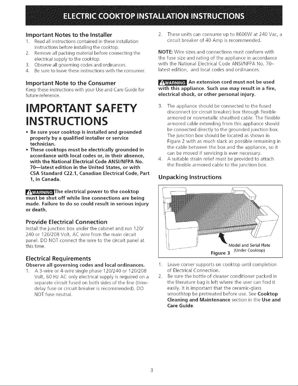
Unpacking Instructions
Model and Serial Plate
Figure 3 (Under Cooktop)
.
Leave corner supports on cooktop until completion
of Electrical Connection.
2.
Be sure the bottle of cleaner conditioner packed in
the literature bag is left where the user can find it
easily. It is important that the ceramic-glass
smoothtop be pretreated before use. See Cooktop
Cleaning and Maintenance section in the Use and
Care Guide.
EJectricaJ Connection
Connect the flexible armored cable that extends from
the surface unit to the junction box using a suitable
strain relief at the point the armored cable enters the
junction box. Then make the electrical connection as
follows.
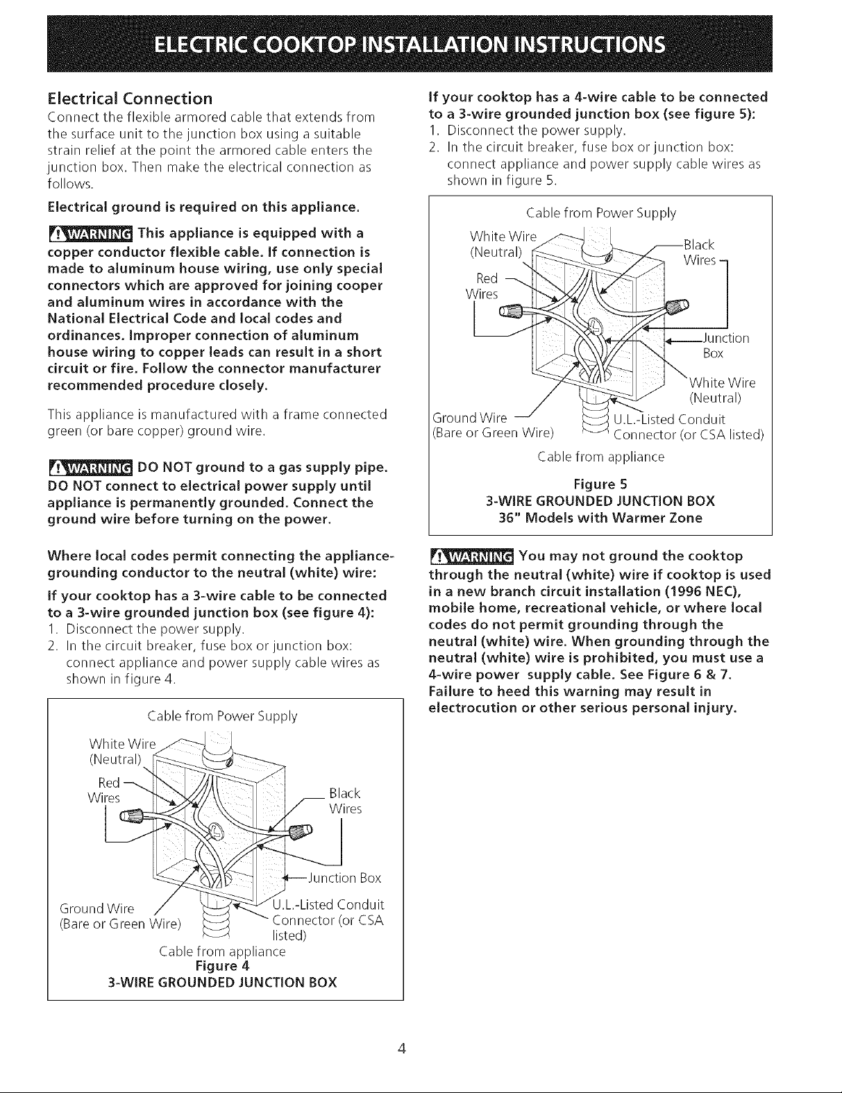
if your cooktop has a 4-wire cable to be connected
to a 3-wire grounded junction box (see figure 5):
1. Disconnect the power supply.
2. In the circuit breaker, fuse box or junction box:
connect appliance and power supply cable wires as
shown in figure 5.
Electrical ground is required on this appliance.
This appliance is equipped with a
copper conductor fJexibJe cabJe. Jf connection is
made to aJuminum house wiring, use onJy speciaJ
connectors which are approved for joining cooper
and aJuminum wires in accordance with the
NationaJ EJectricaJ Code and JocaJ codes and
ordinances, improper connection of aluminum
house wiring to copper leads can resuJt in a short
circuit or fire. FoJJow the connector manufacturer
recommended procedure closely.
This appliance is manufactured with a frame connected
green (or bare copper) ground wire.
DO NOT ground to a gas supply pipe.
DO NOT connect to eJectricaJ power suppJy untiJ
appJiance is permanentJy grounded. Connect the
ground wire before turning on the power.
Where IocaJ codes permit connecting the appJiance-
grounding conductor to the neutral (white) wire:
if your cooktop has a 3-wire cable to be connected
to a 3-wire grounded junction box (see figure 4):
I. Disconnect the power supply.
2. In the circuit breaker, fuse box or junction box:
connect appliance and power supply cable wires as
shown in figure 4.
Cable from Power Supply
Cable from Power Supply
White Wire
(Neutral)
Wires -
Red
Wires
Box
(Neutral)
Ground Wire U.L-Listed Conduit
Bare or Green Wire) _-onnector (or CSA listed)
Cable from appliance
Figure 5
3-WIRE GROUNDED JUNCTION BOX
36" Models with Warmer Zone
You may not ground the cooktop
through the neutral (white) wire if cooktop is used
in a new branch circuit installation (1996 NEC),
mobile home, recreational vehicle, or where local
codes do not permit grounding through the
neutral (white) wire. When grounding through the
neutraJ (white) wire is prohibited, you must use a
4-wire power supply cable. See Figure 6 & 7.
Failure to heed this warning may result in
electrocution or other serious personal injury.
Wh ite Wire
(Neutral)
Red---,,,
Wires
Black
Wires
Box
Ground Wire U.L-Listed Conduit
(Bare or Green Wire) Connector (or CSA
listed)
Cable from appliance
Figure 4
3-WIRE GROUNDED JUNCTION BOX

if cooktop is used in a new branch circuit
installation (1996 NEC), mobile home, recreational
vehicle, or where local codes DO NOT permit
grounding through the neutral (white) wire:
if your cooktop has a 3-wire cabJe (see figure 6):
I. Disconnect the power supply.
2. Separate the green (or bare copper) and white
appliance cable wires.
3. Cap the white wire from the power supply cable if a
3-wire appliance cable is supplied.
4. In the circuit breaker, fuse box or junction box:
connect appliance and power supply cable wires as
shown in figure 6.
Cable from Power Supply
Jf your cooktop has a 4 wire cable (see figure 7):
I. Disconnect the power supply.
2. Separate the green (or bare copper) and white
appliance cable wires.
3. In the circuit breaker, fuse box or junction box:
connect appliance and power supply cable wires as
shown in figure 7.
Cable from Power Supply
Ground Wire
Red
Wires
]
_ -White Wire
GrOURddWire_ ___...__ i
I _ ._-'/_'(' \_----------¢r/ _ Wires
L__ __u notion_ Box
Ground Wire / _ "_--_, U.L-Listed Conduit
(Bare or Green Wire) _ Connector (or CSA
listed)
Cable from appliance
Figure 6
4-WIRE GROUNDED JUNCTION BOX
Ground Wire
(Bare
Wire)
Conduit
Junction Box Connector (or CSA listed)
Cable from appliance
Figure 7
Models 36" with Warmer Zone
4-WIRE GROUNDED JUNCTION BOX
if connecting to a 4-wire power supply
cable electrical system, the appliance frame
connected ground wire MUST NOT be connected to
the neutral wire of the 4-wire electrical system.

Cooktop Installation
I. Visuallyinspectthecooktopfordamage.Alsomake
sureallcooktopscrewsaretight(seeFigure8).
Screws
Figure 8
2. Install the retainer brackets (See Figure 9).
6 Nylon
Figure 10
Checking Operation
Refer to the Use and Care Guide for operation.
_Do not touch cooktop glass or elements.
They may be hot enough to burn you.
The retainer brackets MUST be installed, to meet
local codes or, in their absence, with the National
Electrical Code ANSI/NFPA No. 70--latest edition, or
with CSA Standard C22.1, Canadian Electrical Code,
Part 1 (see Figure 9).
Cooktop Countertop
/Ion
spacer
8=18 x 3/8
Retainer bracket
Figure 9
Model and Serial Number Location
The serial plate is located under the cooktop.
When ordering parts for or making inquires about your
cooktop, always be sure to include the model and serial
numbers and a lot number or letter from the serial plate
on your cooktop.
Before You Call for Service
Read the Before You Call for Service Checklist and
operating instructions in your Use and Care Guide. It
may save you time and expense. The list includes
common occurrences that are not the result of defective
workmanship or materials in this appliance.
Refer to your Use and Care Guide for Sears service
phone numbers, or call 1-800-4-MY-HOME ®.
3. Set the cooktop into the countertop cutout.
NOTE: Do not use caulking compound; cooktop should
be removable for service when needed.
Do not remove the nylon spacers on
the edges of the cooktop. These spacers center the
cooktop in the space provided. The cooktop must
be centered to prevent excess heat buildup that
may result in heat damage or fire (see Figure 10).

LA INSTALACION Y EL SERVICIO DEBEN SER EFECTUADOS POR UN INSTALADOR CAUFICADO.
IMPORTANTE: GUARDE ESTASINSTRUCCIONES PARA USO DEL iNSPECTOR LOCAL DE ELECTRICIDAD.
LEA Y GUARDE ESTAS INSTRUCCIONES PARA REFERENCIA FUTURA.
PARA SU SEGURIDAD: No almanece ni utilice gasolina u otros vapores y liquidos inflamables en
la proximidad de este o de cualquier otto artefacto.
Dimensiones de la Estufa
30" Min. *
(76.2 cm) A/
Dimensiones del
Recortado de la Estufa
INFORMAClONIMPORTANTEPARALAINSTALAClON
* Todas las estufas el_ctricas funcionan con una
alimentaciOn el_ctrica con puesta a tierra de fase sin-
gular, 3 o 4 alambres, 240/208 voltios, 60 hertz y
s61oAC.
* Favor de notar que la distancia minima entre la
superficie de la estufa y los gabinetes adyacentes y
por encima son de 30" (76.2 cm).
* 30" (76.2 cm) rain. para un gabinete desprotegido.
24" (61 cm) rain. para una superficie protegida.
C
4"el x 8" (10.2 centimetros x 20.3
centimetros) apertura en la parte posterior
derecha para encaminar el cable armado
si un panel esta presente
G
Figura 1
iiiiiiiiiiiiiiii_i_i_i_i_i_ii!!!!!!}i_i¸i"i'i_i_i__!_!ii__i_iiiiiii_iiiiiiiiilliiii!!!!ii!i_i_iiiiiiiiiiiiiiiiiiiiiiiiiiiiiiiiiiiiiiiiiiiiiiiiiiiiiiiiiiiilliiiiiiiiiiiiiiiiiiiiiiiiiiiiiiiiiiiiiiiiiiiiiiiiiiiiiiiiiiiiiiiiiiiiiiiiiiiiiiii_i_iiiiiiilililiii¸¸¸1¸i!i!i!i!i!i!i!i!i!i!i!i!i!i!i!i!i!i!i!i!i!i!i!i!i!i!i!i!i!i!i¸iii¸i¸i¸ii_i_i_i_!i!!i!i!i!ii!i!_i_!i!i!i!!!ii_ii!ii!ii!ii!ii!ii!ii!il!ii!ii!ii!ii!ii!ii!_i_ii!i!i_iilililiii_¸i_i_ii_il!_i_!_!i!!i!!i!!i!!i!!i!!ii!_!!_!ii_iiliiilii!!ii!i!ii!ii!iiiiiiiiiiiiii_i_i_i_i_i_ii_ii_ii_ii_ii_ii_iiii!_!!_i!_i!_i!_i!_i!_i!_i!_i!_i!_i!_i!_i!_i!_ii_i!_il_i!_il_i!_i!_i_!i!i!i!i!iiiiiiiiliiiiiiiiiiiiiiiiiiiiiiiiiiiiiiiiiiiiiiiiiiiiiiiiii!!iiiiii!!i!_i!_i!iii!!!i!i!iiiiiiilliliiliiliiliiiiiliiliililili!!_'i_!i_i_i_iililii_i!_i@i!i@!ii_!!_!!_!!_!!_!_i!i!_!_!_!_ii:ii_ii_ii_iiiiiiiiiiiiiiiiiiiiiiiiiiiiiliiiiiiililiiiiiiiiiiiiiiiiiiiiiiiiiiiiiiiiiiiiiiiiiiiiiiiiiiiiiii_i_i_iiiiiii_i_ilililili!i!i!i_i!iilliiiiiiiili:!i:iii!ii!il!ii!ii!ii!,i!ii!ii!iililili!iiiiilliililiiiiiiii_i_iii!iiii!_ii_!i_!i_!i_i!_@i_iiiiiiiiii_iiiiiiiliiiiiiiiiiiiiiiiiiiiiiiiiiiiiiiiiiiiiiiiiiiiiiiiiiiiiiiii_i_i_i_i_i_ii!!!
iiiiiiiiiiiiiiiiiiiiiiiiiiiiiiiiiiiiii_i_i_i_i,i,i,lii_i_i_iiiililili!i!i_'i_!ii'_i_ili_!i!i!i!i!i!i!i!i!i!i!i!i!i!i!i!i!i!i!i!i!i!i!i!i!i!i!i!i!i!i!ii!!i!!!i_Ciiiiiiiii3,!_ii_i!_i_iii_!___ _________:i'i'i'i'i'i'i'i'i'i'i'i'i'i'i'i'i'i'i'i'i'i'i'i'!'!_'i_iiiiii_i!i!i!i!i!i!i!i!i!i!i!i!i!i!i!i!i!i!i!i!i!i!i!iiiii!ii!ii!ii!ii!_i_!i_!!:!:!:!:!:!:!:!:!:!:!:!:!:!:!:!:!:!:!:!:!:!:!:!:!:!!i!_ili!_i!i_i_!!_!_!_!_!_!_!_!_!_!_!_!_!_!_!_!_!_!_!_!_!_!_!_!_!_!_!_!_!_!_!_i!i!i!i!iiiiiiiiii@_'!!'_i!!!_'!_!i!i!i!i!i!i!i!i!i!i!i!i!i!i!i!i!i!i!i!i!i!i!!il_i!_i!_i!_i!_i!_i!_ii_ii_i_!_i_!_i!_i!_!i_!ii_i!_ii_i!_ii_i_ii_ii_ii!i_i_ii_i_!ii_ii_ii_ii_ii_ii_ii_ii_ii_ii_
Modelo30" 29s/s(75.2) 30(76.2) 20V_(51.4) 201/2(52.1) 6 (15.2)
Uodelo36" 35s/_(90.5) 36(91.4) 20V_(51.4) 20V2(52.1) 6 (15.2)
Todas las dimensiones se dan en pulgadas (cm).
* Deje 2" (5 cm) de hueco debajo de la estufa para espacio para el cable el@ctrico y la
instalaci6n de la caja de empalmes en la pared detr_is de la estufa.
Impreso en los Estados Unidos
P/N 318201439 (0607) Rev. B
English - pages 1-6
Espa_ol- pages 7-12

Elarmariosuperiornodebesobrepasaruna
profundidadm_qximade13"(33cm)
30"(76.2cm)min.de
espacioentrelaparte
superiordelfogony
laparteinferiordeun
armariodemaderao
metalsinprotecci6n.
A
k min. distancia
F----
recomendada entre el
horde trasero de[ corte y el
compartimiento de
combustible m_qscercano 10"
sobre ]a parte superior dd cm)
armario
J
24"(61cm)min.
cuandolaparteinferior
delarmariodemadera
ometalest,1protegida
porunaplaca
cortafuegoretardante
dellamadenomenos
de1/8",cubiertacon
unalaminadeacero
msgnoinferioralNo.
28,deaceroinoxidable
de0.015",aluminiode
0.024"ocobrede
0.020".
2 1/2" (6.4 cm) min. desde el borde delantero
del corte hasta el horde delantero de la parte
superior del armario
18"
(45.7cm)
F
Ubicaci6n' aproximada
de la caja de empalmes
J min. desde el
borde del corte
hasta el
compartimiento
de combustible
(ambos lados
del artefacto)
No es recomendable utilizar
cajones debajo de la estufa.
Para las dimensiones J y K, v@asela tabla en la pagina I.
Para evitar riesgos de
quemaduras o incendios al tocar superficies
calientes, se deben evitar los armarios sobre
lasuperficiedelosquemadores. Siexisteun
armario, se pueden reducir los riesgos
instalando una campana que se extienda
horizontalmente en un minimo de 5" (12.7
cm) por sobre la parte inferior de los
armarios.
Figura 2 - ELCORTE DE LA PARTE SUPERIOR DEL ARMARIO
Modelo 30" 7Y2"(19.1 cm)
l :M:
Modelo 36" 7Y2"(19.1cm)
2" (5.1 crn)
2" (5.1 cm)

Notas importantes para el instalador
I. Lea todas las instrucciones contenidas en este manual
antes de instalar la estufa.
2. Saque todo el material usado en el embalaje de la
estufa antes de conectar el suministro el6ctrico a la
estufa.
3. Observe todos los cOdigosy reglamentos pertinentes.
4. Deje estas instrucciones con el consumidor.
Nota importante al consumJdor
Conserve estas instrucciones y el Manual del usuario para
referencia futura.
INSTRUCCIONES
IMPORTANTES DE SEGURIDAD
• Aseg_rese de que su estufa sea instalada y puesta
a tierra de forma apropiada por un instalador
calificado o por un t&cnico de servicio.
• Esta estufa debe ser el&ctricamente puesta a tierra
de acuerdo con los c6digos locales o, en su
ausencia, con el C6digo El&ctrico National ANSI/
NFPA No. 70 - _ltima edici6n en los Estados
Unidos, o el C6digo El&ctrico Canadiense CSA
Standard C22.1, Part 1 en Canada.
La alimentaci6n el&ctrica a la estufa
deberJa apagarse mientras se hacen las conexiones
de lJnea. El no harcelo podrJa resultar en da_os
serios o la muerte.
NOTA: Eltamaho de los cables y de las conexiones debe
de estar en conformidad con el tamaho del fusible y con la
capacidad del electrodomestico y de acuerdo con el COdigo
El6ctrico Nacional ANSI/NFPANo. 70 - 01tima ediciOn y los
cOdigos y reglamentos locales.
No se debe usar una alargadora para
enchufar este electrodomestico. Esto podrJa resultar
en un incendio, un choque el_ctrico u otro tipo de
da_o personal.
3. Este electrodomestico debe conectarse a la caja de
fusibles (o de cortacircuitos), por medio de un cable
blindado flexible o un cable con forro no metalico. El
cable blindado flexible que va desde el
electrodomestico debe de estar conectado
directamente a la caja de empalme. La caja de
empalme debe de estar Iocalizada en el lugar que se
indica en la Figura 2, dejando tanto exceso de cable
como sea posible entre la caja y el electrodomestico,
de forma que asi el electrodomestico se pueda mover
facilmente, si fuera necesario para hacer una
reparaciOn.
4. Se debe de usar un conectador que reduzca la tirantez
de una forma adecuada para unir el cable blindado
flexible a la caja de empalme.
Instrucdones de desembalaje
Provea conexi6n el_ctrica
Instale la caja de empalmes debajo del armario y provea
un cable de 120/240 o 120/208 Voltios, AC al panel de
circuitos delaparato. NO conecte la cable al panel de
circuitos en este momento.
Requisitos eJectricos
Cumpla con todos los c6digos en vigor y todos los
reglamentos Iocales.
1. Para el suministro el6ctrico solamente se necesita
corriente con frecuencia de 60 Hz AC y fase 0nica de
120/240 o 120/208 voltios suministrada por cable de 3
o de 4 alambres en un circuito separado con fusibles
en ambos lados de la linea (serecomienda un fusible
de tiempo retardado o un cortacircuitos). NO ponga un
fusible en el hilo neutro.
2. Esta unidad puede consimir hasta 8600W a 240Vac, un
interruptor de40Amp esrecomendado.
Placa con los numeros de modelo y serie
(debajo de la cubierta)
Figura 3
.
Deje los soportes de las esquinas en la estufa hasta
la terminaciOn de la ConexiOn Electrica.
2.
Aseg0rese que la botella de limpiador ubicada en la
empaquete de literatura esta situada en un lugar
donde puede encontrarse fe_cilmente. Es importante
de tratar de antemano la superficie en vidrio de
ceramico antes de utilizar. Ve a la parte sobre
Limpieza y Mantenimiento de la Cubierta en
este Manual del usuario.

Conexi6n Electrica
Conecte el cable blindado flexible que se extiende desde la
superficie del artefacto hasta la caja de empalmes
utilizando una grapa de alivio de tensi6n adecuada en el
punto en que el cable blindado entra en la caja de
empalmes. Realizar luego la conexi6n el@ctrica de la
siguiente manera.
En este electrodomestico se necesita un cable de
puesta a tierra.
Este electrodom_stico viene equipado
con un cable de conexi6n de cobre. Si esto tuviera que
conectarse a los cables de aluminio de una casa, use
solamente los conectores especiales aprobados para
empalmes de cobre y aluminio, de acuerdo con el
C6digo El&ctrico National y los reglamentos y c6digos
locales. Una conexi6n incorrecta del alambrado de
aluminio con los conductores de cobre puede resultar
en un cortadrcuito o incendio.
Este electrodom@stico se fabrica con un alambre de puesta
a tierra verde (o de cobre sin forro) conectado con el
marco.
NO conecte el alambre puesto a tierra
a una tuberia de suministro de gas. NO conecte eJ
suministro de energ_a el_ctrica hasta que el
electrodomestico haya sido permanentemente puesto a
tierra. Conecte el alambre de puesto a tierra antes de
enchufar pot primera vez el electrodomestico.
Donde los c6digos locales permitan conectar el
conductor de puesta a tierra del el_ctrodom&stico al
neutral (bianco)
Si su cocina tiene un cable de 3 hilos que debe
conectarse a una caja de juntas con conexi6n a tierra de
3 hilos (ver figura 4):
1. Desconecte el suministroel_ctrico.
2. En el interruptor automatico, caja de fusibles o caja de
juntas: conectar el aparato y los cables residenciales
como se muestra en la figura 4.
Si su cocina tiene un cable de 4 hilos que debe
conectarse a una caja de juntas con conexi6n a tierra
de 3 hilos (ver figura 5):
1. Desconecte el suministro el_ctrico.
2. En el interruptor automatico, caja defusibles o caja de
juntas: conectar el aparato y los cables residenciales
como se muestra en la figura 5.
Cable desde el suministro de energia
Alambre
blanco (neutral) negros-
Alambre
de
empalmes
Alambre
blanco (neutral)
Alambre
verde o desnudo
Conductor de uni6n
listado-UL (o CSA)
Cable de la estufa
Figura 5- CAJA DE EMPALMES
DE 3 ALAMBRES PUESTA A TIERRA
Modelos 36" y un elemento del area calentadora
__ No podr_ conectar a tierra la cocina
a trav&s del cable neutral (bianco) si la cocina se usa
en una nueva instalaci6n de ramaJ de circuito (1996
NEC), en una casa rodante, en un vehiculo para
recreaci6n o si los c6digos locales no permiten
hacer la conexi6n a tierra a trav&s del cable neutral
(blanco). Cuando est_ prohibida la conexi6n a tierra
a trav&s del cable neutral (blanco), debe usar un
cable de aJimentaci6n de 4 hilos. Vet las Figuras 6 y
7. Si no observa esta precauci6n, puede sufrir
electrocuci6n u otra lesi6n personal grave.
Cable desde el suministro de energia
Alambre
blanco (neutra_[_ _____,__
Alambre _ _listado-UL (o CSA)
o desnudo Cable_de la estufa
vj_de _ Conductor deuni6n
Figura 4 - CAJA DE EMPALMES
DE 3 ALAMBRES PUESTA A TIERRA
empalmes
10

Si la cocina se usa en una instalaci6n nueva de ramal
de circuito (1996 NEC), en una casa rodante, en un
vehiculo para recreaci6n o si los c6digos locales NO
permiten hacer la conexi6n a tierra a trav&s del cable
neutral (blanco):
Si su cocina tiene un cable de 3 hilos (vet figura 6):
1. Desconecte el suministro el_ctrico.
2. Separe el alambre verde (o cobre desnudo) y el
alambre blanco del electrodomOstico.
3. Ponga un aislador en el alambre blanco del cable de
suministro si el aparato tiene un cable de sOlo 3
alambres.
4. En el interruptor automatico, caja de fusibles o caja de
juntas:conectar el aparato y los cables residenciales
como se muestra en la figura 6.
Cable desde el suministro de energia
Alambre
desnudo
Alambre
rojos
.Alambre blanco
Alambre
negros
de
empalmes
Si su cocina tiene un cable de 4 hilos (vet figura 7):
I. Desconecte el suministro el_ctrico.
2. Separe el alambre verde (o cobre desnudo) y el
alambre blanco del electrodomestico.
4. En el interruptor automatico, caja de fusibles o caja de
juntas:conectar el aparato y los cables residenciales
como semuestra en la figura 7.
Cable desde el suministro de energia
Alambre
Alambre
Red --
blanco
1
Alambre
Alambre
verde o
desnudo
Caja de
empalmes listado-UL (o CSA)
Cable de la estufa
Figure 7
CAJA DE EMPALMES
DE 4 ALAMBRES PUESTA A TIERRA
Modelos 36" y un elemento del area calentadora
Conductor de union
negros
Alambre verdeo Conductor de
desnudo uni6n listado-UL
(o CSA)
Cable de la estufa
Figura 6- CAJA DE EMPALMES
DE 4 ALAMBRES PUESTA A TIERRA
Si est_ conectado a un sistema
el6ctrico de 4 alambres, el armaz6n del
electrodom_stico NO TIENE QUE estar conectado al
alambre neutro del sistema el6ctrico de 4 alambres.
11

instaiadon de ia estufa
1.Visualmente inspecciones la estufa para daflos.
Verifique ademas que todos los tornillos de la estufa
est6n bien ajustados (Figura 8).
Tornillos
Figura 8
2. Instale las m_nsulas de sost_n. Vet Figura 9
Las m_nsulas de sostenimiento TENEN QUE
instalarse, a satisfacd6n de los c6digos locales o, en
su ausencia, con el C6digo El_ctrico Nacional ANSI/
NFPA No. 70--_ltima edici6n, o con la Norma CSA
C22.1, C6digo El_ctrico Canadiense, Parte 1 (Figura 9).
Estufa uperficie del amario
6 espaciadores
de nilOn
Figura 10
Revisi6n de operaci6n
Consulte el Manual del Usuario para las instrucciones
de funcionamiento.
No toque elcristaloloselementosdelaestufa. Puede
que est6n Io suficiente calientes para quemar.
Ubicad6n dei nemero de modeio y de serie
La plata con el nQmero de modelo y de serie esta
ubicada en el fondo de la estufa.
Cuando haga pedidos de repuestos o solicite informaci6n
con respecto a su estufa, este siempre segro de incluir el
n0mero de modelo y de serie y el n0mero o letra del Iote
de la plata de serie de su homo.
de nil6n
5/8
8-18 x 3/8
sonstenimiento
de
Figura 9
3.File la estufa en el recortado del armario.
NOTA: Noutilicecompuestoderetaque;laestufadebe
poder retirarse para las reparaciones cuando sea
necesario.
No quite los espaciadores de nil6n
en los bordes de la estufa. Estos espaciadores
mantienen la estufa en el centro del espacio
provisto. La estufa debe estar centrado para evitar
una acumulaci6n excesiva de calor que puede
resultar en da_os pot calor o incendio (Figura 10),
Antes de liamar al servicio
Lea la secci6n Lista de Control de Averias en su Manual
delUsuario. Estolepodraahorrartiempoygastos.
Esta lista incluye ocurrencias comunes que no son el
resultado de defectos de materiales o fabricaci6n de este
artefacto.
Lea la garantia y la informaci6n sobre el servicto en su
Manual del Usuario para obtener el n0mero de tel@fono
y la dirreci6n del servicio o Ilamar 1-888-SU-HOGAR sM.
12
 Loading...