

Kenmore 79040524400, 79041394402, 79041394403, 79041399401, 79041399402 Installation Guide
...Page 1
INSTALLATION AND SERVICE MUST BE PERFORMED BY A QUALIFIED INSTALLER.
IMPORTANT: SAVE FOR LOCAL ELECTRICAL INSPECTOR'S USE.
READ AND SAVE THESE INSTRUCTIONS FOR FUTURE REFERENCE.
FOR YOUR SAFETY: Do not store or use gasoline or other flammable vapors and Hquids in
the vicinity of this or any other appliance.
Your new wa[[ oven has been designed to fit a [imited variety of cutout sizes to make the job of installing
easier, The first step of your installation shouJd be to measure your current cutout dimensions and
compare them to the cutout dimensions chart below or next page for your mode[, You may find little or
no cabinet work will be necessary,
Do not remove spacers (if equipped) on the side walls and/or on the back of the built-in oven,
These spacers center the oven in the space provided. The oven must be centered to prevent excess heat buildup
that may result in heat damage or fire.
DO NOT INSTALL THIS WALL OVEN [N A BASE CABINET WITH A COUNTERTOP ABOVE IT.
NOTES:
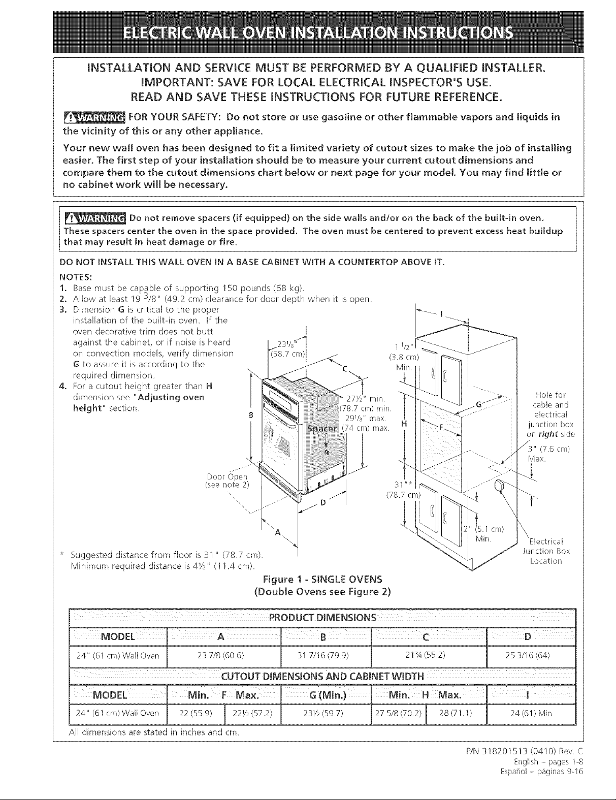
1. Base must be capable of supporting 150 pounds (68 kg)
2. Allow at least 19 3/8" (492 cm) clearance for door depth when it is open,
3. Dimension G is critical to the proper
installation of thebui[t-in oven. If the
oven decorative trim does not butt
against the cabinet, or if noise is heard
on convection models, verify dimension
G to assure it is according to the
required dimension.
4. For a cutout height greater than H
dimension see "Adjusting oven
height" section,
27Y/' rain.
B
78.7 cm) rain,
29Vs" max.
(74 crn) max.
1
Hole for
cable and
electrical
junction box
on right side
(7.6 cm)
Max.
* Suggested distance from floor is 31 " (78.7 cm) Junction Box
Minimum required distance is 4_z" (11.4 cm), Location
Figure 1 - SINGLE OVENS
(Double Ovens see Figure 2)
PRODUCTDIMENSIONS
MODEL ' A
24" (61 cm) Wall Oven 23 718 (60.6) 31 7116 (79.9) 21_A (55.2) 25 3116 (64}
CUTOUT DIMENSIONS AND CABINET WIDTH
(Min:) I Min: H
24" (61 cm) Wall Oven 22 (55.9) 22V2 (572)
All dimensions are stated in inches and cm,
23V2(59.7) 275/8(70.2) 28(711) 24 (61) Min
PIN 318201513 (0410) Rev C
English - pages 1-8
Espaflol - paginas 9-16
Page 2
Donotremovespacers(ifequipped)on the side walls and!or on the back of the built-in oven.
These spacers center the oven in the space provided, The oven must be centered to prevent excess heat
buildup that may result in heat damage or fire.
1//2 ''
Hole for cable and electrical
unction box on left or right
side depending on model,
3" (7.6 cm)
Max.
(S.1 c r)
Min,
depending on model)
NOTES
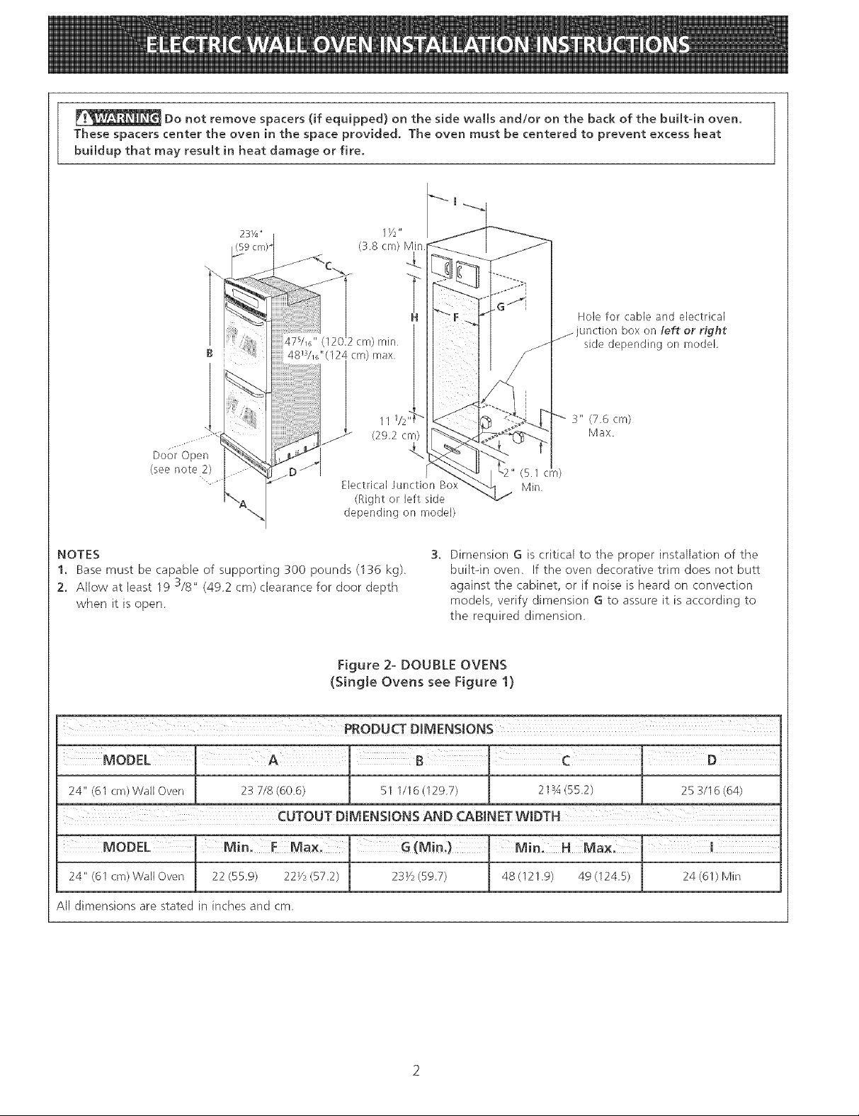
1. Base must be capable of supporting 300 pounds (136 kg),
2, Allow at least 19 3/8" (492 cm) clearance for door depth
when it is open
Dimension G is critical to the proper installation of the
built-in ovem If the oven decorative trim does not butt
against the cabinet, or if noise is heard on convection
models, verify dimension G to assure it is according to
the required dimension
Figure 2- DOUBLE OVENS
(Single Ovens see Figure 1)
_ PRODUCT DIMENSIONS
1¸ ' " ¸¸¸¸¸
24" (61 era)Wall Oven .[ 23 7/8(606) l 51 1/16(1297) 21_A(55.2) 253/16(64)
CUTOUT DIMENSIONS AND CABINET WIDTH
MODEL_ Min. F Ma _(Min;) s
24" <61crn) Wall Oven _ 22(559) 221/?(57.2) _ 231/?<597) j 48(121.9) 49<1245) 24<61)Min
All dimensions are stated in inches and cm
Page 3
Important Notes to the Installer
1. Read all instructions contained in these installation
instructions before installing the wall oven,
2. Remove all packing material from the oven
compartments before connecting tile electrical supply
to the wall oven,
3. Observe all governing (;odesand ordinances,
4. Be sure to leave these instructions with the consumer.
5. Oven door may be removed to facilitate installation.
6. THESE OVENS ARE NOT APPROVED FOR
STACKABLE OR SDE-BY-SIDE INSTALLATION.
Important Note to the Consumer
Keep these instructions with your Owner's Guide for future
reference.
IMPORTANT SAFETY
INSTRU S
• Be sure your watt oven is installed and grounded
properly by a qualified installer or service
technician.
• This walt oven must be eJectricaHy grounded in
accordance with local codes or, in their absence,
with the National Electrical Code ANSI/NFPA
No.70- latest edition in United States, or with CSA
Standard C22.1, Canadian Electrical Code, Part 1, in
Canada.
Stepping, leaning or sitting on the
door of this walt oven can resutt in serious injuries
and can also cause damage to the walt oven.
1. Carpentry
Refer to figure I or 2 for the dimensions applicable to
your appliance, and the space necessary to receive the
oven. The oven support surface may be solid plywood or
similar material, however the surface must be level from
side to side and front to rear.
2. Electrical Requirements
Theses appliances must be supplied with the proper
voltage and frequen(y, and connected to an individual,
properly grounded branch circuit, protected by a circuit
breaker or fuse, having amperage as noted on the rating
plate (the rating plate is located on the oven frame).
Observe aH governing codes and tocaJ ordinances
1. A 3-wire or 4-wire single phase 120/208 or 120/240
Volt, 60 Hz AC only electrical supply is required on
a separate circuit fused on both sides of the line
(time-delay fuse or circuit breaker is recommended).
DO NOT fuse neutral. The fuse size must not exceed
tile circuit rating of tile appliance specified on the
nameplate.
2. The single wall oven can consume up to 4000W at
240Vat; use a circuit breaker of 30 Amp with wire
gauge #8 AWG. The double wall oven can consume
up to 8000W at 240Vat; use a circuit breaker of 40
Amp with wire gauge #8 AWG.
NOTE: Wire sizes and connections must conform with
tile fuse size and rating of the appliance in accordance
with the American National Electrical Code ANSI/NFPA
No. 70qatest edition, or with Canadian CSA Standard
C22.1, Canadian Electrical Code, Part I, and local codes
and ordinances.
• Never use your wall oven for warming or heating
the room. Prolonged use of the wall oven without
adequate ventilation can be dangerous.
The electrical power to the oven must
be shut off while line connections are being made.
Failure to do so coutd resutt in serious injury or
death.
An extension cord should not be used
with this appliance. Such use may result in a fire,
electrical shock, or other personal injury.
3. These appliances should be connected to the fused
disconnect (or circuit breaker) box through flexible
armored or nonmetallic sheathed cable. Tile flexible
armored cable extending from the appliance should
be connected directly to tile junction box. The
junction box should be located as shown in figure 1
or 2 with as much slack as possible remaining in the
cable between the box and the appliance, so it can
be moved if servicing is ever necessary.
4. A suitable strain relief must be provided to attach
the flexible armored cable to the junction box.
Page 4
Electrical Shock Hazard
• Electrical ground is required on this appliance.
• Do not connect to the electrical supply until
appliance is permanently grounded.
• Disconnect power to the junction box before
making the electrical connection.
• This appliance must be connected to a
grounded, metallic, permanent wiring system,
or a grounding connector should be connected
to the grounding terminal or wire lead on the
app[[anceo
• Do not use a gas supply line for grounding the
appliance.
Failure to do any of the above could result in a
fire, personal injury or electrical shock.
In cold weather shipping and storage
conditions, make sure that oven is in final location at
least three (3) hours before switching on power.
Switching on power while oven is still cold may damage
the oven controls.
3. Adjusting Oven Height
Remove and lay aside the lower vent decorative trim
that is taped to the outer side panel of the oven. The
decorative trim will be fastened to tile lower front of
the oven after it has been installed in the cabinet.
There is a 13A'' (4.4 cm) height adjustment on models
with extension panel (see figure 3). With this
adjustment and a Y4" (0.6 cm) trim overhang, a single
oven can be installed in existing openings 27SA" (70.2
cm) to 29sA" (75.2 cm) or a double oven in existing
openings 48" (121.9 cm) to 50" or 49 7/8" (! 27 cm or
126.7 cm) high.
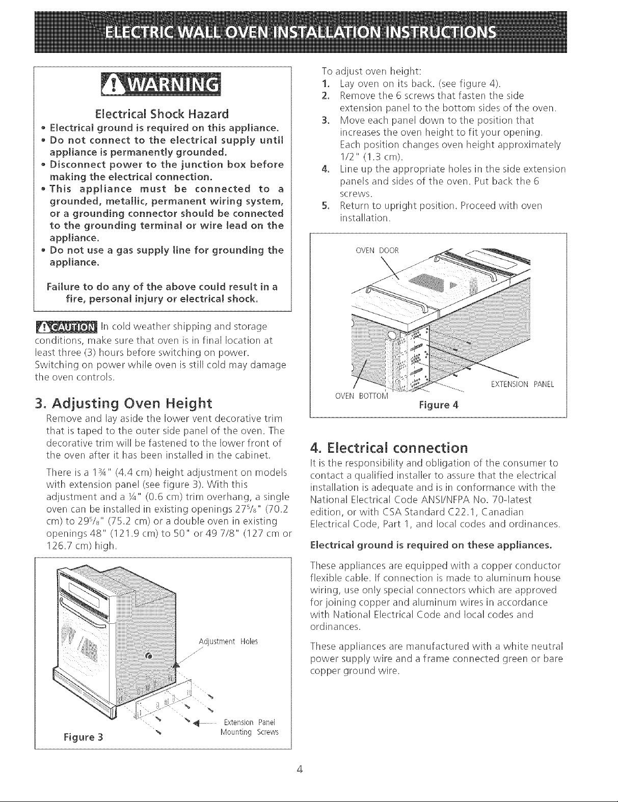
To adjust oven height:
1. Lay oven on its back. (see figure 4).
2. Remove the 6 screws that fasten the side
extension panel to the bottom sides of the oven.
3. Move each panel down to the position that
increases the oven height to fit your opening.
Each position changes oven height approximately
1/2" (1.3 cm).
4. Line up the appropriate holes in the side extension
panels and sides of tile oven. Put back the 6
screws.
5. Return to upright position. Proceed with oven
installation.
OVEN DOOR
J
EXTENSION PANEL
OVEN BOTTOM
Figure 4
4. Electrical connection
It is the responsibility and obligation of the consumer to
contact a qualified installer to assure that the electrical
installation is adequate and is in conformance with the
National Electrical Code ANS!/NFPA No. 70qatest
edition, or with CSA Standard C22.1, Canadian
Electrical Code, Part 1, and local codes and ordinances.
Electrical ground is required on these appliances.
Figure 3
Adjustment HoLes
/
% %
% % _ Extension Panel
Mounting Screws
These appliances are equipped with a copper conductor
flexible cable. If connection is made to aluminum house
wiring, use only special connectors which are approved
for joining copper and aluminum wires in accordance
with National Electrical Code and local codes and
ordinances.
These appliances are manufactured with a white neutral
power supply wire and a frame connected green or bare
copper ground wire.
Page 5
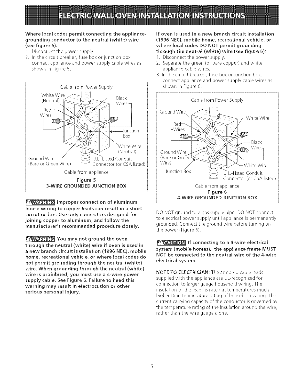
Wherelocalcodes permit connecting the appliance-
grounding conductor to the neutraJ (white) wire
(see figure S}:
1. Disconnect the power supply.
2. In the circuit breaker, fuse box or junction box:
connect appliance and power supply cable wires as
shown in Figure 5.
Cable from Power Supply
White Wire
(Neutral)
Red
Wires
Wires
if oven is used in a new branch circuit installation
(!996 NEC), mobile home, recreationaJ vehicle, or
where local codes DO NOT permit grounding
through the neutral (white) wire (see figure 6}:
1. Disconnect the power supply.
2. Separate the green (or bare copper) and white
appliance cable wires.
3. In the circuit breaker, fuse box or junction box:
connect appliance and power supply cable wires as
shown in Figure 6.
Cable from Power Supply
Ground Wire
Wire
Box
(Neutral)
Ground Wire U.L.-Listed Conduit
(Bare or Green Wire) Connector (or CSA listed)
Cable from appliance
Figure 5
3-WtRE GROUNDED JUNCTION BOX
Improper connection of atuminum
house wiring to copper leads can result in a short
circuit or fire. Use onty connectors designed for
joining copper to aluminum, and follow the
manufacturer's recommended procedure closely.
You may not ground the oven
through the neutra! (white} wire if oven is used in
a new branch circuit installation (!996 NEC), mobile
home, recreational vehicle, or where local codes do
not permit grounding through the neutral (white}
wire. When grounding through the neutraJ (white}
wire is prohibited, you must use a 4-wire power
supply cable. See Figure 6. Failure to heed this
warning may resuJt in electrocution or other
serious personat injury.
Wires
Black
Ground Wire
(Bare or
Wire)
Junction Box
U.L.-Listed Conduit
Connector (or CSA listed)
Cable from appliance
Figure 6
4-WIRE GROUNDED JUNCTION BOX
DO NOT ground to a gas supply pipe. DO NOT connect
to electrical power supply until appliance is permanently
grounded. Connect the ground wire before turning on
the power (Figure 6).
If connecting to a 4-wire electrical
system (mobile homes}, the appliance frame MUST
NOT be connected to the neutral wire of the 4-wire
electrical system.
NOTE TO ELECTRICIAN: The armored (:able leads
supplied with the appliance are UL-recognized for
connection to larger gauge household wiring. Tile
insulation of the leads is rated at temperatures much
higher than temperature rating of household wiring. The
current carrying capacity of the conductor is governed by
the temperature rating of the insulation around the wire,
rather than tile wire gauge alone.
Page 6

HeavyWeightHazard
• Use2or morepeopleto moveand installwatt
oven.
• Failure to follow this instruction can resuJt in
injury or damage to the unit,
5. Cabinet Installation
The wall oven can tip when the door
is open. The mounting screws supplied with the
wall oven must be attached to the cabinet and the
appJiance to prevent tipping of the wall oven and
injury to persons.
IMPORTANT
Do not lift the oven by the door handle.
Single and Double Ovens
Insert appliance into cutout. Use the screws provided to
fasten the front frame of the appliance to the cabinet.
The mounting holes in the front frame of appliance may
be used as a template to determine the location of the
mounting holes in the cabinet.
To fasten the appliance to the cabinet:
1. Line up the 2 mounting holes on the decorative trim
(ventilation) (taped to the oven side panel) with the
lower mounting holes on each side of tile oven frame,
below the oven door (see figure 7).
2. Use2 screws from the miscellaneous parts bag to
secure the decorative trim (ventilation) and appliance
to the cabinetry.
3. Usethe remaining 2 screws for mounting tile
appliance in the upper two mounting holes on each
side of the oven frame, above the door.
Mounting
Screw
1
Decorative
Trim
_/
Screw
L
Fi ure 7
Page 7

5. Leveling the Wail Oven
1. Install an oven rack in the center of the upper oven
(see Figure 9).
2. Place a level on the rack. Take 2 readings with the
level placed diagonally in one direction and then the
other. Usewood shims under tile wall oven to level
if necessary.
3. Repeat in the lower oven if you have a double cavity
wall oven. If the level indicates that tile rack is not
level, use wood shims to reach a compromise for
both ovens.
Figure 9
7. Checking Operation
Your model is equipped with an Electronic Oven
Control. Each of the functions has been factory checked
before shipping. However, it is suggested that you verify
the operation of the electronic oven controls once more.
Refer to the Use and Care Guide for operation.
Clean (some modeJs)-When the oven is set for a self-
cleaning cycle, the upper element should become red
during the preheat portion of the cycle. After reaching
the self<leaning temperature, tile lower element will
become red.
IMPORTANT NOTE: A fan inside the upper rear part
above the oven (some models) provides additional
cooling of the oven electrical and electronic components.
The fan will continue to run after the oven has been
operating at high temperatures.
Model and Serial Number Location
The serial plate is located along the side trim of the oven
and visible when the door is opened.
When ordering parts for or making inquires about your
oven, always be sure to include the model and serial
numbers and a lot number or letter from the serial plate
on your oven.
Before You Call for Service
Read the Before You Call for Service Checklist and
operating instructions in your Use and Care Guide. It
may save you time and expense. The list includes
common occurrences that are not the result of defective
workmanship or materials in this appliance.
Refer to your Use and Care Guide for Sears service
phone numbers, or call 1-800-4-MY-HOME_L
1. Remove all items from the inside of the oven.
2. Turn on the power to the oven (refer to your Use &
Care Guide).
3. Verify the operation of the electronic oven controls:
Bake-After setting the oven to 350%/177°C for baking,
tile lower element in the oven should become red.
BroiPWhen the oven is set to BROIL,the upper element
in the oven should become red.
Page 8

Notes
Page 9

LA mNSTALACmON Y EL SERVmCmODEBE DE HACERLOS UN mNSTALADOR CAMNCADO.
mMPORTANTE: GUARDE ESTAS mNSTRUCCmONES PARA USO DEL mNSPECTOR ELECTRmCO LOCAL.
LEA Y GUARDE ESTAS mNSTRUCCmONES PARA FUTURAS REFERENCmAS.
PARA SU SEGURmDAD: No a[macene nJ uti[ice gaso[ina u otros vapores y [[quidos inflamab[es
en [a proximidad de este o de cua[quier otto artefacto.
Su nuevo homo de pared ha sido dJsehado para adaptarse a un numero diverso de huecos con dist[ntas
medidas, y hater e[ trabajo de JnstaJacJ6n rnas fac[[. E[ primer paso para su insta[acion debe de set e[ de medir
[as dimens[ones de [a apertura actual y comparar[as con [as que se indJcan en e[ cuadro de dimensiones de[
hueco en e[ grafico a cont[nuaci6n, para su mode[o. Puede ocurrir que no sea cas[ necesario hacer trabajo de
carpJnterJa.
No quite los separadores (si los hay) de los muros [atera[es o/y de [a parte posterior de[ homo
emportado. Estos espaciadores centran e[ homo en e[ espacio provisto. E[homo debe estar centrado para prevenir una
eoncentraei6n excesiva de ca[or que podria resu[tar en dahos pot e[ ca[or o un incendio.
NO [NSTALE ESTEHORNO 24" EN LA PARTE DEABAJO DE UN ARMAR[O DE GOG[NA QUE T[ENE UN MOSTRADOR ENG[MA.
NOTAS
1, La basa debe poder sostener 150 [ibras (68 kg.)
2, Deje por Io menos 19 3/8" (49.2 cm) de espacio libre para [a
profundidad de [a puerta cuando esta abierta.
3, La dimension G est#_ primordial para instalar
correctamente el homo de pared, Si el ador-
no del armazon del homo no topa contra el
armario, o si escuche un ruido, verifique si la
dimension G esta en conformidad con la dP M
mension requerida.
4, Para un recortado con altura de mS_sde H
dimension vea "Ajustando la Altura del
Horno" seccion. B
Puerta Abiert
/yea la nora 2) i 31 "'
1
27_/2" rnin, Actujero a la
2%/s" max, H cable y la caja de
i_ (78,7 crn)
(3,8 cm)
Min,
cm) rain derecha para el
max, ernpalme electrica
/
3" (7,6 cm) Max,
4
Distancia sugerida desde el sue[o es 31 " (78,7 cm).
La distancia minima requerida es 4Y_" (11.4 cm).
Figura 1- MODELOS CON UN SOLO HORNO
(Mode[os de homo dome vea ta Figura 2)
DINIENSIO@ESDELAPARATO
Homo de pared 24" (61 cm) 23 7/8 (60,6) 31 7/16 (799) 21:/4(55,2) 25 3/16 (64)
DIMENSIONES DEL HUECO Y ANCHURA DEL ARNIAR[O
Min. F Max. G(Min.) Min. H Max. '
Homo de pared 24" (61 crn) 22 (559) 22_/¢(57,2) 23_/¢(597) 27 5/8 (70,2) 28 (71,1) 24 (61)Min
Todas las dimensiones se dan en pulgadas (cm),
P/N 318201513 (0410) Rev. C
Espaflol pagin_s 9 16
de ernpalme
electrica
English pactes 1 8
Page 10

Noquitemosseparadores(simoshay)delosmurosmaterameso/yde[aparteposteriorde[homo
emportado,Estosespaciadores centran emhomo en emespacio provisto. Emhomo debe estar centrado para prevenir
una concentraci6n excesiva de camor que podria resumtar en daffos pot emcalor o un incendio.
B
r........;iii!
Puerta Abl_rt_
(yea la nora)
(a la derecha o a I_
"_ izquierda segOn el modelo)
NOTAS:
1, La basa debe poder sosLener 300 libras (136 kg.)
2. Deje por Io menos 19 3/8" (49.2 cm) de espacio libre para
la prorundidad de la puerta cuando esta abierta.
Figura 2 oMODELOS CON UN HORNO DOBLE
(Modetos con un soto homo vea ta Figure 1)
DIMENSIONES DEL APARATO
Cable (a la derecha o a la
On el modelo)
(76 cm)
Max,
(5/I cm)
Min,
3. La dimension G est_ primordial para instalar correc[amente el
homo de pared, Si el adorno del armazon del homo no topa
contra el armario, o si escuche un ruido, verifique si la dimen-
sion G esLa en conformidad con la dimension requerida.
MODELO A B C
Horno de pared24" (61 cm)L 23 7/8 (60,6) 51 1/1_-i(1297) 1 21:"4 (55,2) [ 25 3/16 ((}4)
Horno de pared 24"
Todas las dimensiones se dan en pulgadas (cm).
(61cm) 22(S5,9) 22_/,(S72) 23X,(597) _ 48(121,9) 49(124,5) _ 24(61)Min
F F
/ /
10
Page 11

Notas importantes para e[ insta[ador
1. Lea todas las instrucciones contenidas en este manual
antes de instalar el homo,
2, Saque todo el material usado en el embalaje del
compartimiento del horno antesde conectar el suministro
electrico o de gas a la estufa,
3, Observe todos loscodigos y reglamentos pertinentes,
4, Deje estas instrucciones con el consumidor,
5, La puerta del horno se puede quitar para facilitar la
instalaciOn.
6. ESTEHORNO NO ESTA APROBADO PARA LA
INSTALACION DE RIMERO O DA LADO A LADO.
Nota importante al consumidor
Conserve estas instrucciones y el manual del usuario para
referencia futura.
IMPORTANTES DE SEGUR[DAD
• Asegurese de que su homo a pared sea instalada y
puesta a Nerra de forma apropiada pot un
instaJador ca[ificado o pot un tecnico de servicio.
° Este homo de pared debe set electricamente
puesta a tierra de acuerdo con Jos cddigos Joca[es
o, en su ausencia, con et Cddigo E[ectrico National
ANSI/NFPA No. 70-Qltima edicidn en los Estados
Unidos, o e[ Codigo EJectrico Canadiense CSA
Standard C22.1, Part 1, en Canad4.
2. Requisitos El6ctricos
Este artefacto debe ser suministrado con el voltaje y la
frecuencia adecuados, y conectado a un circuito
individual correctamente puesto a tierra, protegido por
un cortacircuito o un fusible con el amperio anotado en
la plata de calificaciOn (la plata se encuentra en el
armazon del homo),
Cumpla con todos los cddigos en vigor y todos los re-
gJamentos JocaJes.
1, Parael suministro electrico solamente se necesita
corriente con frecuencia de 60 Hz AC y fase 0nica de
120/208 o 120/240 voltios suministrada por cable de 3 o
de 4 alambres en un circuito separado con fusibles en
ambos lados de la linea (serecomienda un fusible de
tiempo retardado o un cortacircuito), NO ponga un
fusible en el hilo neutro, Eltamarlo del fusible no tiene
que exceder la capacidad del circuito necesario para el
electrodomesticos y la cual se especifica en la placa,
2. Elhorno simple de pared puede consumir un maximo de
4000W a 240Vac, Useun disyuntor de 30 amperes con
un cable #8 AWG, El homo doble de pared puede
consumir un maximo de 8000W a 240Vac, Useun
disyuntor de 40 amperes con un cable #8 AWG,
NOTA: Eltamano de loscables y de las conexiones debe
de estar en conformidad con el tamano del fusible y con la
capacidad del electrodomesticos y de acuerdo con el
Codigo Electrico Nacional ANSI/NFPANo. 70 - t]ltima
edicion, o el Codigo Electrico Canadiense CSA Standard
C22,1, Part 1, y los codigos y reglamentos locales.
Pisar, apoyarse, o sentarse sobre ta
puerta de este homo a pared puede resu[tar en
serias Jesiones y tambien puede causar daffos a[
homo a pared.
° Nunca use su homo a pared para calentar et
cuarto. El uso prolongado de la estufa sin la
ventilacion adecuada puede ser peligroso,
La corriente electrica a[ homo debe
estar apagada mientras se hacen las conexiones de
tineas, Si no se apaga, daffos serios o ta muerte
podrian resuItar.
1. CarpinterJa
Consulte lasFiguras 1 y 2 para conocer las dimensiones
pertinentes al modelo de su horno y al espacio necesario
en el que poner el homo. La superficie donde se va a
apoyar el homo debe de ser de madera contrachapada
solida u otro material similar y. sobre todo, la superficie
tiene que estar a nivel, de lado a lado, y de arras hacia
adelante,
No se debe usar una alargadora para
enchufar este e[ectrodomestico. Esto podria
resultar en un incendio, un choque electrico u otto
tipo de daho personal.
3, Esteelectrodomestico debe conectarse a la caja de
fusibles (ode cortacircuito), por medio de un cable
blindado flexible o un cable con forro no metalico, El
cable blindado flexible que va desde el electrodome,stico
debe de estar conectado directamente a la caja de
empalme, La caja de empalme debe de estar Iocalizada
en el lugar que se indica en la Figura 1 o 2, dejando
tanto exceso de cable como sea posiMe entre la caja y
el electrodomestico, de forma que asi el electrodomesti-
co se pueda mover facilmente, si fuera necesario para
hacer una reparaciOn,
4, Se debe de usar un conectador que reduzca la tirantez
de una forma adecuada para unir el cable blindado
flexible a la ca]a de empalme,
11
Page 12

Riesgo de choque ÷[ectrico
, Una puesta a tierra se require en este aparato.
No [o conecte a [a corriente e[ectrico hasta que
et aparato haya sido puesto a tierra.
. Desconecte [a corriente et6ctrica a [a caja de
empalmes antes de hacer la conexion el6ctrica.
Este aparato debe estar conectado con un
sistema de ahmbres puesto en tierra, metamico
y permanente o un conector de pueta a tierre
debe conectarse a[ terminal de puesta a tierra
o e[ a[ambre conductor en al aparato.
No utHice el suministro de gas para hacer [a
puesta a tierra.
La fa[ta de hater cualquier de [as cosas arriba
podr[a resultar en un incendio, choque e[6ctrico
o [esiones persona[es.
Cuando utilice su horno empotrado por la
primera vez, espere por Io menos tres (3) horas antes de
conectarlo al suministro electrico. Los controles electricos
pueden ser danados al conectar el homo a la potencia
electrica.
Para ajustar la altura del horno:
1. Ponga el horno apoyado en la pare trasera, (yea la
figura 4)
2. Quite los 6 tornillos que sujetan el panel de extension
lateral a la parte inferior de los lados del homo,
3. Mueva cada parle[ hacia abajo, hasta [aposici0n que
aumenta [aaitura de[ horno para que seadapte a la
apertura que ustedtiene. Cadaposicioncambia [aaltura
de[homo 1/2 pulgada(1.3cm) aproximadamente.
4. Alinee losagujeros apropiados en los paneles de
extension yen los lados del homo, Vuelva a poner
los 6tornillos.
5. Proceda con la instalacion del homo, Vuelva a poner
el homo en posicion vertical posiciOn,
PUERTADEL
HORNO
3. Ajustando la Altura del Homo
Retire y deje a un lado la rejilla que esta sujeta con cinta
adhesiva al panel exterior del homo, Esta rejilla se
sujetara a la parte baja frontal del homo, despues de
que este se haya instalado en el armario,
En estos modelos hay 1:Y4"(4,5 cm) de ajuste en la
altura (yea la figura .3). Con este ajuste y Y4" (0,6 cm)
del horde que sobresale, el electrodomestico puede
instalarse en huecos de 27s/s" (70,2 cm) a 29%" (75,4
cm) (para horno sencillo) o de 48" (121.9 cm) a 50"
(127 cm) o 49 7/8" (126.7 cm) de alto (para homo
doble).
. Agujeros de ajuste
/
/-
./
PANELDE
PARTEDE ABA/O
[)EL HORNO
Figura 4
EXTENSION
4. Conexi6n eJectrica
El usuario tiene la responsabilidad personal y obligacion
de utilizar un instalador calificado, para asegurar que la
instalacion electrica esta hacha de forma adecuada y
esta conforme con el Codigo Electrico Nacional ANSI/
NFPA No. 704]ltima edicion en los Estados Unidos, o el
Codigo Electrico Canadiense CSA Standard C22.1, Part
1, en Canada.
En este e[ectrodomestico se necesita un cable de
toma a tierra.
Este electrodomestico viene equipado con un cable de
conexion de cobre. Si esto tuviera que conectarse a los
cables de aluminio de una casa, use solamente los
conectados especiales aprobados para empalmes de
cobre y aluminio, de acuerdo con el Codigo Electrico
Nacional y los reglamentos y codigos locales.
_ TorniNos de montaje
para al de extension
Figura 3
Este electrodomestico se ha fabricado con un cable para
el suministro de energJa que tiene un alambre neutro de
color blanco y un alambre pelado de toma a tierra
conectado al armazOn,
12
Page 13

Donde los codigos Joca[es perrnitan conectar e[
conductor de puesta a tierra de[ e[6ctrodomestico a[
neutral (bJanco) (yea figura 5):
1, Desconecte el suministro ebctrico,
2, Enel interruptor automatic-o, caja de fusibles o caja de
juntas: conectar el aparato y los cables residenciales
como se muestra en lafigura 5,
Cable desde el suministro de energla
Alambre
desnudc.!l_ /-_-_._ M/_ Alarnbre
...-"_,,_v{/_.__ Wb.\ ernpalines
:_/-_/A_ ] j "- Alambre
Alambre verde/// __._ desnudo
o desnudo--I __tuctor de
union listado-UL
(o CSA)
Cable de la estufa
Figura 5 oCAJA DE EMPALMES
DE 3 ALAMBRES PUESTA A TIERRA
Una cone×i6n incorrecta de[
a[ambrado de a[uminio con los conductores de cobre
puede resultar en un cortacircuito o incendio. Use
soJamente tos conectores diseffados parajuntar eJ
cobre con et aJuminio y siga exactamente e[
procedimiento recomendado pot e[ fabricante.
No se puede conectar a tierra e[
homo a traves de[ cabJe neutral (bJanco) si e[ homo
es usado en una insta[aci6n de circuito de ramaJ
nuevo (1996 NEC), en una casa rodante, en un
veh[cu[o para recreaci6n o si los c6digos [oca[es no
permiten [a cone×ion a tierra a traves de[ cable
neutral (bJanco). Si esta prohibida [a conexi6n a
tierra a traves de[ cable neutral (bJanco), se debe
usar un cable de a[imentacion de 4 hi[os. Vet [a
Figura 6. Si no se observa esta advertencia, esto
puede resu[tar en e[ectrocuci6n o en otra lesion
persona[ grave.
Si el horno se usa en una instalacion de circuito de
ramal nuevo (1996 NEC), en una casa rodante, en un
vehiculo para recreacion o si los codigos locales NO
permiten la conexion a tierra a traves del cable
neutral (blanco) (ver figura 6):
1. Desconecte elsuministro elex;trico
2. Separe el alambre verde (ocobre desnudo) y el
alambre blanco del electrodomestico.
3. En el interruptor automatico, caja de fusibles o caja de
juntas:conectar el aparato y loscables residenciales
como se muestra en la figura 6.
Cable desde el suministro de energla
_--_-_._ Alambre blanco
Alambre
empalmes
"" Conductor de union
listado-UL (o CSA)
Cable de la estufa
Figura 6- CAJA DE EMPALMES
DE 4 ALAMBRES PUESTA A TIERRA
NO conecte el alambre puesto a tierra a una tuberla de
suministro de gas, NO conecte el suministro de energla
electrica hasta que el electrodomestico haya sido
permanentemente puesto a tierra. Conecte el alambre de
puesto a tierra antes de enchufar por primera vez el
electrodomestico.
Si esta conectado a un
sistema
eJectrico de 4 a[ambres, et armazon de[
e[ectrodomestico NO TIENE QUE estar conectado al
a[ambre neutro de[ sistema e[ectrico de 4 a[ambres.
NOTA AL ELECTRICISTA: Losconductores de cable
blindados provistos con este artefacto son aprobados por
UL para la conexion al alambrado de casa de un calibre
mayor. El aislamiento de los conductores esta calificado
para temperaturas mas altas que las del alambrado de la
casa. Lacapacidaddecorrientedelconductoresta
gobernada por la calificacion de la temperatura del
aislamiento alrededor del alambre en vez de solamente
el calibre del alambre.
13
Page 14

Peligro de Peso Pesado
o Use 2 [sersonas o mas [sara mover e insta[ar e[ homo
de [sared.
oSi no cum[s[e con esta instruccJdn, [suede resu[tar
en [es[ones [sesona[es o dahos a[ homo de [sared
5, [nstaiaci6n de[ Gabinete
E[ homo de pared [suede [nc[inarse
cuando [a [suerta esta ab[erta. Las toinHios anti
[nc[inac[6n que v[enen con e[ homo de pared deben
de estar ajustadas a[ armar[o y a[ a[sarato [sara
ev[tar que e[ homo de pared se incline y ocas[one
quemaduras graves.
Para f[jar e! artefacto a los gabinetes:
1. Alinee los dos agujeros de montadura en la parrilla
con los agujeros de montadura mas bajos en cada
lado del armazon del horno debajo de la puerta del
horno (Figura 7).
2, Use dos tornillos de la bolsa de piezas miscelaneas
para fijar la parrilla y el artefacto a los gabinetes,
& Use los 2 tornillos restantes en los 2 agujeros de
montadura arriba en cada lado del armazon del
homo, encima de la puerta,
Tornillos de
R]ontadura
No [evante e[ homo por [a man_a de [a puerta.
iMPORTANTE l
Mode[os con un sob homo y un homo
dob[e
Introduzca el artefacto en el recortado, Los tornillos
estan provistos para fijar el armazon frontal del artefacto
algabinete, Losagujerosdemontaduraenelarmazon
frontal pueden usarse como modelo para Iocalizar los
agujeros para los tornillos de montadura del artefacto,
Figura 7
Parilla
repirader _
inferior
. Tornillos de
rnor/tadura
14
Page 15

6. Asegurese de que el homo de
pared esta a hive[
1. Instale una rejilla al centro del horno superior (yea la
Figura 9).
2, Ponga un nivel por encima de larejilla. Lea2 veces, una
vez con el nivel a la position de lado a lado, y otra vez
de atras hacia adelante. Utilice trozo de madera o cu-
fias por debajo del homo de pared para nivelar, si sea
necesario,
3, Vuelve a empezar en el homo inferior, Si el nivel mues-
tra que la rejilla no esta a nivel, utilice trozo de madera
o cunas para componer ambos hornos,
Asar- Cuando se pone el homo para asar, el elemento de
arriba del horno debe de ponerse rojo.
Limpieza (algunos mode!os)_ Cuando el horno se pone
en el ciclo para que se limpia a si mismo, el elemento de
arriba debe de ponerse rojo durante la parte de pre-
calentamiento del ciclo de limpieza. Despues de que
Ilegue a la temperatura adecuada de limpieza, el
elemento de calentamiento inferior se encendera y debe
de ponerse rojo.
NOTA IMPORTANTE: Algunos modelos tienen un
ventilador pequeno situado dentro del panel de control
para enfriamiento adicional de los componentes
electricos y electr0nicos, El ventilador continuara
funcionando despues de que el homo haya estado
operando a una temperatura alta, como a la que se
Ilega cuando el homo se esta limpiando,
Ubicacion del numero de modelo y de serie
La placa con el numero de modelo y de serie esta
ubicada en el borde de la puerta del homo en la
posicion abierta.
Cuando haga pedidos de repuestos o solicite informacion
con respecto a su homo, este siempre seguro de incluir
el n0mero de modelo y de serie y el n0mero o letra del
Iote de la placa de serie de su homo.
7. Verification de del
funcionamiento
Su modelo esta equipado con un Control Electronico de
Homo. Cada una de las funciones ha sido controlada en
fabrica antes del despacho. Sin embargo, le sugerimos
verificar elfuncionamiento de los controles electronicos
una vez mas. Consulte la Guia de Uso y Cuidado para
ver el funcionamiento del homo.
1. Extraer todos los elementos de la parte interior del
homo.
2.Encender el horno (Consular la Guia de Uso y Cuidado.)
3.Verificar el funcionamiento de los controles electronicos
del horno:
Hornear- Bespues de poner el horno a 350' F/177'C para
hornear, el elemento de la parte de abajo del homo se
debe de ponerse rojo.
Antes de liamar al servicio
Lea la seccion Lista de Antes de Ilamar en su Manual del
Usuario. Estolepodraahorrartiempoygastos. Esta
lista incluye ocurrencias comunes que no son el resultado
de defectos de materiales o fabricaci0n de este
artefacto.
Lea la garant[a y la informaciOn sobre el servicio en su
Manual de! Usuario para obtener el numero de
telefono gratuito y la direccion del servicio o llama
1o888oSUoHOGARsM.
15
Page 16

Notas
16
 Loading...