

Kenmore 79033043401, 79033043400 Installation Guide
INSTALLATION AND SERVICE MUST BE PERFORMED BY
A QUAUHED INSTALLER.
IMPORTANT: SAVE FOR LOCAL ELECTRICAL INSPECTOR'S USE.
READ AND SAVE THESE INSTRUCTIONS FOR FUTURE REFERENCE.
[f the information in this manual is not followed exactly, a fire or explosion may result causing
property damage, personal injury or death.
FOR YOUR SAFETY:
-- Do not store or use gasoline or other flammabJe vapors and liquids in the vMnity of this or any other
appliance.
-- WHAT TO DO tF YOU SMELL GAS:
* Do not try to light any appliance.
Do not touch any e[ectrka[ switch; do not use any phone in your building,
Immediately call your gas supplier from a neighbor's phone. Follow the gas supp[ier's instructions.
,, ff you cannot reach your gas supplier, ca[[ the fire department.
-- Installation and servke must be performed by a qualified installer, servke agency or the gas supplier.
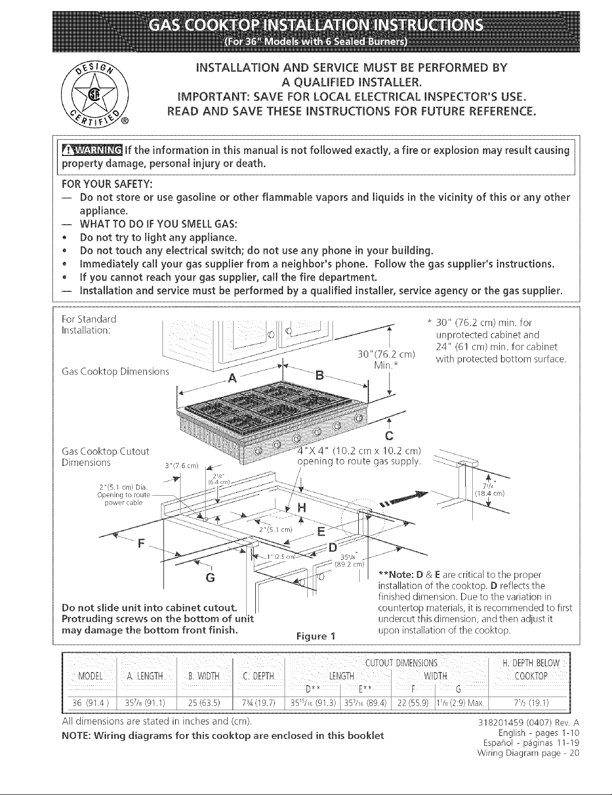
For Standard
Installation:
Gas Cooktop Dimensions
/A
GasCooktop Cutout
Dimensions
2"(5.1 cm) Dia.
Opening to route --
power cabFe
F
G
Do not slide unit into cabinet cutout,
Protruding screws on the bottom of ur it
may damage the bottom front finish.
X4" (!0.2 cm x 10.2 cm)
opening to route gas supply.
**Note: D & Eare critical to the proper
installation of the cooktop. D reflects the
finished dimension. Due to the variation in
countertop materials, it isrecommended to first
undercut this dimension, and then adjust it
Figure 1
upon installation of the cooktop.
* 30" (76.2 cm) rain. for
unprotected cabinet and
24" (61 cm) rain. for cabinet
with protected bottom surface.
71/4
(18.4 cm)
All dimensions are stated in inches and (cm).
NOTE: Wiring diagrams for this cooktop are enclosed in this booklet
318201459 (0407) Rev A
English - pages 1o10
Espar_ol - Diginas 11-19
Wiring Diagram page - 20
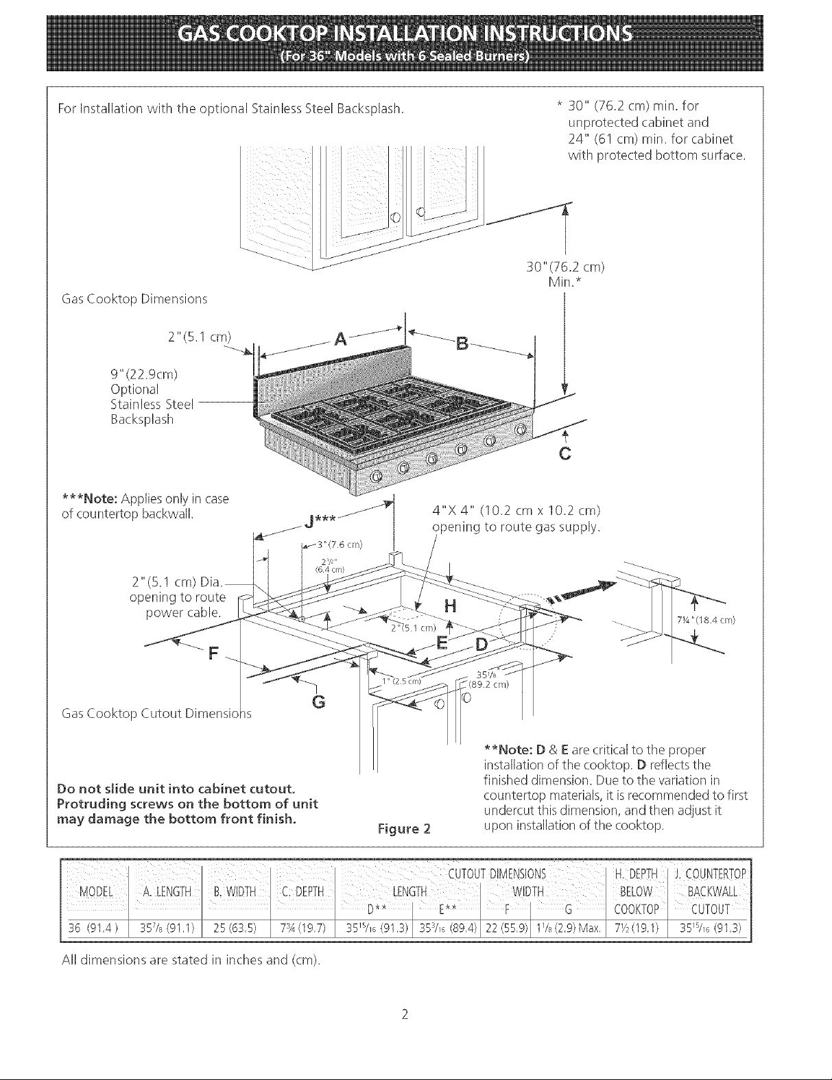
For Installation with the optional Stainless Steel Backsplash,
GasCooktop Dimensions
2" (5.1 cm)
9" (22.9cm)
Optional
Stainless Steel
Backsplash
* 30" (76.2 cm) rain, for
unprotected cabinet and
24" (6! cm) rain, for cabinet
with protected bottom surface.
***Note: Applies only in case
of countertop backwall.
4"X 4" (10,2 cmx 10,2 cm)
pening to route gas supply.
2" (5,1 cm)
opening to route
power cable.
H
7Y4"(18.4 cm)
351/_
cm/
GasCooktop Cutout Dimensicns
**Note: D & E are critical to the proper
installation of the cooktop. D reflectsthe
Do not sJide unit into cabinet cutout,
Protruding screws on the bottom of unit
may damage the bottom front finish.
Figure 2
finished dimension. Due to the variation in
countertop materials, it isrecommended to first
undercut this dimension, and then adjust it
upon installation of the cooktop.
MODiEI A:EENGTNI BwliTH I cDEPTH I WIDTH I BELOWI BA_KWA[E
l I CuTOuTDIMENSIONS H:DEPTH JiCOuNTERToP
36 (91,4) I 357/8(91'I) I 25(63,5) I 73A(19'7) 35W_6(91.3) I 3S3/_6(gg.4)I22(SS.g)IIVs(2.g)Max.I 7Y2(19,1) I 35m/_6(9I'3)
I I I D** I E** I FI G ICOOKTOPICUTOUT
All dimensions are stated in inches and (cm).
important Notes to the installer
1. Read all instructions contained in these installation
instructions before installing the cooktop.
2. Remove all packing material before connecting the
electrical supply to the cooktop.
3. Observe all governing codes and ordinances.
4. Be sure to leavethese instructions with the consumer.
5. Note: For operation at 2000 ft. elevations above see
level, appliance rating shall be reduced by 4 percent
for each additional I000 ft.
Important Note to the Consumer
Keep these instructions with your Use and Care Guide for
future reference.
Depth Adjustment FilmerKit #903051o9010
This cooktop isdesigned to replace existing unit. If the
depth of your countertop opening isbigger than 7_/4"(18.4
cm) and lessthan 8Y2" (21.6 cm) you can order a free filler
kit #903051-9010 by calling Sears Parts& Repair Center at
1-800-4-MY-HOME®.
Optional Item Available:
• A 9" (22.9cm) Stainless Steel Backsplash
Kit #903048-9010
This kit can be ordered for purchase through SearsParts
& Repair Center at 1-800-4-MY-HOME®.
IMPORTANT SAFETY
Be sure your cooktop is installed and grounded
properly by a qualified installer or service
technician.
• This cooktop must be electrically grounded in
accordance with tocat codes or, in their absence,
with the National Electrical Code ANSI/NFPA No.
70--latest edition in the United States, or in
Canada, with the Canadian Electrical Code, CSA
C22.1 Part 1.
• The burners can be tit manually during an
electricaJ power outage. To Hght a burner, hoJd a
tit match to the burner head, then slowly turn the
Surface Control knob to MTE. Use caution when
tighting burners manually.
• Do not store items of interest to children in
cabinets above the cooktop. Children could be
seriously burned climbing on the cooktop to reach
items.
• To eliminate the need to reach over the surface
burners, cabinet storage space above the burners
should be avoided.
• Adjust surface burner flame size so it does not
extend beyond the edge of the cooking utensit.
Excessive flame is hazardous.
• Never use your cooktop for warming or heating
the room. Prolonged use of the cooktop without
adequate ventilation can be hazardous.
• Do not store or use gasoline or other flammable
vapors and Jiquids near this or any other
appliance. Explosions or fires could result.
INSTRU S
Installation of this cooktop must conform with local (:odes
or, in the absence of local codes, with the National Fuel
Gas Code ANSI Z223.1/NFPA54--1atest edition in the
United States, or in Canada, with the Canadian Fuel Gas
Code, CAN/CGA B149 and CAN/CGA B149.2.
When installed in a manufactured (mobile) home
installation must conform with the Manufactured Home
Construction and Safety Standard, title 24 CFR,part
3280 [Formerly the Federal Standard for Mobile Home
Construction and Safety, title 24, HUD (part 280)] or,
when such standard is not applicable, the Standard for
Manufactured Home Installation, ANS!/NCSBCS A225.1
or with local codes where applicable.
This (ooktop has been design certified by CSA
International. As with any appliance using gas and
generating heat, there are certain safety precautions you
should follow. You will find them in the Use and Care
Guide, read it carefully.
The electrical power to the cooktop
must be shut off while gas line connections are
being made. Failure to do so coutd resutt in serious
injury or death.
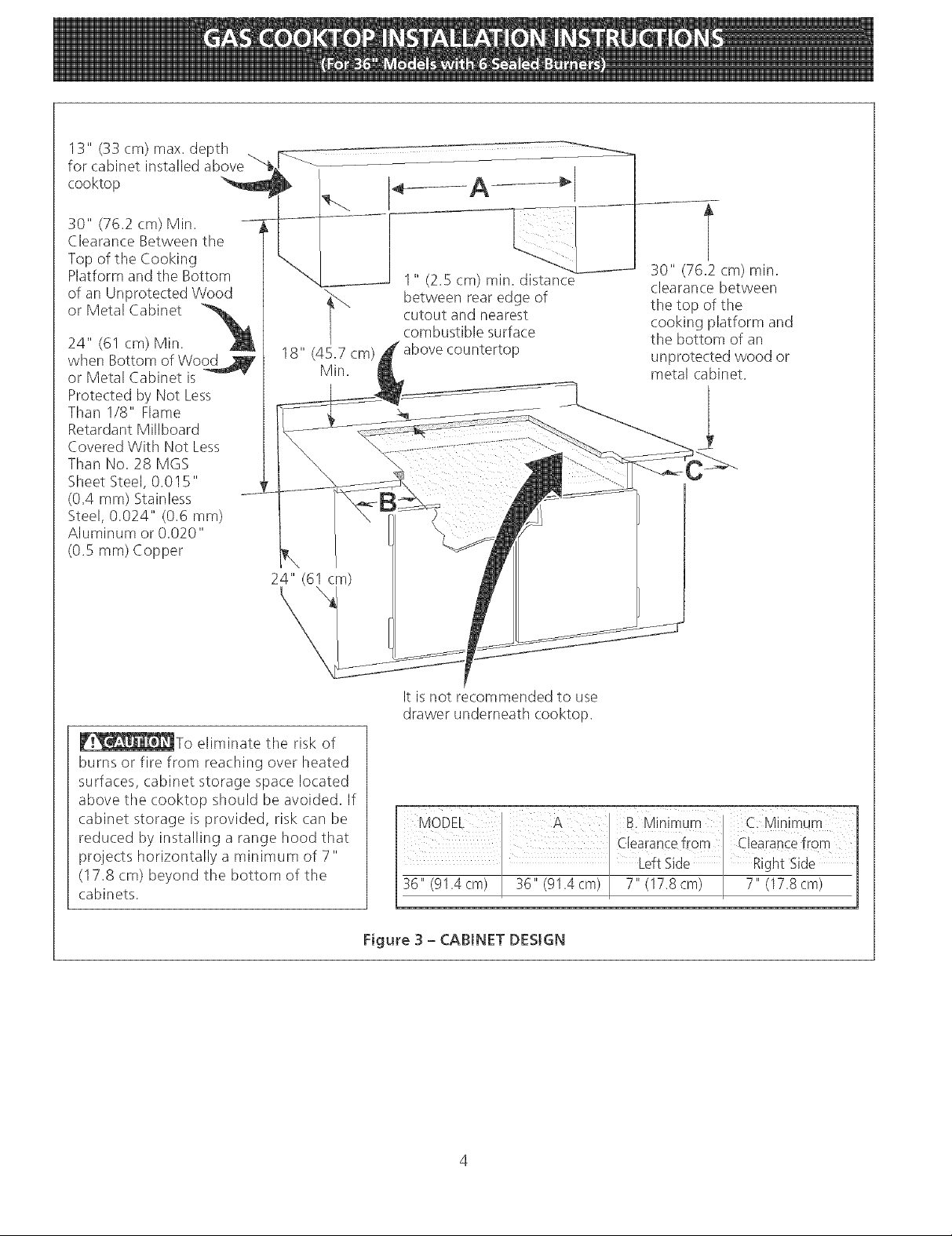
13" (33 cm) max. depth .
for cabinet installed above
cooktop
30" (76.2 cm) Min.
Clearance Between the
Top of the Cooking
Platform and the Bottom
of an Unprotected Wood
or Metal Cabinet
24" (61 cm)Min.
when Bottom of Wo_
or Metal Cabinet is -- "
Protected by Not Less
Than I/8" Flame
Retardant Millboard
Covered With Not Less
Than No. 28 MGS
Sheet Steel, 0.015"
(0.4 mm) Stainless
Steel, 0.024" (0.6 mm)
Aluminum or 0.020"
(0.5 ram) Copper
"_ between rear edge of
18" (45.7 cm) 'P
Min.
cutout and nearest
combustible surface
t
30" (76.2 cm) min.
clearance between
the top of the
cooking platform and
the bottom of an
unprotected wood or
metal cabinet.
_To eliminate tile risk of
burns or fire from reaching over heated
surfaces, cabinet storage space located
above tile cooktop should be avoided. If
cabinet storage is provided, risk can be
reduced by installing a range hood that
projects horizontally a minimum of 7"
(17.8 cm) beyond tile bottom of the
cabinets.
It isnot recommended to use
drawer underneath cooktop.
Figure 3 - CABINET DESIGN
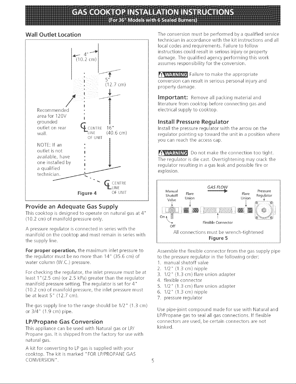
Wall Outlet Location
_ 4,,_
The conversion must be performed by a qualified service
technician in accordan(e with the kit instructions and all
local codes and requirements. Failure to follow
instructions could result in serious injury or property
damage. Tile qualified agency performing this work
assumes responsibility for the conversion.
(I0.2cm) .....
5"
0 (12.7 cm)
Recommended , |
area for 120V 'm |
grounded _ i
outlet on rear _CENTRE 16
wall. _LINE (40.6 cm)
OF UNIT
NOTE: If an
outlet is not 1
available, have
one installed by I
a qualified ,
technician.
"_ GCENTR E
Figure 4 OFUNIT
Provide an Adequate Gas Supply
This cooktop is designed to operate on natural gas at 4"
(10.2 cm) of manifold pressure only.
A pressure regulator is connected in series with the
manifold on the cooktop and must remain in series with
the supply line.
ii
LLINE
Failure to make the appropriate
conversion can result in serious personal injury and
property damage.
Important: Remove all packing material and
literature from cooktop before connecting gas and
electrical supply to cooktop.
Install Pressure Regulator
Install the pressure regulator with the arrow on the
regulator pointing up toward the unit in a position where
you can reach the access cap.
Do not make the connection too tight.
The regulator is die cast. Overtightening may crack the
regulator resulting in a gas leak and possible fire or
explosion.
Manual _
Shutoff FUare Flare
Valve
, /A" ...... .......
Union Union
GAS FLOW
OntN
_-_ F[exibme Connector
Off
All connections must be wrench4ightened
Figure 5
Pressu_-e
Reg_Bator
For proper operation, the maximum inlet pressure to
the regulator must be no more than 14" (35.6 cm) of
water column (W.C.) pressure.
For checking the regulator, tile inlet pressure must be at
least 1"(2.5 cm) (or 2.5 kPa) greater than the regulator
manifold pressure setting. The regulator isset for 4"
(10.2 cm) of manifold pressure, the inlet pressure must
be at least 5" (12.7 cm).
Tile gas supply line to the range should be 1/2" (1.3 cm)
or 3/4" (1.g cm) pipe.
LP/Propane Gas Conversion
This appliance can be used with Natural gas or LP/
Propane gas. It is shipped from the factory for use with
natural gas.
A kit for converting to LPgas is supplied with your
cooktop. The kit is marked "FOR LP/PROPANEGAS
CONVERSION".
Assemble the flexible connector from the gas supply pipe
to the pressure regulator in tile following order:
1. manual shutoff valve
2. 1/2" (1.3 cm) nipple
3. 1/2" (! .3 cm) flare union adapter
4. flexible connector
5. 1/2" (1.3 cm) flare union adapter
6. 1/2" (1.3 cm) nipple
7. pressure regulator
Use pipe-joint compound made for use with Natural and
LP/Propane gas to seal all gas connections. If flexible
connectors are used, be certain connectors are not
kinked.
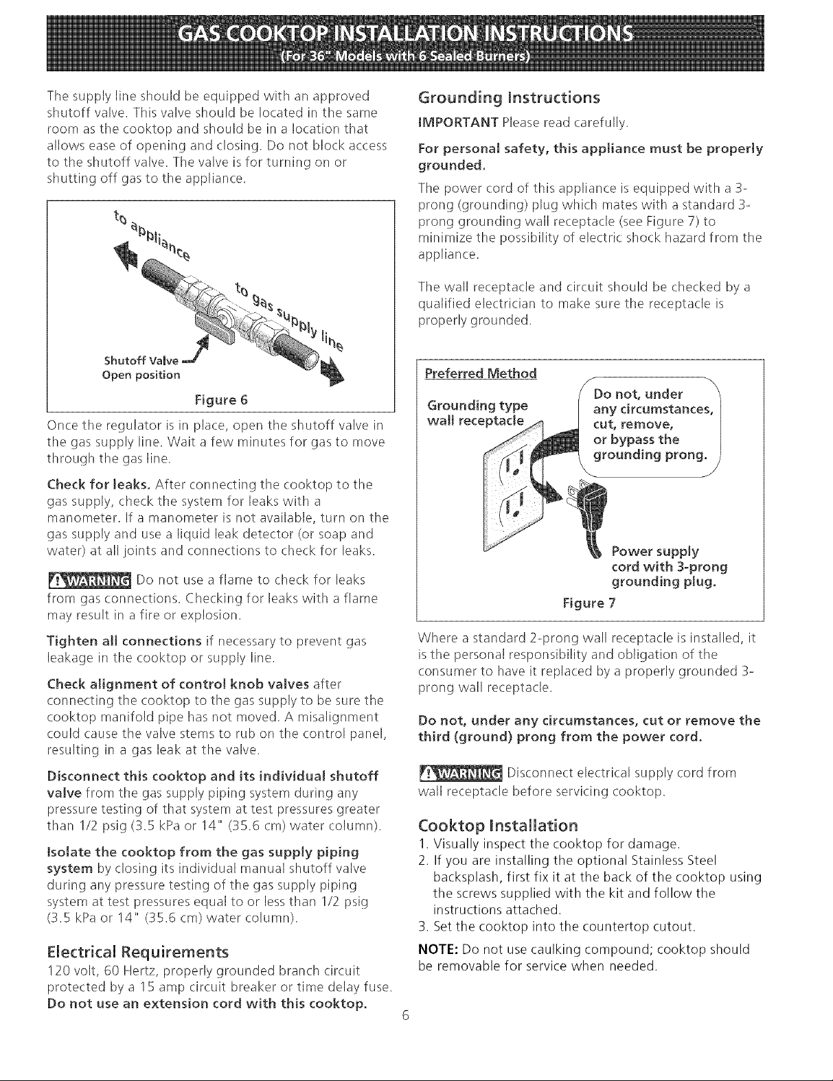
Thesupplylineshouldbeequippedwithanapproved
shutoffvalve.Thisvalveshouldbelocatedinthesame
roomasthecooktopandshouldbeina locationthat
allowseaseofopeningandclosing.Donotblockaccess
totheshutoffvalve.Tilevalveisforturningonor
shuttingoffgasto theappliance.
Grounding Instructions
IMPORTANT Please read carefully.
For personal safety, this appliance must be properly
grounded.
The power cord of this appliance is equipped with a 3-
prong (grounding) plug which mates with astandard 3-
prong grounding wall receptacle (see Figure 7) to
minimize the possibility of electric shock hazard from the
appliance.
The wall receptacle and circuit should be checked by a
qualified electrician to make sure the receptacle is
properly grounded.
Shutoff Valve
Open position
Figure 6
Once the regulator is in place, open the shutoff valve in
the gas supply line. Wait a few minutes for gas to move
through tile gas line.
Check for leaks. After connecting the cooktop to the
gas supply, check the system for leaks with a
manometer. If a manometer is not available, turn on the
gas supply and use a liquid leak detector (or soap and
water) at all joints and connections to check for leaks.
Do not use a flame to check for leaks
from gas connections. Checking for leaks with a flame
may result in afire or explosion.
Tighten all connections if necessary to prevent gas
leakage in the cooktop or supply line.
Check alignment of control knob valves after
connecting the cooktop to the gas supply to be sure the
cooktop manifold pipe has not moved. A misalignment
could cause the valve stems to rub on the control panel,
resulting in a gas leak at tile valve.
Disconnect this cooktop and its individual shutoff
valve from the gas supply piping system during any
pressure testing of that system at test pressures greater
than 1/2 psig (3.5 kPa or 14" (35.6 cm) water column).
tsotate the cooktop from the gas supply piping
system by (:losing its individual manual shutoff valve
during any pressure testing of the gas supply piping
system at test pressures equal to or less than 1/2 psig
(3.5 kPa or 14" (35.6 cm) water column).
Electrical Requirements
120 volt, 60 Hertz, properly grounded branch circuit
protected by a 15 amp circuit breaker or time delay fuse.
Do not use an extension cord with this cooktop.
Preferred Method
Grounding type
wall receptacle
/
f
(
cord with 3-prong
grounding plug,
Figure 7
Where a standard 2-prong wall receptacle is installed, it
is the personal responsibility and obligation of the
consumer to have it replaced by a properly grounded 3-
prong wall receptacle.
Do not, under any circumstances, cut or remove the
third (ground) prong from the power cord.
Disconnect electrical supply cord from
wall receptacle before servicing cooktop.
Cooktop Installation
1. Visually inspect the cooktop for damage.
2. If you are installing the optional Stainless Steel
backsplash, first fix it at the back of the cooktop using
the screws supplied with the kit and follow the
instructions attached.
3. Set the cooktop into the countertop cutout.
NOTE: Do not use caulking compound; cooktop should
be removable for service when needed.
 Loading...