

Kenmore 79030552803, 79030553803, 79030554803, 79030559803, 79030529802 Installation Guide
...
iNSTALLATiON AND SERVICE MUST BE PERFORMED BY
A QUALIRED iNSTALLER.
iMPORTANT: SAVE FOR LOCAL ELECTRICAL INSPECTOR'S USE.
READ AND SAVE THESE INSTRUCTIONS FOR FUTURE REFERENCE.
if the information in this manual is not followed exactly, a fire or explosion may result
causing property damage, personal injury or death.
FOR YOUR SAFETY:
Do not store or use gasoline or other flammable vapors and liquids in the vicinity of this or any other
appliance.
WHAT TO DO iF YOU SMELLGAS:
* Do nottry to light any appliance.
* Do nottouch any electrlcal switch; do not use any phone in your building.
* immediately call your gas supplier from a neighbor's phone. Follow the gas suppller's instructions.
* if you cannot reach your gas supplier, call the fire department.
installation and service must be performed by a qualified installer, service agency or the gas supplier.
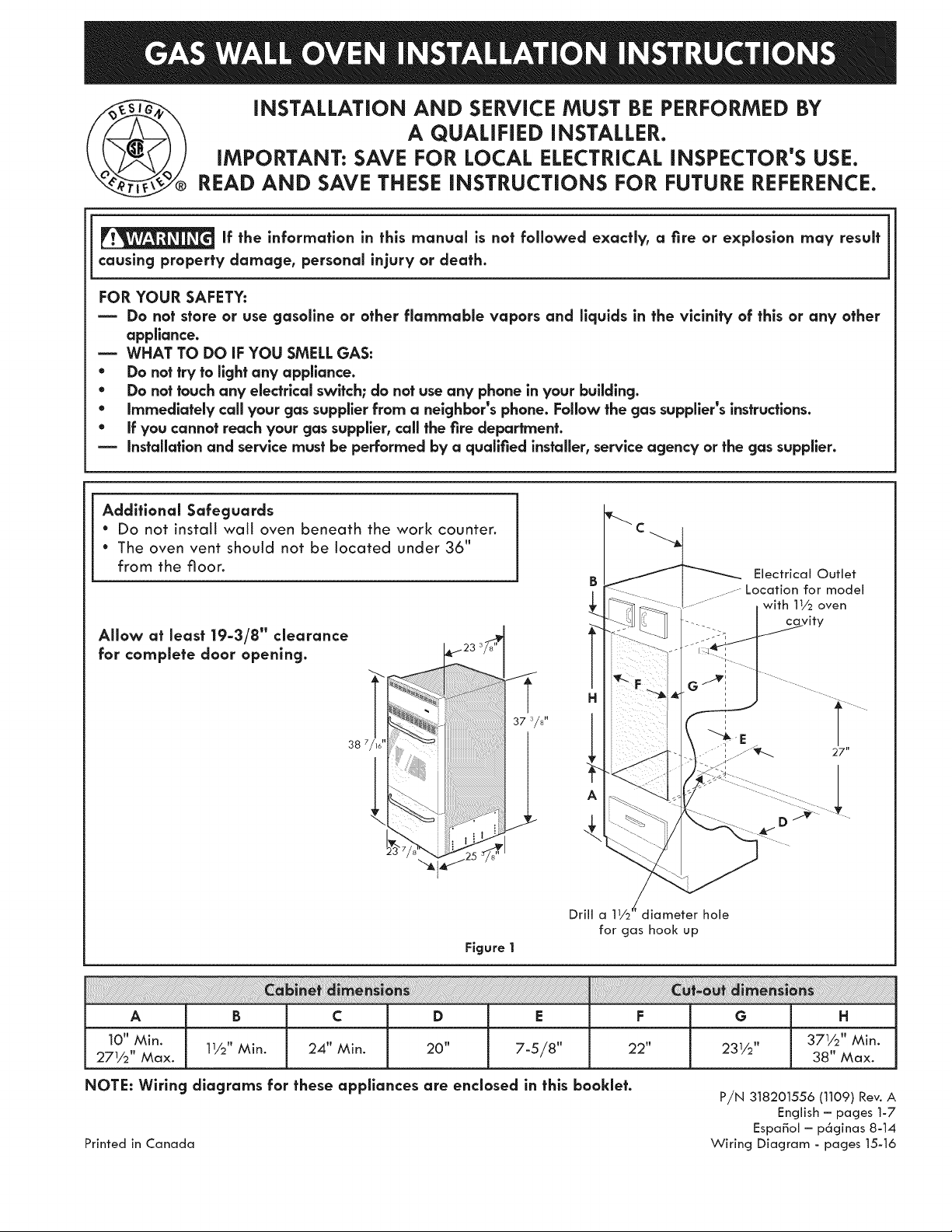
Additional Safeguards
• Do not install wait oven beneath the work counter.
• The oven vent shoutd not be located under 36"
from the floor.
Electrical Outlet
......Location for model
with 11/2 oven
Allow at least 19=3/8" clearance
for complete door opening.
38 /16
A
Drill a 11/2 diameter hole
for gas hook up
Figure 1
A B C D E F G H
10" Min. 24" 20" 22" 371/2'' Min.
271/2'' Max. 11/2'' Min. Min. 7-5/8" 231/2" 38" Max.
NOTE: Wiring diagrams for these appliances are enclosed in this booklet.
Printed in Canada
P,/N 318201556 (1109) Rev. A
English - pages 1-7
EspaBol - p6ginas 8-14
Wiring Diagram - pages 15-16
important Notes to the installer
I. Read all instructions contained in these installation
instructions before installing the appliance.
2. Remove all packing materiai and literature
from the oven and broiler compartments before
connecting gas and electric supply.
3. Observe all governing codes and ordinances.
4. Be sure to leave these instructions with the
consumer.
5. Note: For operation at 2000 ft. elevations above
see level, appliance rating shall be reduced by 4
percent for each additional 1000 ft.
important Nofe to the Consumer
Keep these instructions with your Use and Care
Guide for future reference.
Save these instructions for local inspectors.
iMPORTANT SAFETY
iNSTRUCTiONS
POWER FAILURE
Do not attempt to operate the oven in the event
of a power failure. If power failure should
occur during operation, turn the oven control
to the OFF position. Failure to turn the oven
control off will result in oven operation upon
resumption of power to the unit.
installation of these appliances must conform with
local codes or, in the absence of local codes, with
the National Fuel Gas Code ANSi Z223.1--1atest
edition.
These appliances have been design certified by
American Gas Association (A.G.A.). As with any
appliance using gas and generating heat, there are
certain safety precautions you should follow. You
will find them in the Use and Care Guide., read it
carefully.
• Be sure your wall oven is installed and
grounded properly by a qualified installer or
service technician.
• These wall ovens must be electrlcally grounded
in accordance with local codes or, in their
absence, with the National Electrical Code
ANSI/NFPA No. 70--latest edition. See
grounding instructions farther in this manual.
• The installation of appliances designed for
manufactured (mobile) home installatlon must
conform with Manufactured Home Construction
and Safety Standard Title 24CFR, Part 3280
[Formerly the Federal Standard for Mobile
Home Construction and Safety, Title 24, HUD,
(Part 280)] or when such standard is not
applicable the Standard for Manufactured Home
installation 1982 (Manufactured Home Sites,
Communities and Set=Ups), ANSi Z225.1/NFPA
501=A= latest edition, or with local codes.
Do not store items or food of interest
to children in the cabinets above the appllance.
Children could be seriously burned or injured if
they climb on the appliance to reach these items.
* Do not store or use gasoline or other flammable
vapors and liquids near this or any other
appllance. Explosions or fires could resutt.
* Be certain alt packing materials are removed
from the unit before operating, to prevent fire
or smoke damage should the packing material
ignite.
* Do not leave children alone in the kitchen
when the appliance is in use. They should not
be attowed to sit or stand on any part of the
appliance, as injury or burns coutd resutt. Keep
children from touching the oven door or glass
window when the appliance is operating, as the
door or window could get hot enough to cause
serious burns.
* Remove broiler tray and other utensils from oven
before using the self-clean cycle (if equipped).
* Do not use the oven as a store space. This creates
a potentially hazardous situation.
The appliance requires fresh air for proper burner
combustion. Do not obstruct the flow combustion
air at the oven vent or around the base or
beneath the lower front panel of the appliance.
Avoid touching the event openings or nearby
surfaces, as they may become hot.
* Remember, your oven is not designed to heat your
kitchen. Such abuse could result in fire and/or
damage to the unit and will void your warranty.
1. Carpentry
* Refer to figure 1 for the dimensions applicable
to your appliance, and the space necessary to
receive the oven. Corners must be square.
* Floor cabinet must be able to support 150 pounds
and must be flush with bottom of opening.
2. Connect Electricify Io Gas Wall Oven
For personal safety, these appliances must be
properly grounded.
This appliance is equipped with a
three-prong grounding plug for your protection
against shock hazard and must be plugged directly
into a properly grounded receptacle. Do not cut or
remove grounding prong from this plug.
The walt receptacle and circuit should be checked
by a qualified electrician to make sure the
receptacle is properly grounded.
Where a standard 2-prong walt receptacle is
installed, it is the personal responsibility and
obligation of the consumer to have it replaced by a
property grounded 3-prong wall receptacle.
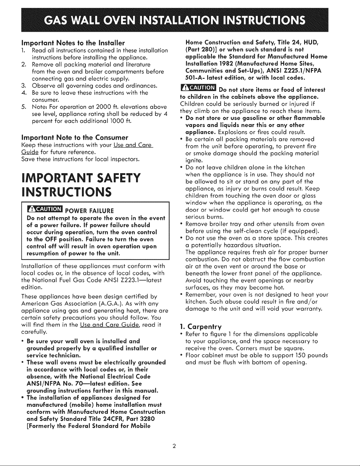
Preferred Method _o not,under anh
I circumstances, cut, I
remove, or bypass I
Grounding ¢-/4.._!1_ the grounding J
type watt _!_ pr°ng • //
receptacle
Figure 2
Do not, under any circumstances, cut or remove
the third (ground) prong from the power cord.
If an externat electrical source is used, the
appliance, when installed, must be electrically
grounded in accordance with local codes or in their
absence of local codes with the National Electric
Code ANSI/NFPA No. 70-1987 or latest edition.
Power supply cord with
_ 3-prong grounding plug
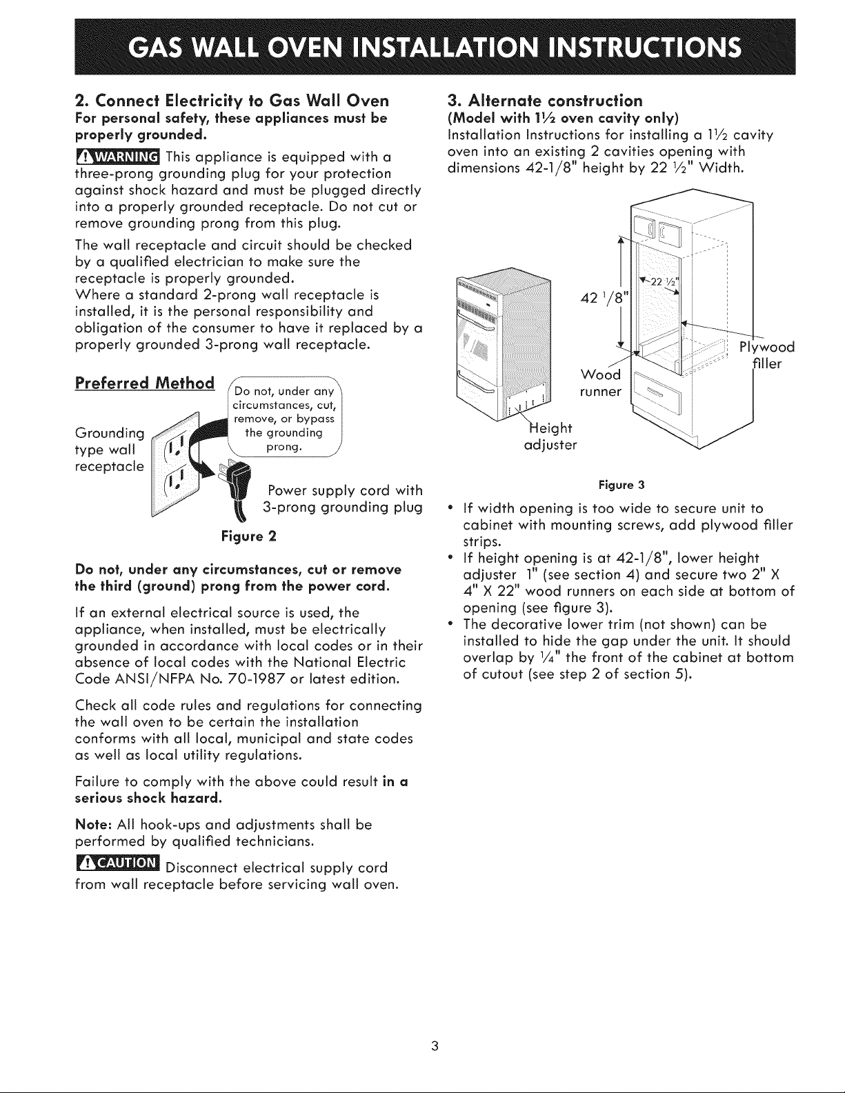
3. Alternate construction
(Model with 11.6oven cavity only)
Installation instructions for installing a 11/2 cavity
oven into an existing 2 cavities opening with
dimensions 42-1/8" height by 22 1/2" Width.
42
Wood
runner
eight
adjuster
Figure 3
* If width opening is too wide to secure unit to
cabinet with mounting screws, add plywood filler
strips.
" If height opening is at 42-1/8", lower height
adjuster 1" (see section 4) and secure two 2" X
4" X 22" wood runners on each side at bottom of
opening (see figure 3).
" The decorative lower trim (not shown) can be
installed to hide the gap under the unit. It should
overlap by 1/4" the front of the cabinet at bottom
of cutout (see step 2 of section 5).
Check all code rules and regulations for connecting
the walt oven to be certain the installation
conforms with all local, municipal and state codes
as well as local utility regulations.
Failure to comply with the above could result in a
serious shock hazard.
Note: All hook-ups and adjustments shall be
performed by qualified technicians.
Disconnect electrical supply cord
from walt receptacle before servicing walt oven.
3
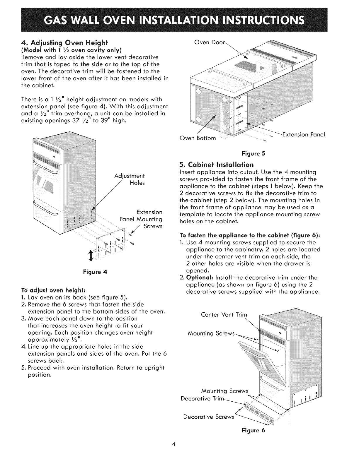
4. Adjusting Oven Height
(Model with 1 t½ oven cavity only)
Remove and lay aside the lower vent decorative
trim that is taped to the side or to the top of the
oven. The decorative trim will be fastened to the
lower front of the oven after it has been installed in
the cabinet.
There is a 1 1/2" height adjustment on models with
extension panel (see figure 4). With this adjustment
and a 1/2" trim overhang, a unit can be installed in
existing openings 37 1/2" to 39" high.
Oven Door
Adjustment
Holes
Extension
.............Panel Mounting
- .... " .... / Screws
Figure 4
To adjust oven height:
1. Lay oven on its back (see figure 5).
2. Remove the 6 screws that fasten the side
extension panel to the bottom sides of the oven.
3. Move each panel down to the position
that increases the oven height to fit your
opening. Each position changes oven height
approximately 1/2".
4. Line up the appropriate holes in the side
extension panels and sides of the oven. Put the 6
screws back.
5. Proceed with oven installation. Return to upright
position.
Oven Bottom
Figure 5
Extension Panel
5. Cabinet installation
Insert appliance into cutout. Use the 4 mounting
screws provided to fasten the front frame of the
appliance to the cabinet (steps 1 below). Keep the
2 decorative screws to fix the decorative trim to
the cabinet (step 2 below). The mounting holes in
the front frame of appliance may be used as a
template to locate the appliance mounting screw
holes on the cabinet.
To fasten the appilance to the cabinet (figure 6):
1. Use 4 mounting screws supplied to secure the
appliance to the cabinetry. 2 holes are located
under the center vent trim on each side, the
2 other holes are visible when the drawer is
opened.
2. Optionah Instatt the decorative trim under the
appliance (as shown on figure 6) using the 2
decorative screws supplied with the appliance.
Center Vent Trim
Mounting Screws
Decorative
Decorative
4
Mounting Screws
Figure 6
6° Provide an Adequate Gas Supply
Important: Read these instructions carefully before
connecting this unit to a gas supply.
The units covered in these instructions are designed
to operate on natural gas at 4" of manifold
pressure or on LP gas at 10" of manifold pressure.
A convertible pressure regulator is connected
in series with the manifold of the walt oven unit
and must remain in series with the supply line,
regardless of which type of gas is being used.
For proper operation, the maximum inlet pressure
to the regulator must not exceed 14" of water
column (W.C.) pressure.
To check the regulator, the inlet pressure must be
at least 1" (or 3.4 kPa) greater than the regulator
pressure setting. If the regulator is set for 4", the
inlet pressure must be at least 5". If the regulator is
set for 10", the inlet pressure must be at least 11".
A manual shut-off valve must be installed on the
gas supply line external to the unit and where it
can be easily reached for the purpose of turning
the gas to the unit on and off.
The gas supply line to the unit should be 1/2" (1.3
cm) or 3,,&"(1.9 cm) pipe.
To avoid pilot outage (if applicable) close all
openings in the cabinet cavity that encloses this
unit. All openings around gas service outlets must
be closed at the time of installation.
BEFORE CONNECTING THE UNIT
Remove all packing material and literature from
wait oven before connecting gas and electrical
supply to the appliance.
If applicable, remove broiler or storage drawer
by pulling drawer out to stops. Lift drawer front to
clear stops and putt out.
Check for leaks. After connecting gas, check
system for leaks with a manometer, if a manometer
is not available shut all pilots off (if present), turn
on the gas supply to the unit and use a liquid leak
detector at all joints and connections.
Tighten all connections if necessary to prevent gas
leakage in the wait oven or supply line.
IMPORTANT: A pipe joint sealant resistant to
the action of LP Gas must be used on all pipe
connections.
Do not use a flame to check for leaks
from gas connections. Checking for leaks with a
flame may result in a fire or explosion.
Disconnect the oven and its individual shutoff
valve from the gas supply piping system during
any pressure test greater than 1/2psig.
Isolate the wall oven from the gas supply piping
system by closing its individual manual shutoff
valve during any pressure testing of the gas supply
piping system at test pressures equal to or less than
1/2 psig.
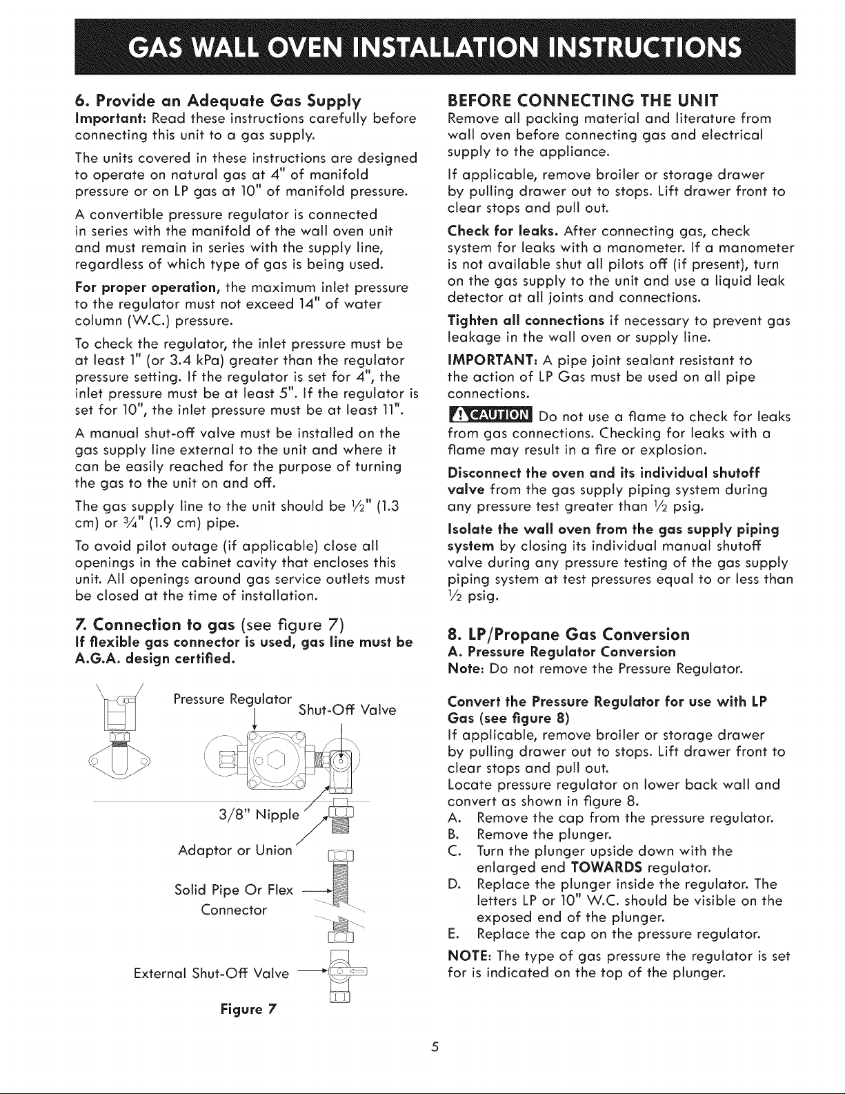
7. Connection to gas (see figure 7)
If flexible gas connector is used, gas llne must be
A.G.A. design certified.
Connector
External Shut-Off Valve __
Figure 7
8° LP/Propane Gas Conversion
A. Pressure Regulator Conversion
Note: Do not remove the Pressure Regulator.
Convert the Pressure Regulator for use with LP
Gas (see figure 8)
If applicable, remove broiler or storage drawer
by pulling drawer out to stops. Lift drawer front to
clear stops and putt out.
Locate pressure regulator on lower back walt and
convert as shown in figure 8.
A. Remove the cap from the pressure regulaton
B. Remove the ptungen
C. Turn the plunger upside down with the
enlarged end TOWARDS regulator.
D. Replace the plunger inside the regulator. The
letters LP or 10" W.C. should be visible on the
exposed end of the plunger.
E. Replace the cap on the pressure regulator.
NOTE: The type of gas pressure the regulator is set
for is indicated on the top of the plunger.
5
 Loading...