

Kenmore 75251 - 24, 500 BTU Room Air Conditioner, 580. 75251 Owner's Manual
Owner's Manual
Manual del
®
I
Model, Modelo 580. 75251
V
Distribut_ by Sears, Roebuck and Co., Hoffman Estates, IL 60179
www.sears.com
TABLE OF CONTENTS ........................2
Features ................................................. 10
WARRANTY ..............................................2
SAFETY ..................................................... 3
Important Safety Instructions ...................... 3
ELECTRICAL REQUIREMENTS .......4
INSTALLING THE POWER CORD ....4
INSTALLATION ........................................5
Installation Requirements ......................... 5
Installation ................................................ 6
How to Install ............................................ 6
Removal from Window ................................. 8
OPERATION .............................................9
How and Why ........................................... 9
Normal Sounds ........................................ 9
Capacity and Running Time ..................... 9
Using the Air Conditioner ....................... 10
Display ................................................... 11
Remote Control ...................................... 12
MAINTENANCE .....................................13
Air Filter Cleaning ................................... 13
Air Conditioner Cleaning ........................ 13
How to Remove the Front Grille .................. 13
How to Replace the Front Grille .................. 13
TROU B LES HOOTI NG .........................14
Before Calling for Service ...................... 14
ESPANOL ................................................15
MASTER PROTECTION
AGREEMENTS ......................................31
SERVICE NUMBERS ............ Back Cover
FULL ONE YEAR WARRANTY ON
ROOM AIR CONDITIONER
For one year from the date of purchase, when this
air conditioner is operated and maintained for
normal room cooling according to the instructions in
this owner's manual, Sears will repair this air
conditioner, free of charge, if defective in material or
workmanship.
FULL FIVE-YEAR WARRANTY ON
SEALED REFRIGERATION SYSTEM
For five years from the date of purchase, when this
air conditioner is operated and maintained for
normal room cooling according to the instructions in
this owner's manual, Sears will repair the sealed
refrigeration system (consisting of refrigerant,
connecting tubing, and compressor), free of charge,
if defective in material or workmanship.
WARRANTY SERVICE IS AVAILABLE BY
CONTACTING SEARS SERVICE AT
1-800-4-MY-HOME ®.
Warranty coverage applies only to air conditioners
used for non-commercial, private household
purposes.
This warranty applies only while this product is in
use in the United States.
This warranty gives you specific legal rights, and
you may also have other right which vary from state
to state.
Distributed by Sears, Roebuck and
Co., Hoffman Estates, IL 60179
-2-
IMPORTANT SAFETY INSTRUCTIONS
The safety instructions below will tell you how to use your room air conditioner to avoid harm to yourself or
damage to your ROOM AIR CONDITIONER.
FOR YOUR SAFETY
Do not store or use gasoline or other flammable
vapors and liquids in the vicinity of this or any other
appliance. Read product labels for flammability and
other warnings.
PREVENT ACCIDENTS
To reduce the risk of fire, electrical shock, or injury
to persons when using your air conditioner, follow
basic precautions, including the following:
• Be sure the electrical service is adequate for the
model you have chosen.
• If the air conditioner is to be installed in a window,
you will probably want to clean both sides of the
glass first. If the window is a triple-track type with a
screen panel included, you may want to remove
the screen completely before installation.
• Be sure the air conditioner has been securely and
correctly installed according to the separate
installation instructions provided with this manual.
Save this manual and installation instructions for
possible future use in removing or reinstalling this
unit.
• Use gloves when handling the air conditioner.
Be careful to avoid cuts from sharp metal fins on
front and rear coils.
ELECTRICAL INFORMATION
The complete electrical rating of your new room air
conditioner is stated on the serial plate. Refer to the
rating when checking the electrical requirements.
• Be sure the air conditioner is properly grounded.
To minimize shock and fire hazards, proper
grounding is important. The power cord is
equipped with a three-prong grounding plug for
protection against shock hazards.
• Your air conditioner must be plugged into in a
properly grounded wall receptacle. If the wall
receptacle you intend to use is not adequately
grounded or protected by a time delay fuse or
circuit breaker, have a qualified electrician install
the proper receptacle.
• Do not run air conditioner with a protective
covering. This could result in mechanical damage
within the air conditioner.
• Do not use an extension cord or an adapter
plug.
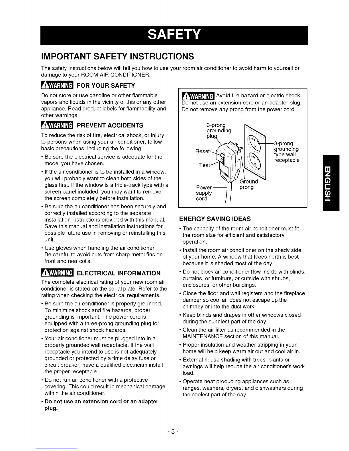
_ Avoid fire hazard or electric shock.
Do not use an extension cord or an adapter plug.
Do not remove any prong from the power cord.
3-prong
grounding
plug
--3-prong
grounding
Reset_
type wall
receptacle
"_ Ground
Power_ t prong
supply /f
cord II
ENERGY SAVING IDEAS
• The capacity of the room air conditioner must fit
the room size for efficient and satisfactory
operation.
• Install the room air conditioner on the shady side
of your home. A window that faces north is best
because it is shaded most of the day.
• Do not block air conditioner flow inside with blinds,
curtains, or furniture, or outside with shrubs,
enclosures, or other buildings.
• Close the floor and wall registers and the fireplace
damper so cool air does not escape up the
chimney or into the duct work.
• Keep blinds and drapes in other windows closed
during the sunniest part of the day.
• Clean the air filter as recommended in the
MAINTENANCE section of this manual.
• Proper insulation and weather stripping in your
home will help keep warm air out and cool air in.
• External house shading with trees, plants or
awnings will help reduce the air conditioner's work
load.
Operate heat producing appliances such as
ranges, washers, dryers, and dishwashers during
the coolest part of the day.
-3-
OBSERVEALL LOCAL CODES AND ORDINANCES,
DO NOT_UNDER ANY CIRCUMSTANCE& REMOVE
THE POWER SUPPLY CORD GROUND PRONG.
ELECTRICAL GROUND iS REQUIRED ON THIS
APPLIANCE.
For230/208 volt 60 Hz, AC only, 15A fused and
properly grounded dectrica] supply is required. A time
delay fuse or time delay circuit breaker is
recommended Use adedicated circuit, sewing only
this appliance_
DO NOT USE AN E_ENSION CORD.
RECOMMENDED GROUNDING M_HOD
Foryourpersona]safety,thisapCance must_ grounded
This app]ian_ hasapowersupply cordwith a 3-prong
groundingplug.To minimizepossibleshock hazard,the
®rd mustbe pluggedintoa matinggroundingtype wall
receptade andgroundedinacoord_ce withthe National
ElectricalCode (ANS[CNFPA70}latesteditionandall local
codes and ordinals. If a matingwallreceptade is not
available, _isthe personalres_nsibility and obiigalionof
the customerto havea properlygrounded3-prongwali
rece)tade instail_ byaqualifiedd_dciaq.
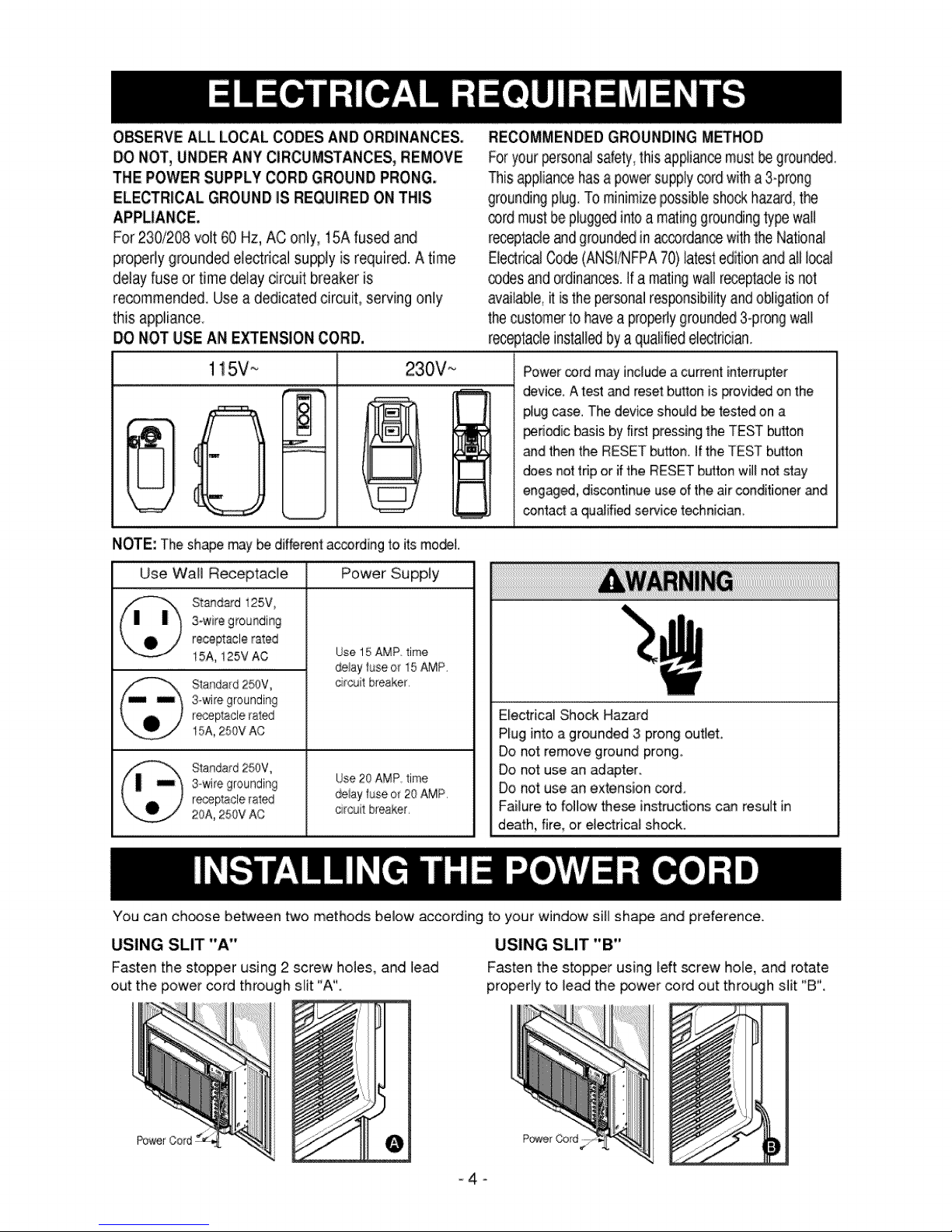
115V_ 230V_
i,
NOTE: The shape may be different accordhg to its mo_].
Use Wall Receptacle Power Supply
St_ds_d 125V,
3-wire grounding
receptacle rated
15A, 125V AC Use 15 AMP time
delay fuse or 15 AMP,
Standard 250V, citcuil b[eaker,
3-wire grounding
r_placle ral_]
15A, 250V AC
Standard 250V,
3-wire grounding Use20 AMP time
r÷_placle raled deiay fuse or 20 AMP,
20A, 250V AC c _cuit breaker,
Power _rd may includea current interrupter
device. A test _d reset button is provided on the
#ug case. The device shodd be tested on a
periodicbasis by first pressingthe TEST button
_d thenthe RESETbutton.Ifthe TESTbu_ton
doesnot trip or ifthe RESETbuttonwill notstay
engaged, discontinueuseofthe airconditionerand
contacta qualified servicet_hn[cian
Electrical Shock Hazard
Plug into a grounded 3 prong outbt.
Do not remove ground prong
Do not use an adapter,
Do not use an extension cor&
Failure to follow the_ instructions c_ result in
death, fire, or electrical sh_k.
You can choose between two methods bdow according to your window sill shape and preference.
USING SLIT "A"
Fasten the stopper using 2 screw holes, and lead
out the power _rd through siit "A'_
_f
USING SLIT "B"
Fasten the stopper using left _rew hole, and rotate
properly to lead the _wer cord out through silt "B".
-4-
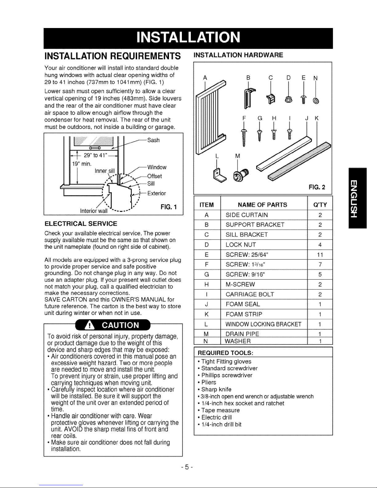
INSTALLATION REQUIREMENTS
Your air conditioner will install into standard double
hung windows with actual clear opening widths of
29 to 41 inches (737mm to 1041mm) (FIG. 1)
Lower sash must open sufficiently to albw a clear
vertical opening of 19 inches (483mm). Side louvers
and the rear of the air conditioner must have clear
air space to allow enough airflow through the
_ndenser for heat removal. The rear of the unit
must be outdoors, not inside a buiiding or garage.
19"rain.
Inner
Exterior
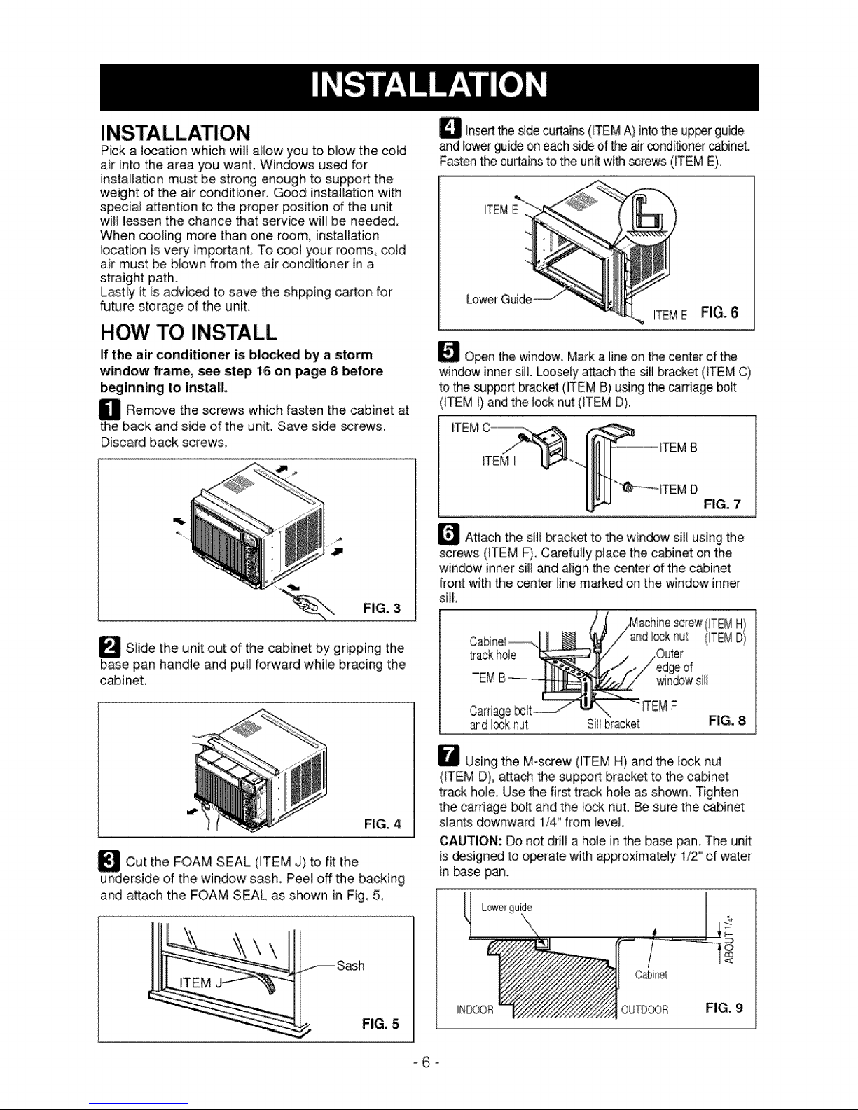
INSTALLATION HARDWARE
A
B C D E N
F G H I J K
FIG. 2
Interiorwall
FIG, 1
ELECTRICAL SERVICE
Check your available electrical service. The power
supply available must be the same as that shown on
the unit n_eplate (found on right: side of cabinet).
AH mode_s are equipped with a 3-prong service plug
to provide proper service and safe positive
grounding_ Do not change plug in any way, Do not
use an adapter plug. If your present wall outlet does
not match your plug, call a qualified electrician to
make the necessary corrections.
SAVE CARTON and this OWNER'S MANUAL for
future reference. The carton is the best way to store
unit during winter or when not in use.
To avoid risk of personal injury, property damage,
or product damage due to the weight of this
device and sharp edges that may be exposed:
• Air _nditioners covered in this manual pose an
excessive weight hazard. Two or more people
are ne_ed to move and install the unit.
To prevent injury or strain, use proper li_ing and
carrying techniques when moving unit.
• Carefully inspect location where air _nditioner
will be installS. Be sure it will support the
weight of the unit over an extended peri_ of
time.
• Handle air _nditioner with care. Wear
protective gloves whenever lifting or car_ing the
unit. AVOID the sharp metal fins of front and
rear coils.
• Make sure air conditioner does not fali during
installation.
ITEM NAME OF PARTS Q'TY
A SIDE CURTAIN 2
B SUPPORT BRACKET 2
C SILL BRACKET 2
D LOCK NUT 4
E SCREW: 25/64" 11
F SCREW: 13/16" 7
G SCREW: 9/16" 5
H M-SCREW 2
I CARRIAGE BOLT 2
J FOAM SEAL 1
K FOAM STRIP 1
L WINDOWLOCKINGBRACKET 1
M DRAIN PiPE 1
N WASHER 1
REQUIRED TOOLS:
•Tight Fi_ing gloves
• Standard screwdriver
• Phillips screwdriver
• Pliers
• Sharp knife
°3/8-incho_n end wrenchor adjustablewrench
• 1/4-inch hex socket and ratchet
•Tape measure
° Electric drill
° 1/4-inch drill bit
-5-
Pick a location which will allow you to blow the cold
air into the area you want. Windows used for
installation must be strong enough to support:the
weight of the air conditioner. Good installation with
special attention to the proper position of the unit
will lessen the chance that service will be needed,
When cooling more than one room, installation
location is very important. To cool your rooms, cold
air must be blown from the air conditioner in a
straight path.
L_tly it is adviced to save the shpping carton for
future storage of the unit.
HOW TO INSTALL
If the air conditioner is bilked by a storm
window frame, see step 16 on page 8 before
b_inning to install.
_ Rernove the which fasten the cabinet
the back and side of the unit. Save side screws.
Discard back screws,
_ Slide the unit out of the cabinet by gripping the
base pan handle and pull forward while bracing the
cabinet.
screws at
FIG. 3
D Insertthe sidecurtains(_TEMA) intothe upperguide
and bwer gui@ on each si@ of the airconditionerca_net.
Fastenthe curtainsto the unRwith_rews (ITEME).
ITEME FIG. 6
_O_n the window. Marka line on thecenter of the
windowinnersi& Looselyattach the sill bracket (iTEM C)
to the support bracket(ITEMB) using thecarriage bolt
(iTEM i) and the Iocknut (iTEM D).
ITEM
ITEM I
_ Attach the sill bracket to the windowsill using the
screws (ITEM F). Carefully place the cabinet on the
window inner sill and alignthe center ofthe cabinet
front with the center line marked on the window inner
sill.
jMachine screw<!TEMH)
d [l_k nut {ITEMD)
ITEMF
andlocknut
\
Silibracket
FIG. 8
Cut the FOAM SEAL (ITEM J) to fit the
underside of the window sash. Peel off the backing
and attach the FOAM SEAL as shown in Fig, 5,
Sash
FIG. 4
FIG. 5
W Usingthe M-screw (ITEM H) and the I_k nut
(iTEM D}, atta@ the sup_rt bracket to the cabinet:
track hole, Use the first track hole as shown. Tighten
the carriage bolt and the Iod_nut. _ surethe cabinet
slants downward 1/4"from level,
CAUTION: Do not drill a hole in the base pan. The unit
is designed to operate with approximately 1/2" of water
in base pan.
Cabinet
OUTOOOR
-6-
FIG. 9
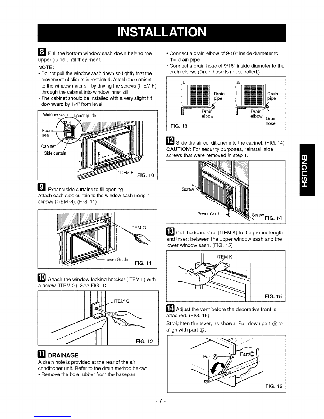
_PuH the bottom window sash down behind the
upper guide until they meet,
NOTE:
• Do not pull the window sash down so tightly that the
movement of sliders is restricted, Attach the cabinet
to the window inner sill by drMng the screws 0TEM F)
through the cabinet into window innersill.
• The c_inet should be installed with a very slight ti_t
downward by 1/4" from ]eve],
• _nnect adrain elbow of 9/16" inside diameter to
the drain pipe,
• _nnect a drain hose of 9/16" inside diameter to the
drain elbow. (Drain hose is not supplied.)
Drain
pipe
Windowsash
_TEMF FIG, 10
_ Expand side curtains to fill opening.
Attach each side curt:_n to the window sash using 4
screws (_TEM G) (F_G, 1i)
ITEM G
e_bow eMbow
FIG. 13
Drain
hose
_ Slide the air conditioner intothe cabinet. (FIG. 14)
CAUTION: For security purposes, reinstall side
screws that were removed in step I.
_Cut the,foam strip (_TEMK) to the proper _ength
and inse_ between the upper window sash and the
lower window sash..(FIG. 15)
_] Attach the window locking bracket (ITEM L) with
a screw (ITEM G). See FIG. 12.
a] DRAINAGE
A drain hole is provide, at the rear of the air
conditbner unit. Refer to the drain method below::
• Remove the hole wbber from the basepan.
ITEM G
FiG. 15
_ Adjust the vent before the decorative front is
attached, (FIG, 16)
Straighten the lever, as shown. Pull down part @to
align with part C_
FIG. 12
!'%ili
F_G, 16
-7=
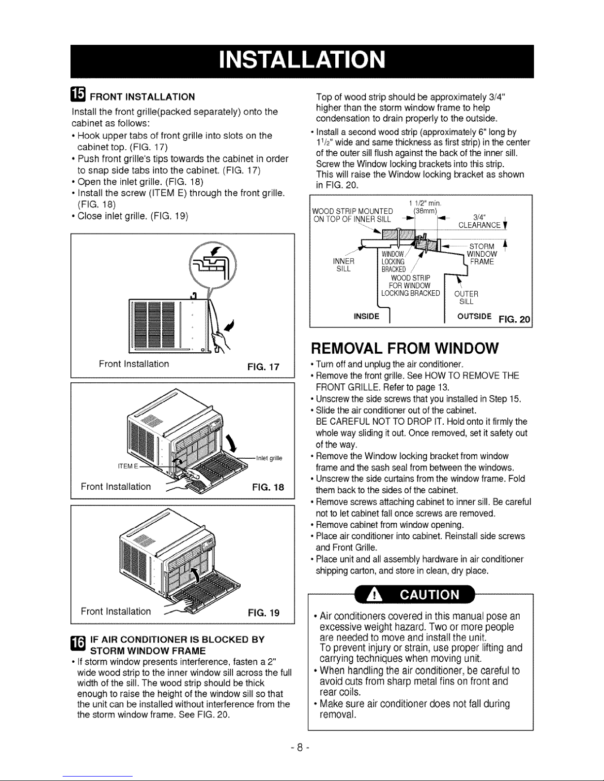
_ FRONT INSTALLATION
Install the front grille(packed separately) onto the
cabinet as foNows:
• Hook upper tabs of front gritle into slots on the
cabinet top. (FIG. 17)
• Push front griIWs tips towards the cabinet in order
to snap side tabs into the cabinet, (FIG, 17)
• Open the inlet grille. (FIG. 18)
• Install the screw (_TEM E) through the front grille.
(FIG. 18)
• Close inlet grille, (FIG, t9)
Top d wood strip should be approximately 3/4"
higher than the storm window frame to help
condensation to drain properly to the outside,
• _nstal_a _nd w_d strip(approximately6"long by
11/2"wide and samethickr_ss asfirst strip) in thecenter
ofthe outersill flush a_inst: the back ofthe inner sill,
Screwthe Window I_king bracketsintothis strip.
This will raisethe,Window locking bracket as shown
in FIG 20,
WOODSTRIP MOUNTED
ON TOP OF INNER SILl,,
3/4
CLEARANCE
Front Installation
_EM E
Front Installation
FiG. 17
FIG. 18
WINDOW
FRAME
SiLL
SILL
LOCKIt@
BPACKEO,'
WOODSTRIP
FORWINDOW
LOCK!NGBRACKED
OUTSlOE FIG, 20
REMOVAL FROM WINDOW
•Turn off and un#ug the air conditJonero
• Removethe front grille. See HOW TO REMOVETHE
FRONTGRILLE.Referto _ge 13.
• Undrew the side screwsthat you installedin Step 15,
• Slidetie air condiflo_r outof the cabinet.
BE CAREFULNOT TODROP IT. Holdonto it firmlythe
who_ewaysliding itold, Onceremoved,set it safetyout
of the way,
• Removethe Window locking bracketfromwindow
frameand the sashsea! from betweenthe windows,
° Unscrewthe sidecurtains fromthe windowframe, Fold
them backto the sidesof thecabinet.
• Removescrews attachingcabinetto inner sill. BecareDl
notto let _bJnet failon_ screwsare removed,
• Removecabinet from windowopening.
• Placeair conditionerinto _bJnet. Reinstallside screws
and Front Grii_e,
° Place unitand all assembly h_dware inair conditioner
shippingcarton, and storein clean,dry #ace.
Front Installation FIG. 19
IF AIR CONDITIONER IS BLOCKED BY
STORM WINDOW FRAME
• If storm window presents interference, fasten a 2"
wide wood strip to the inner window s]l! across the full
width of the sill. The wood strip should be thick
enough to raise the height of the window sill so that
the unit can be installed without interference from the
the storm window frame. See FIG. 20.
• Air _nditioners covered in this manual pose an
excessive weight hazard. Two or more people
are ne_ed to move and install the unit.
To prevent injury or strain, use proper lifting and
carrying techniques when moving unit.
° When handling the air conditioner, be careful to
avoid cuts from sharp metal fins on front and
rear coils.
• Make sure air conditioner does not fall during
removal.
-8-
HOW AND WHY
Your room air conditioner provides the following
functions to make hot weather iiv[ng more
comfo_able:
• Coo_sand circulates room air
* Lowers humidity by removing excess moisture.
, Filters out summertime dust, diR. and some
airborne impurities.
The air conditioner performs these functions by
drawing room air through a filter which traps dust
and dirt particles. The air then passes over a
cooling coil which refrigerates the air and removes
excess moisture. The same air is then returned to
the room- coo_er, drier, and cleaner. Moisture
removed from the room air is carried to the outside
and evaporated.
'(our air conditioner is designed to be easy to
operate and to provide pienty of cooling power.
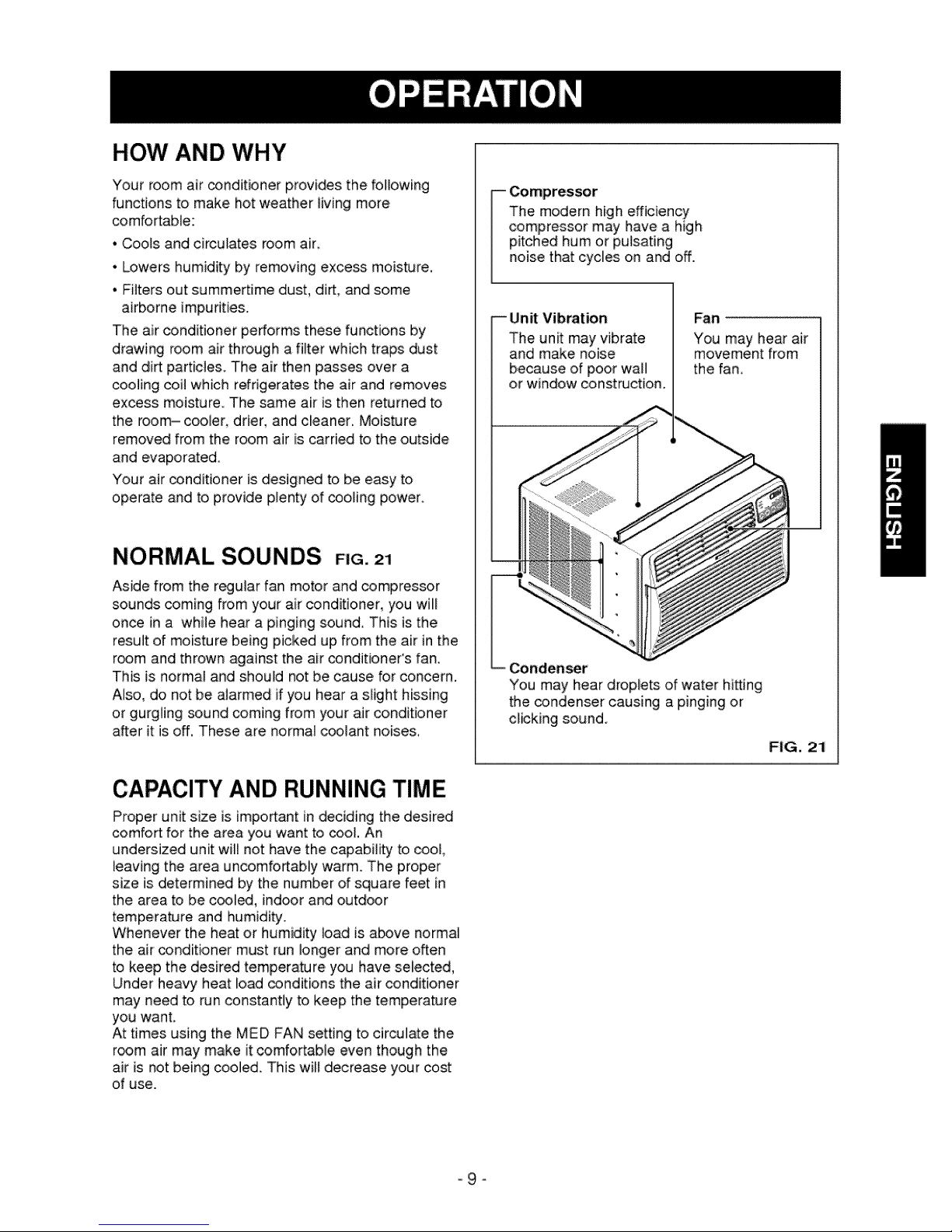
NORMAL SOUNDS F G.21
Aside from the r_ular fan motor and compressor
sounds coming from your air conditioner, you will
once in a while hear a pinging sound This is the
result of moisture being picked up from the air in the
room and thrown against the air conditioner's fan.
This is norma! and should not be cause for concern.
Also, do not:be alarmed if you hear a slight hissing
or gurgling sound coming from your air conditioner
after it is off. These are normal coolant noises,
The modern high efficiency
compressor may have a high
pitched hum or pulsating
noise that cycles on and off.
Unit Vibration
The unit may vibrate
and make noise
because of poor wall
or window const_ction.
_en_r
You may hear droplets of water hitting
the condenser causing a pingingor
clicking sound.
Fan
You may hear air
movement from
the fan.
FIG. 21
CAPACITY AND RUNNING TIME
Proper unit size is impo_ant in deciding the desired
comfort for the area you want to cool. An
undersized unit will not have the capability to cool,
_eavingthe area uncomfortably warm. The proper
size is determined by the number of square feet in
the area to be _l_, indoor and outdoor
temperature and humidity.
Whenever the heat or humidity load is a_ve normal
the air _nditioner must run longer and more often
to keep the desired temperature you have selected
Under heavy heat load conditions the air conditioner
may need to run constantly to keep the temperature
you want,
At times using the MED FAN setting to circulate the
r_m air may make it comfortable even though Lhe
air is not being cooled. This will decre_e your cost
of use.
-9-
1 15 6 5 4 316 2714
_ILT#
tltl
USING THE AIR CONDITIONER
To reduce the risk of fire, electric
shock, or injury to persons, re_ the important
SAFETY instructions section before operating this
appliance
To begin operating the air conditioner after
installation, follow these steps:
1. Plug in the air conditioner. (To prevent electrical
hazards, do not use an extension cord or an
adapter plug.)
2. Set the exhaust vent to the CLOSE position,
3. Set the TEMP Control to the coolest setting.
4. Set the MODE control at the highest COOL level
5, A_ust the louvers for comfortable air flow.
6, Once the room has cooled, adjust the TEMP end
Mode Contro_to the setting you find most
comfortable.
NOTE : if the air conditioner is turned off, wait 3
minutes before restarting. This allows pressure
inside the compres_r to equalize. Failure to wait 3
minutes before restarting may cause inefficient
operation,
ifyou move the TEMP Contro_ to a warmer, then
immediately back to a cooler setting, the unit will
shut off. Wait 3 minutes before restarting.
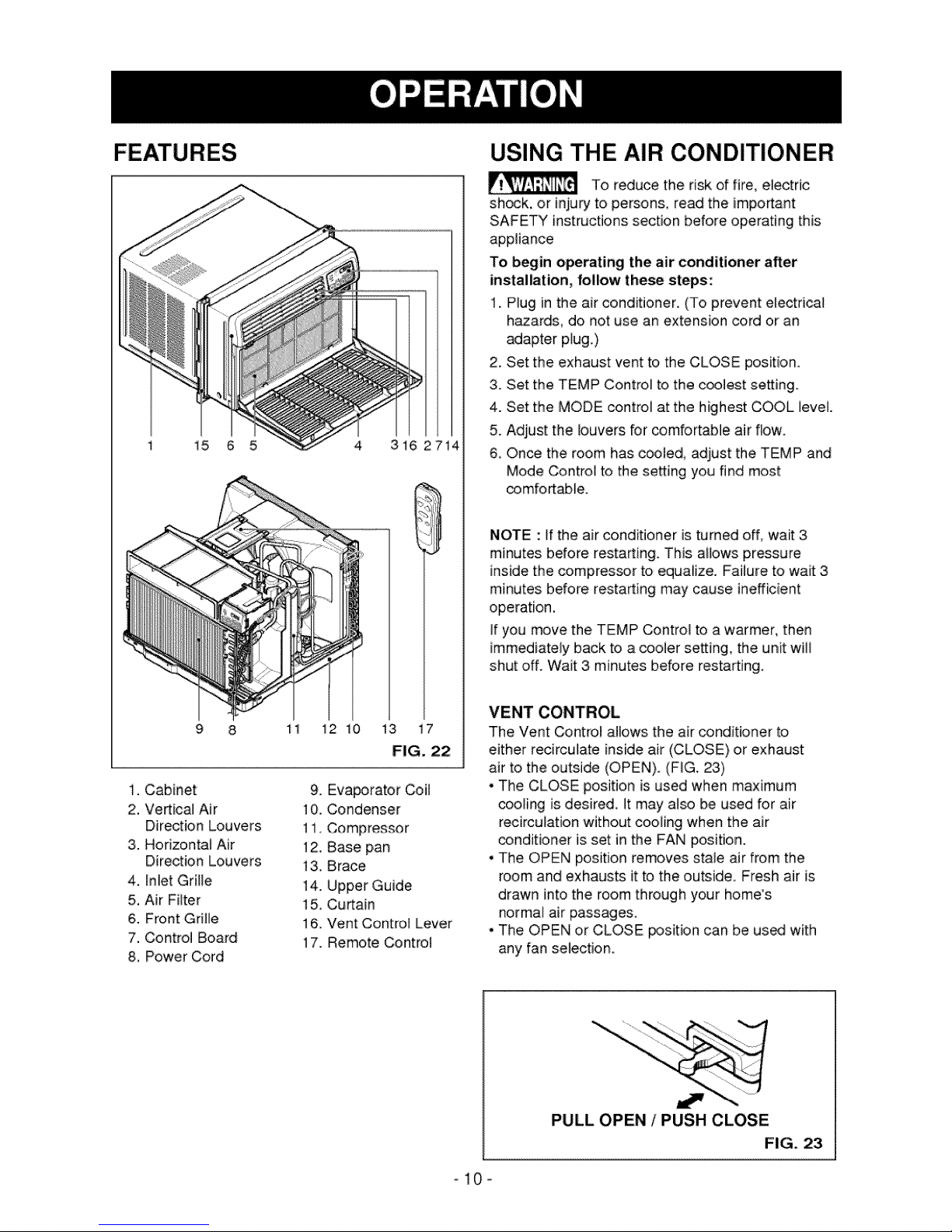
1. Cabinet
2. Vertical Air
Direction Louvers
3. Horizontal Air
Direction Louvers
4. In_etGrille
5. Air Filter
6. Front Grille
7. Control Board
8. Power Cord
11 i2 10 13 i7
FIG. 22
9. Evaporator Coil
10. Condenser
11, Compressor
12. Base pan
t 3.8race
14. Upper Guide
15, Curtain
16. Vent Control Lever
17. Remote Control
VENT CONTROL
The Vent Control allows the air conditioner to
either recirculate inside air (CLOSE) or exhaust
air to the outside (OPEN). (FIG. 23)
• The CLOSE position is used when maximum
cooling is desired Itmay also be used for air
recirculation without cooling when the air
conditioner is set in the FAN position.
• The OPEN position removes stale air from the
room and exhausts it to the outside. Fresh air is
drawn into the room through your home's
normal air passages
• The OPEN or CLOSE _sition can be used with
any fan selection.
PULL OPEN ! PUSH CLOSE
FiG. 23
-10-
 Loading...