

Kenmore 74182 User Manual
®
Coin- Operated
Commercial Dryer
Installation Instructions and
Use and Care Guide
Models: 64182, 74182
P/N 134313400D (0712) Sears, Roebuck and Co., Hoffman Estates, IL 60179 U.S.A. www.sears.com
Contents
Product Record
SUBJECT PAGE
Pre-Installation Requirements.................................2
Electrical Requirements..........................................3
Exhaust System Requirements............................3-4
Gas Supply Requirements.......................................4
Rough-In Dimensions..............................................5
Unpacking................................................................5
Reversing Door Swing.............................................5
For Sears warranty information or to contact a Sears Service
Center, call 1-800-4-my-HOME (1-800-469-4663)
If you need SERVICE or PARTS for your Kenmore
coin-operated washer: be ready to give the model
number, serial number and date of purchase. Record
below.
Location of Your Dryer.............................................6
Electrical Installation...............................................7
Model number__________________________________
Grounding Requirements........................................7
Electrical Connections—3-wire..............................8
Serial number___________________________________
Electrical Connections—4-wire..............................8
Installation................................................................9
Purchase date___________________________________
Lint Blade Retaining Pin Location...........................9
Meter case instructions......................................9-12
Replacement Parts.................................................12
Parts lists.........................................................13-14
Warranty...............................................................15
Record Coin Box
Key Number__________________________
Key number is on key and/or coin box.
Back Cover...........................................................16
DRYER SAFETY
Before beginning installation, carefully read these instructions. This will simplify the installation and ensure the dryer
is installed correctly and safely. Leave these instructions near the Dryer after installation for future reference.
NOTE: The electrical service to the Dryer must conform with local codes and ordinances and the latest edition of the
National Electrical Code, ANSI/NFPA 70.
NOTE: The gas service to the Dryer must conform with local codes and ordinances and the latest edition of the
National Fuel Gas Code ANSI Z223.1.
Your safety and the safety of others is very important. We have provided many important safety messages in the Installation
Instructions / Use & Care Guide and on your appliance. Always read and obey all safety messages.
This is the safety alert symbol. This symbol alerts you to hazards that can kill or hurt you or others. All safety messages will
be preceded by the safety alert symbol and the word "DANGER" or "WARNING". These words mean:
DANGER
All safety messages will identify the hazard, tell you how to reduce the chance of injury, and tell you what can happen if the
instructions are not followed.
property damage, personal injury or loss of life.
- Do not store or use gasoline or other flammable vapors and liquid in the vicinity of this or any other appliance.
- WHAT TO DO IF YOU SMELL GAS
· Do not try to light any appliance.
· Do not touch any electrical switch; do not use any phone in your building.
· Clear the room, building or area of all occupants.
· Immediately call your gas supplier from a neighbor’s phone. Follow the gas supplier's instructions.
· If you cannot reach your gas supplier, call the fire department.
Installations must be performed by a qualified or licensed contractor, plumber, or gasfitter qualified or licensed by the state,
province, or region where this appliance is being installed.
You can be killed or seriously injured if you don't immediately follow instructions.
can be killed or seriously injured if you don't follow instructions.
You
For your safety the information in this manual must be followed to minimize the risk of fire or explosion or to prevent
PRE-INSTALLATION REQUIREMENTS
Tools and Materials Required for Installation:
1. Phillips head screwdriver.
2. Channel-lock adjustable pliers.
3. Carpenter's level.
4. Flat or straight blade screwdriver.
5. Duct tape.
6. Rigid or flexible metal 4 inch (10.2 cm) duct.
7. Vent hood.
8. Pipe thread sealer (Gas).
9. Plastic knife.
2
ELECTRICAL REQUIREMENTS
ELECTRIC Dryer
CIRCUIT - Individual 30 amp. branch circuit fused with 30 amp.
time delay fuses or circuit breakers.
Use separately fused circuits for washers and dryers, and DO
NOT operate a washer and a dryer on the same circuit.
POWER SUPPLY - 3 wire, 240 volt, single phase, 60 Hz,
Alternating Current.
POWER SUPPLY CORD KIT - The dryer MUST employ a 3-
conductor power supply cord NEMA 10-30 type SRDT rated at
240 volt AC minimum, 30 amp., with 3 open end spade lug
connectors with upturned ends or closed loop connectors and
marked for use with clothes dryers. If being installed in a new
branch circuit installation, manufactured (mobile) home,
recreational vehicle or area which prohibits grounding through
the neutral conductor, the dryer MUST employ a 4-conductor
power supply cord NEMA 14-30 type SRDT or ST (as required)
rated at 240 volt AC minimum, 30 amp., with 4 open end spade
lug connectors with upturned ends or closed loop connectors
and marked for use with clothes dryers. See ELECTRICAL
CONNECTIONS FOR A 4-WIRE SYSTEM.
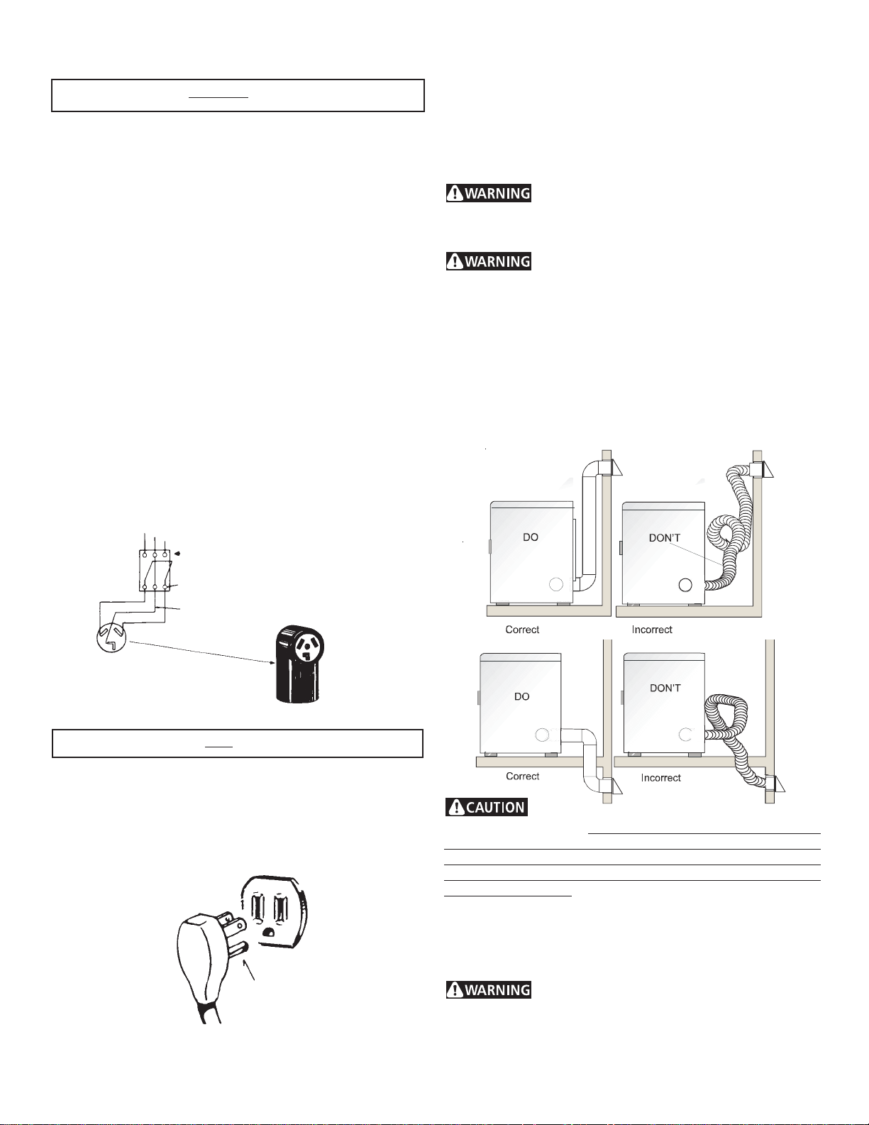
OUTLET RECEPTACLE - NEMA 10-30R or 14-30R receptacle to
be located so the power supply cord is accessible when the dryer
is in the installed position.
EXHAUST SYSTEM REQUIREMENTS
Use only 4 inch (10.2 cm) diameter (minimum) rigid or flexible
metal duct and approved vent hood which has a swing-out
damper(s) that open when the dryer is in operation. When the
dryer stops, the dampers automatically close to prevent drafts
and the entrance of insects and rodents. To avoid restricting the
outlet, maintain a minimum of 12 inches (30.5 cm) clearance
between the vent hood and the ground or any other obstruction.
The following are specific requirements for
proper and safe operation of your dryer. Failure to follow
these instructions can create excessive drying times and
fire hazards.
Do not install a clothes dryer with flexible
plastic venting materials. If your present system is made up
of plastic duct or metal foil duct, replace it with a rigid or flexible
metal duct. In Canada and the United States if metal (foil type)
duct is installed, it must be of a specific type identified by the
appliance manufacturer as suitable for use with clothes dryers
and in the United States must also comply with the Outline for
Clothes Dryer Transition Duct, UL standard 2158A. Flexible
venting materials are known to collapse, be easily crushed and
trap lint. These conditions will obstruct clothes dryer airflow and
increase the risk of fire. Ensure the present duct is free of
any lint prior to installing dryer duct.
Typical 3-wire installation
POWER SUPPLY
OUTLET
RECEPTACLE
(COPPER)
SUBJECT TO LOCAL REGULATIONS
CIRCUIT - Individual 15 amp. branch circuit fused with a 15 amp.
maximum time delay fuse or circuit breaker.
POWER SUPPLY - 3 wire, 120 volt single phase, 60 Hz,
Alternating Current.
POWER SUPPLY CORD - The dryer is equipped with a 120 volt
3-wire power cord.
NOTE: Do not under
any circumstances
remove grounding
prong from plug.
3 WIRE GROUNDED NEUTRAL
120-240 VOLT 60 CYCLE
MAIN FUSE BOX
30 AMP DELAYED ACTION
FUSES
OR CIRCUIT BREAKER
NEUTRAL WIRE
NEMA 10-30R (COPPER)
GAS Dryer
GROUNDING PRONG
- Risk of Fire - A clothes dryer must be
exhausted outdoors. Do not exhaust dryer into a chimney, a
wall, a ceiling, an attic, a crawl space or any concealed space
of a building. A clothes dryer produces combustible lint. If the
dryer is not exhausted outdoors, some fine lint will be expelled
into the laundry area. An accumulation of lint in any area of the
home can create a health and fire hazard. The dryer must be
connected to an exhaust outdoors. Regularly inspect the
outdoor exhaust opening and remove any accumulation of lint
around the outdoor exhaust opening and in the surrounding
area.
Do not allow combustible materials (for
example: clothing, draperies/curtains, paper) to come in
contact with exhaust system. The dryer MUST NOT be
exhausted into a chimney, a wall, a ceiling, or any concealed
space of a building which can accumulate lint, resulting in a fire
hazard.
3
Exceeding the length of duct pipe or number
of elbows allowed in the "MAXIMUM LENGTH" charts can
cause an accumulation of lint in the exhaust system. Plugging
the system could create a fire hazard, as well as increase drying
times.
Do not screen the exhaust ends of the vent
system, nor use any screws, rivets or other fastening means
that extend into the duct and catch lint to assemble the
exhaust system. Lint can become caught in the screen, on the
screws or rivets, clogging the duct work and creating a fire hazard
as well as increasing drying times. Use an approved vent hood
to terminate the duct outdoors, and seal all joints with duct tape.
All male duct pipe fittings MUST be installed downstream with
the flow of air.
Explosion hazard. Do not install the dryer
where gasoline or other flammables are kept or stored. If
the dryer is installed in a garage, it must be a minimum of 18
inches (45.7 cm) above the floor. Failure to do so can result in
death, explosion, fire or burns.
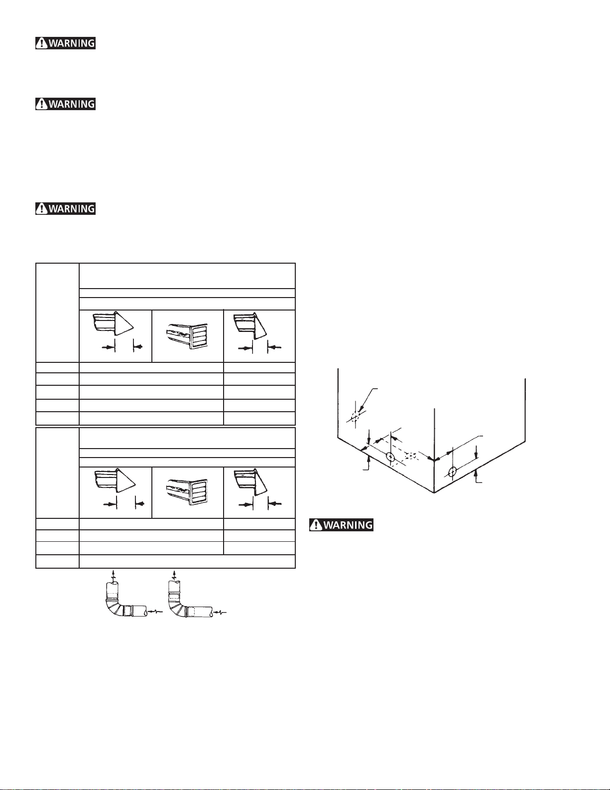
MAXIMUM LENGTH
of 4” (10.2 cm) Dia. Rigid Metal Duct
VENT HOOD TYPE
Number
of
90°
Turns
0 60 ft.(18.28 m) 48 ft.(14.63 m)
1 52 ft.(15.84 m) 40 ft.(12.19 m)
2 44 ft.(13.41 m) 32 ft. (9.75 m)
3 32 ft.(9.75 m) 24 ft. (7.31 m)
4 28 ft.(8.53 m) 16 ft. (4.87 m)
Number
of
90°
Turns
(Preferred)
Louvered
4”
(10.2 cm)
MAXIMUM LENGTH
of 4” (10.2 cm) Dia. Flexible Metal Duct
VENT HOOD TYPE
(Preferred)
Louvered
2½"
(6.35 cm)
than 0.75 inches of water column, the system is acceptable.
If the manometer reading is higher than 0.75 inches of water
column, the system is too restrictive and the installation is
unacceptable.
Although vertical orientation of the exhaust system is acceptable,
certain extenuating circumstances could affect the performance
of the dryer:
• Only the rigid metal duct work should be used.
• Venting vertical through a roof may expose the exhaust system
to down drafts causing an increase in vent restriction.
• Running the exhaust system through an uninsulated area may
cause condensation and faster accumulation of lint.
• Compression or crimping of the exhaust system will cause an
increase in vent restriction.
The exhaust system should be inspected and cleaned a minimum
of every 18 months with normal usage. The more the dryer is
used, the more often you should check the exhaust system and
vent hood for proper operation.
EXHAUST DIRECTION
All dryers shipped from the factory are set up for rear exhausting.
However, on electric dryers, exhausting can be to the right or left
side of the cabinet or the bottom of the dryer. On gas dryers,
exhausting can be to the right side of the cabinet or the bottom of
the dryer. Directional exhausting can be accomplished by installing
Exhaust Kit, P/N 131456800, available through your parts
distributor. Follow the instructions supplied with the kit.
EXHAUST DUCT LOCATING DIMENSIONS
SAME AS OTHER SIDESAME AS OTHER SIDE
SAME AS OTHER SIDE
SAME AS OTHER SIDESAME AS OTHER SIDE
5 7/8"5 7/8"
5 7/8"
5 7/8"5 7/8"
4 3/8"4 3/8"
4 3/8"
4 3/8"4 3/8"
3 3/4"3 3/4"
3 3/4"
3 3/4"3 3/4"
(9.5 cm)(9.5 cm)
(9.5 cm)
(9.5 cm)(9.5 cm)
3 3/4"3 3/4"
3 3/4"
3 3/4"3 3/4"
13 1/2"13 1/2"
13 1/2"
13 1/2"13 1/2"
4”
(10.2 cm)
0 30 ft. (9.14 m) 18 ft. (5.49 m)
1 22 ft. (6.71 m) 14 ft. (4.27 m)
2 14 ft. (4.27 m) 10 ft. (3.05 m)
3 NOT RECOMMENDED
CORRECT INCORRECT
INSTALL MALE FITTINGS IN CORRECT DIRECTION
2½"
(6.35 cm)
In installations where the exhaust system is not described in the
charts, the following method must be used to determine if the
exhaust system is acceptable:
1. Connect an inclined or digital manometer between the
dryer and the point the exhaust connects to the dryer.
2. Set the dryer timer and temperature to air fluff (cool down)
and start the dryer.
3. Read the measurement on the manometer.
4. The system back pressure MUST NOT be higher than 0.75
inches of water column. If the system back pressure is less
GAS SUPPLY REQUIREMENTS
Replace copper connecting pipe that is not
plastic-coated. Stainless steel or plastic-coated brass MUST
be used.
1. Installation MUST conform with local codes, or in the absence
of local codes, with the National Fuel Gas Code, ANSI Z223.1
(latest edition).
2. The gas supply line should be of 1/2 inch (1.27 cm) pipe.
3. If codes allow, flexible metal tubing may be used to connect
your dryer to the gas supply line. The tubing MUST be
constructed of stainless steel or plastic-coated brass.
4. The gas supply line MUST have an individual shutoff valve.
5. A 1/8 inch (0.32 cm) N.P.T. plugged tapping, accessible for
test gauge connection, MUST be installed immediately
upstream of the gas supply connection to the dryer.
6. The dryer MUST be disconnected from the gas supply piping
system during any pressure testing of the gas supply piping
system at test pressures in excess of 1/2 psig (3.45 kPa).
7. The dryer MUST be isolated from the gas supply piping system
during any pressure testing of the gas supply piping system at
test pressures equal to or less than 1/2 psig (3.45 kPa).
4
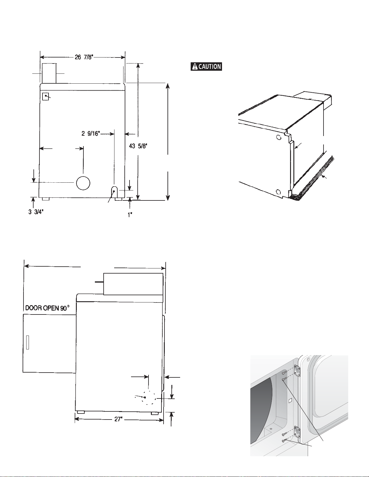
ROUGH-IN DIMENSIONS
UNPACKING
1. Using the four shipping carton corner posts (two on each
side), carefully lay the dryer on its left side and remove foam
shipping base.
(9.5 cm)
(68.3 cm)
43/8"
(11.2cm)
ELECTRIC CONNECTION
REAR VIEWREAR VIEW
REAR VIEW
REAR VIEWREAR VIEW
(6.5 cm)
13 1/2"
3/8" (0.96 cm) DIA. GAS
(110.7 cm)
(2.54 cm)
36"
To prevent damage, do not use the control panel
or coin meter housing as a means to pick up or move the dryer.
2. Return the dryer to an upright position.
FOAM
SHIPPING
PAD
PACKING
REVERSING DOOR SWING
Your dryer is designed so the door swing may be reversed at any
time without additional parts. Conversion is accomplished by
transferring hinges to the opposite side of the cabinet.
To change the direction of the door opening:
47 1/2"
(120.7 cm)
SIDE VIEWSIDE VIEW
SIDE VIEW
SIDE VIEWSIDE VIEW
(11.1 cm)(11.1 cm)
(11.1 cm)
(11.1 cm)(11.1 cm)
OPTIONALOPTIONAL
OPTIONAL
OPTIONALOPTIONAL
VENT VENT
VENT
VENT VENT
(68.6 cm)
4 3/8"4 3/8"
4 3/8"
4 3/8"4 3/8"
KNOCKOUTKNOCKOUT
KNOCKOUT
KNOCKOUTKNOCKOUT
1. Open the dryer door. Remove the four hinge hole plugs from
the left side of the door opening. Place nearby for future
installation.
NOTE: You may need a plastic knife to help pull out the plugs.
Be careful not to scratch the paint.
2. Remove the four screws that secure the door hinges to the
dryer front panel (see below). NOTE: Remove one screw from
each of the two hinges first. Hold the door firmly before
removing the last two screws.
3. Rotate the door 180° and reinstall the door hinges to the dryer
front panel with the four screws.
4. Install the four
hinge hole plugs
in the open
screw holes on
the right side of
the door
opening.
3 3/4"
(9.5 cm)
(Figure 1)
REMOVE 4 SCREWS
(ONE FROM EACH
HINGE FIRST)
5
 Loading...